JP6009251B2 - Millimeter wave transmission module and millimeter wave transmission device - Google Patents
Millimeter wave transmission module and millimeter wave transmission device Download PDFInfo
- Publication number
- JP6009251B2 JP6009251B2 JP2012157368A JP2012157368A JP6009251B2 JP 6009251 B2 JP6009251 B2 JP 6009251B2 JP 2012157368 A JP2012157368 A JP 2012157368A JP 2012157368 A JP2012157368 A JP 2012157368A JP 6009251 B2 JP6009251 B2 JP 6009251B2
- Authority
- JP
- Japan
- Prior art keywords
- signal
- millimeter
- band
- mixer
- reference signal
- Prior art date
- Legal status (The legal status is an assumption and is not a legal conclusion. Google has not performed a legal analysis and makes no representation as to the accuracy of the status listed.)
- Expired - Fee Related
Links
Images


Description
本発明は、ミリ波送信モジュール、ミリ波送信装置およびミリ波受信装置に関する。 The present invention relates to a millimeter wave transmission module, a millimeter wave transmission device, and a millimeter wave reception device.
近年、情報通信の大容量化に伴い、様々なブロ−ドバンドの無線通信システムが提案されてきている。その中で、放送や通信の分野で、特にミリ波の無線通信が利用されている。ミリ波はビ−ムを鋭く絞ることができるので、軌道上に並んだ衛星間や地上での混信を防ぐことができるとともに、特定のエリアに対して反射や混信の影響が小さく、見通し区間では確実に電波を送ることができる。なお、ここで示すミリ波帯とは、マイクロ波帯も含む周波数帯域である。 In recent years, various broadband wireless communication systems have been proposed with an increase in information communication capacity. Among them, millimeter-wave wireless communication is used particularly in the field of broadcasting and communication. Millimeter waves can sharpen the beam sharply, preventing interference between satellites arranged in orbit and on the ground, and are less affected by reflections and interference on specific areas. Radio waves can be sent reliably. In addition, the millimeter wave band shown here is a frequency band including a microwave band.
従来のミリ波帯の無線通信システムとして、例えば、特許文献1(特開2003−258655号公報)では、無線送信機および無線受信機を備えたものが開示されている。 As a conventional millimeter wave band wireless communication system, for example, Japanese Patent Application Laid-Open No. 2003-258655 discloses a wireless communication system including a wireless transmitter and a wireless receiver.
図19は、特許文献1に記載されたミリ波帯の無線送信機1000および無線受信機1500の構成を示す図である。
FIG. 19 is a diagram illustrating configurations of the millimeter wave band
送信機1000は、入力部1100、第1のアップコンバ−ト部1200、第2のアップコンバ−ト部1300、および送信アンテナ1400により構成されている。
The
第1のアップコンバ−ト部1200は、入力される変調波信号を中間周波数に周波数変換する部分であり、周波数ミキサ1201、フィルタ1202、電力合成器1203、増幅器1204、電力分配器1205、基準信号源1206、および減衰器1207を備えている。
The first up-
第1のアップコンバ−ト部1200には、第1のIF信号IF1が入力される。この信号IF1は、例えば、直交マルチキャリア変調方式(OFDM変調方式)等で変調された変調波信号である。
The first IF signal IF1 is input to the first up-convert
周波数ミキサ1201は、入力された第1のIF信号IF1と、基準信号源1206から出力される第1のLO信号(FLO1)とを乗積する。
The
次いで、周波数ミキサ1201の直後に設けられたフィルタ1202は、第1のアップコンバ−ト部1200から出力される信号の成分のみを主に取り出す。ここで、フィルタ1202は、周波数ミキサ1201の出力信号のうち上側波帯の信号(FRF1)を通過選択させる。
Next, the
一方、電力分配器1205が、基準信号源1206が出力した信号(FLO1)の一部を分配している。減衰器1207は、分配された信号のレベルを調整する。減衰器1207から出力された信号(FLO1)は、電力合成器1203で、信号(FRF1)と合成される。
On the other hand, the
これにより、送信機へ入力された変調波信号から中間周波数信号に変換された信号(FRF1)と基準信号となる信号(FLO1)との中間周波数多重信号が生成される。この中間周波数多重信号が、アンプ1204により増幅され、増幅された中間周波数多重信号が、第2のIF信号IF2(FLO1+FRF1)として、第2のアップコンバ−ト部1300へ入力される。
As a result, an intermediate frequency multiplexed signal of the signal (FRF1) converted from the modulated wave signal input to the transmitter to the intermediate frequency signal and the signal (FLO1) serving as the reference signal is generated. The intermediate frequency multiplex signal is amplified by the
第2のアップコンバ−ト部1300は、入力される信号IF2をミリ波帯に周波数変換する部分であり、ミキサ1301、フィルタ1302、アンプ1303、および局部発振器1304を備えている。
The
第2のアップコンバ−ト部1300に、第1のアップコンバ−ト部1200から出力された信号IF2が入力されると、ミキサ1301は、信号(FRF1)と信号(FLO1)とを含む中間周波数多重波信号(すなわちIF2)と、局部発振器1304から出力される第2のLO信号(FLO2)とを乗積し、ミリ波帯へのアップコンバ−トを行なう。
When the signal IF2 output from the
次いで、ミキサ1301の直後に設けられたフィルタ1302が、アップコンバ−トされた無線多重信号に対して、所望の周波数のみの無線多重信号を通過させる。これにより、無線変調信号成分(FRF1+FLO2)と、無線基準信号成分(FLO1+FLO2)とを含む無線多重波信号が生成される。この無線多重波信号が、アンプ1303により増幅され、増幅された無線多重波信号が送信アンテナ1400に出力される。
Next, a
そして、送信アンテナ1400すなわち送信機1000から、無線基準信号成分(FLO1+FLO2)および無線変調信号成分(FRF1+FLO2)から成る無線多重波信号2000が送信される。
Then, a radio multi-wave signal 2000 composed of a radio reference signal component (FLO1 + FLO2) and a radio modulation signal component (FRF1 + FLO2) is transmitted from the
次に、送信機1000から送信された信号を受信する受信機1500について説明する。
Next, the
受信機1500は、受信アンテナ1600、第1のダウンコンバ−ト部1700、および第2のダウンコンバ−ト部1800により構成されている。受信機1500は、送信機1000から送信された信号を受信し、受信した信号を元の変調波信号(IF1)にダウンコンバ−トする。
The
受信アンテナ1600において、送信機1000の送信アンテナ1400から送られてきた、基準信号成分(FLO1+FLO2)および無線変調信号成分(FRF1+FLO2)から成る無線多重波信号2000が受信される。
The
第1のダウンコンバ−ト部1700は、入力される無線多重波信号を中間周波数信号に周波数変換する部分であり、フィルタ1701、アンプ1702、ミキサ1703、アンプ1704、および局部発振器1705を備えている。
The first down-
フィルタ1701が必要な信号を通過させる。そして、通過した信号をアンプ1702が増幅する。次いで、ミキサ1703は、局部発振器1705からの信号(FLO2)で、第1の周波数変換を行う。すなわち、基準信号成分(FLO1+FLO2)と無線変調信号成分(FRF1+FLO2)とは、中間周波数多重波信号である第2のIF信号IF2(すなわちFLO1、FRF1)にダウンコンバ−トされる。
A
これにより、第2のIF信号IF2(FLO1、FRF1)が生成される。この第2のIF信号が、アンプ1704により増幅され、増幅された信号IF2が第2のダウンコンバ−ト部1800に出力される。
Thus, the second IF signal IF2 (FLO1, FRF1) is generated. The second IF signal is amplified by the
第2のダウンコンバ−ト部1800は、入力される第2のIF信号IF2を第1のIF信号IF1に周波数変換する部分であり、分配器1801、フィルタ1802、フィルタ1803、ミキサ1804、アンプ1805、および出力部1806を備えている。
The second down-
第2のダウンコンバ−ト部1800に、第2のIF信号IF2が入力されると、該信号は分配器1801で分配される。分配された一方の信号は、信号(FRF1)のみが通過できるフィルタ1802を介し、ミキサ1804に入力される。また、他方の信号は、信号(FLO1)のみが通過できるフィルタ1803を介し、アンプ1805によって増幅された後、ミキサ1804に入力される。
When the second IF signal IF2 is input to the
ミキサ1804は、信号(FRF1)と信号(FLO1)とを乗積する。これにより、信号(FRF1)がダウンコンバ−トされる。すなわち、第1のIF信号IF1に復調さ
れる。
The
以上により、受信機1500では、第1のIF信号IF1が復調される。この第1のIF信号IF1は、送信機1000に入力された第1のIF信号IF1と同じである。
As described above, the
しかしながら、特許文献1に記載の送信機1000は、以下のような問題点を有している。
However, the
第1のアップコンバ−ト部1200から出力された信号IF2がミキサ1301に入力されると、ミキサ1301は、信号(FRF1)と信号(FLO1)とを含む中間周波数多重波信号を、局部発振器1304から出力される第2のLO信号(FLO2)を用いて、無線周波数帯へアップコンバ−トする。
When the signal IF2 output from the first up-
信号FLO1は、正弦波の連続波(CW波)で、信号FRF1に比べて、パワ−レベルが同等以上に大きい信号であることが必要である。つまり、信号FLO1は、変調信号波FRF1に比べて、帯域幅が狭く特定の周波数であるため、ピ−クパワ−が、極度に大きい信号となる。 The signal FLO1 is a continuous sinusoidal wave (CW wave) and needs to be a signal having a power level equal to or higher than that of the signal FRF1. That is, since the signal FLO1 has a narrower bandwidth and a specific frequency than the modulated signal wave FRF1, the peak power becomes an extremely large signal.
この結果、周波数ミキサ1301の出力は、信号FLO1によって飽和し歪んでしまい、本来伝送すべき信号成分である信号FRF1を適切にアップコンバートことができず、十分な伝送距離を確保できないという問題点があった。
As a result, the output of the
それゆえに、本発明の目的は、伝送すべき信号の成分を適切にアップコンバートすることができるミリ波送信モジュール、ミリ波送信装置、およびそのようなミリ波送信装置から送信された信号を受信するミリ波受信装置を提供することである。 Therefore, an object of the present invention is to receive a signal transmitted from a millimeter-wave transmission module, a millimeter-wave transmission device, and such a millimeter-wave transmission device that can appropriately upconvert components of a signal to be transmitted. It is to provide a millimeter wave receiver.
上記課題を解決するために、本発明のミリ波送信モジュールは、基準信号を逓倍した逓倍基準信号を生成する逓倍器と、逓倍基準信号に基づいて、基準信号によって周波数変換された中間周波数信号をミリ波帯へアップコンバートするミリ波帯第1ミキサと、逓倍基準信号に基づいて、基準信号をミリ波帯へアップコンバートするミリ波帯第2ミキサと、ミリ波帯第1ミキサおよびミリ波帯第2ミキサでアップコンバ−トされた信号を合成してミリ波多重信号を生成するミリ波帯合成部とを備える。 In order to solve the above problems, a millimeter wave transmission module of the present invention includes a multiplier that generates a multiplied reference signal obtained by multiplying a reference signal, and an intermediate frequency signal that is frequency-converted by the reference signal based on the multiplied reference signal. A millimeter-wave band first mixer that up-converts to the millimeter-wave band, a millimeter-wave band second mixer that up-converts the reference signal to the millimeter-wave band based on the multiplied reference signal, a millimeter-wave band first mixer, and a millimeter-wave band And a millimeter-wave band synthesizer that synthesizes the signals up-converted by the second mixer to generate a millimeter-wave multiplexed signal.
好ましくは、ミリ波多重信号の下側波帯をイメージ信号として除去するミリ波バンドパスフィルタを備える。 Preferably, a millimeter wave band pass filter for removing the lower sideband of the millimeter wave multiplexed signal as an image signal is provided.
好ましくは、ミリ波帯第1ミキサおよびミリ波帯第2ミキサは、2次の偶高調波ミキサである。 Preferably, the millimeter wave band first mixer and the millimeter wave band second mixer are second-order even harmonic mixers.
本発明のミリ波送信装置は、基準信号を出力する基準信号源と、基準信号に基づいて、ベースバンド信号を中間周波数信号にアップコンバートするIF帯ミキサと、基準信号源から出力された基準信号を逓倍した逓倍基準信号を生成する逓倍器と、逓倍基準信号に基づいて、中間周波数信号をミリ波帯へアップコンバートするミリ波帯第1ミキサと、逓倍基準信号に基づいて、基準信号源から出力された基準信号をミリ波帯へアップコンバートするミリ波帯第2ミキサと、ミリ波帯第1ミキサおよびミリ波帯第2ミキサでアップコンバ−トされた信号を合成してミリ波多重信号を生成するミリ波帯合成部とを備える。 The millimeter wave transmitter of the present invention includes a reference signal source that outputs a reference signal, an IF band mixer that upconverts a baseband signal to an intermediate frequency signal based on the reference signal, and a reference signal that is output from the reference signal source From a reference signal source based on the multiplied reference signal, a multiplier that generates a multiplied reference signal multiplied by the frequency, a first mixer in the millimeter wave band that upconverts the intermediate frequency signal to the millimeter wave band based on the multiplied reference signal, Millimeter-wave multiplexed signal by combining the up-converted signal in the millimeter-wave band first mixer and the millimeter-wave band first mixer and the millimeter-wave band second mixer to up-convert the output reference signal to the millimeter-wave band And a millimeter-wave band synthesizer for generating
好ましくは、ミリ波多重信号の下側波帯をイメージ信号として除去するミリ波バンドパスフィルタを備える。 Preferably, a millimeter wave band pass filter for removing the lower sideband of the millimeter wave multiplexed signal as an image signal is provided.
好ましくは、ミリ波帯第1ミキサおよびミリ波帯第2ミキサは、2次の偶高調波ミキサである。 Preferably, the millimeter wave band first mixer and the millimeter wave band second mixer are second-order even harmonic mixers.
好ましくは、基準信号源から出力された基準信号を増幅し、3分配してIF帯ミキサと、逓倍器と、ミリ波帯第2ミキサへ供給する増幅分配部を備える。 Preferably, an amplification distribution unit is provided that amplifies the reference signal output from the reference signal source, and distributes the reference signal to an IF band mixer, a multiplier, and a millimeter wave band second mixer.
好ましくは、IF帯ミキサから出力される中間周波数信号の下側波帯を通すIF帯バンドパスフィルタを備える。 Preferably, an IF band pass filter that passes the lower sideband of the intermediate frequency signal output from the IF band mixer is provided.
本発明のミリ波送信装置は、基準信号を出力する基準信号源と、基準信号に基づいて、第1のベースバンド信号を第1の中間周波数信号にアップコンバートするIF帯第1ミキサと、基準信号に基づいて、第2のベースバンド信号を第2の中間周波数信号にアップコンバートするIF帯第2ミキサと、第1の中間周波数信号および第2の中間周波数信号を合成するIF帯合成部と、基準信号源から出力された基準信号を逓倍した逓倍基準信号を生成する逓倍器と、逓倍基準信号に基づいて、合成された中間周波数信号をミリ波帯へアップコンバートするミリ波帯第1ミキサと、逓倍基準信号に基づいて、基準信号源から出力された基準信号をミリ波帯へアップコンバートするミリ波帯第2ミキサと、ミリ波帯第1ミキサおよびミリ波帯第2ミキサでアップコンバ−トされた信号を合成してミリ波多重信号を生成するミリ波帯合成部とを備える。 A millimeter-wave transmitter of the present invention includes a reference signal source that outputs a reference signal, an IF band first mixer that up-converts a first baseband signal into a first intermediate frequency signal based on the reference signal, a reference An IF band second mixer that up-converts the second baseband signal into a second intermediate frequency signal based on the signal; and an IF band combiner that combines the first intermediate frequency signal and the second intermediate frequency signal. A multiplier that generates a multiplied reference signal obtained by multiplying the reference signal output from the reference signal source, and a first millimeter-wave band mixer that upconverts the synthesized intermediate frequency signal to the millimeter-wave band based on the multiplied reference signal And a millimeter-wave band second mixer for up-converting the reference signal output from the reference signal source to the millimeter-wave band based on the multiplied reference signal, the millimeter-wave band first mixer, and the millimeter-wave band second mixer Up service converter - by combining the bets signal and a millimeter wave band synthesizing unit for generating a millimeter wave multiplex signal.
好ましくは、ミリ波多重信号の下側波帯をイメージ信号として除去するミリ波バンドパスフィルタを備える。 Preferably, a millimeter wave band pass filter for removing the lower sideband of the millimeter wave multiplexed signal as an image signal is provided.
好ましくは、ミリ波帯第1ミキサおよびミリ波帯第2ミキサは、2次の偶高調波ミキサである。 Preferably, the millimeter wave band first mixer and the millimeter wave band second mixer are second-order even harmonic mixers.
好ましくは、基準信号源から出力された基準信号を増幅し、4分配して、IF帯第1ミキサと、逓倍器と、ミリ波帯第2ミキサと、IF帯第2ミキサへ供給するための複数のアンプを備える。 Preferably, the reference signal output from the reference signal source is amplified, divided into four parts, and supplied to the IF band first mixer, the multiplier, the millimeter wave band second mixer, and the IF band second mixer. With multiple amplifiers.
好ましくは、IF帯第1ミキサから出力される第1の中間周波数信号の下側波帯を通すIF帯第1バンドパスフィルタと、IF帯第2ミキサから出力される第2の中間周波数信号の下側波帯を通すIF帯第2バンドパスフィルタとを備える。 Preferably, the IF band first bandpass filter that passes the lower sideband of the first intermediate frequency signal output from the IF band first mixer, and the second intermediate frequency signal output from the IF band second mixer An IF band second bandpass filter that passes the lower sideband.
本発明のミリ波受信装置は、ミリ波多重信号をダウンコンバートして中間周波数多重信号を生成するミリ波帯ミキサと、中間周波数多重信号から第1の中間周波数信号を出力する第1のフィルタと、中間周波数多重信号から第2の中間周波数信号を出力する第2のフィルタと、中間周波数多重信号から基準信号を出力する第3のフィルタと、基準信号に基づいて、第1の中間周波数信号をダウンコンバートして、第1のベースバンド信号を生成するIF帯第1ミキサと、基準信号に基づいて、第2の中間周波数信号をダウンコンバートして、第2のベースバンド信号を生成するIF帯第2ミキサとを備える。 A millimeter-wave receiver of the present invention includes a millimeter-wave band mixer that down-converts a millimeter-wave multiplexed signal to generate an intermediate-frequency multiplexed signal, a first filter that outputs a first intermediate-frequency signal from the intermediate-frequency multiplexed signal, A second filter that outputs a second intermediate frequency signal from the intermediate frequency multiplex signal, a third filter that outputs a reference signal from the intermediate frequency multiplex signal, and a first intermediate frequency signal based on the reference signal An IF band first mixer that downconverts to generate a first baseband signal, and an IF band that downconverts the second intermediate frequency signal to generate a second baseband signal based on the reference signal A second mixer.
本発明によれば、伝送すべき信号の成分を適切にアップコンバートすることができる。 According to the present invention, components of a signal to be transmitted can be appropriately up-converted.
以下、本発明の実施形態について、図面を用いて説明する。
(第1の実施形態)
図1は、第1の実施形態のミリ波送信装置の構成を示す図である。
Hereinafter, embodiments of the present invention will be described with reference to the drawings.
(First embodiment)
FIG. 1 is a diagram illustrating a configuration of the millimeter wave transmission device according to the first embodiment.
図1を参照して ミリ波送信装置1は、入力端子5と、ベースバンド回路2と、IF回路3と、ミリ波ICモジュール4とを備える。
With reference to FIG. 1, the
入力端子5から、第1の変調信号bb1が入力される。
図2は、第1の変調信号bb1の周波数スペクトルを表わす図である。
A first modulation signal bb1 is input from the input terminal 5.
FIG. 2 is a diagram representing the frequency spectrum of first modulated signal bb1.
図2に示すように、第1の変調信号bb1の周波数fbb1は、400MHz〜800MHz、1000MHz〜2100MHzである。第1の変調信号bb1は、放送波信号であって、UHF帯の地上デジタル放送信号とBS/CS110度放送のIF信号が合成された信号に相当する。第1の変調信号bb1を、以下ではベ−スバンド信号と呼ぶこともある。 As shown in FIG. 2, the frequency fbb1 of the first modulated signal bb1 is 400 MHz to 800 MHz and 1000 MHz to 2100 MHz. The first modulation signal bb1 is a broadcast wave signal, and corresponds to a signal obtained by combining a UHF band terrestrial digital broadcast signal and a BS / CS 110 degree broadcast IF signal. Hereinafter, the first modulation signal bb1 may be referred to as a baseband signal.
尚、IF帯域の周波数バンドパスフィルタとして、広帯域で急峻性能が高いものを、以下記述するミリ波送信装置とミリ波受信装置で用いれば、第1の変調信号bb1は、たとえば200MHz〜2500MHzの帯域の信号であっても構わない。 If the IF band frequency bandpass filter having a wide bandwidth and high steep performance is used in a millimeter wave transmission device and a millimeter wave reception device described below, the first modulation signal bb1 is, for example, a band of 200 MHz to 2500 MHz. This signal may be used.
ベースバンド信号bb1は、望ましくはデジタル変調信号の電力レベルの変動の少ない広帯域信号が望ましい。ベ−スバンド信号bb1は、75/50Ω変換部191でインピーダンス変換され、ベ−スバンド回路2内のアンプ6で増幅され、さらにリミタ7でレベル制限され、IF回路3内のIF帯ミキサ8に入力される。
The baseband signal bb1 is preferably a wideband signal with little fluctuation in the power level of the digital modulation signal. The baseband signal bb1 is impedance-converted by a 75 /
図1において、基準信号源15から出力される周波数fstdが5.5737GHzである基準信号stdが増幅分配部14で適度なレベルまで増幅された後、3分配される。一つ目は、IF帯ミキサ8に局部発振信号として送られる。2つ目は、減衰器(T1)17でレベル調整された後、ミリ波ICモジュ−ル4の端子13Bからミリ波ICモジュ−ル4中のミリ波帯ミキサ32bに入力される。3つ目は、整合器16を介して、ミリ波ICモジュ−ル4中のM逓倍型マルチプライア(Mは2以上の自然数、本実施の形態ではM=5とする)36へ送られる。
In FIG. 1, the reference signal std output from the
図3は、基準信号stdの周波数スペクトルを示す図である。
基準信号stdは、周波数fstdが5.573GHzのCW(連続波)信号である。
FIG. 3 is a diagram illustrating a frequency spectrum of the reference signal std.
The reference signal std is a CW (continuous wave) signal having a frequency fstd of 5.573 GHz.
IF帯ミキサ8は、ベ−スバンド信号bb1を、基準信号std(局部発振信号)によってIF帯にアップコンバートする。IF帯バンドパスフィルタ(BPF)9は、アップコンバートされた信号のうち、下側波帯のみを通過させて、第1のIF信号IF1を出力する。第1のIF信号IF1は、IFアンプ10で増幅され、さらに減衰器(T2)11とIFアンプ12によって適宜レベル調整された後、ミリ波ICモジュ−ル4の入力端子13Aから、ミリ波ICモジュ−ル4中のミリ波帯ミキサ32aに送られる。
The IF band mixer 8 up-converts the baseband signal bb1 to the IF band by the reference signal std (local oscillation signal). The IF bandpass filter (BPF) 9 passes only the lower sideband out of the upconverted signal and outputs the first IF signal IF1. The first IF signal IF1 is amplified by the
図4は、第1のIF信号IF1の周波数スペクトルを表わす図である。
本実施の形態では、第1のIF信号IF1の周波数fIF1は、下側波帯の信号波3.473GHz〜4.573GHz、4.773GHz〜5.173GHzである。つまり、IF帯バンドパスフィルタ9aが、下側帯の信号を選択していることから、第1のIF信号IF1の周波数fIF1は、下記の関係で表現される。
FIG. 4 is a diagram illustrating the frequency spectrum of the first IF signal IF1.
In the present embodiment, the frequency fIF1 of the first IF signal IF1 is a lower sideband signal wave of 3.473 GHz to 4.573 GHz, 4.773 GHz to 5.173 GHz. That is, since the IF band-pass filter 9a selects the lower band signal, the frequency fIF1 of the first IF signal IF1 is expressed by the following relationship.
fstd−fbb1=fIF1・・・(1)
M逓倍型マルチプライア(Mは2以上の自然数、本実施の形態ではM=5とする)36は、基準信号stdを5逓倍して、逓倍基準信号std_5を出力する。5逓倍された逓倍基準信号std_5は、2分配されてそれぞれアンプ37a,37bで増幅されて、局部発振信号としてミリ波帯ミキサ32aおよびミリ波帯ミキサ32bへ送られる。
fstd−fbb1 = fIF1 (1)
An M-multiplier (M is a natural number greater than or equal to 2 and M = 5 in the present embodiment) 36 multiplies the reference signal std by 5 and outputs a multiplied reference signal std_5. The multiplied reference signal std_5 multiplied by 5 is divided into two, amplified by the
ミリ波帯ミキサ32aは、2次の偶高調波ミキサであり、入力された5逓倍された逓倍基準信号std_5をさらに2逓倍して逓倍基準信号std_10を生成する。したがって、元の基準信号stdはト−タルで10逓倍される。逓倍基準信号std_10の周波数RFLOは、55.73GHz(10×5.573GHz)である。ミリ波帯ミキサ32aは、入力端子13Aから入力された第1のIF信号IF1を基準信号std_10によってミリ波帯にアップコンバートして、第1のミリ波変調信号RF1を出力する。第1のミリ波変調信号RF1の周波数をfRF1とする。
The millimeter wave band mixer 32a is a second-order even harmonic mixer, and further multiplies the input multiplied reference signal std_5 multiplied by 5 to generate a multiplied reference signal std_10. Therefore, the original reference signal std is multiplied by 10 by the total. The frequency RFLO of the multiplied reference signal std_10 is 55.73 GHz (10 × 5.573 GHz). The millimeter wave band mixer 32a up-converts the first IF signal IF1 input from the
ミリ波帯ミキサ32bは、2次の偶高調波ミキサであり、入力された5逓倍された逓倍基準信号std_5をさらに2逓倍して逓倍基準信号std_10を生成する。したがって、元の基準信号stdはト−タルで10逓倍される。逓倍基準信号std_10の周波数RFLOは、55.73GHz(=10×5.573GHz)である。ミリ波帯ミキサ32bは、入力端子13Bから入力された基準信号stdを逓倍基準信号std_10によってミリ波帯にアップコンバートして、ミリ波基準信号RFstdを出力する。ミリ波基準信号RFstdの周波数をfRFstdとする。
The millimeter wave band mixer 32b is a second-order even harmonic mixer, and further multiplies the input multiplied reference signal std_5 multiplied by 5 to generate a multiplied reference signal std_10. Therefore, the original reference signal std is multiplied by 10 by the total. The frequency RFLO of the multiplied reference signal std_10 is 55.73 GHz (= 10 × 5.573 GHz). The millimeter wave band mixer 32b up-converts the reference signal std input from the
ミリ波帯電力合成器29は、ミリ波帯ミキサ32aでアップコンバ−トされた信号とミリ波帯ミキサ32bでアップコンバートされた信号を合成して、ミリ波帯多重信号を出力する。
The millimeter wave
ミリ波帯バンドパスフィルタ33は、ミリ波多重信号の上側波帯を通過させ、下側波帯をイメ−ジ信号として除去する。上側波帯信号は、アンプ34で増幅された後、ミリ波ICモジュ−ル4と一体化されたアンテナ35によって、ミリ波送信信号として放射される。
The millimeter wave band-
図5は、ミリ波送信信号の周波数スペクトルを示す図である。
ミリ波送信信号は、ミリ波基準信号RFstdと、第1のミリ波変調信号RF1で構成され、下記のような関係になる。
FIG. 5 is a diagram illustrating a frequency spectrum of a millimeter wave transmission signal.
The millimeter wave transmission signal includes a millimeter wave reference signal RFstd and a first millimeter wave modulation signal RF1, and has the following relationship.
<第1のミリ波変調信号RF1について>
fIF1+10×fstd=fRF1・・・(2)
式(2)は、式(1)によって以下のように変形される。
<Regarding First Millimeter-Wave Modulation Signal RF1>
fIF1 + 10 × fstd = fRF1 (2)
Equation (2) is transformed as follows by Equation (1).
11×fdtd−fbb1=fRF1・・・(3)
<ミリ波基準信号RFstdについて>
fstd+10×fstd=11×fstd=fRFstd ・・・(4)
上記のようにミリ波送信装置1内のミリ波基準信号RFstd、および第1のミリ波変調信号RF1の周波数関係は、基準信号stdの周波数によってのみ決定される。そのため、ミリ波送信装置1の周波数調整は、基準信号stdの周波数fstdを調整すればよく、著しく容易になる。
11 × fdtd−fbb1 = fRF1 (3)
<About the millimeter wave reference signal RFstd>
fstd + 10 × fstd = 11 × fstd = fRFstd (4)
As described above, the frequency relationship between the millimeter wave reference signal RFstd and the first millimeter wave modulation signal RF1 in the
以上のような構成では、ミリ波ICモジュ−ル4中のミリ波帯ミキサ32aには第1のIF信号IF1が、ミリ波帯ミキサ32bには基準信号stdがそれぞれ独立に入力される。ミリ波帯ミキサ32aには、飽和領域まで第1のIF信号1F1を入力することができるため、第1のIF信号の歪が生じないとうメリットがある。 In the above configuration, the first IF signal IF1 is input to the millimeter wave band mixer 32a in the millimeter wave IC module 4 and the reference signal std is input to the millimeter wave band mixer 32b independently. Since the first IF signal 1F1 can be input to the millimeter wave band mixer 32a up to the saturation region, there is an advantage that distortion of the first IF signal does not occur.
従来では、基準信号のピ−ク信号が、第1のIF信号より極度に大きく、入力されるミリ波帯ミキサは、歪易く、変調信号も十分レベルまで入力することができなかった。とりわけ、入力変調信号が、デジタル変調信号の場合、広帯域で時間的な電力レベル変動が小さく、一方CW信号の基準信号は周波数1点の狭帯域の信号でレベルが大きくかつピ−クレベルも大きい。このように、基準信号と入力変調信号とは対照的であり、従来のように、同じ1つのミキサで基準信号と入力変調信号を一緒にアップコンバ−トしようとすると、基準信号のピ−ク時の信号は、IF信号より、略10dB以上大きく、入力されるミリ波帯ミキサは、歪易く、本来伝送すべき変調信号は十分レベルまでアップコンバ−トすることができなく、無線周波数帯のミリ波帯で十分な出力を確保することできなかった。 Conventionally, the peak signal of the reference signal is extremely larger than the first IF signal, and the input millimeter wave band mixer is easily distorted, and the modulation signal cannot be input to a sufficient level. In particular, when the input modulation signal is a digital modulation signal, the temporal power level fluctuation is small in a wide band, while the reference signal of the CW signal is a narrow band signal at one frequency and has a large level and a high peak level. In this way, the reference signal and the input modulation signal are in contrast, and when the reference signal and the input modulation signal are to be up-converted together by the same single mixer as in the prior art, the peak of the reference signal is obtained. The time signal is about 10 dB or more larger than the IF signal, and the input millimeter wave band mixer is easily distorted, and the modulation signal to be originally transmitted cannot be up-converted to a sufficient level. Sufficient output could not be secured in the millimeter wave band.
本実施の形態では、ミリ波帯ミキサ32aおよびミリ波帯ミキサ32bで独立して周波数アップコンバ−ジョンすることによって、歪が生じにくく、本来伝送すべきミリ波変調信号RF1を、十分な送信出力まで増強できる。その結果、伝送距離が2倍以上拡大し、歪が小さくなり、良好な受信CN特性(キャリア対ノイズ特性)を得ることができる。 In the present embodiment, the millimeter-wave band mixer 32a and the millimeter-wave band mixer 32b independently perform frequency up-conversion, so that distortion is unlikely to occur and the millimeter-wave modulation signal RF1 to be originally transmitted is sufficiently transmitted. Can be strengthened. As a result, the transmission distance is increased by more than twice, distortion is reduced, and good reception CN characteristics (carrier-to-noise characteristics) can be obtained.
なお、本実施の形態では、ミリ波帯ミキサ32aおよびミリ波帯ミキサ32bの夫々の出力をミリ波帯電力合成器29で合成したが、ミリ波帯ミキサ32a、ミリ波帯ミキサ32bの直後に、夫々アンプを設けることや、さらに周波数フィルタ等を設けた後に、ミリ波帯電力合成器29で合成する構成であっても構わない。ICのチップサイズとの兼ね合いで、ミリ波帯ミキサ32aおよびミリ波帯ミキサ32bの後の構成は、種々の組み合わせが可能である。
In this embodiment, the outputs of the millimeter wave band mixer 32a and the millimeter wave band mixer 32b are combined by the millimeter wave
(第2の実施形態)
以下では、主に第1の実施形態と相違するところのみについて説明する。第1の実施形態では、入力信号として第1の変調信号bb1のみを用いたが、第2の実施形態では、入力信号として、第2の変調信号bb2が追加されるため、第1の実施形態に第2の変調信号系が追加され、第1の実施形態の構成はそのまま、第2の実施形態に引き継がれる。
(Second Embodiment)
In the following, only the differences from the first embodiment will be mainly described. In the first embodiment, only the first modulation signal bb1 is used as the input signal. However, in the second embodiment, since the second modulation signal bb2 is added as the input signal, the first embodiment is used. The second modulation signal system is added to the second embodiment, and the configuration of the first embodiment is used as it is in the second embodiment.
図6は、第2の実施形態のミリ波送信装置の構成を示す図である。
本実施の形態のミリ波送信装置193は、第1の入力端子5aと、第2の入力端子5bと、基準信号源15と、第1のベースバンド回路2aと、第2のベースバンド回路2bと、第1のIF回路38aと、第2のIF回路38bと、ミリ波ICモジュール4とを備える。
FIG. 6 is a diagram illustrating a configuration of the millimeter wave transmission device according to the second embodiment.
The millimeter
本実施の形態では、ミリ波送信装置192には、第1の変調信号bb1のみならず、第2の入力端子5Bから、ベースバンド信号である第2の変調信号bb2が入力される。第2の変調信号bb2は、第2のベ−スバンド回路2bの75/50Ω変換部193でインピーダンス変換され、アンプ96で増幅され、さらにリミタ97でレベル制限され、第2のIF回路38bのIF帯ミキサ8bに送られる。
In the present embodiment, not only the first modulated signal bb1 but also the second modulated signal bb2, which is a baseband signal, is input to the
第1の変調信号bb1が入力される第1のベースバンド回路2aの構成は、図1のベースバンド回路2の構成と同様である。
The configuration of the
図7は、第2の変調信号bb2の周波数スペクトルを示す図である。
図7に示すように、第2の変調信号の周波数bb2は、900MHZ〜2000MHzである。
FIG. 7 is a diagram illustrating a frequency spectrum of the second modulation signal bb2.
As shown in FIG. 7, the frequency bb2 of the second modulation signal is 900 MHZ to 2000 MHz.
第2の変調信号bb2の周波数fbb2は、第1の変調信号bb1の周波数fbb1の周波数帯と重複しても構わない。また、第2の変調信号bb2の周波数fbb2を900MHz〜2000MHzとしたが、IF帯域の周波数バンドパスフィルタとして広帯域で急峻性能が高いものを、ミリ波送信装置とミリ波受信装置で用いれば、たとえば200MHz〜2500MHzであっても構わない。第1の変調信号bb1および第2の変調信号bb2は、望ましくはデジタル変調信号の電力レベルの変動の少ない広帯域信号が望ましい。 The frequency fbb2 of the second modulation signal bb2 may overlap with the frequency band of the frequency fbb1 of the first modulation signal bb1. Further, although the frequency fbb2 of the second modulation signal bb2 is set to 900 MHz to 2000 MHz, if a wide band and high steep performance is used as a frequency band pass filter of the IF band, It may be 200 MHz to 2500 MHz. The first modulation signal bb1 and the second modulation signal bb2 are desirably wideband signals with little fluctuation in the power level of the digital modulation signal.
基準信号源15が出力する基準信号stdの周波数fstdは、5.573GHzである。基準信号stdは、第1のIF回路38aの増幅分配部14aと、第2のIF回路38b内のアンプ14bに送られる。
The frequency fstd of the reference signal std output from the
増幅分配部14aは、図1の増幅分配部14と同様であり、基準信号stdを適度なレベルまで増幅して、3分配する。一つ目は、IF帯ミキサ8aに局部発振信号として送られる。2つ目は、減衰器(T1)17でレベル調整された後、ミリ波ICモジュ−ル4の端子13Bからミリ波ICモジュ−ル4中のミリ波帯ミキサ32bに入力される。3つ目は、整合器16を介して、ミリ波ICモジュ−ル4中のM逓倍型マルチプライア(Mは2以上の自然数、本実施の形態ではM=5とする)36へ送られる。
The amplification /
アンプ14bは、基準信号stdを適度なレベルまで増幅して、IF帯ミキサ8bに局部発振信号として送る。 The amplifier 14b amplifies the reference signal std to an appropriate level and sends it to the IF band mixer 8b as a local oscillation signal.
IF帯ミキサ8bは、入力された第2の変調信号bb2を、入力された基準信号std(局部発振信号)によって、第2のIF帯にアップコンバートする。 The IF band mixer 8b up-converts the input second modulation signal bb2 to the second IF band by the input reference signal std (local oscillation signal).
IF帯バンドパスフィルタ(BPF)9bは、アップコンバートされた信号のうち、上側波帯のみを通過させて、第2のIF信号IF2を出力する。第2のIF信号IF2は、IFアンプ10bで増幅され、減衰器(T3)11bとIFアンプ12bで、適宜レベル調整された後、IF帯電力合成器39へ送られる。
The IF band-pass filter (BPF) 9b passes only the upper side band of the upconverted signal and outputs the second IF signal IF2. The second IF signal IF2 is amplified by the
IF帯電力合成器39は、第1のIF信号IF1と第2のIF信号IF2とを合成して、IF多帯重信号を出力する。
The IF
図8は、IF帯多重信号の周波数スペクトルを表わす図である。
IF帯多重信号は、ミリ波ICモジュ−ル4の入力端子13Aにより、ミリ波帯ミキサ32aに送られる。
FIG. 8 is a diagram showing the frequency spectrum of the IF band multiplexed signal.
The IF band multiplexed signal is sent to the millimeter wave band mixer 32a through the
本実施の形態では、第2のIF信号IF2の周波数fIF2は、上側波帯の信号波6.473GHz〜7.573GHzの信号である。 In the present embodiment, the frequency fIF2 of the second IF signal IF2 is a signal in the upper sideband signal wave of 6.473 GHz to 7.573 GHz.
つまり、第2のIF信号IF2の周波数fIF2は、下記の関係で表現される。
fstd+fbb2=fIF2・・・(5)
M逓倍型マルチプライア(Mは2以上の自然数、本実施の形態ではM=5とする)36は、基準信号stdを5逓倍して、逓倍基準信号std_5を出力する。5逓倍された逓倍基準信号std_5は、2分配されてそれぞれアンプ37a,37bで増幅されて、局部発振信号としてミリ波帯ミキサ32aおよびミリ波帯ミキサ32bへ送られる。
That is, the frequency fIF2 of the second IF signal IF2 is expressed by the following relationship.
fstd + fbb2 = fIF2 (5)
An M-multiplier (M is a natural number greater than or equal to 2 and M = 5 in the present embodiment) 36 multiplies the reference signal std by 5 and outputs a multiplied reference signal std_5. The multiplied reference signal std_5 multiplied by 5 is divided into two, amplified by the
ミリ波帯ミキサ32aは、2次の偶高調波ミキサであり、入力された5逓倍された基準信号std_5をさらに2逓倍して逓倍基準信号std_10を生成する。したがって、元の基準信号stdはト−タルで10逓倍される。逓倍基準信号std_10の周波数RFLOは、55.73GHz(10×5.573GHz)である。ミリ波帯ミキサ32aは、入力端子13Aから入力されたIF多重信号を逓倍基準信号std_10によってミリ波帯にアップコンバートして、第1のミリ波変調信号RF1と第2のミリ波変調信号RF2の多重信号を出力する。第2のミリ波変調信号RF2の周波数をfRF2とする。
The millimeter wave band mixer 32a is a second-order even harmonic mixer, and further multiplies the inputted five-fold reference signal std_5 to generate a multiplied reference signal std_10. Therefore, the original reference signal std is multiplied by 10 by the total. The frequency RFLO of the multiplied reference signal std_10 is 55.73 GHz (10 × 5.573 GHz). The millimeter-wave band mixer 32a up-converts the IF multiplexed signal input from the
ミリ波帯ミキサ32bは、2次の偶高調波ミキサであり、入力された5逓倍された逓倍基準信号std_5をさらに2逓倍して逓倍基準信号std_10を生成する。したがって、元の基準信号stdはト−タルで10逓倍される。逓倍基準信号std_10の周波数RFLOは、55.73GHz(10×5.573GHz)である。ミリ波帯ミキサ32bは、入力端子13Bから入力された基準信号stdを逓倍基準信号std_10によってミリ波帯にアップコンバートして、ミリ波基準信号RFstdを出力する。ミリ波基準信号RFstdの周波数をfRFstdとする。
The millimeter wave band mixer 32b is a second-order even harmonic mixer, and further multiplies the input multiplied reference signal std_5 multiplied by 5 to generate a multiplied reference signal std_10. Therefore, the original reference signal std is multiplied by 10 by the total. The frequency RFLO of the multiplied reference signal std_10 is 55.73 GHz (10 × 5.573 GHz). The millimeter wave band mixer 32b up-converts the reference signal std input from the
ミリ波帯電力合成器29は、ミリ波帯ミキサ32aでアップコンバ−トされた信号とミリ波帯ミキサ32bでアップコンバートされた信号を合成して、ミリ波帯多重信号を出力する。
The millimeter wave
ミリ波多重信号は、ミリ波帯バンドパスフィルタ33で、上側波帯を通過し、下側波帯はイメ−ジ信号として除去される。当該上側波帯信号は、アンプ34で増幅され、ミリ波ICモジュ−ル4と一体化されたアンテナ35により、送信信号として放射される。
The millimeter wave multiplexed signal is passed through the upper side band by the millimeter wave
図9は、ミリ波送信信号の周波数スペクトルを示す図である。
ミリ波送信信号は、ミリ波基準信号RFstdと、第1のミリ波変調信号RF1と、第2のミリ波編著信号RF2で構成され、下記のような関係になる。
<第1のミリ波変調信号RF1について>
fIF1+10×fstd=fRF1・・・(6)
式(6)は、式(1)によって以下のように変形される。
FIG. 9 is a diagram illustrating a frequency spectrum of a millimeter wave transmission signal.
The millimeter wave transmission signal includes a millimeter wave reference signal RFstd, a first millimeter wave modulation signal RF1, and a second millimeter wave edited signal RF2, and has the following relationship.
<Regarding First Millimeter-Wave Modulation Signal RF1>
fIF1 + 10 × fstd = fRF1 (6)
Equation (6) is transformed as follows by Equation (1).
11×fstd−fbb1=fRF1・・・(7)
<第2のミリ波変調信号RF2について>
fIF2+10×fstd=fRF2・・・(8)
式(8)は、式(5)によって以下のように変形される。
11 × fstd−fbb1 = fRF1 (7)
<Regarding Second Millimeter-Wave Modulation Signal RF2>
fIF2 + 10 × fstd = fRF2 (8)
Equation (8) is transformed as follows by Equation (5).
11×fstd+fbb2=fRF2・・・(9)
<ミリ波基準信号RFstdについて>
fstd+10×fstd=11×fstd =fRFstd ・・・(10)
上記のようにミリ波送信装置192内のミリ波基準信号RFstd 第1のミリ波変調信号RF1、および第2のミリ波変調信号RF2の周波数関係は、基準信号stdの周波数fstdによってのみ決定される。そのため、ミリ波送信装置192の周波数調整は、基準信号stdの周波数fstdの周波数を調整すればよく、著しく容易になる。
11 × fstd + fbb2 = fRF2 (9)
<About the millimeter wave reference signal RFstd>
fstd + 10 × fstd = 11 × fstd = fRFstd (10)
As described above, the millimeter wave reference signal RFstd in the
以上のような構成では、ミリ波ICモジュ−ル中のミリ波帯ミキサ32aには、第1のIF信号IF1と第2のIF信号IF2が、ミリ波帯ミキサ32bには、基準信号stdが、夫々独立に入力される。そのため、ミリ波帯ミキサ32aは、飽和領域まで信号を入力することができるとともに、基準信号stdが、ミリ波帯ミキサ32bだけに入力されるため、第1のIF信号IF1および第2のIF信号IF2の歪が生じない。加えて、ミリ波帯ミキサ32aには、IF変調信号のみしか入力しないため、第2の変調信号bb2も、周波数帯域を、2倍程度に広帯域化しても歪が少なく、良好な受信CN特性と伝送距離が拡大する。つまり、従来まで、基準信号のピ−ク信号が、第1及び第2のIF信号よりも極度に大きく、入力されるミリ波帯ミキサは、歪易く、変調信号も十分レベルまで入力することができなかった。 In the above configuration, the millimeter wave band mixer 32a in the millimeter wave IC module has the first IF signal IF1 and the second IF signal IF2, and the millimeter wave band mixer 32b has the reference signal std. Are input independently. Therefore, the millimeter wave band mixer 32a can input a signal up to the saturation region, and the reference signal std is input only to the millimeter wave band mixer 32b. Therefore, the first IF signal IF1 and the second IF signal are input. IF2 distortion does not occur. In addition, since only the IF modulation signal is input to the millimeter-wave band mixer 32a, the second modulation signal bb2 also has good reception CN characteristics with little distortion even when the frequency band is increased to about twice. Transmission distance is expanded. That is, until now, the peak signal of the reference signal is extremely larger than the first and second IF signals, and the input millimeter-wave mixer is easily distorted, and the modulation signal can be input to a sufficient level. could not.
本実施の形態では、ミリ波帯ミキサ32aおよびミリ波帯ミキサ32bでそれぞれ独立して周波数アップコンバ−ジョンすることにより、歪が生じ難く、本来伝送すべきミリ波変調信号RF1及びRF2が、十分な送信出力まで増強できる。その結果、伝送距離が2倍以上拡大し、歪が小さくなり、良好な受信CN特性(キャリア対ノイズ特性)を得ることができるのみならず、ミリ波帯で広帯域化することが可能となり伝送帯域幅が拡張でき伝送容量および伝送速度を増大することができる。 In the present embodiment, the frequency up-conversion is independently performed by the millimeter-wave band mixer 32a and the millimeter-wave band mixer 32b, so that distortion hardly occurs and the millimeter-wave modulation signals RF1 and RF2 to be originally transmitted are sufficient. Can be increased up to the transmission power. As a result, the transmission distance is expanded more than twice, distortion is reduced, and not only good reception CN characteristics (carrier-to-noise characteristics) can be obtained, but also widening in the millimeter wave band becomes possible. The width can be expanded, and the transmission capacity and transmission speed can be increased.
とりわけ第1及び第2の入力変調信号が、デジタル変調信号の場合、広帯域で電力レベル変動が小さく、一方CW信号の基準信号は周波数1点の狭帯域の信号でレベルが大きくかつピ−クレベルも大きい。このように、基準信号と2つの入力変調信号とは対照的であり、従来のように、同じ1つのミキサで基準信号と2つの入力変調信号を一緒にアップコンバ−トしようとすると、基準信号のピ−ク信号は、第1および第2のIF信号よりも、10dB程度大きく、入力されるミリ波帯ミキサは、歪易く、本来伝送すべき変調信号は十分レベルまでアップコンバ−トすることができなかった。 In particular, when the first and second input modulation signals are digital modulation signals, the power level fluctuation is small in a wide band, while the reference signal of the CW signal is a narrow band signal at one frequency and has a high level and a peak level. large. In this manner, the reference signal and the two input modulation signals are in contrast, and when the reference signal and the two input modulation signals are tried to be up-converted together by the same single mixer as in the prior art, the reference signal The peak signal is larger by about 10 dB than the first and second IF signals, the input millimeter-wave mixer is easily distorted, and the modulation signal to be originally transmitted is up-converted to a sufficient level. I could not.
本実施の形態では、これらの信号を無線周波数帯のミリ波帯へのアップコンバ−ト時、に、ミリ波帯ミキサ32aおよびミリ波帯ミキサ32bで独立にアップコンバ−トできるため、変調波信号は歪が少なく良好なミリ波帯へのアップコンバ−トが可能である。 In this embodiment, these signals can be up-converted independently by the millimeter-wave band mixer 32a and the millimeter-wave band mixer 32b when up-converting the radio frequency band to the millimeter-wave band. The signal can be up-converted to a good millimeter wave band with little distortion.
(受信装置)
次に、本実施の形態のミリ波送信装置193からの信号を受信するミリ波受信装置について説明する。
(Receiver)
Next, a millimeter wave receiver that receives a signal from the
図10は、第2の実施形態のミリ波受信装置の構成を表わす図である。
なお、本実施の形態では、N逓倍器+バッファアンプ45は、N=3として説明する。
FIG. 10 is a diagram illustrating the configuration of the millimeter wave receiver according to the second embodiment.
In this embodiment, the N multiplier + buffer amplifier 45 is described as N = 3.
図10を参照して、このミリ波受信装置40は、ミリ波受信アンテナ51と、DRO型発振器48と、アンプ47と、整合器46と、ミリ波ICモジュール41と、IF回路42と、ベースバンド回路43とを備える。
Referring to FIG. 10, this millimeter
ベースバンド回路43で復調された映像多重信号は、同軸ケ−ブルで、TV92や録画機93等の電子機器に接続される。なお、TV92や録画機93からは、チャンネル切り替えるための制御信号94が出力される。
The multiplexed video signal demodulated by the
ミリ波受信アンテナ51から入力されたミリ波多重信号は、ミリ波ICモジュール41のミリ波アンプ50で増幅され、ミリ波バンドパスフィルタ49で不要波が抑圧され、ミリ波帯ミキサ44(第1の周波数ダウンコンバ−タ)に送られる。
The millimeter wave multiplexed signal input from the millimeter
図11は、ミリ波受信アンテナ51に入力されるミリ波多重信号の周波数スペクトルを表わす図である。
FIG. 11 is a diagram showing a frequency spectrum of a millimeter wave multiplexed signal input to the millimeter
ミリ波多重信号は、周波数がfRF1の第1のミリ波変調信号RF1と、周波数がfRF2である第2のミリ波変調信号RF2と、周波数がfRFstdあるミリ波基準信号RFstdが合成された信号である。 The millimeter wave multiplexed signal is a signal obtained by synthesizing a first millimeter wave modulation signal RF1 having a frequency of fRF1, a second millimeter wave modulation signal RF2 having a frequency of fRF2, and a millimeter wave reference signal RFstd having a frequency of fRFstd. is there.
DRO型発振器48が、周波数がfrlo(=9.266GHz)の局部発振信号を発生し、アンプ47および整合器46を介して、N逓倍器+バッファアンプ45に送られる。
The DRO type oscillator 48 generates a local oscillation signal having a frequency of frlo (= 9.266 GHz), and is sent to the N multiplier + buffer amplifier 45 via the
N逓倍器+バッファアンプ45は、入力された局部発振信号の周波数を3逓倍して、27.798GHzの信号を生成し、さらにこの信号を増幅して、ミリ波帯ミキサ44に出力する。 The N multiplier + buffer amplifier 45 multiplies the frequency of the input local oscillation signal by 3 to generate a 27.798 GHz signal, further amplifies this signal, and outputs it to the millimeter wave band mixer 44.
ミリ波帯ミキサ44は、2次高調波型ミキサ(たとえばアンチパラレルダイオ−ドペアを用いた偶高調波ミキサ)を用いており、入力された3逓倍された信号をさらに2逓倍して55.596GHzの信号を生成する。ミリ波帯ミキサ44は、この55.596GHzの信号によって、ミリ波バンドパスフィルタ49から出力されたミリ波多重信号を周波数ダウンコンバ−トして(第1の周波数ダウンコンバート)、IF帯多重信号を生成する。 The millimeter wave band mixer 44 uses a second harmonic mixer (for example, an even harmonic mixer using an anti-parallel diode pair), and further multiplies the input signal multiplied by 3 to 55.596 GHz. Generate a signal. The millimeter wave band mixer 44 uses the 55.596 GHz signal to frequency down-convert the millimeter wave multiplexed signal output from the millimeter wave band pass filter 49 (first frequency down-conversion), and then the IF band multiplexed signal. Is generated.
図12は、IF帯多重信号の周波数スペクトルを表わす図である。
IF帯多重信号は、周波数がfIF1である第1のIF信号IF1と、周波数がfIF2である第2のIF信号IF2と、周波数がfIFstdである基準信号IFstdとが合成された信号である。
FIG. 12 is a diagram showing the frequency spectrum of the IF band multiplexed signal.
The IF band multiplexed signal is a signal obtained by combining a first IF signal IF1 having a frequency of fIF1, a second IF signal IF2 having a frequency of fIF2, and a reference signal IFstd having a frequency of fIFstd.
IF多重信号は、IFアンプ52で増幅され、3分配器53で3分配されて、IF帯バンドパスフィルタ56、IF帯バンドパスフィルタ54、およびIF帯バンドパスフィルタ55に送られる。
The IF multiplexed signal is amplified by the
図13は、IF帯バンドパスフィルタ56、IF帯バンドパスフィルタ54、およびIF帯バンドパスフィルタ55の特性を表わす図である。
FIG. 13 is a diagram illustrating characteristics of IF band-
IF帯バンドパスフィルタ56は、IF多重信号から基準信号IFstdを抽出する。図13および図14に示すように、フィルタ特性150の通過特性をもつIF帯バンドパスフィルタ56によって基準信号IFstdが抽出される。抽出された基準信号IFstdは、2分配器65で2分配されて、アンプ61とアンプ62に送られて、それぞれ増幅された後、IF帯ミキサ63、IF帯ミキサ64に局部発振信号として送られる。
The IF band-
IF帯バンドパスフィルタ54は、IF多重信号から第1のIF信号IF1を抽出する。図13および図15に示すように、フィルタ特性151の通過特性をもつIF帯バンドパスフィルタ54によって第1のIF信号IF1が抽出される。第1のIF信号IF1は、IFアンプ57で増幅され、さらに減衰器(T4)59で適宜レベル調整されて、IF帯ミキサ63に送られる。
The IF band-
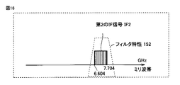
IF帯バンドパスフィルタ55は、IF多重信号から第2のIF信号IF2を抽出する。図13および図16に示すように、フィルタ特性152の通過特性をもつIF帯バンドパスフィルタ55によって第2のIF信号IF2が抽出される。第2のIF信号IF2は、IFアンプ58で増幅され、さらに減衰器(T5)60で適宜レベル調整されて、IF帯ミキサ64に送られる。
The IF band-
IF帯ミキサ63は、第1のIF信号IF1を基準信号IFstdで第2の周波数ダウンコンバ−トして、周波数fbb1の第1のベースバンド信号bb1を生成する。 The IF band mixer 63 down-converts the first IF signal IF1 with the reference signal IFstd by the second frequency to generate the first baseband signal bb1 having the frequency fbb1.
IF帯ミキサ64は、第2のIF信号IF2を基準信号IFstdで第3の周波数ダウンコンバ−トして、周波数fbb2の第2のベ−スンバンド信号bb2を生成する。 The IF band mixer 64 down-converts the second IF signal IF2 with the reference signal IFstd for a third frequency to generate a second baseband signal bb2 having the frequency fbb2.
図17は、第1のベ−スバンド信号bb1の周波数スペクトル示す図である。第1のベースバンド信号bb1は、図2に示す第1の変調信号bb1と、周波数、周波数安定度や位相雑音特性は同等な信号である。 FIG. 17 is a diagram illustrating a frequency spectrum of the first baseband signal bb1. The first baseband signal bb1 is a signal having the same frequency, frequency stability, and phase noise characteristics as the first modulation signal bb1 shown in FIG.
図18は、第2のベ−スバンド信号bb2の周波数スペクトルを示す図である。第2のベ−スバンド信号bb2は、図7に示す第2の変調信号bb2と、周波数、周波数安定度や位相雑音特性は同等な信号である。 FIG. 18 is a diagram illustrating a frequency spectrum of the second baseband signal bb2. The second baseband signal bb2 is a signal having the same frequency, frequency stability, and phase noise characteristics as the second modulated signal bb2 shown in FIG.
上述の処理において、周波数関係は以下のように表わされる。
<第1のミリ波変調信号RF1の第1のダウンコンバ−ト>
fRF1−6×frlo=fIF1・・・(11)
式(11)は、式(7)によって以下のように変形できる。
(11×fstd−fbb1)−6×frlo=fIF1・・・(12)
<第2のミリ波変調信号RF2の第1のダウンコンバート>
fRF2−6×frlo=fIF2・・・(13)
式(13)は、式(9)によって以下のように変形できる。
(11×fstd+fbb2)−6×frlo=fIF2・・・(14)
<ミリ波基準信号RFstdの第1のダウンコンバート>
fRFstd−6×frlo=fIFstd・・・(15)
式(15)は、式(10)によって以下のように変形できる。
In the above processing, the frequency relationship is expressed as follows.
<First down-conversion of first millimeter-wave modulation signal RF1>
fRF1-6 × frlo = fIF1 (11)
Equation (11) can be transformed as follows by Equation (7).
(11 × fstd−fbb1) −6 × frlo = fIF1 (12)
<First down-conversion of second millimeter-wave modulation signal RF2>
fRF2-6 × frlo = fIF2 (13)
Equation (13) can be transformed as follows by Equation (9).
(11 × fstd + fbb2) −6 × frlo = fIF2 (14)
<First down-conversion of millimeter wave reference signal RFstd>
fRFstd−6 × frlo = fIFstd (15)
Equation (15) can be transformed as follows by Equation (10).
11×fstd−6×frlo=fIFstd・・・(16)
<第1のIF信号IF1の第2のダウンコンバート>
第2のダウンコンバ−トは、fIFstd>fIF1の関係によって、以下のように表わされる。
11 × fstd−6 × frlo = fIFstd (16)
<Second down-conversion of the first IF signal IF1>
The second down-conversion is expressed as follows by the relationship of fIFstd> fIF1.
fIFstd−fIF1=fbb1・・・(17)
<第2のIF信号IF2の第3のダウンコンバート>
第3のダウンコンバ−トは、fIFstd<fIF2の関係によって、以下のように表わされる。
fIFstd−fIF1 = fbb1 (17)
<Third down-conversion of second IF signal IF2>
The third down-conversion is expressed as follows by the relationship of fIFstd <fIF2.
fIF2−fIFstd=fbb2・・・(18)
この関係から明らかなように、ミリ波受信装置40か出力される第1のベースバンド信号bb1及び第2のベースバンド信号bb2は、ミリ波送信装置193の第1の入力信号であるbb1、第2の入力信号であるbb2となり、周波数、周波数安定度や位相雑音特性は送信入力信号と同等な信号が生成される。
fIF2-fIFstd = fbb2 (18)
As is clear from this relationship, the first baseband signal bb1 and the second baseband signal bb2 output from the millimeter
図10に示すミリ波受信装置40においては、ベ−スバンド回路43では、生成された第1のベースバンド信号bb1、第2のベースバンド信号bb2は、夫々減衰器73、減衰器70、及びフィルタ74、71及びアンプ75、72でレベル調整と不要波信号が除去された後、スイッチ76に入力される。TV92や録画機93からは、チャンネル切り替えるための制御信号94により、受信装置40中のスイッチSW76で選択され、出力される。
In the millimeter
上述のミリ波受信装置40では、第2の実施形態のミリ波送信装置192の信号を受信する受信装置として説明したが、第1の実施形態のミリ波送信装置1の信号を受信する受信装置としてもでもそのまま使用することができることができる。さらに、IF回路42のIF帯バンドパスフィルタ54、55、56の通過特性を適宜変更することにより、受信感度のより高い第1の実施の形態専用の受信装置とすることも可能である。
In the above-described millimeter
今回開示された実施の形態はすべての点で例示であって制限的なものではないと考えられるべきである。本発明の範囲は上記した説明ではなくて特許請求の範囲によって示され、特許請求の範囲と均等の意味および範囲内でのすべての変更が含まれることが意図される。 The embodiment disclosed this time should be considered as illustrative in all points and not restrictive. The scope of the present invention is defined by the terms of the claims, rather than the description above, and is intended to include any modifications within the scope and meaning equivalent to the terms of the claims.
1,192 ミリ波送信装置、2,2a,2b,43 ベースバンド回路、3,38a,38b,42 IF回路、4,41 ミリ波ICモジュール、6,10,10a,10b,12,12a,12b,14b,96,37a,37b,34,50,52,57,58,61,62,75 アンプ、7,97 リミタ、8,8a,8b,32a,32b,44,63,64 ミキサ、9,9a,9b,33,49,54,55,56,71,74 バンドパスフィルタ、13A,13B,13C 端子、14,14a 増幅分配部、15 基準信号源、16,46 整合器、11,11a,11b,17,17a,70,73 減衰器、29,39 電力合成器、35,51 アンテナ、36 M逓倍型マルチプライア、40 ミリ波受信装置、45 N逓倍器+バッファアンプ、48 DRO型発振器、76 スイッチ、191,193 75/50Ω変換部。 1,192 mm-wave transmitter, 2, 2a, 2b, 43 baseband circuit, 3, 38a, 38b, 42 IF circuit, 4, 41 mm-wave IC module, 6, 10, 10a, 10b, 12, 12a, 12b , 14b, 96, 37a, 37b, 34, 50, 52, 57, 58, 61, 62, 75 Amplifier, 7, 97 Limiter, 8, 8a, 8b, 32a, 32b, 44, 63, 64 Mixer, 9a, 9b, 33, 49, 54, 55, 56, 71, 74 Band-pass filter, 13A, 13B, 13C terminals, 14, 14a Amplifying distributor, 15 Reference signal source, 16, 46 Matching unit, 11, 11a, 11b, 17, 17a, 70, 73 Attenuator, 29, 39 Power combiner, 35, 51 Antenna, 36 M multiplier, 40 Millimeter wave receiver, 45 Multiplier + buffer amplifier, 48 DRO oscillator, 76 switch, 191, 193 75/50 [Omega conversion unit.
Claims (13)
前記逓倍基準信号に基づいて、前記基準信号によって周波数変換された中間周波数信号をミリ波帯へアップコンバートするミリ波帯第1ミキサと、
前記逓倍基準信号に基づいて、前記基準信号をミリ波帯へアップコンバートするミリ波帯第2ミキサと、
前記ミリ波帯第1ミキサおよび前記ミリ波帯第2ミキサでアップコンバ−トされた信号を合成してミリ波多重信号を生成するミリ波帯合成部とを備えたミリ波送信モジュール。 A multiplier for generating a multiplied reference signal obtained by multiplying the reference signal;
A first millimeter-wave band mixer that up-converts an intermediate frequency signal frequency-converted by the reference signal into a millimeter-wave band based on the multiplied reference signal;
A second millimeter-wave band mixer that up-converts the reference signal into a millimeter-wave band based on the multiplied reference signal;
A millimeter-wave transmission module comprising a millimeter-wave band synthesizer that synthesizes signals up-converted by the millimeter-wave band first mixer and the millimeter-wave band second mixer to generate a millimeter-wave multiplexed signal.
前記基準信号に基づいて、ベースバンド信号を中間周波数信号にアップコンバートするIF帯ミキサと、
前記基準信号源から出力された基準信号を逓倍した逓倍基準信号を生成する逓倍器と、
前記逓倍基準信号に基づいて、前記中間周波数信号をミリ波帯へアップコンバートするミリ波帯第1ミキサと、
前記逓倍基準信号に基づいて、前記基準信号源から出力された基準信号をミリ波帯へアップコンバートするミリ波帯第2ミキサと、
前記ミリ波帯第1ミキサおよび前記ミリ波帯第2ミキサでアップコンバ−トされた信号を合成してミリ波多重信号を生成するミリ波帯合成部とを備えたミリ波送信装置。 A reference signal source for outputting a reference signal;
An IF band mixer that upconverts a baseband signal to an intermediate frequency signal based on the reference signal;
A multiplier for generating a multiplied reference signal obtained by multiplying the reference signal output from the reference signal source;
A first millimeter-wave band mixer that up-converts the intermediate frequency signal into a millimeter-wave band based on the multiplied reference signal;
A millimeter-wave band second mixer for up-converting the reference signal output from the reference signal source to the millimeter-wave band based on the multiplied reference signal;
A millimeter-wave transmitter comprising: a millimeter-wave band synthesizer that synthesizes signals up-converted by the millimeter-wave band first mixer and the millimeter-wave band second mixer to generate a millimeter-wave multiplexed signal.
前記基準信号に基づいて、第1のベースバンド信号を第1の中間周波数信号にアップコンバートするIF帯第1ミキサと、
前記基準信号に基づいて、第2のベースバンド信号を第2の中間周波数信号にアップコンバートするIF帯第2ミキサと、
前記第1の中間周波数信号および前記第2の中間周波数信号を合成するIF帯合成部と、
前記基準信号源から出力された基準信号を逓倍した逓倍基準信号を生成する逓倍器と、
前記逓倍基準信号に基づいて、前記合成された中間周波数信号をミリ波帯へアップコンバートするミリ波帯第1ミキサと、
前記逓倍基準信号に基づいて、前記基準信号源から出力された基準信号をミリ波帯へアップコンバートするミリ波帯第2ミキサと、
前記ミリ波帯第1ミキサおよび前記ミリ波帯第2ミキサでアップコンバ−トされた信号を合成してミリ波多重信号を生成するミリ波帯合成部とを備えたミリ波送信装置。 A reference signal source for outputting a reference signal;
An IF band first mixer that up-converts a first baseband signal into a first intermediate frequency signal based on the reference signal;
An IF band second mixer for up-converting a second baseband signal to a second intermediate frequency signal based on the reference signal;
An IF band synthesizing unit that synthesizes the first intermediate frequency signal and the second intermediate frequency signal;
A multiplier for generating a multiplied reference signal obtained by multiplying the reference signal output from the reference signal source;
A first millimeter-wave band mixer that up-converts the synthesized intermediate frequency signal into a millimeter-wave band based on the multiplied reference signal;
A millimeter-wave band second mixer for up-converting the reference signal output from the reference signal source to the millimeter-wave band based on the multiplied reference signal;
A millimeter-wave transmitter comprising: a millimeter-wave band synthesizer that synthesizes signals up-converted by the millimeter-wave band first mixer and the millimeter-wave band second mixer to generate a millimeter-wave multiplexed signal.
前記IF帯第2ミキサから出力される第2の中間周波数信号の下側波帯を通すIF帯第2バンドパスフィルタとを備える、請求項9記載のミリ波送信装置。 An IF band first bandpass filter that passes a lower sideband of the first intermediate frequency signal output from the IF band first mixer;
The millimeter wave transmission apparatus according to claim 9, further comprising an IF band second band pass filter that passes a lower side band of the second intermediate frequency signal output from the IF band second mixer.
Priority Applications (1)
| Application Number | Priority Date | Filing Date | Title |
|---|---|---|---|
| JP2012157368A JP6009251B2 (en) | 2012-07-13 | 2012-07-13 | Millimeter wave transmission module and millimeter wave transmission device |
Applications Claiming Priority (1)
| Application Number | Priority Date | Filing Date | Title |
|---|---|---|---|
| JP2012157368A JP6009251B2 (en) | 2012-07-13 | 2012-07-13 | Millimeter wave transmission module and millimeter wave transmission device |
Publications (2)
| Publication Number | Publication Date |
|---|---|
| JP2014022812A JP2014022812A (en) | 2014-02-03 |
| JP6009251B2 true JP6009251B2 (en) | 2016-10-19 |
Family
ID=50197282
Family Applications (1)
| Application Number | Title | Priority Date | Filing Date |
|---|---|---|---|
| JP2012157368A Expired - Fee Related JP6009251B2 (en) | 2012-07-13 | 2012-07-13 | Millimeter wave transmission module and millimeter wave transmission device |
Country Status (1)
| Country | Link |
|---|---|
| JP (1) | JP6009251B2 (en) |
Families Citing this family (7)
| Publication number | Priority date | Publication date | Assignee | Title |
|---|---|---|---|---|
| US9565675B2 (en) * | 2014-09-26 | 2017-02-07 | Hughes Network Systems L.L.C. | Fixed intermediate frequency signal with tuned low frequency local oscillator reference for linear transmitter |
| CN106533365B (en) * | 2016-11-16 | 2019-07-30 | 中国电子科技集团公司第四十一研究所 | A kind of efficient broadband integrates the T shape Terahertz frequency mixer of local oscillator |
| CN109462414A (en) * | 2018-09-29 | 2019-03-12 | 扬州海科电子科技有限公司 | A kind of 18-30GHz front end receiver component |
| CN111355499B (en) * | 2018-12-24 | 2023-12-12 | 深圳市华讯方舟光电技术有限公司 | Radio frequency link |
| CN109861646B (en) * | 2018-12-29 | 2022-11-25 | 北京航天测控技术有限公司 | Broadband millimeter wave up-conversion method |
| CN112751577B (en) * | 2020-12-30 | 2022-07-19 | 中电科思仪科技(安徽)有限公司 | Ultra-wideband millimeter wave up-conversion transmitting device and method |
| CN114978331B (en) * | 2022-05-16 | 2023-06-06 | 中国空间技术研究院 | Microwave millimeter wave signal transmitting system based on optical heterodyne |
Family Cites Families (8)
| Publication number | Priority date | Publication date | Assignee | Title |
|---|---|---|---|---|
| JP2595783B2 (en) * | 1990-07-31 | 1997-04-02 | 日本電気株式会社 | Transmitter |
| JP3876154B2 (en) * | 2001-11-27 | 2007-01-31 | シャープ株式会社 | Millimeter-wave wireless transmitter, millimeter-wave wireless receiver, and millimeter-wave communication system |
| JP3992222B2 (en) * | 2002-02-27 | 2007-10-17 | 独立行政法人情報通信研究機構 | Transmitter, transmission method, receiver, reception method, radio communication apparatus, and radio communication method |
| JP4630990B2 (en) * | 2005-12-06 | 2011-02-09 | 独立行政法人情報通信研究機構 | Two-way wireless communication device |
| JP2007180621A (en) * | 2005-12-26 | 2007-07-12 | National Institute Of Information & Communication Technology | Frequency converter and frequency conversion method |
| JP4699336B2 (en) * | 2006-10-31 | 2011-06-08 | シャープ株式会社 | Wireless receiver and electronic device |
| JP5004191B2 (en) * | 2008-09-16 | 2012-08-22 | シャープ株式会社 | Millimeter wave transmission / reception system |
| JP5085499B2 (en) * | 2008-10-10 | 2012-11-28 | 株式会社東芝 | Wireless communication method, system, wireless transmitter and wireless receiver |
-
2012
- 2012-07-13 JP JP2012157368A patent/JP6009251B2/en not_active Expired - Fee Related
Also Published As
| Publication number | Publication date |
|---|---|
| JP2014022812A (en) | 2014-02-03 |
Similar Documents
| Publication | Publication Date | Title |
|---|---|---|
| JP6009251B2 (en) | Millimeter wave transmission module and millimeter wave transmission device | |
| JP2001053640A (en) | Device and method for radio communication | |
| EP1225715B1 (en) | Transmitter, receiver, and method | |
| JP4138758B2 (en) | Wireless receiver, wireless communication system, and electronic device | |
| JP3876154B2 (en) | Millimeter-wave wireless transmitter, millimeter-wave wireless receiver, and millimeter-wave communication system | |
| JP4423251B2 (en) | Wireless receiver | |
| JP2003179516A (en) | Radio communication system, radio transmitter, and radio receiver | |
| KR100714699B1 (en) | Wireless transceiver supporting plurality of communication/broadcast service | |
| US20140334635A1 (en) | 7GHz Professional Wireless Microphone System | |
| CN112514245A (en) | Broadband millimeter wave front end integrated circuit | |
| JP4699336B2 (en) | Wireless receiver and electronic device | |
| JPWO2003073628A1 (en) | Microwave band wireless transmitter, microwave band wireless receiver, and microwave band wireless communication system | |
| JP3992222B2 (en) | Transmitter, transmission method, receiver, reception method, radio communication apparatus, and radio communication method | |
| JP2007180621A (en) | Frequency converter and frequency conversion method | |
| JP5808644B2 (en) | Receiving apparatus and communication system | |
| JP2011250093A (en) | Receiver and transmitter | |
| EP1717948B1 (en) | Wideband phase shift device | |
| JP4411302B2 (en) | Multiband transceiver | |
| JP4486608B2 (en) | Microwave band radio transmitter, microwave band radio receiver and microwave band radio transceiver system | |
| JP4250125B2 (en) | Wireless transmission device | |
| JP4074807B2 (en) | Millimeter-wave transmission / reception system, transmission device, and reception device | |
| JP4142938B2 (en) | Millimeter-wave transmission / reception system, transmission device, and reception device | |
| JP5215082B2 (en) | Millimeter wave transmitter and millimeter wave transceiver system | |
| JP2004173111A (en) | Millimeter-wave band transceiver system, transmitter and receiver | |
| JP4608092B2 (en) | CATV system, down converter and up converter |
Legal Events
| Date | Code | Title | Description |
|---|---|---|---|
| A621 | Written request for application examination |
Free format text: JAPANESE INTERMEDIATE CODE: A621 Effective date: 20150701 |
|
| A977 | Report on retrieval |
Free format text: JAPANESE INTERMEDIATE CODE: A971007 Effective date: 20160506 |
|
| A131 | Notification of reasons for refusal |
Free format text: JAPANESE INTERMEDIATE CODE: A131 Effective date: 20160614 |
|
| A521 | Request for written amendment filed |
Free format text: JAPANESE INTERMEDIATE CODE: A523 Effective date: 20160802 |
|
| TRDD | Decision of grant or rejection written | ||
| A01 | Written decision to grant a patent or to grant a registration (utility model) |
Free format text: JAPANESE INTERMEDIATE CODE: A01 Effective date: 20160823 |
|
| A61 | First payment of annual fees (during grant procedure) |
Free format text: JAPANESE INTERMEDIATE CODE: A61 Effective date: 20160914 |
|
| R150 | Certificate of patent or registration of utility model |
Ref document number: 6009251 Country of ref document: JP Free format text: JAPANESE INTERMEDIATE CODE: R150 |
|
| LAPS | Cancellation because of no payment of annual fees |