JP6005265B2 - Electric vehicle power supply equipment cable detection - Google Patents
Electric vehicle power supply equipment cable detection Download PDFInfo
- Publication number
- JP6005265B2 JP6005265B2 JP2015515114A JP2015515114A JP6005265B2 JP 6005265 B2 JP6005265 B2 JP 6005265B2 JP 2015515114 A JP2015515114 A JP 2015515114A JP 2015515114 A JP2015515114 A JP 2015515114A JP 6005265 B2 JP6005265 B2 JP 6005265B2
- Authority
- JP
- Japan
- Prior art keywords
- cable
- electric vehicle
- voltage
- power supply
- line
- Prior art date
- Legal status (The legal status is an assumption and is not a legal conclusion. Google has not performed a legal analysis and makes no representation as to the accuracy of the status listed.)
- Active
Links
Images


Classifications
-
- G—PHYSICS
- G08—SIGNALLING
- G08B—SIGNALLING OR CALLING SYSTEMS; ORDER TELEGRAPHS; ALARM SYSTEMS
- G08B13/00—Burglar, theft or intruder alarms
- G08B13/02—Mechanical actuation
- G08B13/14—Mechanical actuation by lifting or attempted removal of hand-portable articles
- G08B13/1409—Mechanical actuation by lifting or attempted removal of hand-portable articles for removal detection of electrical appliances by detecting their physical disconnection from an electrical system, e.g. using a switch incorporated in the plug connector
- G08B13/1418—Removal detected by failure in electrical connection between the appliance and a control centre, home control panel or a power supply
Description
本出願は、2012年5月30日に「電気自動車給電設備ケーブル検知」の名称で出願された米国特許出願第13/483,433号からの優先権を主張する。この出願明細書の全体を、参照により本明細書に援用する。 This application claims priority from US patent application Ser. No. 13 / 483,433, filed May 30, 2012 under the name “Electric Vehicle Feeder Cable Detection”. This entire application is hereby incorporated by reference.
本開示は、一般的に電気自動車給電設備のケーブルの状態の検知、特に、電気自動車給電設備からのケーブルの盗難の検知に関する。 The present disclosure relates generally to the detection of the state of a cable in an electric vehicle power supply facility, and more particularly to the detection of a cable theft from an electric vehicle power supply facility.
地球規模での化石燃料への依存を減らそうとする願望が大きくなるにつれて、給電設備の需要が大きくなっている。電気モータに関連する技術が進歩するとともに、より多くの電気モータが燃焼エンジンを置換している。この影響はすでに自動車業界で始まっている。今日、ハイブリッド車や電気自動車が次第に普及してきている。したがって、これらの車両に電力を供給する需要が高まっている。 As the desire to reduce reliance on fossil fuels on a global scale increases, the demand for power supply facilities has increased. As technology related to electric motors advances, more electric motors are replacing combustion engines. This effect has already begun in the automotive industry. Today, hybrid vehicles and electric vehicles are becoming increasingly popular. Therefore, the demand for supplying electric power to these vehicles is increasing.
この需要を満たすために、個人や法人が充電ステーションとも呼ばれる電気自動車給電設備(EVSE)の生産や導入を増やしている。この装置は、部品の中でも特に、電力供給源から電気自動車まで供給電力を運ぶためのケーブル(コードセットとも呼ばれる)を含むのが一般的である。この機能を実行するために、ケーブルは、通常、断面積の大きな銅製の導体を用いて製造される。なぜならば、通常、銅製の導体は、電気自動車の充電に必要とされる電力を運ぶために通常は適しているからである。 To meet this demand, individuals and corporations are increasing the production and introduction of electric vehicle power supply equipment (EVSE), also called charging stations. The device typically includes, among other components, a cable (also referred to as a cord set) for carrying the supplied power from the power supply to the electric vehicle. In order to perform this function, the cable is usually manufactured using a copper conductor with a large cross-sectional area. This is because copper conductors are usually suitable for carrying the power required to charge an electric vehicle.
ユーザの便益のために、これらのケーブルは、EVSEから電気自動車まで延在するように、数フィート又は数メーターの長さである。すなわち、ユーザの車両に十分届く長さにケーブルが設計されているので、ユーザは自分の車両を充電することができる。したがって、ケーブルは、銅のような高価な導体材料を多量に含みうる。したがって、EVSEのケーブルは盗難の対象となりうる。 For the benefit of the user, these cables are several feet or meters long to extend from the EVSE to the electric vehicle. That is, since the cable is designed to be long enough to reach the user's vehicle, the user can charge his / her vehicle. Thus, the cable may contain a large amount of expensive conductor material such as copper. Therefore, EVSE cables can be subject to theft.
さらに、EVSEは多数の場所に導入されうるので、とりわけ盗難を受けやすい。すなわち、EVSEは、集中させるのではなく、広大なエリアにわたって分散されている。したがって、オーナーやオペレータが複数のEVSEを監視することは特に難しくなりうる。 In addition, EVSE is particularly vulnerable to theft because it can be deployed in many locations. That is, EVSE is not concentrated but distributed over a vast area. Therefore, it can be particularly difficult for an owner or operator to monitor multiple EVSEs.
したがって、EVSEのような給電設備をケーブルの盗難から保護するとともに、この設備のユーザ利便性、安全性、所有コストを改善する新規なシステム及び手法が要求されている。 Therefore, there is a need for a new system and method that protects power supply equipment such as EVSE from cable theft and improves the user convenience, safety, and cost of ownership of this equipment.
上述の背景に照らして、本発明のいくつかの態様係る基礎的な理解を提供するために、以下、本開示の簡単な概要を示す。この概要は、本発明の広範囲にわたる全体像ではない。この概要は、本発明の鍵となる要素や重要な要素を特定し、本発明の範囲を限定することを意図するものではない。以下の概要は単に、以下に提供されるより詳細な説明への前段として、簡易化した形式で本発明のいくつかの概念を示している。 In order to provide a basic understanding of some aspects of the invention in light of the above background, a brief summary of the disclosure is provided below. This summary is not an extensive overview of the invention. This summary is not intended to identify key or critical elements of the invention and to limit the scope of the invention. The following summary merely presents some concepts of the invention in a simplified form as a prelude to the more detailed description provided below.
従来技術において、EVSEケーブル端部のEVSEコネクタ(例えば、「SAE推奨法であるJ1772、SAE電気自動車及びプラグインハイブリッド電気自動車用導通充電カプラ」(以下、SAE J1772)に規定される、電源線L1及びL2/N、接地線、並びにコントロールパイロット線を含むコネクタ)のピンは、電気自動車に接続されていない場合、全てオープン(開路)であるので、EVSEのケーブルの盗難を検知することは難しい。言い換えれば、ケーブルが電気自動車に接続されていない場合には、ケーブルを含めて、閉回路が形成されていないので、EVSEケーブルの盗難の検知は非現実的である。したがって、この開示は、コネクタ部に特注のハードウェアを必要としないEVSEによってケーブルの盗難を検知できるという利益をもたらす。例えば、本開示は、EVSE制御ボックスに含まれるケーブル検知副回路にまで近接線を延在させることによって、SAE J1772に規定されるEVSEコネクタを用いてケーブルの盗難を検知する手法を提供する。さらに、この開示は、最小限のハードウェア要求とコストでEVSEケーブルの盗難検知の解決策を提供する。 In the prior art, the power line L1 defined in the EVSE connector at the end of the EVSE cable (for example, “SAE recommended method J1772, SAE electric vehicle and plug-in hybrid electric vehicle conduction charging coupler” (hereinafter referred to as SAE J1772)) And L2 / N, the connector of the ground line, and the connector including the control pilot line) are all open (open circuit) when not connected to the electric vehicle, it is difficult to detect the EVSE cable theft. In other words, when the cable is not connected to the electric vehicle, since the closed circuit including the cable is not formed, the detection of theft of the EVSE cable is unrealistic. Accordingly, this disclosure provides the benefit that cable theft can be detected by EVSE that does not require custom hardware in the connector section. For example, the present disclosure provides a technique for detecting cable theft using the EVSE connector defined in SAE J1772 by extending a proximity line to the cable detection subcircuit included in the EVSE control box. Further, this disclosure provides an EVSE cable theft detection solution with minimal hardware requirements and cost.
本開示の態様は、改善された給電設備を提供するための方法、コンピュータ可読媒体、及び装置を開示することにより、上述の課題のうちの1つ以上に取り組む。さらに、本開示の態様は、それ自身のケーブルの状態を検知しうる給電設備を提供する。例えば、給電設備は、ケーブルが給電設備に接続されたままかどうか、又は、ケーブルが取り去られてしまったかどうか検知する。何者かが、給電設備からケーブルを切断したり、引き抜いたり、さもなければ取り去ったりする可能性が予測される。したがって、ここで開示される給電設備は、ケーブルが盗難されたかどうか検知することができ、したがって、本開示の給電設備は盗難を予防または阻止できる。 Aspects of the present disclosure address one or more of the above issues by disclosing methods, computer readable media, and apparatus for providing an improved power supply facility. Furthermore, aspects of the present disclosure provide a power supply facility that can detect the state of its own cable. For example, the power supply facility detects whether the cable remains connected to the power supply facility or whether the cable has been removed. It is anticipated that someone may cut, pull, or otherwise remove the cable from the power supply facility. Accordingly, the power supply facility disclosed herein can detect whether the cable has been stolen, and thus the power supply facility of the present disclosure can prevent or prevent theft.
本開示のいくつかの態様において、ケーブルが取り去られた場合、給電設備は取り去られた時刻を検知できる。加えて、給電設備は、ケーブルが取り去られたことを検知したことに対応するきっかけとなりうる。様々な対応がここで開示される。 In some aspects of the present disclosure, when the cable is removed, the feed facility can detect the time of removal. In addition, the power supply facility can be a trigger for detecting that the cable has been removed. Various correspondences are disclosed herein.
さらに、本開示のいくつかの態様において、給電設備は、電気自動車に電力を供給するための電気自動車給電設備である。電気自動車給電設備は、電気自動車に電力を供給するために用いられるケーブルの盗難を予防または阻止できる。したがって、本開示の電気自動車給電設備は、ケーブルの盗難に対抗する手動の保護手段、及び/又は、ケーブルの盗難に対抗するその他のコストがかかる保護手段の代替物を提供しうる。 Further, in some aspects of the present disclosure, the power supply facility is an electric vehicle power supply facility for supplying electric power to the electric vehicle. The electric vehicle power supply facility can prevent or prevent theft of a cable used to supply electric power to the electric vehicle. Accordingly, the electric vehicle power supply facilities of the present disclosure may provide an alternative to manual protection measures against cable theft and / or other costly protection measures against cable theft.
本開示は、電気自動車給電設備のような給電設備に実装されるケーブル検知副回路を開示する。ケーブル検知副回路は、自動的にケーブルの状態を検知しうる。ケーブル検知副回路は、ケーブルに延在する導体に電流を流し、閉回路ループが存在するかどうか判定することによって、状態を検知しうる。閉回路ループが存在する場合、ケーブル検知副回路はケーブルがそのまま残っていることを示す信号を出力しうる。対して、閉回路ループが存在しない場合、ケーブル検知副回路はケーブルが取り去られたことを示す信号を出力しうる。 The present disclosure discloses a cable detection subcircuit implemented in a power supply facility such as an electric vehicle power supply facility. The cable detection subcircuit can automatically detect the cable status. The cable detection subcircuit may detect the condition by passing current through a conductor extending through the cable and determining whether a closed circuit loop exists. If a closed circuit loop exists, the cable detection subcircuit may output a signal indicating that the cable remains intact. On the other hand, if there is no closed circuit loop, the cable detection subcircuit may output a signal indicating that the cable has been removed.
もちろん、上記で言及される実施形態の方法及びシステムは、その他の追加的な要素、ステップ、コンピュータ実行可能な命令、又はコンピュータ可読なデータ構造を含みうる。この点において、他の実施形態も明細書及び特許請求の範囲に記載される。本開示のこれら及び他の実施形態の詳細は、添付の図面及び以下の説明において示されている。本発明のその他の特徴及び利点は説明や図面から明白であるし、特許請求の範囲からも明白であろう。 Of course, the methods and systems of the embodiments referred to above may include other additional elements, steps, computer-executable instructions, or computer-readable data structures. In this respect, other embodiments are described in the specification and claims. The details of these and other embodiments of the disclosure are set forth in the accompanying drawings and the description below. Other features and advantages of the invention will be apparent from the description and drawings, and from the claims.
本開示は例示的な説明であり、添付した図面に限定されない。図面において、類似の参照符号は類似の要素を示している。本開示の様々な態様によれば、給電設備のケーブルの状態を検知するために、方法、コンピュータ可読媒体、及び装置が開示される。ここで、ケーブルの状態とは、ケーブルの状況を意味し、ケーブルがそのまま残っているか、取り去られたか、損傷しているか、などを示しうる。さらに、ケーブルが取り去られていると記載されている場合、取り去られるには、切断、引き抜き、取り外しなどのような任意の手段による取り去りを含みうる。また、場合によっては、ケーブルはそのいずれかの部分が取り去られた場合も取り去られたとみなされうる。すなわち、ケーブルはその一部分が切り取られた場合も取り去られたとして記載されうる。 The present disclosure is an exemplary description and is not limited to the attached drawings. In the drawings, like reference numerals indicate like elements. In accordance with various aspects of the present disclosure, a method, computer readable medium, and apparatus are disclosed for detecting a condition of a power supply facility cable. Here, the state of the cable means the state of the cable and can indicate whether the cable remains as it is, removed, damaged, or the like. Further, if the cable is described as being removed, removal may include removal by any means such as cutting, pulling, removing, and the like. Also, in some cases, a cable may be considered removed if any part thereof is removed. That is, the cable can be described as removed if a portion of it is cut.
この開示は、給電設備及びそのケーブル検知副回路の種々の実施形態について網羅的に説明しているわけではない。ここでは、給電設備の例示的実施形態は、電気自動車給電設備に関連する。しかしながら、本開示の態様は他のタイプの給電設備、特に、電気自動車給電設備の場合と同様に、高価な銅製の導体で作られたケーブルを含む装置に対して適用可能であることが理解されるべきである。 This disclosure is not an exhaustive description of various embodiments of the feed facility and its cable detection subcircuit. Here, an exemplary embodiment of a power supply facility relates to an electric vehicle power supply facility. However, it is understood that aspects of the present disclosure are applicable to other types of power supply equipment, particularly devices including cables made of expensive copper conductors, as is the case with electric vehicle power supply equipment. Should be.
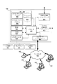
図1は、本開示の一態様にしたがう電気自動車給電設備の構成例を示す図である。より具体的には、図1は、給電設備の一種である電気自動車給電設備(EVSE)100の構成例を説明している。図1はEVSE100の全ての構成部品を示しているわけではなく、代わりに、SAE J1772に規定されるようなEVSE100のいくつかの基本的な構成部品に焦点を合わせていることが理解されるべきである。さらに、図1は、電気自動車101に接続され、電気自動車101を充電している状態でEVSE100を示している。したがって、EVSE100のいくつかの基本的な構成部品を示すことに加えて、図1は、電気自動車101のいくつかの基本的な構成部品も示している。
FIG. 1 is a diagram illustrating a configuration example of an electric vehicle power supply facility according to an aspect of the present disclosure. More specifically, FIG. 1 illustrates a configuration example of an electric vehicle power supply facility (EVSE) 100 that is a kind of power supply facility. It should be understood that FIG. 1 does not show all the components of
図1に示すように、EVSE100は、EVSE制御ボックス102、EVSEコネクタ(すなわちプラグ)103、及びEVSE制御ボックス102をEVSEコネクタ103に接続するケーブル104を備える。ケーブル104は、EVSE制御ボックス102及び/又はEVSEコネクタ103に固定的に、又は取り外し可能に接続されうる。安全又は規制の観点からは、ケーブル104をEVSE制御ボックス102及びEVSEコネクタ103に固定的に接続することが望ましいであろう。一方、種々の理由(例えば、より経済的であったり、より固定しやすかったりすること)により、ケーブル104をEVSE制御ボックス102及び/又はEVSEコネクタ103から容易に取り外せることが望ましいであろう。例えば、ケーブル104が欠陥を有する(例えば、絶縁体が損傷している、導体中に不連続が存在する、など)と判断された場合に、ケーブル104は取り去られ、新しいケーブルに交換されうる。したがって、EVSE100全体を交換することなく、ケーブル104が交換されうる。一方、EVSEコネクタ103は、1つ以上の電気自動車101の車両コネクタ(例えば車両のインレット)105に取り外し可能に接続されるように構成される。すなわち、EVSEコネクタ103は、複数の電気自動車101に接続できるように、関連する基準にしたがうべきである。基準の非限定的な例は、SAE J1772である。
As shown in FIG. 1, the
従来技術において、EVSEコネクタ103のピン(SAE J1772にしたがう)は、電気自動車101に接続されていない限り、全てオープン(開路)であるので、ケーブル104の盗難は検知が難しい。言い換えれば、ケーブル104を含めて、閉回路が形成されていない場合、EVSE100のケーブル104の盗難検知は非現実的である。したがって、この開示は、EVSEコネクタ103における専用のハードウェアを必要とせず、EVSE100によってケーブルの盗難検知をするという利益を提供する。例えば、本開示は、EVSE制御ボックス102に含まれる(以下、さらに詳細に説明される)ケーブル検知副回路まで近接線Pを延在することによって、EVSEコネクタ103を用いてケーブル104の盗難を検知する手段を提供する。さらに、この開示は、ハードウェア要求とコストを最小化しうる、EVSEケーブルの盗難検知の解決策を提供する。とりわけ、この開示は、基準が変化し、及び/又は、新しい基準が採用されうることも考慮しており、したがって、開示の態様はそれに応じて適応しうる。
In the prior art, the pins of the EVSE connector 103 (according to SAE J1772) are all open (open circuit) unless connected to the
上述のように、図1は、電力源がEVSE100から電気自動車101までケーブル104を通じて電流を流している実施形態を説明している。電力源は交流(AC)及び/又は直流(DC)の電力を供給しうる。また、電力源は種々なレベルの電力を供給するように構成されうる。例えば、電力源は120VAC及び/又は240VACを提供しうる。さらに、AC電力が供給される場合、交流周波数は種々の値(例えば60Hz、50Hz)でありうる。ケーブル104は、電力を送るための複数の導線を含みうる。図1に示すように、ケーブル104は、電流を運び電力を供給するための第1電力線L1及び第2電力線L2/Nを含みうる。図示されていないが、本開示に照らせば当業者によって理解されるだろういくつかの実施例において、ケーブル104は多相電力(例えば三相電力)を提供するために追加的なAC電力の導線を含みうる。加えて、ケーブル104は、充電中にEVSE100の装置接地端子を電気自動車101のシャーシの接地に連結する接地線Gndを含みうる。導線(すなわち、第1電力線L1、第2電力線L2/N、及び接地線Gnd)のそれぞれは、絶縁体に包まれた銅、アルミ、又はその他の導電材料を含みうる。3本の線は、第2の絶縁体により合わせて包まれうる。したがって、ユーザの視点からは、ケーブルは単一のワイヤであるように見えうる。いくつかの実施例において、ケーブル104は、制御パイロット線CP(以下更に詳細に論じられる)やDC電力線(図示されず)などのような追加的な導線も含みうる。
As described above, FIG. 1 illustrates an embodiment in which the power source conducts current through the
EVSE制御ボックス102とは、EVSE100の1つ以上の構成部品を収容する主要構造体のことである。EVSE制御ボックス102は、単一の構造体のように図示されるが、複数の分離した構造体の寄せ集めでありうる。EVSE制御ボックス102は、電力インジケータ115を含みうる。
The
さらに、EVSE制御ボックス102は、EVSE100への電力を断つための接触子106を含みうる。接触子106は、スイッチ(又はリレー)のように機能し、第1電力線L1及び第2電力線L2を通る、電流を流すための経路を開いたり閉じたりする。図1に示すように、接触子106は、電力源とケーブル104との間に配置され、したがって、電力源をケーブル104に接続したり切断したりするように動作する。接触子106が閉じた状態である場合、電流は電力源から第1電力線L1及び第2電力線L2を通ってケーブル104まで流れることができる。それに対して、接触子106が開いた状態である場合、電流は電力源からケーブル104まで流れることができない。さらに、接触子106は、第1電力線L1及び第2電力線L2の電力を断つことに特に適合しているので、ケーブル上の電荷が速やかにかつ安全に放散されうる。
Further, the
EVSE制御ボックス102は、接触子106を制御するための制御電子機器107も含む。より具体的には、制御電子機器107は、接触子106が開いた状態か閉じた状態か制御し、したがって、第1電力線L1及び第2電力線L2の電力を断つべき場合を制御する。制御電子機器107は、抵抗、キャパシタ、インダクタなどのような種々の回路部品を備えうるし、及び/又は、1つ以上の集積回路に実装されうる。いくつかの実施例において、制御電子機器107は、プリント回路基板(PCB)上に実装されうる。
The
加えて、EVSE制御ボックス102は、第1電力線L1及び第2電力線L2/Nの間の差動電流を検知するための漏電遮断機(GFI)108を含みうる。差動電流が閾値を越えた場合、GFIは制御電子機器107に、接触子106を開いた状態に切り替える対応をするように信号を送信しうる。
In addition, the
さらに、制御電子機器107は、監視回路109とも連動しうる。監視回路109は、制御パイロット信号を生成する制御パイロット線CPに連結されうる。図1に示されたような1つ以上の配置において、監視回路109は、スイッチ(S1)131及び抵抗(R1)132、並びに、パルス幅変調(PWM)信号生成器又は発振信号(例えばPWM信号)を生成するその他の発振器(図示せず)を含みうる。監視回路109は、制御パイロット線CPの電圧を監視しうる。検知された電圧に基づき、監視回路109及び制御電子機器107は、電気自動車101の状態を判定しうる。例えば、監視回路109及び制御電子機器107は、電気自動車101がEVSE100に接続されているかどうか、及び/又は、電気自動車101が充電準備状態にあるかどうか決定しうる。監視回路109は分離して示されているが、制御電子機器107に組み込まれてもよい。
Furthermore, the control
引き続き図1を参照して、EVSEコネクタ103は、EVSEコネクタ103を電気自動車101の車両コネクタ(例えば、車両のインレット)105に電気的に接続するように構成される5つの接点151−155を含みうる。接点151−155は、それぞれ第1電力線L1、第2電力線L2/N、接地線Gnd、制御パイロット線CP、及び近接回路への接続を提供しうる。いくつかの実施例において、5つの接点151−155のうち1つ以上の接点は、電気自動車101の車両コネクタ105に挿入されるように構成される突起(EVSEコネクタ103の基本構造から突き出している)を含みうる。車両コネクタ105は、接地線Gndと接点155の間に連結される抵抗(R5)161を含みうる。
With continued reference to FIG. 1,
さらに、EVSEコネクタ103は、近接回路を含みうる。近接回路は、車両コネクタ105におけるEVSEコネクタ103の存在を検知するために用いられうる。具体的には、電気自動車101は、近接線Pに信号を送り、近接回路のインピーダンスを検知することによって、EVSEコネクタ103が車両コネクタ105に接続されていることを検知しうる。したがって、近接回路から信号を受信したことに反応して、電気自動車101は充電の準備をしうる。多様な構成により近接回路を提供しうる。図1に示すように、近接回路は、互いに並列であるスイッチ(S3)134及び抵抗(R7)135の両方と直列に連結される抵抗(R6)133を含みうる。抵抗(R6)133の一端は、近接回路の接点155に連結されうる。一方、並列に接続されたスイッチ(S3)134及び抵抗(R7)135の一端は、接地線Gndに連結される。スイッチ(S3)134は、手動で(例えばユーザがボタンを押すことによって)、又は機械的に(例えばユーザがEVSEコネクタ103を車両コネクタ105に接続する場合にスライドするラッチによって)駆動されうる。1つ以上の配置において、スイッチ(S3)134は、EVSEコネクタ103が特定のコネクタ(例えば車両コネクタ105)に接続される場合にのみ閉じているように構成されうる。
Further, the
次に電気自動車101について、電気自動車101は多くの部品を含みうるが、図1は電気自動車の充電に関係するいくつかの部品のみを示している。具体的には、図1は、電気自動車101が、充電器181、バッテリ182、絶縁モニタ183、充電コントローラ184、充電状態インジケータ185、並びに抵抗(R2−R4)186−188、ダイオード(D)189、過渡電圧抑制ダイオード(TVS)190、スイッチ(S2)191及びバッファ192等の回路部品を含みうることを示している。
Next, with respect to the
図2は、EVSE200の他の実施例を示す。図2に示すように、EVSE200は、EVSE制御ボックス202、EVSEコネクタ203、及びケーブル204を含みうる。図2で、EVSE200は電気自動車201の電気自動車コネクタ205に電気的に接続されている。さらに、EVSE200は、第1電力線L1、第2電力線L2/N、制御パイロット線CP、近接線P、及び接地線Gndの5本の導線を含む。これら導線のそれぞれは、EVSEコネクタ203から出て、ケーブル204を通って、EVSEコネクタ203まで延在している。EVSEコネクタ203において、導線それぞれの一端は露出されている。すなわち、EVSEコネクタ203は、それぞれ5本の導線へのアクセスを可能にする5つの接点を含む。
FIG. 2 shows another embodiment of
一方、電気自動車コネクタ205は、EVSEコネクタ203の5つの接点にそれぞれ接続するように構成された5つの接点も含む。図2に示すように、電気自動車コネクタ205の5つの接点を通じて、電気自動車201は、EVSE200の5本の導線それぞれに電気的に接続しうる。
On the other hand, the
図2は、EVSE制御ボックス202が接触子(又はリレー)206、制御電子機器207、漏電遮断機(GFI)208、及びケーブル検知副回路225を含みうることも示している。図2に示すように、ケーブル検知副回路225は制御電子機器207、接地線Gnd、及びケーブル検知線に接続されうる。ここで、ケーブル検知線とは、ケーブル204を通り、閉回路ループを形成する目的でケーブル検知副回路225に連結されている任意の線を指す。図2では、ケーブル検知線は、近接線Pを介して電気自動車201に供給される信号と同じ信号を運ぶので、ケーブル検知線とは近接線Pを指す。
FIG. 2 also shows that the
とりわけ、工業規格(例えばSAE J1772参照)によれば、近接線Pの一部分(図2で破線により説明される)は、任意選択である。具体的には、SAE J1772のような工業規格に適合させるためにケーブル204又はEVSE制御ボックス202の中に近接線Pを含む必要はない。SAE J1772に適合させるために、近接線Pは、EVSEコネクタ203の中へ延在していることのみが必要であり、そこで近接回路に接続されている(図2で、必要な部分を近接線Pの実線部分により示す)。図1に関して上述されているように、近接回路は、EVSEコネクタ203が電気自動車コネクタ205に接続されていることを電気自動車201に知らせる目的で、EVSEコネクタ203に含まれる。図2で、EVSEコネクタ203の近接回路は、抵抗(R6)233及び抵抗(R7)235、並びにスイッチ(S3)234(図1における類似の参照要素に対応する)を含む。図1及び図2は、近接回路の類似の構成を示しているが、近接回路を他の構成で実施しうることを理解すべきである。
In particular, according to industry standards (see for example SAE J1772), a portion of the proximity line P (illustrated by the dashed line in FIG. 2) is optional. Specifically, it is not necessary to include proximity line P in
図2の例示的実施形態には、近接線Pの任意選択部分が含まれている。すなわち、近接線Pは、ケーブル204を通ってEVSE制御ボックス202の中まで延在し、そこでケーブル検知副回路225に電気的に接続されている。したがって、ケーブル検知副回路225は、ケーブル204の他端でEVSEコネクタ203の近接回路に接続されうる。さらに、ケーブル検知副回路225及び近接線は両方とも接地線Gndに接続されているので、閉回路ループが形成されうる。具体的には、この閉回路ループはケーブル検知副回路225、近接線P、近接回路、及び接地線Gndを含むであろう。
The exemplary embodiment of FIG. 2 includes an optional portion of the proximity line P. That is, the proximity line P extends through the
一実施形態において、閉回路ループに沿ったインピーダンスが近接回路、すなわち、抵抗(R6)233及び抵抗(R7)235(並びに、必要ならば導線の抵抗を考慮に入れる)の予期されるインピーダンスに一致しているかどうか検出することによって、ケーブル検知副回路225は、ケーブル204又はその一部分が取り去られたかどうか検知しうる。ケーブル検知副回路225は、近接線Pに電流を流すことによってインピーダンスのマッチングを開始する。具体的には、ケーブル検知副回路225は、閉回路を形成し、電流が閉回路を通じて流れるようにするために、接地線Gndと近接線Pとの間に連結される電流源を含みうる。検出されたインピーダンスが予期されるインピーダンスに一致している場合、ケーブル検知副回路225は、ケーブル204が取り去られていない(すなわち、ケーブル204は全体としてそのまま残っている)と判定しうる。例えば、ケーブル204が取り去られていない場合、電流は閉回路ループを流れ、ケーブル検知副回路225はインピーダンスが予期されるインピーダンスと一致していることを検知するであろう。しかしながら、検出されたインピーダンスが予期されるインピーダンスと一致していない場合、ケーブル検知副回路225は、ケーブル204が取り去られたと判定しうる。例えば、ケーブル204が取り去られた場合、閉ループ回路は形成されているはずはないし、たとえ閉回路ループが形成されている場合でも、インピーダンスは予期されるインピーダンスに一致するはずがない。特に、ケーブル204が取り去られた場合、検出されるインピーダンスは、ケーブル204が取り去られた結果として開回路が形成されるために、(理論上)無限大のはずである。したがって、ケーブル204が盗難にあった場合、ケーブル検知副回路225は、そのような事態の発生を検知しうる。近接回路の予期されるインピーダンスは、近接回路(例えば抵抗R6及びR7)及び/又はケーブル204自身の既知の抵抗値に基づいて、予め求めうることを理解すべきである。もちろん、一致が検出されるかどうかは、いくぶんの許容範囲を有している(すなわち、インピーダンスが期待されるインピーダンスからある程度の範囲内である場合、一致が起こりうる)。
In one embodiment, the impedance along the closed circuit loop is equal to the expected impedance of the proximity circuit, ie, resistor (R6) 233 and resistor (R7) 235 (and taking into account the resistance of the conductor if necessary). By detecting whether it is correct, the
開示の一態様は、ケーブル204が盗難されたかどうか検知することであるが、ケーブル検知副回路225は、ケーブル204が意図的に取り去られたのか意図せずに取り去られたのか、又は、ケーブルの取り去りが承認されたものか承認されていないものかについて区別できないかもしれない。したがって、ケーブル検知副回路225は、ケーブル204が修理や再配置のために取り去られたとしても、盗難されたと検知しうる。また、ケーブル検知副回路225は、閉回路ループが形成されていない理由がケーブル204内の導線(例えば近接線Pや接地線Gnd)の損傷である場合でさえ、ケーブル204が盗難されたと検知しうる。しかしながら、ケーブル検知副回路225が、ケーブル204が取り去られたと検知する実際の理由が何であれ、設計によって過剰気味に保護されるようにするために、あるいはケーブル204の喪失の最も可能性の高い理由は盗難であるので、ケーブル検知副回路225はケーブル204が盗難されたと仮定しうる。
One aspect of the disclosure is to detect whether the
さらに、ケーブル検知副回路225は、ケーブル204が取り去られたか否か検知した結果に応じて出力信号を生成し、及び/又は、送信するように構成されうる。図2に示すように、ケーブル検知副回路225は、ケーブル204が取り去られたか否か示す信号を、信号線226で制御電子機器207へ送信しうる。この出力信号は種々の形態をとりうる。例えば、出力信号は、ケーブル検知副回路225が、ケーブル204がEVSE200から取り去られたと検知する場合に、論理的高電位であり、ケーブル検知副回路225が、ケーブル204がEVSE200に接続されているままであると検知する場合に、論理的低電位であるデジタル信号でありうる。
Further, the
加えて、ケーブル検知副回路225は、制御電子機器207から信号を受け取るように構成されうる。具体的には、制御電子機器207は、ケーブル検知副回路225がケーブル検知を実行する時期を制御するための信号を、ケーブル検知副回路225に送信しうる。制御電子機器207は、EVSE200が電気自動車201に接続されている場合、及び/又は、電気自動車201を充電している場合を検知するための監視回路(図2には示さず)を含みうるし、かつ、この検知に基づき、ケーブル検知副回路225に信号を送信しうる。いくつかの実施形態において、制御電子機器207は、EVSE200が電気自動車201に接続されたり電気自動車201を充電したりしていない場合に、ケーブル検知副回路225にケーブル検知を実行させるのみである。EVSE200は、電気自動車201への接続を検知した場合に、ケーブル204がEVSE200に接続されたままであると判定うる。この場合、EVSE200は、ケーブル検知副回路225によるケーブル検知の実行を止める。他の実施形態において、ケーブル検知副回路225は、ユーザの命令に基づき、又はアルゴリズムによって、ケーブル検知を実行しうる。例えば、ケーブル検知副回路225は、定期的(例えば10分ごと、1時間ごとなど)に、何もされていない期間が所定の期間続いた後に、又は、所定の時刻(例えば午後1時、午前1時など)に、ケーブル検知を実行しうる。1つ以上の配置において、所定の時刻は、充電施設/充電ステーションが閉まっている深夜のように、EVSE200が利用できなくなっている時刻でありうる。
In addition, the
図2は制御電子機器207と通信しているケーブル検知副回路225を示しているが、ケーブル検知副回路225は、他の機器とも同様に通信しうる。特に、出力信号がコンピューティングデバイス又は出力機器に送信して、ケーブル204が取り去られたことを検出したことに対する応答を起動しうる。例えば、出力信号は、ケーブル204が取り去られたことを示すアラーム音を発する出力機器に送信されうる。それゆえ、ケーブル204が盗難された場合、アラーム音は、EVSE200のオペレータやオーナー、EVSE200のユーザ、及びそこに居合わせた人などの他者に、盗難を警告しうる。したがって、ケーブル204を盗んだ人物の正体が判明しうる。また、アラーム音は、人々がケーブル204を盗もうと試みることを阻止する助けになりうる。
Although FIG. 2 shows the
加えて、又は代わりに、出力信号を、EVSE200のオペレータやオーナーがアクセス可能な出力機器(例えば電話、ページャ、ラップトップPC、コンピュータなど)に送信して、ケーブル204が取り去られたことをオペレータやオーナーに知らせるせることができる。オペレータやオーナーはそれに応じて行動を起こしうる。例えば、オーナーやオペレータは、ケーブル204が取り去られたEVSE200のあるエリアへ行き、原因を究明しうる。ケーブル204が盗まれて取り去られている場合、オーナーやオペレータは、盗んだ人物や、泥棒が使った車のナンバープレートを特定しうる。あるいは、オーナーやオペレータは、EVSE200を直す修理工を派遣することを選択しうる。さらに、出力信号を警備会社に送信することができ、警備会社は、当局(例えば警察)に知らせたり、又は私的な警備チームや調査員を派遣したりしうる。
In addition or alternatively, the output signal is sent to an output device (eg, telephone, pager, laptop PC, computer, etc.) accessible to the operator or owner of the
いくつかの実施形態において、ケーブル204の取り去りの検知に反応して、出力信号をカメラのような出力機器に送信し、自動的に情報を取得しうる。具体的には、ケーブル検知副回路225が、ケーブル204が取り去られたと判定すると直ちに、出力信号はカメラを起動し、EVSE200やその周辺の画像を取得しうる。
In some embodiments, in response to detecting
また、出力信号をコンピューティングデバイスに送信し、ケーブル204が取り去られた時刻(又はそれに近い時刻)を決定しうる。次いで、コンピューティングデバイスは、その時刻がケーブルの取り去りが許される時間帯に入っているか、ケーブルの取り去りが許されない時間帯に入っているか判定しうる。例えば、EVSE200のオーナーやオペレータは、メンテナンスがケーブル204に行われることを認識しているかもしれず、したがって、ケーブル204が取り去られるであろう時間帯を設定しうる。それに対して、例えば、ケーブル204の取り去りが盗難によるものである可能性の高い夜間の時刻をカバーするように時間帯を設定しうる。したがって、ケーブル204の取り去りが夜間に発生した場合、コンピューティングデバイスは取り去りが許されないものであったと推測し、それに応じて対応を起動しうる。
An output signal may also be sent to the computing device to determine when (or near) when the
図3は、さらに他のEVSE300の例示的実施形態を示す。EVSE300は、ほとんどの点で図2のEVSE200と同様である。図3のEVSE制御ボックス302、EVSEコネクタ303、ケーブル304、及び電気自動車コネクタ305は、それぞれ図2のEVSE制御ボックス202、EVSEコネクタ203、ケーブル204、及び電気自動車コネクタ205と同様に構成されうる。しかしながら、EVSE300は、ケーブル検知副回路325(図2のケーブル検知副回路225と同様にしうる)がEVSE300の近接回路に接続されうる他の手段を説明している。図3で、ケーブル204を通り、閉回路ループを形成する目的でケーブル検知副回路325に連結されるケーブル検知線は、この線が近接線Pとは異なる信号を運ぶので、専用ケーブル検知線DCDLと呼ばれる。
FIG. 3 illustrates yet another exemplary embodiment of
図3に示すように、専用ケーブル検知線DCDLを介して、ケーブル検知副回路325は、近接回路内の異なる節点に連結されうる。具体的には、図3は、抵抗(R6)333とスイッチ(S3)334(又は抵抗(R7)335)の間の節点に接続されるケーブル検知副回路325を示す。したがって、ケーブル検知副回路325によって受信される信号は、近接線P上の信号とは異なりうる。しかしながら、ケーブル検知副回路325は、閉回路ループの有無を依然として検知することができ、したがって、ケーブル304が取り去られたかどうか判定しうる。
As shown in FIG. 3, the cable detection subcircuit 325 can be connected to different nodes in the proximity circuit via the dedicated cable detection line DCDL. Specifically, FIG. 3 shows a cable detection subcircuit 325 connected to a node between a resistor (R6) 333 and a switch (S3) 334 (or resistor (R7) 335). Therefore, the signal received by the cable detection subcircuit 325 may be different from the signal on the proximity line P. However, the cable detection subcircuit 325 can still detect the presence or absence of closed circuit loop, therefore, it may determine whether the cable 30 4 has been removed.
図4は、さらに他のEVSE400の例示的実施形態を示す。EVSE400は、ほとんどの点で図2のEVSE200と同様である。図4のEVSE制御ボックス402、EVSEコネクタ403、ケーブル404、及び電気自動車コネクタ405は、それぞれ図2のEVSE制御ボックス202、EVSEコネクタ203、ケーブル204、及び電気自動車コネクタ205と同様に構成されうる。しかしながら、EVSE400は、ケーブル検知副回路425(図2のケーブル検知副回路225と同様にすることができる)がEVSEコネクタ403内の他の回路、すなわち(抵抗(R6)433、抵抗(R7)435、スイッチ(S3)434を有する)近接回路以外の回路に接続されうることを示している。
FIG. 4 shows yet another exemplary embodiment of
図4に示すように、ケーブル検知副回路425は、専用ケーブル検知線DCDLと接地線Gndとの間に連続して配置される抵抗(R8)441に連結されうる。とりわけ、専用ケーブル検知線DCDLは、ケーブル検知副回路425により単独で使用されうるものである。専用ケーブル検知線DCDLは、ケーブル404を通り、EVSE制御ボックス402からEVSEコネクタ403の抵抗(R8)441まで延在しうる。図4はさらに、専用ケーブル検知線DCDLが抵抗(R8)441に単独で接続されうることを説明している。とりわけ、専用ケーブル検知線DCDLは、EVSEコネクタ403によって露出されないかもしれず、電気自動車コネクタ405に接続されないかもしれない。
As shown in FIG. 4, the
図4では、抵抗(R8)441が専用ケーブル検知線DCDLを接地線Gndに接続する唯一の部品であるものと図示しているが、他にも回路が用いられうることを理解すべきである。さらに、抵抗(R8)441がEVSEコネクタ403の内側に配置されているとして図示されているが、他の実施形態において、抵抗(R8)441(又は他の回路)はケーブル404内に配置されうる。EVSEコネクタ403に抵抗(R8)441を配置することにより、ケーブル検知副回路425はケーブル404の任意の部分が取り去られたかどうか検知することができうる。しかしながら、いくつかの実施形態において、ケーブル404内に抵抗を配置することが(例えば、ケーブルの全長に沿ってもう一本の導線を這わせることに関連するコストを減らすために)望まれうる。抵抗(R8)441が、ケーブル404の、EVSEコネクタ403に接続される方の端部により近く配置されている場合、ケーブル検知副回路425は、ケーブルの大部分が残っているか否か検知することができうる。それに対して、抵抗R8が、ケーブル404の、EVSE制御ボックス402に接続される方の端部により近く配置されている場合、ケーブル検知副回路425は、ケーブル404の大半が取り去られたことを検知できないかもしれないが、専用ケーブル検知線DCDLに使う導電性材料を少なくすることができる。いくつかの実施形態において、ケーブル404を盗もうと試みる人物はEVSE制御ボックス402に近い点でケーブル404を切るだろうと予測されており、したがって、そのような実施形態において、EVSE制御ボックス402により近い位置でケーブル404内に抵抗(R8)441(又は類似の回路)を配置することが容認されうる。
In FIG. 4, the resistor (R8) 441 is illustrated as the only component that connects the dedicated cable detection line DCDL to the ground line Gnd, but it should be understood that other circuits may be used. . Further, although the resistor (R8) 441 is illustrated as being disposed inside the EVSE connector 403, in other embodiments, the resistor (R8) 441 (or other circuit) may be disposed within the
図5は、ケーブル検知副回路525の構成例を示す。ケーブル検知副回路525は、図2のケーブル検知副回路225、図3のケーブル検知副回路325、及び図4のケーブル検知副回路425のように実施されうるが、図5は、図2におけるように近接線Pに接続されるケーブル検知副回路525を示している。
FIG. 5 shows a configuration example of the
図5に示すように、ケーブル検知副回路525は、電圧比較器550、電流源560、及び電圧源570を含みうる。電圧比較器550は、2つの入力、すなわち非反転入力V+と反転入力V−とを有しうる。非反転入力V+の電圧が反転入力V−の電圧を超える場合、電圧比較器550は論理的高電圧を出力する。ケーブル検知副回路525において、電圧源570は反転入力V−に閾値電圧Vthを供給し、したがって、非反転入力V+が閾値電圧Vthを超える場合、電圧比較器550は論理的高電圧を出力するのみである。
As shown in FIG. 5, the
電流源560は、近接線P、近接回路(例えば抵抗(R6)533、抵抗(R7)535、及びスイッチ(S3)534)、及び接地線Gndを含む回路ループに電流を流す。ケーブル504が取り去られていない場合、電流は近接線P、近接回路、及び接地線Gndを通ってループを回って流れうる。このとき、電流が近接回路を通って流れうるので、非反転入力V+の電圧は反転入力V−の電圧より低くなるであろう。非反転入力V+の電圧が反転入力V−の電圧より低いので、電圧比較器550は論理的高電圧を出力しない。それに対して、ケーブル504が取り去られた場合、回路ループが開になっているので、電流は近接線P、近接回路、及び接地線Gndを通って流れることができない。この場合、回路ループが開であり、非反転入力V+の電圧は、電流源560により供給される電流が非反転入力V+に流れるので、反転入力V−の電圧より大きくなるだろう。さらに、ケーブル検知副回路525は、電流源560が反転入力V−に供給される閾値電圧Vthを超える電圧を非反転入力V+に送ることができるように構成される。したがって、電圧比較器550は、ケーブル504が取り去られたことを示す高出力を生成するだろう。
The
図6は、本開示の説明的な実施形態に用いられうる例示的コンピューティングデバイス600のブロック図を示す。本開示の1つ以上の実施形態において、コンピューティングデバイス600はEVSE100、200、300、400に組み込まれうる。あるいは、コンピューティングデバイス600は、EVSE100、200、300、400を含むシステムに組み込まれうるが、EVSE100、200、300、400の外部に置いてもよい。すなわち、EVSE100、200、300、400は、ネットワークを介して、離れて配置されたコンピューティングデバイス600と通信しうる。
FIG. 6 shows a block diagram of an
図6に示すように、コンピューティングデバイス600は、コンピューティングデバイス600の動作を制御可能なプロセッサ601と、それに関連した、メモリ603、RAM605、ROM607、入出力(I/O)モジュール609、ネットワークインターフェース611、ケーブル検知副回路インターフェース613、及び制御電子機器インターフェース615を含む構成部品とを有しうる。
As shown in FIG. 6, the
I/Oモジュール609は、入力機器617(例えばキーパッドやマイクなど)及びディスプレイ619(例えばモニタやタッチスクリーンなど)に接続されるように構成されうる。ディスプレイ619及び入力機器617はコンピューティングデバイス600から分離した要素として示されているが、それらはいくつかの実施形態において同一構造体の内部にあってもよい。加えて、I/Oモジュール609は、ケーブル検知副回路225により提供される結果に対応して、EVSE200の状態、特に、EVSE200のケーブル204の状態を示すように構成されうる出力機器621(例えば、照明、アラーム、機械的表示など)に接続するように構成されうる。I/Oモジュール609を通じて、プロセッサ601は、出力機器621を制御して、ケーブル204が取り去られたことを示すことができる。例えば、プロセッサ601は、ケーブル204の取り去りが許可されていないものであると判定しうるし、したがって、出力機器621に信号を送って、アラーム音を発したり、ライトを点灯したり、他の者(例えばオーナー、オペレータ、警察官、警備員など)に知らせたり、画像を取得したりすることができる。
The I /
メモリ603は、コンピュータ実行可能命令(例えばソフトウェア)を格納するための任意のコンピュータ可読媒体であってよい。メモリ603に格納される命令は、コンピューティングデバイス600に種々の機能を実行させることができる。例えば、メモリ603は、ケーブル検知副回路225から受信した出力信号を処理したり、それにしたがった応答を制御したりするためのコンピュータ実行可能命令を格納しうる。またメモリ603は、ここで開示した判定をするための時間帯のような基準を格納しうる。さらにメモリ603は、ケーブル204の取り去りが検知された場合に通信するために他のコンピューティングデバイスのIPアドレスを格納しうる。さらにメモリ603は、オペレーティングシステム623及び/又はアプリケーションプログラム625(例えば制御アプリケーション)のような、コンピューティングデバイスによって用いられるソフトウェアを格納しうるし、関連するデータベース627を含みうる。
Memory 603 may be any computer-readable medium for storing computer-executable instructions (eg, software). The instructions stored in memory 603 can cause
ネットワークインターフェース611は、当業で公知のように、ネットワーク630(例えばインターネット)を介して、コンピューティングデバイス600を他のコンピューティングデバイス640に接続し、これとの通信を可能にする。ネットワークインターフェース611は、既知の通信線を介して、又はセルラーバックホールや無線規格(例えばIEEE802.11)を用いて無線で、ネットワーク630に接続しうる。さらに、ネットワークインターフェース611は、TCP/IP、UDP/IP、イーサネット(登録商標)、FTP、HTTP、PROFIBUS、Modbus TCP、DeviceNet、CIPなどを含む種々のプロトコルを用いて、他のコンピューティングデバイス640と通信しうる。
Network interface 611 connects
ケーブル検知副回路インターフェース613は、ケーブル検知副回路225から入力を受け取るように構成されうる。ケーブル検知副回路インターフェース613を介して、コンピューティングデバイス600は、ケーブル204が取り去られたか否か示す信号を入力しうる。次いで、ケーブル検知副回路インターフェース613は、この信号をプロセッサ601に提供し、例えば、ケーブル204が盗難のせいで取り去られたかどうか判定し、及び/又は、他の者を警告する信号を出力しうる。また、ケーブル検知副回路インターフェース613を用いて、ケーブル検知副回路225が検知を実行する際に、制御のためにケーブル検知副回路225に信号を送信しうる。例えば、コンピューティングデバイス600は、ケーブル検知副回路225が近接線Pに電流を流すべき時機を決定しうるし、したがって、そうするためにケーブル検知副回路225を制御する信号がケーブル検知副回路インターフェース613を介して出力されうる。
The cable detection subcircuit interface 613 may be configured to receive input from the
加えて、制御電子機器インターフェース615は、制御電子機器207と通信するように構成されうる。とりわけ、制御電子機器インターフェース615は、双方向通信を可能にしうる。制御電子機器インターフェース615を介して、コンピューティングデバイス600は信号を出力し、例えば、制御電子機器207に接触子206を開いたり閉じたりすることを指示しうる。一方、制御電子機器インターフェース615は、例えば、接触子206が開いているか閉じているか示す信号をコンピューティングデバイス600が受け取ることを可能とする。いくつかの実施形態において、プロセッサ601は、ケーブル検知副回路インターフェース613を介してケーブル検知副回路225に指示して、ケーブル204に電流を流す前に、制御電子機器インターフェース615を介して制御電子機器207と通信して、接触子206が開いていることを確かめうる。
In addition, the control electronics interface 615 can be configured to communicate with the
また、コンピューティングデバイス600を携帯機器とし、EVSE100、200、300、400に取り外し可能に接続してもよい。したがって、コンピューティングデバイス600は、バッテリ、スピーカ、及びアンテナ(図示せず)のような他の種々の構成部品も含みうる。さらに、コンピューティングデバイス600がEVSE100、200、300、400に組み込まれる場合、コンピューティングデバイス600は、取り外すことができるように構成されうる。このようにして、コンピューティングデバイス600が故障した場合に、EVSE100、200、300、400の全体を交換する必要なく、コンピューティングデバイス600を簡単に交換することができうる。
Further, the
開示の態様を、その例示的な実施形態に関して説明してきた。添付した請求項の範囲及び要旨の範囲内において、多数の他の実施形態、修正、及び変形が、本開示の参照から当業者に想起されるだろう。例えば、当業者は、ケーブル検知副回路225で用いられる電圧の値が開示の態様に応じて変わりうることを認識するだろう。
The disclosed aspects have been described with reference to exemplary embodiments thereof. Numerous other embodiments, modifications, and variations will occur to those skilled in the art from reference to this disclosure within the scope and spirit of the appended claims. For example, those skilled in the art will recognize that the value of the voltage used in the
Claims (22)
接触子と、
前記接触子を収容する制御ボックスと、
前記制御ボックスに連結される第1の端部と、電気自動車を充電するための電気自動車インレットに接続されるように構成されるコネクタに連結される第2の端部とを有するケーブルと、
前記制御ボックスに収容され、前記ケーブルが電気自動車に接続されていない場合に前記ケーブルの状態を検知するように構成されるケーブル検知副回路と
を備え、
前記ケーブルは、
電気自動車に電力を供給するように構成される複数の電力線と、
前記電気自動車給電設備の接地端子を、前記コネクタを介して電気自動車の接地端子に接続するように構成される接地線と、
前記ケーブル検知副回路に電気的に接続され、少なくとも部分的に前記ケーブルを通って、前記ケーブル内又は前記コネクタ内の節点まで延在する第1の端部を有するケーブル検知線と、
電気自動車に信号を運ぶように構成され、前記ケーブルの第1の端部から前記ケーブルの第2の端部まで延在するパイロット線と
を備え、
前記ケーブル検知副回路は、
第1の電圧端子における第1の電圧と、第2の電圧端子における第2の電圧とを比較するように構成される電圧比較器と、
前記第1の電圧端子と接地節点との間に連結され、前記第1の電圧端子に電流を供給するように構成される電流源と、
前記第2の電圧端子と前記接地節点との間に連結され、前記第2の電圧端子に閾値電圧を供給するように構成される電圧源と
を備え、
前記第1の電圧端子は、前記ケーブル検知線の第1の端部で前記ケーブル検知線に電気的に接続され、
前記接地節点は、前記接地線に電気的に接続され、
前記ケーブル検知副回路、前記ケーブル検知線、前記節点と前記接地線との間の少なくとも1つの回路素子、及び前記接地線は、前記ケーブルが電気自動車に接続されていない場合に閉回路ループに含まれる電気自動車給電設備。 Electric vehicle power supply equipment,
A contact,
And a control box that to accommodate the contacts,
A cable having a first end coupled to the control box and a second end coupled to a connector configured to be connected to an electric vehicle inlet for charging the electric vehicle ;
A cable detection sub-circuit that is housed in the control box and configured to detect the state of the cable when the cable is not connected to an electric vehicle ;
The cable is
A plurality of power lines configured to supply power to the electric vehicle;
The ground terminal of the prior Symbol electric vehicle power supply facility, the ground line configured to connect to the ground terminal of the electric vehicle via the connector,
A cable sensing line having a first end electrically connected to the cable sensing subcircuit and extending at least partially through the cable to a node in the cable or in the connector ;
A pilot line configured to carry a signal to an electric vehicle and extending from a first end of the cable to a second end of the cable ;
The cable detection subcircuit is
A voltage comparator configured to compare the first voltage at the first voltage terminal and the second voltage at the second voltage terminal;
A current source coupled between the first voltage terminal and a ground node and configured to supply current to the first voltage terminal;
A voltage source coupled between the second voltage terminal and the ground node and configured to supply a threshold voltage to the second voltage terminal;
With
The first voltage terminal is electrically connected to the cable detection line at a first end of the cable detection line;
The ground node is electrically connected to the ground wire;
The cable detection subcircuit , the cable detection line , at least one circuit element between the node and the ground line, and the ground line are included in a closed circuit loop when the cable is not connected to an electric vehicle. Electric vehicle power supply equipment.
前記ケーブル検知副回路は、回路のインピーダンスが予期されるインピーダンスと一致するかどうか検知する、請求項1に記載の電気自動車給電設備。 It said cable detection subcircuit is flow a current to the closed circuit loop,
The electric vehicle power supply facility according to claim 1, wherein the cable detection subcircuit detects whether the impedance of the circuit matches an expected impedance .
前記スイッチは、前記コネクタが電気自動車に接続される場合に閉じるように構成される、請求項3に記載の電気自動車給電設備。 The proximity circuit includes a resistor connected in series with a switch;
The electric vehicle power supply facility according to claim 3 , wherein the switch is configured to close when the connector is connected to an electric vehicle.
前記コネクタは、前記近接信号を生成するように構成される近接回路を備える、請求項1に記載の電気自動車給電設備。 The second end of the cable detection line, the connector is electrically connected to the configured close line to send a proximity signal indicating that it is connected to the electric vehicle to the electric vehicle,
The electric vehicle power supply facility according to claim 1, wherein the connector includes a proximity circuit configured to generate the proximity signal .
前記コネクタは、前記コネクタが前記電気自動車に連結された場合に電気自動車に送られる近接信号を生成するように構成される近接回路を備え、
前記節点は、前記近接回路の節点である、請求項1に記載の電気自動車給電設備。 Coupled to said second end of the cable, further comprising said connector configured to electrically connect the plurality of power lines in an electric vehicle,
The connector comprises a proximity circuit configured to generate a proximity signal that is sent to the electric vehicle when the connector is coupled to the electric vehicle;
The node is a node of the proximity circuit, electric vehicle power feeding apparatus according to claim 1.
前記コネクタは、前記節点を前記接地線に連結する回路を含む、請求項1に記載の電気自動車給電設備。 Coupled to said second end of the cable, further comprising said connector configured to electrically connect the plurality of power lines in an electric vehicle,
The electric vehicle power supply facility according to claim 1, wherein the connector includes a circuit that connects the node to the ground line.
前記ケーブル内の位置は、前記ケーブルの第2の端部よりも前記ケーブルの第1の端部に近い、請求項9に記載の電気自動車給電設備。 Coupled to said second end of the cable, further comprising said connector configured to electrically connect the plurality of power lines in an electric vehicle,
The electric vehicle power supply facility according to claim 9 , wherein the position in the cable is closer to the first end of the cable than to the second end of the cable.
前記コンピューティングデバイスは、
前記ケーブル検知副回路の出力信号を受信するように構成されるインターフェースと、
出力機器に第2の出力信号を出力するように構成される出力モジュールと、
プロセッサと、
コンピュータ実行可能命令を格納するメモリと
を備え、
前記コンピュータ実行可能命令は、前記プロセッサによって実行される場合に、前記コンピューティングデバイスに、
前記インターフェースにより受信される前記出力信号に基づき、前記ケーブルが前記電気自動車給電設備から切断されたかどうか判定させ、
前記プロセッサが、前記ケーブルが前記電気自動車給電設備から切断されたと判定した場合に、前記第2の出力信号を生成させる
請求項1に記載の電気自動車給電設備。 Further comprising a computing device,
The computing device is
An interface configured to receive an output signal of the cable detection subcircuit;
An output module configured to output a second output signal to the output device;
A processor;
A memory for storing computer-executable instructions;
When the computer-executable instructions are executed by the processor, the computing device
Based on the output signal received by the interface , determine whether the cable is disconnected from the electric vehicle power supply facility ,
The electric vehicle power supply facility according to claim 1, wherein the processor generates the second output signal when the processor determines that the cable is disconnected from the electric vehicle power supply facility.
ケーブル検知副回路と電気自動車に電力を供給するように構成される電力線を制御する接触子とを含む制御ボックスと、
前記制御ボックスに連結される第1の端部を有し、前記電気自動車給電設備の接地端子を電気自動車の接地端子に接続するように構成される接地線と、前記ケーブル検知副回路から節点まで延在するケーブル検知線とを含むケーブルと、
前記ケーブルの第2の端部に連結され、電力線と前記接地線とを電気自動車の充電のための電気自動車インレットに接続するように構成されるコネクタであって、前記節点を前記接地線に電気的に接続するように構成される回路を含むコネクタと
を備え、
前記ケーブル検知副回路は、前記ケーブル検知線に電気的に接続される第1の入力と、前記接地線に電気的に接続される第2の入力とを備え、前記ケーブル検知副回路は、前記ケーブルが電気自動車に接続されない場合に閉回路ループの一部となり、前記ケーブル検知副回路は、前記ケーブルの一部分が前記電気自動車給電設備から電気的に切断されたかどうか検知するように構成され、
前記ケーブル検知副回路は、
第1の電圧端子における第1の電圧と、第2の電圧端子における第2の電圧とを比較するように構成される電圧比較器と、
前記第1の電圧端子と接地節点との間に連結され、前記第1の電圧端子に電流を供給するように構成される電流源と、
前記第2の電圧端子と前記接地節点との間に連結され、前記第2の電圧端子に閾値電圧を供給するように構成される電圧源と
を備え、
前記第1の電圧端子は、前記ケーブル検知線に電気的に接続される前記第1の入力に電気的に接続され、
前記接地節点は、前記接地線に電気的に接続される前記第2の入力に電気的に接続される、電気自動車給電設備。 Electric vehicle power supply equipment,
A control box including a cable detection subcircuit and contacts for controlling power lines configured to supply power to the electric vehicle ;
Have a first end coupled to the control box, and the ground line configured to connect the ground terminal of the electric vehicle power supply facility to the ground terminal of the electric vehicle, the nodal point from the cable detection subcircuit A cable including an extended cable detection line; and
A connector coupled to a second end of the cable and configured to connect a power line and the ground line to an electric vehicle inlet for charging an electric vehicle, wherein the node is electrically connected to the ground line. A connector including a circuit configured to connect electrically,
The cable detection subcircuit includes a first input electrically connected to the cable detection line and a second input electrically connected to the ground line, and the cable detection subcircuit includes the Part of a closed circuit loop when the cable is not connected to the electric vehicle, and the cable detection subcircuit is configured to detect whether a portion of the cable is electrically disconnected from the electric vehicle power supply facility ;
The cable detection subcircuit is
A voltage comparator configured to compare the first voltage at the first voltage terminal and the second voltage at the second voltage terminal;
A current source coupled between the first voltage terminal and a ground node and configured to supply current to the first voltage terminal;
A voltage source coupled between the second voltage terminal and the ground node and configured to supply a threshold voltage to the second voltage terminal;
With
The first voltage terminal is electrically connected to the first input electrically connected to the cable sensing line;
The electric vehicle power supply facility , wherein the ground node is electrically connected to the second input electrically connected to the ground line .
前記電圧比較器は、前記ケーブルが前記制御ボックスに連結されているかどうか示す出力信号を前記制御電子機器に送信し、
前記制御電子機器は、所定の電圧を有する前記出力信号を受信したことに応じて、前記接触子を開くように構成される、請求項15に記載の電気自動車給電設備。 The control box further houses the control electronics configured to control the contactor,
The voltage comparator sends an output signal to the control electronics indicating whether the cable is connected to the control box;
16. The electric vehicle power supply facility according to claim 15 , wherein the control electronic device is configured to open the contact in response to receiving the output signal having a predetermined voltage.
前記コンピューティングデバイスは、
プロセッサと、
コンピュータ実行可能命令を格納するメモリと
を備え、
前記コンピュータ実行可能命令は、前記プロセッサによって実行される場合に、前記コンピューティングデバイスに、前記ケーブルの少なくとも一部が前記電気自動車給電設備から電気的に切断されたかどうかを判定させ、
前記電圧比較器は、前記第1の電圧と前記第2の電圧との比較結果を示す出力信号を前記コンピューティングデバイスに送信する、請求項15に記載の電気自動車給電設備。 Further comprising a computing device,
The computing device is
A processor;
A memory for storing computer-executable instructions;
The computer-executable instructions, when executed by the processor, cause the computing device to determine whether at least a portion of the cable is electrically disconnected from the electric vehicle power supply facility ;
The electric vehicle power supply facility according to claim 15 , wherein the voltage comparator transmits an output signal indicating a comparison result between the first voltage and the second voltage to the computing device.
電気自動車に電力を供給するように構成される電力線を制御する接触子を有する制御ボックスと、 A control box having contacts for controlling power lines configured to supply power to the electric vehicle;
電気自動車を充電するための電気自動車インレットに接続するように構成されるコネクタと、 A connector configured to connect to an electric vehicle inlet for charging the electric vehicle;
前記制御ボックスから前記コネクタまで延在するケーブルであって、 A cable extending from the control box to the connector,
前記電力線と、 The power line;
前記電気自動車給電設備の接地端子を、前記コネクタを介して電気自動車の接地端子に接続するように構成される接地線と、 A ground wire configured to connect a ground terminal of the electric vehicle power supply facility to the ground terminal of the electric vehicle via the connector;
前記電気自動車給電設備により生成される信号を電気自動車に運ぶように構成されるパイロット線と、 A pilot line configured to carry a signal generated by the electric vehicle power supply facility to the electric vehicle;
前記接地線に、回路を介して接続されるケーブル検知線と A cable detection line connected to the ground line via a circuit;
を含むケーブルと、Including cable, and
前記ケーブルが電気自動車に接続されていない場合に前記ケーブルの状態を検出するように構成され、前記ケーブルが電気自動車に接続されていない場合に前記ケーブル検知副回路、前記ケーブル検知線、前記回路、及び前記接地線が閉回路ループに含まれるように前記ケーブル検知線と前記接地線とに接続されるケーブル検知副回路と Configured to detect the state of the cable when the cable is not connected to an electric vehicle, and when the cable is not connected to the electric vehicle, the cable detection subcircuit, the cable detection line, the circuit, And a cable detection sub-circuit connected to the cable detection line and the ground line so that the ground line is included in a closed circuit loop;
を備え、With
前記ケーブル検知副回路は、 The cable detection subcircuit is
第1の電圧端子における第1の電圧と、第2の電圧端子における第2の電圧とを比較するように構成される電圧比較器と、 A voltage comparator configured to compare the first voltage at the first voltage terminal and the second voltage at the second voltage terminal;
前記第1の電圧端子と接地節点との間に連結され、前記第1の電圧端子に電流を供給するように構成される電流源と、 A current source coupled between the first voltage terminal and a ground node and configured to supply current to the first voltage terminal;
前記第2の電圧端子と前記接地節点との間に連結され、前記第2の電圧端子に閾値電圧を供給するように構成される電圧源と A voltage source coupled between the second voltage terminal and the ground node and configured to supply a threshold voltage to the second voltage terminal;
を備え、With
前記第1の電圧端子は、前記ケーブル検知線に電気的に接続され、 The first voltage terminal is electrically connected to the cable detection line,
前記接地節点は、前記接地線に電気的に接続される、電気自動車給電設備。 The electric vehicle power supply facility, wherein the ground node is electrically connected to the ground line.
前記ケーブル検知副回路は、前記回路のインピーダンスを検知する、請求項18に記載の電気自動車給電設備。 The electric vehicle power supply facility according to claim 18, wherein the cable detection subcircuit detects an impedance of the circuit.
前記第2の電圧端子は、前記電圧比較器の反転入力であり、 The second voltage terminal is an inverting input of the voltage comparator;
前記電圧比較器は、前記非反転入力の前記第1の電圧が前記閾値電圧を超える場合に論理的高電圧を出力するように構成される、請求項1に記載の電気自動車給電設備。 The electric vehicle power supply facility according to claim 1, wherein the voltage comparator is configured to output a logical high voltage when the first voltage of the non-inverting input exceeds the threshold voltage.
前記第2の電圧端子は、前記電圧比較器の反転入力であり、 The second voltage terminal is an inverting input of the voltage comparator;
前記電圧比較器は、前記非反転入力の前記第1の電圧が前記閾値電圧を超える場合に論理的高電圧を出力するように構成される、請求項15に記載の電気自動車給電設備。 16. The electric vehicle power supply facility according to claim 15, wherein the voltage comparator is configured to output a logical high voltage when the first voltage of the non-inverting input exceeds the threshold voltage.
前記第2の電圧端子は、前記電圧比較器の反転入力であり、 The second voltage terminal is an inverting input of the voltage comparator;
前記電圧比較器は、前記非反転入力の前記第1の電圧が前記閾値電圧を超える場合に論理的高電圧を出力するように構成される、請求項18に記載の電気自動車給電設備。 The electric vehicle power supply facility according to claim 18, wherein the voltage comparator is configured to output a logical high voltage when the first voltage of the non-inverting input exceeds the threshold voltage.
Applications Claiming Priority (3)
| Application Number | Priority Date | Filing Date | Title |
|---|---|---|---|
| US13/483,433 US9368008B2 (en) | 2012-05-30 | 2012-05-30 | Electric vehicle supply equipment cable detection |
| US13/483,433 | 2012-05-30 | ||
| PCT/US2013/042875 WO2013181147A1 (en) | 2012-05-30 | 2013-05-28 | Electric vehicle supply equipment cable detection |
Publications (3)
| Publication Number | Publication Date |
|---|---|
| JP2015519867A JP2015519867A (en) | 2015-07-09 |
| JP2015519867A5 JP2015519867A5 (en) | 2016-07-07 |
| JP6005265B2 true JP6005265B2 (en) | 2016-10-12 |
Family
ID=48577936
Family Applications (1)
| Application Number | Title | Priority Date | Filing Date |
|---|---|---|---|
| JP2015515114A Active JP6005265B2 (en) | 2012-05-30 | 2013-05-28 | Electric vehicle power supply equipment cable detection |
Country Status (6)
| Country | Link |
|---|---|
| US (1) | US9368008B2 (en) |
| EP (1) | EP2856445B1 (en) |
| JP (1) | JP6005265B2 (en) |
| CN (1) | CN104335258B (en) |
| IN (1) | IN2014DN10756A (en) |
| WO (1) | WO2013181147A1 (en) |
Families Citing this family (26)
| Publication number | Priority date | Publication date | Assignee | Title |
|---|---|---|---|---|
| US8831077B2 (en) * | 2010-07-01 | 2014-09-09 | Texas Instruments Incorporated | Communication on a pilot wire |
| US9698866B2 (en) | 2011-12-12 | 2017-07-04 | Texas Instruments Incorporated | Scheduling for charger and electric vehicle communication in power line communication system |
| US20130212668A1 (en) * | 2012-02-13 | 2013-08-15 | International Business Machines Corporation | Suspension of Processes in Industrial Control System When an Anomaly Occurs |
| US9333864B2 (en) * | 2012-05-31 | 2016-05-10 | Lear Corporation | Wake-by-control pilot circuit for onboard battery charger |
| US9352652B2 (en) * | 2012-06-29 | 2016-05-31 | Schneider Electric USA, Inc. | Coupler for electric vehicle charging station |
| TWI467884B (en) * | 2012-08-20 | 2015-01-01 | 台達電子工業股份有限公司 | Anti-theft charaging system |
| DE102012020592A1 (en) * | 2012-10-22 | 2014-04-24 | Kostal Kontakt Systeme Gmbh | Charging device for charging an electric vehicle at a charging station |
| US8947247B2 (en) * | 2012-11-27 | 2015-02-03 | Semaconnect, Inc. | System and method for detecting and preventing cable theft in electric vehicle supply equipment |
| WO2015180015A1 (en) * | 2014-05-26 | 2015-12-03 | 华为技术有限公司 | Power adapter, cable, and charger |
| US10734799B2 (en) * | 2014-08-29 | 2020-08-04 | Apple Inc. | Power supply with current limit on individual conductors |
| KR20160104349A (en) * | 2015-02-26 | 2016-09-05 | 엘지이노텍 주식회사 | Power line communication cable |
| KR102504303B1 (en) * | 2016-02-01 | 2023-02-27 | 엘지이노텍 주식회사 | Charging control apparatus for electric vehicle and charging apparatus comprising the same |
| US20170062793A1 (en) * | 2015-08-24 | 2017-03-02 | Elitise Llc | Contactor assembly for battery module |
| NO340178B1 (en) * | 2016-01-11 | 2017-03-20 | Zaptec Ip As | Monitoring of Electric vehicle supply equipment |
| US10411488B2 (en) | 2016-05-02 | 2019-09-10 | Club Car, Llc | Onboard battery charging system |
| DE102016221350A1 (en) * | 2016-10-28 | 2018-05-03 | Bayerische Motoren Werke Aktiengesellschaft | Electric vehicle with charging cable recognition device |
| CN107139753A (en) * | 2017-05-23 | 2017-09-08 | 江苏理工学院 | A kind of New-energy electric vehicle smart charge control system |
| DE102017113162A1 (en) * | 2017-06-14 | 2018-12-20 | Phoenix Contact E-Mobility Gmbh | Method for detecting a plug-in operation |
| US10682924B2 (en) * | 2017-11-30 | 2020-06-16 | Eaton Intelligent Power Limited | Pilot signal generating and isolation circuit and electric vehicle supply equipment including the same |
| SE541749C2 (en) * | 2018-02-08 | 2019-12-10 | Alelion Energy Systems Ab | Charge connector detection |
| KR102654755B1 (en) * | 2018-12-12 | 2024-04-04 | 현대자동차주식회사 | System and Method for controlling connector for charging |
| CA3077060C (en) | 2019-03-29 | 2024-02-27 | Neptune Technology Group Inc. | Antenna assembly detection based on oscillator and variable reactance tank circuit |
| DE102019210590A1 (en) * | 2019-07-18 | 2021-01-21 | Volkswagen Aktiengesellschaft | Charging cable and method for detecting theft of a charging cable |
| KR20210115479A (en) * | 2020-03-13 | 2021-09-27 | 엘지이노텍 주식회사 | Electric vehicle charging controller and apparatus for charging electric vehicle comprising the same |
| US20230382270A1 (en) * | 2022-05-24 | 2023-11-30 | Beta Air, Llc | Ground service systems and devices for an electric aircraft |
| DE102022121395A1 (en) | 2022-08-24 | 2024-02-29 | HARTING Automotive GmbH | Charging cable with safety cable |
Family Cites Families (20)
| Publication number | Priority date | Publication date | Assignee | Title |
|---|---|---|---|---|
| US4571691A (en) | 1983-02-16 | 1986-02-18 | Westinghouse Electric Corp. | Watt-hour meter with fiber optics tamper detector |
| GB8719707D0 (en) | 1987-08-20 | 1987-09-30 | Mitchell S | Security arrangements |
| US5293115A (en) | 1991-08-06 | 1994-03-08 | Schlumberger Industries, Inc. | Method and system for sensing removal of a utility meter from its socket |
| US5714942A (en) | 1996-11-01 | 1998-02-03 | Buchanan; Shannon R. | Alarm system for indicating the removal of plug from a receptacle |
| US6150940A (en) * | 1999-08-10 | 2000-11-21 | Chapman; Glenn H. | Anti-theft electrical power cord |
| US6700501B2 (en) | 2001-11-13 | 2004-03-02 | Betty Winton | Alarm system |
| JP4727636B2 (en) | 2007-09-13 | 2011-07-20 | トヨタ自動車株式会社 | VEHICLE CHARGE CONTROL DEVICE AND VEHICLE |
| DE102007052653B4 (en) | 2007-11-05 | 2016-08-18 | Erhard Dumps | Theft monitoring device and method for monitoring an electrical device, in particular a solar module |
| JP2009206069A (en) * | 2008-02-28 | 2009-09-10 | Toshitaka Kobayashi | Outlet box with abnormal condition detecting mechanism |
| CN201196674Y (en) | 2008-04-30 | 2009-02-18 | 谢志浩 | Cable anti-theft detection alarm device |
| JP4719776B2 (en) * | 2008-07-14 | 2011-07-06 | トヨタ自動車株式会社 | Charging cable, charging control device, and vehicle charging system |
| JP4810564B2 (en) * | 2008-11-17 | 2011-11-09 | トヨタ自動車株式会社 | Charging cable for electric vehicle and management method thereof |
| US8130101B2 (en) * | 2009-03-23 | 2012-03-06 | Lockheed Martin Corporation | Embedded power cable sensor array |
| WO2010122647A1 (en) * | 2009-04-23 | 2010-10-28 | トヨタ自動車株式会社 | Vehicle, charging cable, and vehicular charging system |
| US8519839B2 (en) | 2009-04-27 | 2013-08-27 | GM Global Technology Operations LLC | Alarm systems and methods for vehicle charge cords |
| JP2010277379A (en) * | 2009-05-29 | 2010-12-09 | Wayo Co Ltd | Antitheft device |
| DE102009034886A1 (en) * | 2009-07-27 | 2011-02-03 | Rwe Ag | Charging cable plug for connecting an electric vehicle to a charging station |
| CA2785969A1 (en) * | 2009-09-08 | 2011-03-17 | Aerovironment, Inc. | Electric vehicle simulator and analyzer (evsa) for electric vehicle supply equipment |
| DE202010014540U1 (en) | 2010-10-20 | 2011-03-24 | Weber, Heinz-Bert | Charging station (electric filling station) with anti-theft protection for pedelecs and anti-theft protection for electric vehicles at an electric filling station |
| CN202159397U (en) | 2011-06-30 | 2012-03-07 | 宝山钢铁股份有限公司 | Anti-theft monitoring device for power cable of electric motor |
-
2012
- 2012-05-30 US US13/483,433 patent/US9368008B2/en active Active
-
2013
- 2013-05-28 CN CN201380028361.0A patent/CN104335258B/en active Active
- 2013-05-28 IN IN10756DEN2014 patent/IN2014DN10756A/en unknown
- 2013-05-28 JP JP2015515114A patent/JP6005265B2/en active Active
- 2013-05-28 WO PCT/US2013/042875 patent/WO2013181147A1/en active Application Filing
- 2013-05-28 EP EP13727767.9A patent/EP2856445B1/en active Active
Also Published As
| Publication number | Publication date |
|---|---|
| CN104335258A (en) | 2015-02-04 |
| US20130320920A1 (en) | 2013-12-05 |
| WO2013181147A1 (en) | 2013-12-05 |
| US9368008B2 (en) | 2016-06-14 |
| EP2856445B1 (en) | 2020-07-08 |
| CN104335258B (en) | 2016-12-21 |
| IN2014DN10756A (en) | 2015-09-04 |
| EP2856445A1 (en) | 2015-04-08 |
| JP2015519867A (en) | 2015-07-09 |
Similar Documents
| Publication | Publication Date | Title |
|---|---|---|
| JP6005265B2 (en) | Electric vehicle power supply equipment cable detection | |
| US9283852B2 (en) | Diagnostic receptacle for electric vehicle supply equipment | |
| US8519562B2 (en) | Method for monitoring a power coupler for a plug-in electric vehicle | |
| CN108604516B (en) | Relay device | |
| US9272626B2 (en) | Devices and methods for the safe driving, charging and energy recovery operation of an electric vehicle | |
| US20100194529A1 (en) | Management system for charging plug-in vehicle | |
| KR20120012430A (en) | Charging device for vehicle and vehicle | |
| US20180208067A1 (en) | Charging device, charging system and charging method for electric vehicle | |
| JP2018007542A (en) | Multipoint emergency responder safety isolation system | |
| JP2015519867A5 (en) | ||
| JP2012242330A (en) | Electric leakage detection device | |
| CN109562700B (en) | Arrangement comprising a motor vehicle and a connecting device, motor vehicle and connecting device | |
| KR20190040464A (en) | Charging device and vehicle having a plurality of charging interfaces | |
| JP5960966B2 (en) | Electronic control unit | |
| US20160214496A1 (en) | Charging system and pairing method | |
| US8947247B2 (en) | System and method for detecting and preventing cable theft in electric vehicle supply equipment | |
| JP2012039776A (en) | Vehicle monitoring apparatus | |
| JP5606488B2 (en) | In-vehicle power supply | |
| JP5837078B2 (en) | Apparatus and method for estimating contact current and protecting electrical equipment from the contact current | |
| JP2009206069A (en) | Outlet box with abnormal condition detecting mechanism | |
| US20170153285A1 (en) | Method and device for detecting arcs | |
| US20220242269A1 (en) | Electrical Vehicle Charging System for Preventing of Simultaneous Closing of Outlet Contactors | |
| JP4895909B2 (en) | Work ground wire detection device, work ground wire detection system, and work ground wire | |
| US11092655B1 (en) | Apparatus and method for testing electrical wiring of a device | |
| KR101281089B1 (en) | Security management apparatus for mobile communication repeater manifoldly detectable burglar |
Legal Events
| Date | Code | Title | Description |
|---|---|---|---|
| RD02 | Notification of acceptance of power of attorney |
Free format text: JAPANESE INTERMEDIATE CODE: A7422 Effective date: 20160115 |
|
| RD04 | Notification of resignation of power of attorney |
Free format text: JAPANESE INTERMEDIATE CODE: A7424 Effective date: 20160118 |
|
| A521 | Request for written amendment filed |
Free format text: JAPANESE INTERMEDIATE CODE: A523 Effective date: 20160520 |
|
| A621 | Written request for application examination |
Free format text: JAPANESE INTERMEDIATE CODE: A621 Effective date: 20160520 |
|
| A871 | Explanation of circumstances concerning accelerated examination |
Free format text: JAPANESE INTERMEDIATE CODE: A871 Effective date: 20160520 |
|
| TRDD | Decision of grant or rejection written | ||
| A975 | Report on accelerated examination |
Free format text: JAPANESE INTERMEDIATE CODE: A971005 Effective date: 20160715 |
|
| A01 | Written decision to grant a patent or to grant a registration (utility model) |
Free format text: JAPANESE INTERMEDIATE CODE: A01 Effective date: 20160809 |
|
| A61 | First payment of annual fees (during grant procedure) |
Free format text: JAPANESE INTERMEDIATE CODE: A61 Effective date: 20160906 |
|
| R150 | Certificate of patent or registration of utility model |
Ref document number: 6005265 Country of ref document: JP Free format text: JAPANESE INTERMEDIATE CODE: R150 |
|
| R250 | Receipt of annual fees |
Free format text: JAPANESE INTERMEDIATE CODE: R250 |
|
| R250 | Receipt of annual fees |
Free format text: JAPANESE INTERMEDIATE CODE: R250 |
|
| R250 | Receipt of annual fees |
Free format text: JAPANESE INTERMEDIATE CODE: R250 |
|
| R250 | Receipt of annual fees |
Free format text: JAPANESE INTERMEDIATE CODE: R250 |
|
| R250 | Receipt of annual fees |
Free format text: JAPANESE INTERMEDIATE CODE: R250 |