JP6000811B2 - connector - Google Patents
connector Download PDFInfo
- Publication number
- JP6000811B2 JP6000811B2 JP2012246246A JP2012246246A JP6000811B2 JP 6000811 B2 JP6000811 B2 JP 6000811B2 JP 2012246246 A JP2012246246 A JP 2012246246A JP 2012246246 A JP2012246246 A JP 2012246246A JP 6000811 B2 JP6000811 B2 JP 6000811B2
- Authority
- JP
- Japan
- Prior art keywords
- contact
- connector
- insertion portion
- mating connector
- cam
- Prior art date
- Legal status (The legal status is an assumption and is not a legal conclusion. Google has not performed a legal analysis and makes no representation as to the accuracy of the status listed.)
- Active
Links
Images


Classifications
-
- H—ELECTRICITY
- H01—ELECTRIC ELEMENTS
- H01R—ELECTRICALLY-CONDUCTIVE CONNECTIONS; STRUCTURAL ASSOCIATIONS OF A PLURALITY OF MUTUALLY-INSULATED ELECTRICAL CONNECTING ELEMENTS; COUPLING DEVICES; CURRENT COLLECTORS
- H01R13/00—Details of coupling devices of the kinds covered by groups H01R12/70 or H01R24/00 - H01R33/00
- H01R13/62—Means for facilitating engagement or disengagement of coupling parts or for holding them in engagement
- H01R13/629—Additional means for facilitating engagement or disengagement of coupling parts, e.g. aligning or guiding means, levers, gas pressure electrical locking indicators, manufacturing tolerances
- H01R13/631—Additional means for facilitating engagement or disengagement of coupling parts, e.g. aligning or guiding means, levers, gas pressure electrical locking indicators, manufacturing tolerances for engagement only
-
- H—ELECTRICITY
- H01—ELECTRIC ELEMENTS
- H01R—ELECTRICALLY-CONDUCTIVE CONNECTIONS; STRUCTURAL ASSOCIATIONS OF A PLURALITY OF MUTUALLY-INSULATED ELECTRICAL CONNECTING ELEMENTS; COUPLING DEVICES; CURRENT COLLECTORS
- H01R13/00—Details of coupling devices of the kinds covered by groups H01R12/70 or H01R24/00 - H01R33/00
- H01R13/02—Contact members
- H01R13/15—Pins, blades or sockets having separate spring member for producing or increasing contact pressure
- H01R13/187—Pins, blades or sockets having separate spring member for producing or increasing contact pressure with spring member in the socket
-
- H—ELECTRICITY
- H01—ELECTRIC ELEMENTS
- H01R—ELECTRICALLY-CONDUCTIVE CONNECTIONS; STRUCTURAL ASSOCIATIONS OF A PLURALITY OF MUTUALLY-INSULATED ELECTRICAL CONNECTING ELEMENTS; COUPLING DEVICES; CURRENT COLLECTORS
- H01R12/00—Structural associations of a plurality of mutually-insulated electrical connecting elements, specially adapted for printed circuits, e.g. printed circuit boards [PCB], flat or ribbon cables, or like generally planar structures, e.g. terminal strips, terminal blocks; Coupling devices specially adapted for printed circuits, flat or ribbon cables, or like generally planar structures; Terminals specially adapted for contact with, or insertion into, printed circuits, flat or ribbon cables, or like generally planar structures
- H01R12/70—Coupling devices
- H01R12/82—Coupling devices connected with low or zero insertion force
- H01R12/85—Coupling devices connected with low or zero insertion force contact pressure producing means, contacts activated after insertion of printed circuits or like structures
- H01R12/89—Coupling devices connected with low or zero insertion force contact pressure producing means, contacts activated after insertion of printed circuits or like structures acting manually by moving connector housing parts linearly, e.g. slider
-
- H—ELECTRICITY
- H01—ELECTRIC ELEMENTS
- H01R—ELECTRICALLY-CONDUCTIVE CONNECTIONS; STRUCTURAL ASSOCIATIONS OF A PLURALITY OF MUTUALLY-INSULATED ELECTRICAL CONNECTING ELEMENTS; COUPLING DEVICES; CURRENT COLLECTORS
- H01R13/00—Details of coupling devices of the kinds covered by groups H01R12/70 or H01R24/00 - H01R33/00
- H01R13/62—Means for facilitating engagement or disengagement of coupling parts or for holding them in engagement
- H01R13/639—Additional means for holding or locking coupling parts together, after engagement, e.g. separate keylock, retainer strap
-
- H—ELECTRICITY
- H01—ELECTRIC ELEMENTS
- H01R—ELECTRICALLY-CONDUCTIVE CONNECTIONS; STRUCTURAL ASSOCIATIONS OF A PLURALITY OF MUTUALLY-INSULATED ELECTRICAL CONNECTING ELEMENTS; COUPLING DEVICES; CURRENT COLLECTORS
- H01R24/00—Two-part coupling devices, or either of their cooperating parts, characterised by their overall structure
- H01R24/20—Coupling parts carrying sockets, clips or analogous contacts and secured only to wire or cable
-
- G—PHYSICS
- G06—COMPUTING; CALCULATING OR COUNTING
- G06K—GRAPHICAL DATA READING; PRESENTATION OF DATA; RECORD CARRIERS; HANDLING RECORD CARRIERS
- G06K13/00—Conveying record carriers from one station to another, e.g. from stack to punching mechanism
- G06K13/02—Conveying record carriers from one station to another, e.g. from stack to punching mechanism the record carrier having longitudinal dimension comparable with transverse dimension, e.g. punched card
- G06K13/08—Feeding or discharging cards
- G06K13/0806—Feeding or discharging cards using an arrangement for ejection of an inserted card
- G06K13/0831—Feeding or discharging cards using an arrangement for ejection of an inserted card the ejection arrangement comprising a slide, carriage or drawer
-
- G—PHYSICS
- G06—COMPUTING; CALCULATING OR COUNTING
- G06K—GRAPHICAL DATA READING; PRESENTATION OF DATA; RECORD CARRIERS; HANDLING RECORD CARRIERS
- G06K13/00—Conveying record carriers from one station to another, e.g. from stack to punching mechanism
- G06K13/02—Conveying record carriers from one station to another, e.g. from stack to punching mechanism the record carrier having longitudinal dimension comparable with transverse dimension, e.g. punched card
- G06K13/08—Feeding or discharging cards
- G06K13/085—Feeding or discharging cards using an arrangement for locking the inserted card
-
- G—PHYSICS
- G06—COMPUTING; CALCULATING OR COUNTING
- G06K—GRAPHICAL DATA READING; PRESENTATION OF DATA; RECORD CARRIERS; HANDLING RECORD CARRIERS
- G06K7/00—Methods or arrangements for sensing record carriers, e.g. for reading patterns
- G06K7/0013—Methods or arrangements for sensing record carriers, e.g. for reading patterns by galvanic contacts, e.g. card connectors for ISO-7816 compliant smart cards or memory cards, e.g. SD card readers
- G06K7/0021—Methods or arrangements for sensing record carriers, e.g. for reading patterns by galvanic contacts, e.g. card connectors for ISO-7816 compliant smart cards or memory cards, e.g. SD card readers for reading/sensing record carriers having surface contacts
-
- H—ELECTRICITY
- H01—ELECTRIC ELEMENTS
- H01R—ELECTRICALLY-CONDUCTIVE CONNECTIONS; STRUCTURAL ASSOCIATIONS OF A PLURALITY OF MUTUALLY-INSULATED ELECTRICAL CONNECTING ELEMENTS; COUPLING DEVICES; CURRENT COLLECTORS
- H01R13/00—Details of coupling devices of the kinds covered by groups H01R12/70 or H01R24/00 - H01R33/00
- H01R13/02—Contact members
- H01R13/22—Contacts for co-operating by abutting
- H01R13/24—Contacts for co-operating by abutting resilient; resiliently-mounted
- H01R13/2442—Contacts for co-operating by abutting resilient; resiliently-mounted with a single cantilevered beam
-
- H—ELECTRICITY
- H01—ELECTRIC ELEMENTS
- H01R—ELECTRICALLY-CONDUCTIVE CONNECTIONS; STRUCTURAL ASSOCIATIONS OF A PLURALITY OF MUTUALLY-INSULATED ELECTRICAL CONNECTING ELEMENTS; COUPLING DEVICES; CURRENT COLLECTORS
- H01R13/00—Details of coupling devices of the kinds covered by groups H01R12/70 or H01R24/00 - H01R33/00
- H01R13/62—Means for facilitating engagement or disengagement of coupling parts or for holding them in engagement
- H01R13/629—Additional means for facilitating engagement or disengagement of coupling parts, e.g. aligning or guiding means, levers, gas pressure electrical locking indicators, manufacturing tolerances
- H01R13/633—Additional means for facilitating engagement or disengagement of coupling parts, e.g. aligning or guiding means, levers, gas pressure electrical locking indicators, manufacturing tolerances for disengagement only
- H01R13/635—Additional means for facilitating engagement or disengagement of coupling parts, e.g. aligning or guiding means, levers, gas pressure electrical locking indicators, manufacturing tolerances for disengagement only by mechanical pressure, e.g. spring force
Description
本発明は、相手コネクタの挿入を受ける挿入受部に挿入された相手コネクタの接続パッドに接続されるコンタクトを備えたコネクタに関する。 The present invention relates to a connector including a contact connected to a connection pad of a mating connector inserted into an insertion receiving portion that receives the mating connector.
多数の電気信号の伝送を担うために多数本のコンタクトを備えたコネクタが開発されている。そのようなコネクタは、コンタクトの本数が多くなるに従って大型化しがちであり、また相手コネクタとの嵌合の際に大きな嵌合力が必要となりがちである。 A connector having a large number of contacts has been developed to carry a large number of electrical signals. Such a connector tends to increase in size as the number of contacts increases, and a large fitting force tends to be required when fitting with a mating connector.
嵌合力の低減に関しては、相手コネクタを嵌合させる操作を行なった後で、例えばレバー部材等を回転させるなどの別の操作を行なう構造を備えた低嵌合力型のコネクタが知られている(例えば特許文献1参照)。 Regarding the reduction of the fitting force, a low fitting force type connector having a structure for performing another operation such as rotating a lever member or the like after performing an operation of fitting the mating connector is known ( For example, see Patent Document 1).
低嵌合力型のコネクタは、最終の嵌合は例えばレバー操作等で行なわれるため小さな力で相手コネクタを嵌合させることができ、コンタクトの本数の多いコネクタに適している。しかしながら、このタイプのコネクタは、相手コネクタを嵌合させる操作だけでは済まず、その後、例えばレバー操作等の操作を行なう必要があり、1回の嵌合に2度の操作を必要とする。また、例えばレバー部材やそのレバー部材を操作する部材などを備える必要があり、また、2度目の操作(例えばレバー操作)のし忘れを防止するための表示やその他の工夫も必要となり、複雑な構造となりがちである。 The low mating force type connector is suitable for a connector having a large number of contacts because the mating connector can be mated with a small force since the final mating is performed, for example, by lever operation. However, this type of connector does not require only an operation of fitting the mating connector, and thereafter, for example, an operation such as a lever operation needs to be performed, and two operations are required for one fitting. In addition, for example, a lever member and a member for operating the lever member need to be provided, and a display and other devices for preventing forgetting to perform the second operation (for example, lever operation) are also required. It tends to be a structure.
本発明は、上記事情に鑑み、相手コネクタの挿入操作だけで嵌合が完結する、多数本のコンタクトを備えるのに適した構造のコネクタを提供することを目的とする。 SUMMARY OF THE INVENTION In view of the above circumstances, an object of the present invention is to provide a connector having a structure suitable for providing a large number of contacts that can be fitted only by an insertion operation of a mating connector.
上記目的を達成する本発明のコネクタは、
接続パッドが下面に形成された板状の挿入部を有する相手コネクタの該挿入部を受容する挿入受部を有するハウジングと、
前記挿入部が前記挿入受部に挿入された場合に前記下面に対面すると共に、前記挿入部の前記挿入受部への挿入の初期段階において前記下面から下方に離間した位置であって、相手コネクタの挿入方向に少なくとも3列に亘り互いに同じ形状を有し互いに同じ向きに配列された、前記接続パッドに対応するコンタクトと、
前記挿入部の前記挿入受部への挿入の最終の移動時に該挿入部から力を受けて前記コンタクトを前記接続パッドに押し当てる押当部材とを備え、
前記押当部材が、前記挿入受部に挿入されてきた前記挿入部の当接を受ける当接部を有し、該挿入部により該当接部が押されて該挿入部とともに挿入方向奥側に移動するものであって、当該押当部材がさらに、該移動の過程で前記コンタクトを前記挿入受部に挿入されてきた前記挿入部の前記下面に向けて押すことにより、該コンタクトを弾性変形させて前記接続パッドに押し当てるカム部を有する部材であることを特徴とする。
The connector of the present invention that achieves the above object provides:
A housing having an insertion receiving portion for receiving the insertion portion of the mating connector having a plate-like insertion portion having a connection pad formed on the lower surface;
Wherein the insertion portion is facing said lower surface when it is inserted into the insertion receiving portion, a position spaced from the lower surface downwardly in the early stages of insertion into the insertion receiving portion of the insertion portion, the mating connector Contacts corresponding to the connection pads, which have the same shape and are arranged in the same direction over at least three rows in the insertion direction ;
A pressing member that receives a force from the insertion portion and presses the contact against the connection pad during the final movement of the insertion portion into the insertion receiving portion;
The pressing member has a contact portion that receives the contact of the insertion portion that has been inserted into the insertion receiving portion, and the corresponding contact portion is pushed by the insertion portion to the back in the insertion direction together with the insertion portion. The pushing member further elastically deforms the contact by pushing the contact toward the lower surface of the insertion portion inserted into the insertion receiving portion in the course of the movement. And a member having a cam portion pressed against the connection pad .
本発明のコネクタは、上記の押当部材を備えたことにより、相手コネクタの挿入部の挿入受部への挿入の最終の移動時にコンタクトが接続パッドに押し当てられる。このため、挿入動作最終段階までは挿入部はコンタクトの干渉を受けず、あるいは弱く干渉するだけで済み、低挿入力で挿入される。押当部材は、挿入部から力を受けて挿入動作最終段階において、コンタクトが接続パッドに接続されるため、挿入動作だけで嵌合が完結する。 Since the connector according to the present invention includes the above-described pressing member, the contact is pressed against the connection pad during the final movement of the insertion portion of the mating connector into the insertion receiving portion. For this reason, until the final stage of the insertion operation, the insertion portion does not receive contact interference or only weak interference, and is inserted with a low insertion force. The pressing member receives a force from the insertion portion, and the contact is connected to the connection pad in the final stage of the insertion operation, so that the fitting is completed only by the insertion operation.
さらに本発明のコネクタは、挿入方向に並ぶ少なくとも3列のコンタクトを備えている。したがって、これに対応して相手コネクタの挿入部の下面には挿入方向に少なくとも3列の接続パッドが配列されている。このように挿入方向に多数列配列された構成であっても、接続パッドにコンタクトが押し当てられるのは挿入の最終段階であるため、挿入方向前方の接続パッドほどコンタクトと強く何度も摺擦して短寿命化するおそれもない。 Furthermore, the connector of the present invention includes at least three rows of contacts arranged in the insertion direction. Therefore, correspondingly , at least three rows of connection pads are arranged in the insertion direction on the lower surface of the insertion portion of the mating connector . Even with such insertion direction into a number column array configurations, since the contact is pressed against the connection pad which is the final stage of the insertion, many times stronger and contact as the insertion direction in front of the connection pad sliding There is no risk of shortening the life by rubbing.
このように、本発明のコネクタは、多数本のコンタクトを備えるのに適した構造のコネクタである。 Thus, the connector of the present invention is a connector having a structure suitable for providing a large number of contacts.
また、本発明のコネクタは、押当部材を当接部とカム部を備えた構成であるため、挿入の最終段階での接続パッドへのコンタクトの押し当てを簡易な構造で実現することができる。
In addition, since the connector according to the present invention has a structure in which the pressing member includes the abutting portion and the cam portion, it is possible to realize the pressing of the contact to the connection pad at the final stage of insertion with a simple structure. .
以上の本発明によれば、相手コネクタの嵌合の操作だけで嵌合が完結する、多数本のコンタクトを備えるのに適した構造のコネクタを提供することができる。 According to the present invention as described above, it is possible to provide a connector having a structure suitable for providing a large number of contacts, in which the mating is completed only by the mating operation of the mating connector.
以下、本発明の実施の形態を説明する。 Embodiments of the present invention will be described below.
図1は、本発明の一実施形態のコネクタの外観斜視図である。 FIG. 1 is an external perspective view of a connector according to an embodiment of the present invention.
このコネクタ100は、金属製のアウタシェル50で覆われている。前面に露出しているべースハウジング20の前壁25には、蓋部材64で覆われた、相手コネクタの板状の挿入部が挿入される挿入口251が設けられている。
The
図2は、図1に外観を示すコネクタを、アウタシェル(A)とそれ以外の構成部分(B)とに分解して示した分解斜視図である。 FIG. 2 is an exploded perspective view showing the outer appearance of the connector shown in FIG. 1 in an outer shell (A) and other components (B).
図3は、アウタシェル(図2(A)参照)を裏返して示した斜視図である。 FIG. 3 is a perspective view showing the outer shell (see FIG. 2A) upside down.
さらに、図4は、本実施形態のコネクタからアウタシェルを取り外した残りの組立体(図2(B)参照)をさらに、蓋部材付きのアッパハウジング(A)と、それ以外の構成部分(B)とに、分けて示した分解斜視図である。 4 shows the remaining assembly (see FIG. 2 (B)) from which the outer shell has been removed from the connector of this embodiment, an upper housing (A) with a lid member, and other components (B). It is the disassembled perspective view shown separately.
図5は、蓋部材付きのアッパハウジング(図4(A)参照)を、アッパハウジング(A)と蓋部材(B)とに分けて示した分解斜視図である。 FIG. 5 is an exploded perspective view showing an upper housing with a lid member (see FIG. 4A) divided into an upper housing (A) and a lid member (B).
さらに、図6は、コンタクトが圧入された状態のベースハウジングを上下逆さにして示した斜視図である。 FIG. 6 is a perspective view showing the base housing upside down with the contacts press-fitted.
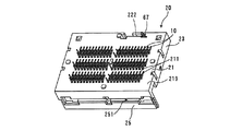
さらには、図7は、図1に組立状態を示す本実施形態のコネクタを構成する全部品を分解して示した分解斜視図である。 Further, FIG. 7 is an exploded perspective view showing all parts constituting the connector of the present embodiment shown in the assembled state in FIG. 1 in an exploded manner.
さらに図8は、図1のコネクタを上下逆さにして、そのコネクタの全部品を分解して示した分解斜視図である。 Further, FIG. 8 is an exploded perspective view showing the connector of FIG. 1 upside down and disassembling all components of the connector.
ここでは、図7,図8に示す分解斜視図を中心にし、必要に応じて図1〜図6を参照しながらこのコネクタ100の構成を説明する。
Here, the configuration of the
本実施形態のコネクタ100は、複数のコンタクト10と、ベースハウジング20と、スライダ30と、アッパハウジング40と、アウタシェル50とを備えている。
The
ベースハウジング20は、底板21を有する。この底板には、その底板21の表裏面に貫通した多数の長孔211が形成されている。これらの長孔211には、その底板21の底面側(図6に示されている底面219側)からコンタクト10が圧入される。図7,図8には、各長孔211に圧入されることにより配列された状態のコンタクト10が示されている。
The
これらのコンタクト10の、ベースハウジング20の底板21から底面219側に食み出た部分(図6参照)は、このコネクタ100が置かれる回路基板(図示せず)に接続される。
The portions of these
また、図7に示すように、底板21には、長孔211のほか、左右に溝212,213が形成されている。左側の溝212には、コイルバネ61が収容され、右側の溝213には、いわゆるハートカム溝が形成されたカム部材62およびコイルバネ63が収容される。カム部材62に形成されたハートカム溝にはカム棒69の一端が差し込まれる。このカム棒69の他端は、ベースハウジング20に支持される。
Further, as shown in FIG. 7, the
また、このベースハウジング20は、底板21を取り囲むように立設した後壁22、左右の側壁23,24、前壁25を有する。
The
前壁25には、相手コネクタの挿入部が挿入される挿入口251が設けられている。この挿入口251の直ぐ内側には、アッパハウジング40に支持された蓋部材64が配置されて、挿入口251が蓋部材64で塞がれる構造となっている(図1参照)。この蓋部材64は、相手コネクタの挿入部先端で外側から押されると内側上方に回動して挿入口251を開放し、相手コネクタが抜かれるとトーションバネ65の作用で挿入口251を塞ぐ構造となっている。
The
ベースハウジング20の底板21の上には、スライダ30が図4(B)に示すように配置される。このスライダ30には、カム板31と、そのカム板31の後端側において立設した立壁32とを有する。カム板31には、表裏に貫通してコンタクト10を図4(B)に示すように通過させる多数の長孔311と、カム部材62を通過させる長孔312が形成されている。このカム板31は、ベースハウジング20内で2本のコイルバネ61,63により、前壁25側に押された状態となる。コイルバネ61は、ベースハウジング20の溝212に収容されてスライダ30を直接に前壁25側に押す。もう1つのコイルバネ63は、ベースハウジング20の溝213に配置されて直接にカム部材62を押す。このカム部材62は、スライダ30の長孔312にも置かれている。このため、コイルバネ63に押されたカム部材62がスライダ30の長孔312の壁を押すことにより、スライダ30がカム部材62を介してベースハウジング20の前壁25側に押された状態となる。
A
ここで、本実施形態では、スライダ30が本発明にいう押当部材の一例であり、立壁32が本発明にいう当接部の一例に相当し、カム板31が本発明にいうカム部の一例に相当する。
Here, in this embodiment, the
さらに、スライダ30の上には、図4(A)に示すアッパハウジング40が配置され、さらにそのアッパハウジング40の上には図2(A)に示すアウタシェル50が被せられる。このアウタシェル50は金属製であって接地電位に保たれることにより、このコネクタ100のシールドの役割りを担っている。
Further, an
アッパハウジング40は、上板41と、前側においてその上板41から立設した前壁42とを有する。上板41は、ベースハウジング20の底板21との間にスライダ30が配置される空間を形成している。この上板41には、コンタクト10を通過させる多数の長孔411が形成され、さらに、スライダ30の立壁32を通過させる長孔412が形成されている。
The
また、前述のカム部材62には、突当部621が設けられており、アッパハウジング40の上板41には、そのカム部材62の突当部621を通過させる長孔413も形成されている。
The
また、このアッパハウジング40の前壁42には、ベースハウジング20の前壁25に形成された挿入口251から挿入されてきた相手コネクタの挿入部を受け入れる受入口421が形成されている。また、図5(A)に示すように、この前壁42の、受入口421の上部には、蓋部材64を回動自在に支持する支持部422が設けられている。蓋部材64は、その支持部422に、図4(A)に示すように支持され、内側上方に回動自在となっている。この蓋部材64は、トーションバネ65により、ベースハウジング20の挿入口251を塞ぐ向きに付勢されている。
In addition, the
相手コネクタの挿入部は、ベースハウジング20の、図1に示す挿入口251から挿入される。次に、挿入部は、アッパハウジング40に支持されている蓋部材64を押し上げてアッパハウジング40の受入口421から、図2(B)に示すように組立てられている状態の組立体の、アッパハウジング40の上に挿入される。挿入されてきた相手コネクタの挿入部の先端は、先ずはカム部材62の突当部621に突き当たってカム部材62をコイルバネ63のバネ付勢に抗して奥側にスライドさせる。カム部材62が奥に向かってスライドして突当部621がスライダ30の立壁32に並ぶと、相手コネクタの挿入部先端はカム部材62の突当部621とともにスライダ30の立壁32にも突き当たる。このため、挿入部先端は、カム部材62とスライダ30を一緒に、2本のコイルバネ61,63によるバネ付勢に抗して奥側にスライドさせる。すなわち、本実施形態のコネクタ100では、アッパハウジング40の上板41の上、すなわち、その上板41と、その上に被せられるアウターシェル50とに挟まれた空間が、本発明にいう、相手コネクタを受容する「挿入受部」の一例に相当する。
The mating connector insertion portion is inserted through the
ここで、コンタクト10の上端は、相手コネクタの挿入部の挿入前においては、アッパハウジング40の上板41に設けられた、コンタクト10を通過させる長孔411の内部に位置し、上板41の上面からは突出していない形状となっている(図2(B)参照。)。すなわちコンタクト10は、相手コネクタの挿入部の挿入前および挿入初期においては、相手コネクタの挿入部が挿入受部に挿入された場合の、その挿入部から離間して、その挿入部に対面する位置に配備されている。
Here, the upper end of the
また、相手コネクタの挿入部の、アッパハウジング40の上板41側を向いた面(本発明にいう「第1面」の一例に相当する)には、コンタクト10の配列に合致した配列の、多数の接続パッドが形成されている。
Further, on the surface of the mating connector insertion portion facing the
相手コネクタの挿入部が挿入受部、すなわちアッパハウジング40の上板41の上面側に挿入され、その挿入の最終の移動時にスライダ30の立壁32が相手コネクタの挿入部に押されてスライドする。その後にそのスライダ30のカム板31に設けられている長孔311の壁でコンタクト10を押して、そのコンタクト10をアッパハウジング40の上板41の長孔411から上に突出する向きに変形させる。その上板41の上面には相手コネクタの挿入部が挿入されており、その挿入部の下面(第1面)に形成されている接続パッドにコンタクト10が電気的に接続される。コンタクト10がスライダ30に押されて変形する様子については、後で説明する。
The insertion portion of the mating connector is inserted into the insertion receiving portion, that is, the upper surface side of the
相手コネクタの挿入部が奥まで挿入されて接続パッドとコンタクト10とが接続された状態になると、カム部材62のハートカム溝とカム棒69とが係合してカム部材62が奥側にスライドした状態のままロックされる。このカム部材62はスライダ30のカム板31の長孔312に入り込んでスライダ30を一緒に奥にスライドさせているため、カム部材62がロックされるとスライダ30も奥側にスライドした状態にとどまる。カム部材62の差込穴622にはロック部材66の差込片661が差し込まれており、そのロック部材66のロック部662が、挿入されている相手コネクタの挿入部の側面の凹部(図示せず)に係合し、相手コネクタをその挿入された状態にロックする。
When the insertion portion of the mating connector is inserted to the back and the connection pad and the
また、ベースハウジング20には、その後端側の溝222にスイッチ片67が支持されている。このスイッチ片67は、奥側にスライドしてきたスライダ30により端部671が押されて接触部672がアウタシェル50に接触して接地電位となる。これを回路基板側で検知することにより、このコネクタ100と相手コネクタとの嵌合が認識される。
Further, the
図3に示すように、アウタシェル50の内面には、金属製のバネ接片68が取り付けられている。相手コネクタの挿入部の、アウタシェル50側を向いた面には接地パッドが広がっている。バネ接片68は、挿入部が挿入受部(アッパハウジング40の上板41とアウタシェル50とで区画された空間)に挿入された挿入部の接地パッドに接続され、その接地パッドを接地電位に保持する役割を担っている。
As shown in FIG. 3, a metal
相手コネクタの挿入部が挿入受部に挿入されている状態においてその相手コネクタが挿入方向奥側に向けて再度押されると、カム部材62のハートカム溝とカム棒69との係止が外れる。このため、2本のコイルバネ61,63の付勢力により、スライダ30が前方にスライドする。また、カム部材62も前方にスライドすることにより、相手コネクタの挿入部をロックしていたロック部材62による挿入部のロックも外れる。このようにして、相手コネクタがこのコネクタ100から押し出される。
If the mating connector is pushed again toward the back in the insertion direction in a state where the mating connector insertion portion is inserted into the insertion receiving portion, the engagement between the heart cam groove of the
図9は、図1〜図8に示す本実施形態のコネクタに相手コネクタの挿入部が挿入されてきたときの、最終段階の動作を示した断面図である。 FIG. 9 is a cross-sectional view showing the operation at the final stage when the insertion portion of the mating connector has been inserted into the connector of the present embodiment shown in FIGS.
図9(A)は、相手コネクタ700の板形状の挿入部710が最終位置よりも少し前の位置まで挿入された状態を示した図、図9(B)は、挿入部710が最終位置まで挿入された状態を示した図である。
9A shows a state in which the plate-shaped
相手コネクタ700の挿入部710は板形状を有し、その挿入部710の第1面(コンタクト10側を向いた面)には、コンタクト10に対応する接続パッド711が形成されている。また、その挿入部710の第2面(アウタシェル50側を向いた面)には、接地パッド712が形成されている。
The
本実施形態のコネクタ100は、これまで説明してきた通り、回路基板(図示せず)に接続される下側から順に、ベースハウジング20、スライダ30、アッパハウジング40が積み重ねられている。そして、アッパハウジング40の上に相手コネクタ700の挿入部710を受容する挿入受部が形成されてアウタシェル50が被せられている。
As described above, the
コンタクト10は、ベースハウジング20の長孔211に圧入されて保持されている。このコンタクト10は、スライダ30の長孔311を通り、さらにアッパハウジング40の長孔411に入り込んでいる。ただし、図9(A)に示すように相手コンタクト700の挿入部710の挿入前および挿入の初期段階においては、コンタクト10の上端はアッパハウジング40の長孔411の内側にとどまっている。すなわち、このコンタクト10は、挿入前および挿入の初期段階においては、相手コンタクト700の挿入部710が挿入受部に挿入された場合の、その挿入部710に対面する位置であって、その挿入部710から離間した位置にある。スライダ30のカム板31の、長孔311それぞれを構成している、挿入方向後側(図9の左側)の壁には、上向き斜めのカム面313が形成されている。スライダ30が相手コネクタ700の挿入部710の先端に押されて奥側にスライドすると、図9(A)に示すようにそのカム面313がコンタクト10の途中部分に当たる。この結果、相手コネクタ700の挿入部710がさらに奥に挿入される過程で、そのカム面313でコンタクト10の途中部分よりも上の部分が持ち上げられるように弾性変形し、図9(B)に示す状態となる。このときには、各コンタクト10は、相手コネクタ700の挿入部710の第1面に形成されている、対応する各接続パッド711に押し当てられて電気的に導通する。また、挿入部710の第2面に形成されている接地パッド712には、アウタシェル50に取り付けられているバネ接片68が接触した状態となる。
The
このように、本実施形態のコネクタ100によれば、相手コネクタ700の挿入部710の挿入受部への挿入の最終段階でコンタクト10が接続パッド711に押し当てられる。このため、挿入動作最終段階までは挿入部710はコンタクト10の干渉を受けずに低挿入力で挿入される。またスライダ30は、相手コネクタ700の挿入部710から力を受けてコンタクト10を接続パッド711に押し当てるため、挿入の操作だけで嵌合が完結する。
As described above, according to the
さらに、本実施形態のコネクタ100は、相手コネクタ700の挿入部710の第1面に挿入方向に複数の接続パッドが配列され、それに対応して本実施形態のコネクタ100は挿入方向に並ぶ複数のコンタクト10を備えている構成である。しかし、接続パッド711を備えた挿入部710にコンタクト10が接触するのは挿入の最終段階である。このため、挿入の途中段階で接続パッド711にその接続パッド711には対応していないコンタクト10が接触して誤動作を生じる危険はない。また、挿入方向前方の接続パッド711ほどコンタクト10と何度も摺擦してしまい短寿命化するようなおそれもない。
Furthermore, in the
ただし、回路構成等の工夫で、挿入の途中段階で対応していない接続パッドとコンタクトが接触しても誤動作を生じないようになっている場合は、コンタクト10がアッパハウジング40の上板41から僅かに突出していて相手コネクタの挿入部がコンタクトに軽く接触しながら挿入される構造であってもよい。
However, if the circuit configuration or the like prevents the malfunction even if the contact between the contact pad and the contact that is not supported in the middle of the insertion occurs, the
10 コンタクト
20 ベースハウジング
30 スライダ
31 カム板
32 立壁
40 アッパハウジング
50 アウタシェル
61,63 コイルバネ
62 カム部材
64 蓋部材
65 トーションバネ
66 ロック部材
67 スイッチ片
68 バネ片
69 カム棒
100 コネクタ
211,311,312,411,412,413 長孔
212,213 溝
251 挿入口
421 受入口
422 支持部
621 突当部
700 相手コネクタ
710 挿入部
711 接続パッド
712 接地パッド
10
Claims (1)
前記挿入部が前記挿入受部に挿入された場合に前記下面に対面すると共に、前記挿入部の前記挿入受部への挿入の初期段階において前記下面から下方に離間した位置であって、相手コネクタの挿入方向に少なくとも3列に亘り互いに同じ形状を有し互いに同じ向きに配列された、前記接続パッドに対応するコンタクトと、
前記挿入部の前記挿入受部への挿入の最終の移動時に該挿入部から力を受けて前記コンタクトを前記接続パッドに押し当てる押当部材とを備え、
前記押当部材が、前記挿入受部に挿入されてきた前記挿入部の当接を受ける当接部を有し、該挿入部により該当接部が押されて該挿入部とともに挿入方向奥側に移動するものであって、当該押当部材がさらに、該移動の過程で前記コンタクトを前記挿入受部に挿入されてきた前記挿入部の前記下面に向けて押すことにより、該コンタクトを弾性変形させて前記接続パッドに押し当てるカム部を有する部材であることを特徴とするコネクタ。 A housing having an insertion receiving portion for receiving the insertion portion of the mating connector having a plate-like insertion portion having a connection pad formed on the lower surface ;
Wherein the insertion portion is facing said lower surface when it is inserted into the insertion receiving portion, a position spaced from the lower surface downwardly in the early stages of insertion into the insertion receiving portion of the insertion portion, the mating connector Contacts corresponding to the connection pads, which have the same shape and are arranged in the same direction over at least three rows in the insertion direction ;
A pressing member that receives a force from the insertion portion and presses the contact against the connection pad during the final movement of the insertion portion into the insertion receiving portion ;
The pressing member has a contact portion that receives the contact of the insertion portion that has been inserted into the insertion receiving portion, and the corresponding contact portion is pushed by the insertion portion to the back in the insertion direction together with the insertion portion. The pushing member further elastically deforms the contact by pushing the contact toward the lower surface of the insertion portion inserted into the insertion receiving portion in the course of the movement. A connector having a cam portion pressed against the connection pad .
Priority Applications (5)
| Application Number | Priority Date | Filing Date | Title |
|---|---|---|---|
| JP2012246246A JP6000811B2 (en) | 2012-11-08 | 2012-11-08 | connector |
| KR1020130134132A KR102041924B1 (en) | 2012-11-08 | 2013-11-06 | Connector |
| EP13191896.3A EP2731199B1 (en) | 2012-11-08 | 2013-11-07 | Connector |
| CN201310550013.1A CN103811935B (en) | 2012-11-08 | 2013-11-08 | Connector |
| US14/075,221 US9780473B2 (en) | 2012-11-08 | 2013-11-08 | Mating connector using slider to deform contacts |
Applications Claiming Priority (1)
| Application Number | Priority Date | Filing Date | Title |
|---|---|---|---|
| JP2012246246A JP6000811B2 (en) | 2012-11-08 | 2012-11-08 | connector |
Publications (3)
| Publication Number | Publication Date |
|---|---|
| JP2014096249A JP2014096249A (en) | 2014-05-22 |
| JP2014096249A5 JP2014096249A5 (en) | 2015-11-19 |
| JP6000811B2 true JP6000811B2 (en) | 2016-10-05 |
Family
ID=49518860
Family Applications (1)
| Application Number | Title | Priority Date | Filing Date |
|---|---|---|---|
| JP2012246246A Active JP6000811B2 (en) | 2012-11-08 | 2012-11-08 | connector |
Country Status (5)
| Country | Link |
|---|---|
| US (1) | US9780473B2 (en) |
| EP (1) | EP2731199B1 (en) |
| JP (1) | JP6000811B2 (en) |
| KR (1) | KR102041924B1 (en) |
| CN (1) | CN103811935B (en) |
Families Citing this family (8)
| Publication number | Priority date | Publication date | Assignee | Title |
|---|---|---|---|---|
| JP6215125B2 (en) * | 2014-04-21 | 2017-10-18 | 日本航空電子工業株式会社 | connector |
| JP6524465B2 (en) * | 2015-04-28 | 2019-06-05 | タイコエレクトロニクスジャパン合同会社 | connector |
| JP1545402S (en) * | 2015-04-28 | 2016-03-14 | ||
| US11112448B2 (en) * | 2017-04-12 | 2021-09-07 | Kemitec Inc | Low insertion force connector assembly and semiconductor component test apparatus |
| US10916903B2 (en) | 2018-02-04 | 2021-02-09 | Creganna Unlimited Company | System having a cable assembly and plug and receptacle connectors |
| US10418734B1 (en) | 2018-07-26 | 2019-09-17 | Te Connectivity Corporation | Contact assembly for a straddle mount connector |
| US10559920B1 (en) | 2018-08-07 | 2020-02-11 | Te Connectivity Corporation | Card edge connector having improved mating interface |
| JP7316192B2 (en) * | 2019-10-29 | 2023-07-27 | タイコエレクトロニクスジャパン合同会社 | socket |
Family Cites Families (14)
| Publication number | Priority date | Publication date | Assignee | Title |
|---|---|---|---|---|
| JPH054705Y2 (en) * | 1987-10-06 | 1993-02-05 | ||
| US4936790A (en) * | 1989-04-28 | 1990-06-26 | Apple Computer, Inc. | Low insertion force connector |
| DE4010398A1 (en) * | 1990-03-31 | 1991-10-10 | Stocko Metallwarenfab Henkels | DEVICE FOR ELECTRICALLY CONTACTING AN IC MEMORY CARD WITH AN ELECTRONIC DEVICE |
| DE4336192A1 (en) * | 1993-10-23 | 1995-05-04 | Thomas & Betts Gmbh | Reader for chip cards |
| JP2985760B2 (en) * | 1996-03-14 | 1999-12-06 | 株式会社田村電機製作所 | IC card connector |
| US5679018A (en) | 1996-04-17 | 1997-10-21 | Molex Incorporated | Circuit card connector utilizing flexible film circuitry |
| US5750973A (en) * | 1996-10-31 | 1998-05-12 | The Whitaker Corporation | Card reader |
| JP2001203048A (en) * | 2000-01-20 | 2001-07-27 | Fujitsu Takamisawa Component Ltd | Connector and electronic components |
| JP3710705B2 (en) | 2000-11-30 | 2005-10-26 | タイコエレクトロニクスアンプ株式会社 | Low insertion force connector |
| US20020070274A1 (en) * | 2000-12-11 | 2002-06-13 | Tien-Tsai Lee | IC card reading connector |
| US6796842B1 (en) * | 2003-10-08 | 2004-09-28 | Ming-Te Wang | Electronic card connector |
| US7044797B1 (en) * | 2005-01-26 | 2006-05-16 | Taisol Electronics Co., Ltd. | Memory card connector |
| JP4973485B2 (en) * | 2007-12-21 | 2012-07-11 | 日本電気株式会社 | connector |
| TWM382611U (en) * | 2009-07-23 | 2010-06-11 | Hon Hai Prec Ind Co Ltd | Electrical card connector |
-
2012
- 2012-11-08 JP JP2012246246A patent/JP6000811B2/en active Active
-
2013
- 2013-11-06 KR KR1020130134132A patent/KR102041924B1/en active IP Right Grant
- 2013-11-07 EP EP13191896.3A patent/EP2731199B1/en active Active
- 2013-11-08 US US14/075,221 patent/US9780473B2/en active Active
- 2013-11-08 CN CN201310550013.1A patent/CN103811935B/en active Active
Also Published As
| Publication number | Publication date |
|---|---|
| CN103811935A (en) | 2014-05-21 |
| KR20140059736A (en) | 2014-05-16 |
| CN103811935B (en) | 2017-09-22 |
| KR102041924B1 (en) | 2019-11-07 |
| EP2731199A1 (en) | 2014-05-14 |
| US20140127922A1 (en) | 2014-05-08 |
| US9780473B2 (en) | 2017-10-03 |
| EP2731199B1 (en) | 2019-09-25 |
| JP2014096249A (en) | 2014-05-22 |
Similar Documents
| Publication | Publication Date | Title |
|---|---|---|
| JP6000811B2 (en) | connector | |
| US7785146B2 (en) | Locking device for connector elements and a connector provided with said device | |
| TW201334310A (en) | Connector | |
| JP2016134358A (en) | Card tray and card connector | |
| JP2016207598A (en) | connector | |
| US20130059454A1 (en) | Cover structure | |
| JP2014096249A5 (en) | ||
| JP2012234773A (en) | Connector terminal and card edge type connector containing connector terminal | |
| JP4798277B2 (en) | connector | |
| JP2016207599A (en) | connector | |
| JP6471048B2 (en) | Card connector | |
| JP5862387B2 (en) | connector | |
| JP2009301987A (en) | Connection structure of plug and receptacle | |
| JP2007066586A (en) | Connector for memory card | |
| US20150249306A1 (en) | Electrical card connector with eject mechanism | |
| US10581197B2 (en) | Plug connector assembly having improved locking structure | |
| US20100099284A1 (en) | Card connector | |
| JP5660376B2 (en) | Connector with lever | |
| KR20150002604U (en) | Connector | |
| JP5411803B2 (en) | Connector for optical module | |
| JP4916845B2 (en) | Connector assembly and connector | |
| JP3185159U (en) | USB connector combination structure | |
| JP3185158U (en) | USB connector combination structure | |
| US7275944B1 (en) | Card connector capable of detecting insertion of card | |
| KR101489491B1 (en) | Release locking board to board connector |
Legal Events
| Date | Code | Title | Description |
|---|---|---|---|
| A521 | Request for written amendment filed |
Free format text: JAPANESE INTERMEDIATE CODE: A523 Effective date: 20151002 |
|
| A621 | Written request for application examination |
Free format text: JAPANESE INTERMEDIATE CODE: A621 Effective date: 20151002 |
|
| A977 | Report on retrieval |
Free format text: JAPANESE INTERMEDIATE CODE: A971007 Effective date: 20160623 |
|
| A131 | Notification of reasons for refusal |
Free format text: JAPANESE INTERMEDIATE CODE: A131 Effective date: 20160628 |
|
| A521 | Request for written amendment filed |
Free format text: JAPANESE INTERMEDIATE CODE: A523 Effective date: 20160802 |
|
| TRDD | Decision of grant or rejection written | ||
| A01 | Written decision to grant a patent or to grant a registration (utility model) |
Free format text: JAPANESE INTERMEDIATE CODE: A01 Effective date: 20160830 |
|
| A61 | First payment of annual fees (during grant procedure) |
Free format text: JAPANESE INTERMEDIATE CODE: A61 Effective date: 20160831 |
|
| R150 | Certificate of patent or registration of utility model |
Ref document number: 6000811 Country of ref document: JP Free format text: JAPANESE INTERMEDIATE CODE: R150 |
|
| R250 | Receipt of annual fees |
Free format text: JAPANESE INTERMEDIATE CODE: R250 |
|
| R250 | Receipt of annual fees |
Free format text: JAPANESE INTERMEDIATE CODE: R250 |
|
| R250 | Receipt of annual fees |
Free format text: JAPANESE INTERMEDIATE CODE: R250 |
|
| R250 | Receipt of annual fees |
Free format text: JAPANESE INTERMEDIATE CODE: R250 |
|
| R250 | Receipt of annual fees |
Free format text: JAPANESE INTERMEDIATE CODE: R250 |