JP6000763B2 - Image processing apparatus and image processing method - Google Patents
Image processing apparatus and image processing method Download PDFInfo
- Publication number
- JP6000763B2 JP6000763B2 JP2012192292A JP2012192292A JP6000763B2 JP 6000763 B2 JP6000763 B2 JP 6000763B2 JP 2012192292 A JP2012192292 A JP 2012192292A JP 2012192292 A JP2012192292 A JP 2012192292A JP 6000763 B2 JP6000763 B2 JP 6000763B2
- Authority
- JP
- Japan
- Prior art keywords
- frame
- picture identifier
- slice type
- bit length
- idr
- Prior art date
- Legal status (The legal status is an assumption and is not a legal conclusion. Google has not performed a legal analysis and makes no representation as to the accuracy of the status listed.)
- Expired - Fee Related
Links
Images


Classifications
-
- H—ELECTRICITY
- H04—ELECTRIC COMMUNICATION TECHNIQUE
- H04N—PICTORIAL COMMUNICATION, e.g. TELEVISION
- H04N19/00—Methods or arrangements for coding, decoding, compressing or decompressing digital video signals
- H04N19/46—Embedding additional information in the video signal during the compression process
-
- H—ELECTRICITY
- H04—ELECTRIC COMMUNICATION TECHNIQUE
- H04N—PICTORIAL COMMUNICATION, e.g. TELEVISION
- H04N19/00—Methods or arrangements for coding, decoding, compressing or decompressing digital video signals
- H04N19/10—Methods or arrangements for coding, decoding, compressing or decompressing digital video signals using adaptive coding
- H04N19/169—Methods or arrangements for coding, decoding, compressing or decompressing digital video signals using adaptive coding characterised by the coding unit, i.e. the structural portion or semantic portion of the video signal being the object or the subject of the adaptive coding
- H04N19/17—Methods or arrangements for coding, decoding, compressing or decompressing digital video signals using adaptive coding characterised by the coding unit, i.e. the structural portion or semantic portion of the video signal being the object or the subject of the adaptive coding the unit being an image region, e.g. an object
- H04N19/174—Methods or arrangements for coding, decoding, compressing or decompressing digital video signals using adaptive coding characterised by the coding unit, i.e. the structural portion or semantic portion of the video signal being the object or the subject of the adaptive coding the unit being an image region, e.g. an object the region being a slice, e.g. a line of blocks or a group of blocks
-
- H—ELECTRICITY
- H04—ELECTRIC COMMUNICATION TECHNIQUE
- H04N—PICTORIAL COMMUNICATION, e.g. TELEVISION
- H04N19/00—Methods or arrangements for coding, decoding, compressing or decompressing digital video signals
- H04N19/10—Methods or arrangements for coding, decoding, compressing or decompressing digital video signals using adaptive coding
- H04N19/102—Methods or arrangements for coding, decoding, compressing or decompressing digital video signals using adaptive coding characterised by the element, parameter or selection affected or controlled by the adaptive coding
- H04N19/103—Selection of coding mode or of prediction mode
- H04N19/105—Selection of the reference unit for prediction within a chosen coding or prediction mode, e.g. adaptive choice of position and number of pixels used for prediction
-
- H—ELECTRICITY
- H04—ELECTRIC COMMUNICATION TECHNIQUE
- H04N—PICTORIAL COMMUNICATION, e.g. TELEVISION
- H04N19/00—Methods or arrangements for coding, decoding, compressing or decompressing digital video signals
- H04N19/10—Methods or arrangements for coding, decoding, compressing or decompressing digital video signals using adaptive coding
- H04N19/134—Methods or arrangements for coding, decoding, compressing or decompressing digital video signals using adaptive coding characterised by the element, parameter or criterion affecting or controlling the adaptive coding
- H04N19/146—Data rate or code amount at the encoder output
-
- H—ELECTRICITY
- H04—ELECTRIC COMMUNICATION TECHNIQUE
- H04N—PICTORIAL COMMUNICATION, e.g. TELEVISION
- H04N19/00—Methods or arrangements for coding, decoding, compressing or decompressing digital video signals
- H04N19/10—Methods or arrangements for coding, decoding, compressing or decompressing digital video signals using adaptive coding
- H04N19/169—Methods or arrangements for coding, decoding, compressing or decompressing digital video signals using adaptive coding characterised by the coding unit, i.e. the structural portion or semantic portion of the video signal being the object or the subject of the adaptive coding
- H04N19/17—Methods or arrangements for coding, decoding, compressing or decompressing digital video signals using adaptive coding characterised by the coding unit, i.e. the structural portion or semantic portion of the video signal being the object or the subject of the adaptive coding the unit being an image region, e.g. an object
- H04N19/172—Methods or arrangements for coding, decoding, compressing or decompressing digital video signals using adaptive coding characterised by the coding unit, i.e. the structural portion or semantic portion of the video signal being the object or the subject of the adaptive coding the unit being an image region, e.g. an object the region being a picture, frame or field
-
- H—ELECTRICITY
- H04—ELECTRIC COMMUNICATION TECHNIQUE
- H04N—PICTORIAL COMMUNICATION, e.g. TELEVISION
- H04N19/00—Methods or arrangements for coding, decoding, compressing or decompressing digital video signals
- H04N19/90—Methods or arrangements for coding, decoding, compressing or decompressing digital video signals using coding techniques not provided for in groups H04N19/10-H04N19/85, e.g. fractals
- H04N19/91—Entropy coding, e.g. variable length coding [VLC] or arithmetic coding
-
- H—ELECTRICITY
- H04—ELECTRIC COMMUNICATION TECHNIQUE
- H04N—PICTORIAL COMMUNICATION, e.g. TELEVISION
- H04N19/00—Methods or arrangements for coding, decoding, compressing or decompressing digital video signals
- H04N19/10—Methods or arrangements for coding, decoding, compressing or decompressing digital video signals using adaptive coding
- H04N19/102—Methods or arrangements for coding, decoding, compressing or decompressing digital video signals using adaptive coding characterised by the element, parameter or selection affected or controlled by the adaptive coding
- H04N19/115—Selection of the code volume for a coding unit prior to coding
Description
本発明は、画像処理装置及び画像処理方法に関するものである。 The present invention relates to an image processing apparatus and an image processing method .
近年、撮影後の編集の容易さから画面内符号化(イントラ符号化)を利用した動画を撮影できる機種が増えてきている。画面内符号化された画像は、画面間符号化(インター符号化)と異なり、いわゆる参照画像が必要ない。符号化された1枚の画像データがあれば復号することが可能で、動画像から静止画像を切り出す、といった編集作業が容易である。 In recent years, an increasing number of models can shoot moving images using intra-screen coding (intra coding) because of easy editing after shooting. Unlike the inter-screen coding (inter-coding), the so-called reference image is not necessary for the intra-coded image. If there is one piece of encoded image data, it can be decoded, and editing such as cutting out a still image from a moving image is easy.
ただし、便利な反面、画面間符号化を使用する場合に比べて、符号化効率が悪くなってしまうという欠点もある。画面間符号化を使用して動画像を符号化するMPEGに比べて、画面内符号化のみのMotionJPEGの符号量は一般的に多くなる。そのため、編集作業の手間はあるものの、動画像の符号化にはMPEGが用いられることが多かった。 However, it is convenient, but there is a disadvantage that the encoding efficiency is deteriorated as compared with the case of using inter-frame encoding. Compared to MPEG, which encodes a moving image using inter-screen coding, the amount of code of Motion JPEG with only intra-screen coding is generally large. For this reason, MPEG is often used for encoding moving images, although there is a trouble of editing work.
その一方でH.264といったJPEGやMPEGよりも効率のよい画像符号化が可能な方式が普及することにより、再び画面内符号化の動画が注目されている。H.264には画面内予測や予測ブロックサイズを適応的に変えることができる等、画面内符号化に関してだけでも効率を上げるツールがたくさん採用されている。 On the other hand, with the popularization of H.264, which enables more efficient image coding than JPEG and MPEG, moving pictures with intra-screen coding are attracting attention again. H.264 employs a number of tools that improve efficiency only with respect to intra-frame coding, such as the ability to adaptively change intra-frame prediction and prediction block size.
H.264においては、IDR(Instantaneous Decoding Refresh)と呼ばれる特殊な画面内符号化ピクチャ(以下、IDRピクチャ)が用いられる。IDRピクチャが挿入されると、ストリームを復号するために必要な全ての状態がリセットされる(H.264のストリームの先頭は、必ずIDRでなければならない)。逆にIDRピクチャに関してその他の制約はなく、以降、どのタイミングでIDRピクチャが挿入されてもよい。即ち、全てのフレームがIDRピクチャであってもよいし、先頭以外、一切IDRピクチャがなくてもよい。 In H.264, a special intra-picture coded picture (hereinafter referred to as IDR picture) called IDR (Instantaneous Decoding Refresh) is used. When an IDR picture is inserted, all the states necessary to decode the stream are reset (the head of the H.264 stream must always be IDR). Conversely, there are no other restrictions on the IDR picture, and the IDR picture may be inserted at any timing thereafter. That is, all the frames may be IDR pictures, or there may be no IDR pictures other than the head.
画面内符号化されたフレームのピクチャタイプには、IDRピクチャ以外に通常のIピクチャもある。IピクチャはMPEGに採用されているIピクチャと同じで、俗に言うGOPの先頭という意味で捉えることができる。ストリームの画像データの部分において、IDRピクチャとIピクチャは、符号化効率が変わるなどの差はない。 In addition to the IDR picture, there is a normal I picture as the picture type of the intra-coded frame. The I picture is the same as the I picture adopted in MPEG, and can be understood as the head of GOP. In the image data portion of the stream, there is no difference between the IDR picture and the I picture in that the coding efficiency changes.
よって、画面内符号化のみを用いた画像符号化方式(以下、ALL−Iピクチャ)で動画像を作成する場合、全てIDRピクチャにするか、Iピクチャも混ぜる(または先頭以外全てIピクチャなど)かの2通りの方法がある。しかし、例えばIDRピクチャを含む動画の途中のストリームを削除して、削除した前後のストリームを接続する、といった場合に別の問題が発生する。 Therefore, when creating a moving picture by an image coding method using only intra-picture coding (hereinafter referred to as ALL-I picture), all IDR pictures are mixed or I pictures are mixed (or all I pictures other than the head). There are two ways. However, another problem occurs when, for example, a stream in the middle of a moving image including an IDR picture is deleted and the streams before and after the deletion are connected.
IDRピクチャには各ピクチャにピクチャ識別子(idr_pic_id)というパラメータがあり、ヘッダ内に書き込む必要がある。ピクチャ識別子は、H.264ではゴロム符号化という可変長符号化方式を用いて、IDRピクチャのピクチャ画像と共に符号化されている。 An IDR picture has a parameter called a picture identifier (idr_pic_id) in each picture and needs to be written in the header. The picture identifier is H.264. In H.264, encoding is performed together with a picture image of an IDR picture by using a variable length encoding method called Golomb encoding.
図8の表を参照して、上記ピクチャ識別子を可変長符号化している手法の例としてゴロム符号化について説明を行う。図8の表の左側の列がゴロム符号(二進数)、右側の列が表現できるデータ値(十進数)の範囲である。図8の表のゴロム符号の1の部分はセパレータ、このセパレータを中心に左側の0がプリフィックス、右側がサフィックスと呼ばれている。サフィックスは図8の表ではxで表現されていて、xは0,1いずれかの値が入るという意味である。プリフィックスの0の数はサフィックスのビット長を表わしていて、セパレータを中心に、左右のビット長が同じになる。
With reference to the table of FIG. 8, Golomb coding will be described as an example of a technique for variable-length coding the picture identifier. The left column of the table of FIG. 8 is the Golomb code (binary number), and the right column is the range of data values (decimal number) that can be expressed. The 1 part of the Golomb code in the table of FIG. 8 is called a separator, and the
例えば、プリフィックスの0の数が2であった場合、サフィックスのビット長も2である。 For example, if the number of 0s in the prefix is 2, the bit length of the suffix is also 2.
図8の表でみると、上から3行目にあたり、表現できる値は3から6の4通りである。具体的にいうと、以下となる。
ゴロム符号:00100 = データ値:3
ゴロム符号:00101 = データ値:4
ゴロム符号:00110 = データ値:5
ゴロム符号:00111 = データ値:6
データ値0のときだけ例外で、プリフィックスとサフィックスが存在しない。このように数値の変換を可変長とすることで、符号化効率が向上する。
In the table of FIG. 8, the values that can be expressed in the third line from the top are 4 from 3 to 6. Specifically, it is as follows.
Golomb code: 00100 = data value: 3
Golomb code: 00101 = data value: 4
Golomb code: 00110 = data value: 5
Golomb code: 00111 = data value: 6
There is an exception only when the data value is 0, and there is no prefix or suffix. Thus, encoding efficiency improves by making numerical conversion variable length.
ピクチャ識別子はH.264勧告によると、0から65535までの任意の値をとってよいが、IDRピクチャが隣り合う場合、同じピクチャ識別子が続いてはいけないという規定がある。隣接したIDRピクチャで、同じピクチャ識別子が続けて付与されない限りは、同じピクチャ識別子が一つの動画の中で使用されても構わない。 The picture identifier is H.264. According to the H.264 recommendation, any value from 0 to 65535 may be taken. However, when IDR pictures are adjacent to each other, there is a rule that the same picture identifier should not follow. As long as the same picture identifier is not continuously given to adjacent IDR pictures, the same picture identifier may be used in one moving image.
しかしながら編集作業が行われた場合、編集後に同じピクチャ識別子が連続してしまう可能性がある。編集後に同じピクチャ識別子が連続する場合、どちらかのピクチャ識別子を修正すればよいのだが、このピクチャ識別子は前述の通り可変長符号化(ゴロム符号化)されており、その値だけの編集ができない場合がある。 However, when editing work is performed, the same picture identifier may continue after editing. If the same picture identifier continues after editing, one of the picture identifiers may be corrected, but this picture identifier is variable-length encoded (Golomb encoded) as described above, and only that value cannot be edited. There is a case.
例えば、2つの連続するIDRピクチャのピクチャ識別子が2つとも0という値だった場合、ゴロム符号は1ビットの1という値で表現されている。同じピクチャ識別子が連続してはいけない、という規定から、どちらかのピクチャ識別子を変更しなければならないが、ゴロム符号化されているビットは1以外とることができない。 For example, when the picture identifiers of two consecutive IDR pictures are both 0, the Golomb code is represented by 1 value of 1 bit. One of the picture identifiers must be changed based on the rule that the same picture identifier must not be consecutive, but the Golomb-encoded bits cannot be other than 1.
また、2つの連続するIDRピクチャのピクチャ識別子が1でさらにその前後のピクチャ識別子が2だった場合も問題が生じる。ピクチャ識別子が1の場合のゴロム符号は、図8の表より"010"である。このビット長で表現できる1以外の数は、ゴロム符号"011"で表される2という値である。ピクチャ識別子が重なったIDRピクチャの一方を1以外の数字で置き換えなければならないが、この場合は1以外の値は2しか選択できない。しかしながら、2と変更すると、さらにその隣のIDRピクチャのピクチャ識別子と重なり、さらにそこで修整しなければならなくなる。 A problem also arises when the picture identifiers of two consecutive IDR pictures are 1 and the preceding and subsequent picture identifiers are 2. The Golomb code when the picture identifier is 1 is “010” from the table of FIG. The number other than 1 that can be expressed by this bit length is a value of 2 represented by Golomb code “011”. One of IDR pictures with overlapping picture identifiers must be replaced with a number other than 1, but in this case, only 2 can be selected for a value other than 1. However, if it is changed to 2, it overlaps with the picture identifier of the IDR picture next to it and must be further corrected there.
このように多数のIDRピクチャのピクチャ識別子を検索し、修整する必要が出てくる。場合によっては、重複を避けることが不可能な状況もありうる。このような場合は、再符号化するか、編集する場所を所望の位置から変える必要がある。 In this way, it is necessary to search and correct the picture identifiers of a large number of IDR pictures. In some cases, it may be impossible to avoid duplication. In such a case, it is necessary to re-encode or change the editing location from a desired position.
上記の問題を解決する手法として、ピクチャ識別子のみの編集ができない場合は、パディングビット等を削除してピクチャ識別子へのビット長の割り当てを増やす方法が提案されている(特許文献1)。 As a technique for solving the above-described problem, there has been proposed a method of deleting the padding bits or the like and increasing the bit length allocation to the picture identifier when editing only the picture identifier is not possible (Patent Document 1).
図9を用いて特許文献1にて提案されている実施例を説明する。ピクチャ識別子編集前のIDRピクチャは、
ヘッダ内のピクチャ識別子901(idr_pic_id)
ストリームデータのビット長を整えるために挿入されるパディングビット902(cabac_alignment_one_bit)
データの最後に挿入されるパディングビット905(trailing_zero_8bits)
を含む。
An embodiment proposed in
Picture identifier 901 (idr_pic_id) in the header
Padding bits 902 (cabac_alignment_one_bit) inserted to adjust the bit length of stream data
Padding bits 905 (trailing_zero_8 bits) inserted at the end of the data
including.
また、ピクチャ識別子編集後のピクチャは、
ピクチャ識別子901を変更可能なようにNビット拡張したピクチャ識別子903
パディングビット902からNビット削減したパディングビット904(cabac_alignment_one_bit)
ビット長を整えるためにデータの最後に挿入されるパディングビット906(trailing_zero_8bits)
を含む。
The picture after editing the picture identifier is
Padding bit 904 (cabac_alignment_one_bit) reduced by N bits from padding bit 902
Padding bits 906 (trailing_zero_8 bits) inserted at the end of the data to adjust the bit length
including.
ここではピクチャ識別子のみの編集ができない場合、変更できるゴロム符号になるように、ピクチャ識別子901のビット長をNビット増やして、Nビット拡張したピクチャ識別子903としている。しかし、そのままではピクチャ全体のビット長がNビット増加してしまい、H.264ストリームとして成立しなくなる可能性がある。そこでビット量を調整するため、cabac_alignment_one_bit902から増加したNビット分削減し、904とすることで、全体のビット量の増加が抑えられる。しかし、このcabac_alignment_one_bit902は、画像依存のデータであり、削減させたいNビット分の余裕がない可能性がある。その場合は、ストリームデータの最後についているtrailing_zero_8bits905から増加分を削減して、906にする。また、trailing_zero_8bitsも画像依存なので、存在しない場合がある。そのときは、次のスライスデータでつじつまを合わせる、としている。このような方法では、データ先頭にピクチャ識別子を編集するためのビット長を調整できるパラメータが存在する場合は比較的容易に編集できるが、存在しない場合はストリームを解析してパディングビットを調整しなければならないため処理が複雑化するおそれがある。
Here, when only the picture identifier cannot be edited, the bit length of the
そこで、本発明の目的は、動画像の編集の際に、編集後の動画像においてピクチャ識別子の連続を防止するためのピクチャ識別子の変更をより簡易とし、編集処理時の負担を軽減することを可能とする。 Accordingly, an object of the present invention is to make it easier to change picture identifiers to prevent continuation of picture identifiers in a edited moving image when editing a moving image, and to reduce the burden during editing processing. Make it possible.
上記目的を達成するために、本発明は、
第1の動画像と第2の動画像とを結合する処理を行う装置であって、
前記第1の動画像と前記第2の動画像の結合点の前後に隣接する第1のフレーム及び第2のフレームのピクチャ識別子とスライスタイプとを取得する取得手段と、
前記取得手段により取得された前記第1のフレームのピクチャ識別子と前記第2のフレームのピクチャ識別子とが一致するか否かを判定し、一致する場合に、前記第2のフレームのピクチャ識別子を、前記第1のフレームのピクチャ識別子と異なる値に変更する変更手段とを備え、
前記変更手段は、前記第2のフレームのスライスタイプが第1のスライスタイプと一致する場合、前記第2のフレームのスライスタイプを前記第1のスライスタイプよりもビット長が短い第2のスライスタイプへ変更する処理を行うとともに、前記第2のフレームのピクチャ識別子を、前記一致するピクチャ識別子よりも長いビット長に変更する処理を行うことを特徴とする。
In order to achieve the above object, the present invention provides:
An apparatus for performing processing for combining a first moving image and a second moving image,
Obtaining means for obtaining a picture identifier and a slice type of the first frame and the second frame adjacent to each other before and after a connection point between the first moving image and the second moving image;
It is determined whether or not the picture identifier of the first frame and the picture identifier of the second frame acquired by the acquisition unit match, and if they match, the picture identifier of the second frame is Changing means for changing to a value different from the picture identifier of the first frame,
When the slice type of the second frame matches the first slice type, the changing unit changes the slice type of the second frame to a second slice type having a bit length shorter than that of the first slice type. And a process of changing the picture identifier of the second frame to a bit length longer than the matching picture identifier .
本発明によれば、単一のIDRピクチャのヘッダ内のデータを変更することにより、編集後の動画像においてピクチャ識別子の連続を防止するためのピクチャ識別子の変更をより簡易とし、編集処理時の負担を軽減することが可能となる。 According to the present invention, changing the data in the header of a single IDR picture makes it easier to change the picture identifier for preventing the continuation of the picture identifier in the edited moving image. The burden can be reduced.
以下に、本発明の実施形態を、添付の図面に基づいて詳細に説明する。 Hereinafter, embodiments of the present invention will be described in detail with reference to the accompanying drawings.
[実施形態1]
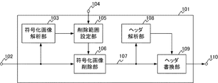
以下、図1を参照して、本発明の実施形態1における動画像編集装置について説明する。動画像編集装置101には、全てのフレームのピクチャタイプがIDRピクチャである動画像が入力される。以下、当該動画像を本明細書では「符号化画像」と呼ぶ。動画像編集装置101には符号化画像102が入力され、編集符号化画像110が出力される。動画像編集装置101は、符号化画像解析部103、外部からの設定入力を受け付ける外部設定入力104、削除範囲設定部105、符号化画像102から削除符号化画像107を生成する符号化画像削除部106、ヘッダ解析部108、ヘッダ書換部109を有する。符号化画像解析部103、削除範囲設定部105、符号化画像削除部106により動画像編集部として機能する。
[Embodiment 1]
Hereinafter, the moving image editing apparatus according to the first embodiment of the present invention will be described with reference to FIG. A moving image in which the picture type of all frames is an IDR picture is input to the moving
なお、図1の動画像編集装置101において、各ブロックは専用ロジック回路やメモリを用いてハードウェア的に構成されてもよい。或いは、メモリに記憶されている処理プログラムをCPU等のコンピュータが実行することにより、ソフトウェア的に構成されてもよい。
In the moving
次に、図1に示す各ブロックの動作について説明する。本実施形態の動画像編集装置101は、「ITU-T Rec. H.264 | ISO/IEC 14496-10 Advanced Video Coding」(以後「H.264」という)で符号化された動画を編集することができる。符号化画像解析部103は、入力された符号化画像102の構成情報としてストリーム中の各ピクチャの位置情報を、削除範囲設定部105へ出力する。削除範囲設定部105は、符号化画像102からの構成情報を元に、ユーザからの指定等の外部設定入力104に従って、符号化画像102の削除範囲のピクチャ位置情報を符号化画像削除部106へ出力する。
Next, the operation of each block shown in FIG. 1 will be described. The moving
符号化画像削除部106は、削除範囲設定部105で指示された削除開始点から削除終了点までの削除範囲のフレームを符号化画像102から削除して、削除符号化画像107をヘッダ解析部108とヘッダ書換部109へ出力する。
The encoded
ヘッダ解析部108は、削除符号化画像107の削除開始点の直前のフレームのヘッダと削除終了点の直後のフレームのヘッダ、即ち、削除により新たに隣接し合う(連続する)こととなったフレームのヘッダを解析する。なお、当該解析に当たり、削除範囲設定部105から上述の削除範囲のピクチャ位置情報を取得しても良い。ヘッダ解析部108は、各フレームのヘッダ内のピクチャ識別子であるidr_pic_idとスライスタイプであるslice_typeを抽出し、ヘッダ書換部109に出力する。
The
ヘッダ書換部109は、取得したピクチャ識別子であるidr_pic_idとslice_typeをチェックする。削除開始点の直前のフレーム(第1のフレーム)のidr_pic_idと削除終了点の直後のフレーム(第2のフレーム)のidr_pic_idとが一致した場合、削除符号化画像107のヘッダ中のidr_pic_idおよびslice_typeを書き換えて、編集符号化画像110を出力する。なお、ヘッダ書換部109における具体的なヘッダの書き換え方法は後述する。
The
続いて、実施形態1における削除符号化画像107について、図2を参照して説明を行う。図1の符号化画像削除部106は、削除範囲設定部105で指示された削除範囲(例えば、削除開始点201から削除終了点202までの範囲)の符号化画像を削除して、削除符号化画像107を生成する。
Next, the deletion encoded
ここでidr_pic_idを重複しない値に変更できるようにするために、idr_pic_idの値は少なくとも5ビット以上必要である。しかし、idr_pic_idが必ず5ビット以上であるという保証はない。そこで本実施形態では、idr_pic_idが5ビット以上の値をとれないことがないように、ゴロム符号化されているslice_typeを変更することでビットを余らせ、その分idr_pic_idに割り振る。 Here, in order to be able to change idr_pic_id to a non-overlapping value, the value of idr_pic_id needs to be at least 5 bits. However, there is no guarantee that idr_pic_id is always 5 bits or more. Therefore, in this embodiment, so that idr_pic_id cannot take a value of 5 bits or more, bits are left by changing slice_type that has been Golomb-encoded and allocated to idr_pic_id accordingly.
H.264規格によると、全てのフレームのピクチャタイプがIDRである場合、slice_typeが取りうる値は、2もしくは7である。ここで、"2"とは、「スライスヘッダの設定はそのスライスだけに有効」という意味である。一方"7"とは「スライスヘッダの設定は、フレーム内のスライスに有効」という意味である。フレーム内に1つしかスライスが存在しない場合や、マルチスライスであってもピクチャ内の設定を変えない場合(即ち、複数スライスの設定が同一の場合)は"7"でよい。そこで、本発明においては、ストリーム生成時にslice_type=7(第1のスライスタイプ)と設定し、編集時にslice_type=2(第2のスライスタイプ)に変更することで余裕ビットを生み出す。 H. According to the H.264 standard, when the picture type of all frames is IDR, the value that slice_type can take is 2 or 7. Here, “2” means “the setting of the slice header is valid only for the slice”. On the other hand, “7” means “the setting of the slice header is valid for the slice in the frame”. “7” may be used when there is only one slice in a frame, or when settings in a picture are not changed even in the case of multi-slices (that is, when settings of a plurality of slices are the same). Therefore, in the present invention, a margin bit is generated by setting slice_type = 7 (first slice type) when generating a stream and changing to slice_type = 2 (second slice type) when editing.
図8に示されるように、データ値"7"はゴロム符号化において7ビットで表される。データ値"2"は、ゴロム符号化において3ビットで表される。そこで、ヘッダの書き換えが生じた場合、slice_typeを"7"から"2"に変更することで4ビット削減され、その削減された4ビットをidr_pic_idへと振り分け可能である。 As shown in FIG. 8, the data value “7” is represented by 7 bits in Golomb coding. The data value “2” is represented by 3 bits in Golomb coding. Therefore, when the header is rewritten, the slice_type is changed from “7” to “2” to reduce 4 bits, and the reduced 4 bits can be distributed to idr_pic_id.
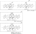
次に、図3と図4を参照して、図1のヘッダ解析部108におけるヘッダ解析処理と、ヘッダ書換部109におけるヘッダ書換処理動作について詳細に説明する。図3は、ヘッダ解析部108およびヘッダ書換部109の制御動作の流れを示したフローチャートである。該フローチャートに対応する処理は、例えば、ヘッダ解析部108及びヘッダ書換部109として機能するプロセッサが対応するプログラム(装置のROM等に格納)を実行することにより実現できる。図4は、図2で示した符号化画像102と削除符号化画像107と編集符号化画像110のストリームの中身をフレーム単位で示した一構成例である。
Next, the header analysis processing in the
図3におけるS301では、ヘッダ書換部109はスライス削除開始点の直前のフレームのidr_pic_idをヘッダ解析部108から取得する。ここで、取得したidr_pic_idの値を「n」とする。ここで、符号化画像102の構成を図4に示すものと仮定すると、図4の符号化画像102における削除開始点201の直前のフレーム401のidr_pic_idの値は「2」、即ちn=2となる。
In S <b> 301 in FIG. 3, the
図3のS302では、ヘッダ書換部109は削除終了点の直後のフレームのslice_typeをヘッダ解析部108から取得する。ここで取得したslice_typeの値を「a」とする。例えば、図4における削除終了点202の直後のフレーム402のslice_typeは7、即ちa=7である。
In S <b> 302 of FIG. 3, the
S303では、ヘッダ書換部109はステップ302で取得した削除終了点の直後のフレームのslice_typeの値aが、7であるか否かを判定する。もし削除終了点の直後のフレームのslice_typeの値aが7である場合(S303で「YES」)、ステップ304に進む。一方、削除終了点の直後のフレームのslice_typeの値aが7でない場合(S303で「NO」)、ステップ310に進む。例えば、図4における削除終了点202の直後のフレーム402のslice_typeは7であるため、ステップ304に進む。
In step S <b> 303, the
S304では、ヘッダ書換部109は削除終了点の直後のフレームのidr_pic_idをヘッダ解析部108から取得する。取得したidr_pic_idの値を「m」とする。例えば、図4における削除終了点202の直後のフレーム402のidr_pic_idを取得する。ここで取得したidr_pic_idは2、即ちm=2である。
In S <b> 304, the
S305では、ヘッダ書換部109ははS301で取得した削除開始点の直前のフレームのidr_pic_idの値nと、S304で取得した削除終了点の直後のフレームのidr_pic_idの値mとを比較する。もし、nとmとが不一致の場合(S305で「NO」)、idr_pic_idを修正する必要がないので処理を終了する。一方、nとmとが一致する場合(S305で「YES」)、ステップ306に進む。例えば、図4における削除符号化画像107の削除開始点201の直前のフレーム401のidr_pic_idと、削除終了点202の直後のフレーム402のidr_pic_idとは、共に「2」で一致しているため、S306に進む。
In S305, the
S306では、ヘッダ書換部109は削除終了点の直後のフレームのidr_pic_idのビット長をヘッダ解析部108から取得する。取得したidr_pic_idのビット長を「b」とする。例えば、図4における削除終了点202の直後のフレーム402のidr_pic_idのビット長を取得する。取得したidr_pic_idのビット長は、図8のゴロム符号とデータ値の範囲の関係より3ビットであることが分かる。
In S <b> 306, the
S307では、ヘッダ書換部109はS306で取得した削除終了点の直後のフレームのidr_pic_idのビット長bが第1のビット長である29ビット以下であるか否かを判定する。H.264規格によるidr_pic_idの最大ビット長は33ビットであり、現行が30ビット以上であった場合は4ビット拡張できない。即ち、第1のビット長は、2つのスライスタイプのビット長の差分と、idr_pic_idの最大ビット長とに基づいて決定される値である。S307では、処理対象の符号化画像102が、このような場合に該当するか否かを判定する。もし、削除終了点の直後のフレームのidr_pic_idのビット長bが第1のビット長以下である場合(S307で「YES」)ステップ308に進む。S307では、ヘッダ書換部109は削除終了点の直後のフレームのidr_pic_idのビット長のbが29ビットよりも大きい場合(S307で「NO」)ステップ318に進む。例えば、図4における削除終了点202の直後のフレーム402のidr_pic_idのビット長は3ビットであり、29ビット以下であるためS308に進む。
In S307, the
S308では、ヘッダ書換部109は削除終了点の直後のフレームのslice_typeを7から2に変更する。この処理を行うことで、4ビットの余裕ができる。例えば、図4における削除終了点202の直後のフレーム402のslice_typeのみ7から2に変更する。続くS309では、ヘッダ書換部109は削除終了点の直後のフレームのidr_pic_idのビット長を4ビット拡張する。例えば、図4における削除終了点202の直後のフレーム402のidr_pic_idのビット長を4ビット拡張して、3ビットから7ビットにする。その後、S318に進む。
In S308, the
S303でNOと判定された後、S310では、ヘッダ書換部109はS302で取得した削除終了点の直後のフレームのslice_typeの値aが2であるか否かを判定する。この時考慮すべきは、符号化画像102を作成時にslice_typeが7に設定されていた点である。即ち、slice_typeが2であった場合には、当該フレームは過去に編集されているフレームと考えることができる。つまり、すでにidr_pic_idが4ビット拡張されていると考えてよい。そこで、削除終了点の直後のフレームのslice_typeの値aが2である場合(S310で「YES」)、ステップ311に進む。一方、削除終了点の直後のフレームのslice_typeの値aが2でない場合(S310で「NO」)、本発明適用外の符号化画像102として処理を終了する。
After NO is determined in S303, in S310, the
続くS311では、ヘッダ書換部109は削除終了点の直後のフレームのidr_pic_idをヘッダ解析部108から取得する。取得したidr_pic_idをmとする。S312では、ヘッダ書換部109はステップ301で取得した削除開始点の直前のフレームのidr_pic_idのnと、S311で取得した削除終了点の直後のフレームのidr_pic_idのmを比較する。不一致の場合(S312で「NO」)は、idr_pic_idを修正する必要がないので処理を終了する。一方、一致の場合(S312で「YES」)、S313に進む。
In subsequent S <b> 311, the
S313では、ヘッダ書換部109は削除終了点の直後のフレームのidr_pic_idのビット長をヘッダ解析部108から取得する。取得したidr_pic_idのビット長をbとする。続くS314では、ヘッダ書換部109はS313で取得した削除終了点の直後のフレームのidr_pic_idのビット長のbが第2のビット長である5ビット以上であるか否かを判定する。これはidr_pic_idが取り得る最小ビット長は1ビットだからである。即ち、第2のビット長は、2つのスライスタイプのビット長の差分と、idr_pic_idの最小ビット長とに基づいて決定される値である。
In S313, the
削除終了点の直後のフレームのidr_pic_idのビット長bが第2のビット長以上である場合(S314で「YES」)はステップ315に進む。一方、削除終了点の直後のフレームのidr_pic_idのビット長のbが5よりも小さい場合(S314で「NO」)、S317に進む。 If the bit length b of idr_pic_id of the frame immediately after the deletion end point is greater than or equal to the second bit length (“YES” in S314), the process proceeds to step 315. On the other hand, if the bit length b of idr_pic_id of the frame immediately after the deletion end point is smaller than 5 (“NO” in S314), the process proceeds to S317.
S315では、ヘッダ書換部109は削除終了点の直後のフレームのslice_typeを2から7に変更する。続くS316では、ヘッダ書換部109は削除終了点の直後のフレームのidr_pic_idのビット長を4ビット縮小する。一方、S317では、ヘッダ書換部109はS313で取得した削除終了点の直後のフレームのidr_pic_idのビット長bが3ビット以下であるか否かを判定する。削除終了点の直後のフレームのidr_pic_idのビット長bが3ビット以下である場合(S317で「YES」)、本発明適用外の符号化画像102として処理を終了する。一方、削除終了点の直後のフレームのidr_pic_idのビット長bが3ビットよりも大きい場合(S317で「NO」)、S318に進む。この場合は、ビット長bは4ビット(第3のビット長)である。
In S315, the
S318では、ヘッダ書換部109は削除終了点の直後のフレームのidr_pic_idを変更する。但し、削除終了点の直後のフレームのidr_pic_idを変更する値は、削除開始点の直前のフレームのidr_pic_idの値nとは異なる値に変更する。
In S318, the
例えば、図4における削除終了点202の直後のフレーム402のidr_pic_idを変更する場合、変更する値は、削除開始点の直前のフレームのidr_pic_idの2とは異なる7に変更する。本実施形態では、idr_pic_idを2から7へと変更しているが、変更後の値は2以外の値であれば良い。idr_pic_idを4ビット拡張することにより、図8で示されているデータ値の範囲は"1−2"の2種類から"7−14"の8種類へ増える。よって、本実施形態によれば"7−14"の8種類のidr_pic_idが選択可能となる。その結果、idr_pic_idが2、slice_typeが7のフレーム402を、idr_pic_idが7、slice_typeが2のフレーム404に変更した編集符号化画像110が生成される。なお、図10は、idr_pic_idのビット拡張前後のゴロム符号及びデータ値の例を示している。図10では、4ビット拡張によりデータ値「2」から「11」へ変更されている。また、図11は、idr_pic_idのビット縮小前後のゴロム符号及びデータ値の例を示している。図11では、4ビット縮小によりデータ値「12」から「2」へ変更されている。
For example, when the idr_pic_id of the
以上の説明では、S305およびS312において、idr_pic_idの値を比較しているが、比較自体を行わないという方法もある。つまり、idr_pic_idの値が一致していない場合でも、次の処理S306またはS313の処理へと進んでもよい。このように動作することで常にslice_typeを修正することになるが、例外判定処理が減ることで処理ステップが減少する利点が得られる。 In the above description, the values of idr_pic_id are compared in S305 and S312, but there is a method in which the comparison itself is not performed. That is, even if idr_pic_id values do not match, the process may proceed to the next process S306 or S313. By operating in this way, the slice_type is always corrected, but the advantage that the number of processing steps is reduced by reducing the exception determination processing can be obtained.
なお、以上の説明では、符号化画像がすべてIDRで構成されていた場合(ALL−IDRピクチャ)を説明したが、発明の実施形態は当該構成に限定されるものではない。編集後の削除符号化画像107において隣り合うIDRピクチャが存在する可能性があれば、本願発明が適用可能である。即ち、IDRピクチャを含む動画像であれば、同様に本発明を適用可能であり、本願発明の適用対象が全てIDRピクチャで構成される動画像だけに限定されることはない。
In the above description, the case where all the encoded images are configured by IDR (ALL-IDR picture) has been described, but the embodiment of the present invention is not limited to this configuration. If there is a possibility that adjacent IDR pictures exist in the deleted encoded
以上の本実施形態によれば、符号化画像の編集後にピクチャ識別子が同一のIDRピクチャが連続してしまう場合であっても、単一のフレームのヘッダ内のデータを変更することにより、効率的にピクチャ識別子の変更を行うことができる。 According to the present embodiment described above, even if IDR pictures having the same picture identifier are consecutive after editing of the encoded image, it is possible to improve efficiency by changing the data in the header of a single frame. The picture identifier can be changed.
[実施形態2]
実施形態1では、入力された動画の一部のシーケンスを削除することにより編集を行う場合について説明した。これに対し実施形態2では、2つの動画を結合することにより新たな動画を生成する編集を行う場合について説明する。
[Embodiment 2]
In the first embodiment, a case has been described in which editing is performed by deleting a partial sequence of an input moving image. In contrast, in the second embodiment, a case will be described in which editing is performed to generate a new moving image by combining two moving images.
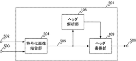
図5は、発明の実施形態2に対応する動画像編集装置の構成を示す。動画像編集装置501には、全てのフレームのピクチャタイプがIDRピクチャである符号化画像502及び503が入力され、編集符号化画像506が出力される。動画像編集装置501は、符号化画像502、503から結合符号化画像505を生成する符号化画像結合部504、ヘッダ解析部108、ヘッダ書換部109を有する。本実施形態では、符号化画像結合部504が動画像編集部として機能する。なお、図5の動画像編集装置501において、各ブロックは専用ロジック回路やメモリを用いてハードウェア的に構成されてもよい。或いは、メモリに記憶されている処理プログラムをCPU等のコンピュータが実行することにより、ソフトウェア的に構成されてもよい。
FIG. 5 shows a configuration of a moving image editing apparatus corresponding to the second embodiment of the invention. The moving
次に、図5に示す各ブロックの動作について説明する。符号化画像結合部504は、入力される符号化画像502と符号化画像503とを結合して、結合符号化画像505を出力する。ヘッダ解析部108は、結合符号化画像505の結合点直前のフレームのヘッダと結合点直後のフレームのヘッダ、即ち、結合により新たに隣接し合う(連続する)こととなったフレームのヘッダを解析する。ヘッダ解析部108は、結合点前後の各IDRピクチャのヘッダ内のピクチャ識別子であるidr_pic_idと結合点前後の各フレームのヘッダ内のスライスタイプであるslice_typeを抽出し、ヘッダ書換部109に出力する。
Next, the operation of each block shown in FIG. 5 will be described. The encoded
ヘッダ書換部109は、取得したidr_pic_idとslice_typeをチェックする。結合点直前のフレーム(第1のフレーム)のidr_pic_idと、結合点直後のフレーム(第2のフレーム)のidr_pic_idとが一致した場合に、結合符号化画像505のヘッダ中のidr_pic_idおよびslice_typeを書き換えて、編集符号化画像506を出力する。なお、ヘッダ書換部109における具体的なヘッダの書き換え方法は後述する。
The
続いて、実施形態2における結合符号化画像505について、図6を参照して説明を行う。まず、符号化画像502は、ストリームA(601)で構成され、符号化画像503は、ストリームB(602)で構成されている。本実施形態では、符号化画像結合部504が、ストリームA(601)の後にストリームB(602)を結合して結合符号化画像505を生成する場合を説明する。なお、結合符号化画像505のストリームA(601)とストリームB(602)の境界を、結合点603とする。
Next, the joint encoded
次に図7を参照して、図5のヘッダ解析部108におけるヘッダ解析処理と、ヘッダ書換部109におけるヘッダ書換処理動作について詳細に説明する。図7は、ヘッダ解析部108およびヘッダ書換部109の制御動作の流れを示したフローチャートである。該フローチャートに対応する処理は、例えば、ヘッダ解析部108及びヘッダ書換部109として機能するプロセッサが対応するプログラム(装置のROM等に格納)を実行することにより実現できる。なお、図7に示す各ステップのうち、図3と同一の参照番号が振られているステップは、図3で説明した処理と同一処理が実行されるステップである。
Next, the header analysis processing in the
図7におけるS701では、ヘッダ書換部109は結合点の直前のフレームのidr_pic_idをヘッダ解析部108から取得する。ここで取得したidr_pic_idの値を「n」とする。続くS702では、ヘッダ書換部109は結合点の直後のフレームのslice_typeを取得する。取得したslice_typeの値を「a」とする。
In S <b> 701 in FIG. 7, the
ステップ303では、ヘッダ書換部109がステップ702で取得した結合点の直後のフレームのslice_typeの値aが7であるか否かを判定する。もし、結合点の直後のフレームのslice_typeの値aが7である場合(S303で「YES」)、ステップ704に進む。一方、結合点の直後のフレームのslice_typeの値aが7でない場合(S303で「NO」)、ステップ310に進む。
In
S704では、ヘッダ書換部109は結合点の直後のフレームのidr_pic_idをヘッダ解析部108から取得する。ここで取得したidr_pic_idの値を「m」とする。続くステップ305では、ヘッダ書換部109はS701で取得した結合点の直前のフレームのidr_pic_idの値nと、ステップ704で取得した結合点の直後のフレームのidr_pic_idの値mとを比較する。もし、nとmとが不一致の場合(S305で「NO」)、idr_pic_idを修正する必要がないので処理を終了する。一方、nとmとが一致する場合(S305で「YES」)、S706に進む。
In S <b> 704, the
S706では、ヘッダ書換部109は結合点の直後のフレームのidr_pic_idのビット長をヘッダ解析部108から取得する。取得したidr_pic_idのビット長を「b」とする。続くS307では、ヘッダ書換部109はS706で取得した結合点の直後のフレームのidr_pic_idのビット長のbが29ビット以下であるか否かを判定する。もし、結合点の直後のフレームのidr_pic_idのビット長のbが29ビット以下である場合(S307で「YES」)、ステップ708に進む。一方、結合点の直後のフレームのidr_pic_idのビット長のbが29ビットよりも大きい場合(S307で「NO」)、S718に進む。
In S706, the
S708では、ヘッダ書換部109は結合点の直後のフレームのslice_typeを7から2に変更する。この処理を行うことで、4ビットの余裕ができる。続くS709では、ヘッダ書換部109は結合点の直後のフレームのidr_pic_idのビット長を4ビット拡張する。その後、S718に進む。
In S708, the
S303でNOと判定された後、Sステップ310では、ヘッダ書換部109はステップ702で取得した結合点の直後のフレームのslice_typeのaが2であるか否かを判定する。このとき考慮すべきは、符号化画像502および符号化画像503を作成時に、slice_typeが7に設定されていた点である。即ち、slice_typeが2であった場合には、当該フレームは過去に編集されているフレームと考えることができる。つまり、すでにidr_pic_idが4ビット拡張されていると考えてよい。そこで、結合点の直後のフレームのslice_typeの値aが2である場合(S310で「YES」)はS711に進む。一方、結合点の直後のフレームのslice_typeの値aが2でない場合(S310で「NO」)、本発明適用外の符号化画像502および符号化画像503として処理を終了する。
After NO is determined in S303, in S310, the
続くS711では、ヘッダ書換部109は結合点の直後のフレームのidr_pic_idをヘッダ解析部108から取得する。取得したidr_pic_idをmとする。ステップ312では、ヘッダ書換部109はS701で取得した結合点の直前のフレームのidr_pic_idのnと、ステップ711で取得した結合点の直後のフレームのidr_pic_idのmとを比較する。不一致の場合(S312で「NO」)、idr_pic_idを修正する必要がないので処理を終了する。一方、一致の場合(S312で「YES」)、S713に進む。
In subsequent S <b> 711, the
S713では、ヘッダ書換部109は結合点の直後のフレームのidr_pic_idのビット長をヘッダ解析部108から取得する。取得したidr_pic_idのビット長をbとする。続くステップ314では、ヘッダ書換部109はS713で取得した結合点の直後のフレームのidr_pic_idのビット長のbが5ビット以上であるか否かを判定する。結合点の直後のフレームのidr_pic_idのビット長のbが5ビット以上である場合(S314で「YES」)、S715に進む。結合点の直後のフレームのidr_pic_idのビット長のbが5ビットよりも小さい場合(S314で「NO」)、S317に進む。
In S713, the
S715では、ヘッダ書換部109は結合点の直後のフレームのslice_typeを2から7に変更する。続くS716では、ヘッダ書換部109は結合点の直後のフレームのidr_pic_idのビット長を4ビット縮小する。一方、S317では、ヘッダ書換部109はS713で取得した結合点の直後のフレームのidr_pic_idのビット長のbが3ビット以下であるか否かを判定する。結合点の直後のフレームのidr_pic_idのビット長のbが3ビット以下である場合(S317で「YES」)、本発明適用外の符号化画像502および符号化画像503として処理を終了する。一方、結合点の直後のフレームのidr_pic_idのビット長のbが3ビットよりも大きい場合(S317で「NO」)、S718に進む。なお、この場合はビット長bは4ビットである。S718では、結合点の直後のフレームのidr_pic_idを変更する。
In S715, the
なお、上記S305および312においてidr_pic_idの値を比較しているが、比較自体を行わないという方法もある。つまり、idr_pic_idの値が一致していない場合でも、次の処理S706またはS713の処理へと進んでもよい。このように動作することで常にslice_typeを修正することになるが、例外判定処理が減ることで処理ステップが減少する利点が得られる。 In addition, although the value of idr_pic_id is compared in S305 and 312 above, there is also a method in which the comparison itself is not performed. That is, even if idr_pic_id values do not match, the process may proceed to the next process S706 or S713. By operating in this way, the slice_type is always corrected, but the advantage that the number of processing steps is reduced by reducing the exception determination processing can be obtained.
なお、以上の説明では、符号化画像がすべてIDRで構成されていた場合(ALL−IDRピクチャ)を説明したが、発明の実施形態は当該構成に限定されるものではない。編集後の結合符号化画像505において隣り合うIDRピクチャが存在する可能性があれば、本願発明が適用可能である。即ち、IDRピクチャを含む動画像であれば、同様に本発明を適用可能であり、本願発明の適用対象が全てIDRピクチャで構成される動画像だけに限定されることはない。
In the above description, the case where all the encoded images are configured by IDR (ALL-IDR picture) has been described, but the embodiment of the present invention is not limited to this configuration. If there is a possibility that adjacent IDR pictures exist in the combined encoded
以上の本実施形態によれば、符号化画像の結合後にピクチャ識別子が同一のIDRピクチャが連続してしまう場合であっても、単一のフレームのヘッダ内のデータを変更することにより、効率的にピクチャ識別子の変更を行うことができる。 According to the present embodiment described above, even if IDR pictures having the same picture identifier are consecutive after the combination of encoded images, it is efficient by changing the data in the header of a single frame. The picture identifier can be changed.
[実施形態3]
次に、図12及び図13を参照して実施形態1の変形例として、実施形態3を説明する。図13は、ヘッダ解析部108およびヘッダ書換部109の制御動作の流れを示したフローチャートである。図中、図3と同一の参照番号が振られているステップは、図3で説明した処理と同一処理が実行されるステップである。図12では、図3のS318の代わりに、S1201とS1202とを設けた点で処理が異なる。
[Embodiment 3]
Next, a third embodiment will be described as a modification of the first embodiment with reference to FIGS. 12 and 13. FIG. 13 is a flowchart showing the flow of control operations of the
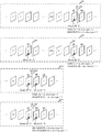
図13は、実施形態1の処理を行った後の編集符号化画像110を再度編集する場合の、削除符号化画像1305と再編集符号化画像1306のストリームの中身をフレーム単位で示した図である。図中、図4に示した要素に対応する要素については説明が共通するので同一の参照番号を付した。図13における編集符号化画像110は実施形態1の処理が既に行われた編集符号化画像である。図13における符号化画像中の削除範囲は、削除開始点1303から削除終了点1304である。図13における削除開始点1303の直前のフレーム(第1のフレーム)1301のidr_pic_idは2、削除終了点の直後のフレーム(第2のフレーム)401のidr_pic_idも2である。以下、実施形態1と異なる箇所のみ説明を行う。
FIG. 13 is a diagram showing the contents of the stream of the deleted encoded
図12において、S1201では、ヘッダ書換部109は削除終了点の直後から2番目のフレーム(第3のフレーム)のidr_pic_idをヘッダ解析部108から取得する。取得したidr_pic_idをpとする。例えば、図13における削除終了点1304の直後から2番目のフレーム404のidr_pic_idを取得する。取得したidr_pic_idは7である。続くS1202では、ヘッダ書換部109は削除終了点の直後のフレームのidr_pic_idを変更する。但し、削除終了点の直後のフレームのidr_pic_idを変更する値は、削除開始点の直前のフレームのidr_pic_idのn、及び、削除終了点の直後から2番目のフレームのidr_pic_idのpとは異なる値に変更する。
In FIG. 12 , in S1201, the
例えば、図13における削除終了点1304の直後のフレーム401のidr_pic_idを変更する場合を考える。このとき、変更後の値は、削除開始点の直前のフレーム1301のidr_pic_idの2、及び、削除終了点の直後から2番目のフレーム404のidr_pic_idの7とは異なる値でなくてはならず、図13では8に変更した場合を示している。以上の結果、idr_pic_idが2、slice_typeが7のフレーム401を、idr_pic_idが8、slice_typeが2のフレーム1302に変更した再編集符号化画像1306が生成される。
For example, consider a case where idr_pic_id of the
なお、実施形態2においても、S718の代わりにS1201及びS1202を実行することで、結合点の直後のフレームのidr_pic_idと、その後に続くフレームのidr_pic_idとの重複を回避することができる。 Also in the second embodiment, by executing S1201 and S1202 instead of S718, it is possible to avoid duplication of idr_pic_id of the frame immediately after the coupling point and idr_pic_id of the subsequent frame.
以上の本実施形態によれば、編集後の符号化画像において、ヘッダが書き換えられるフレームの後続フレームのピクチャ識別子との重複も防止することができる。 According to the present embodiment described above, in the encoded image after editing, duplication with the picture identifier of the subsequent frame of the frame whose header is rewritten can be prevented.
以上、本発明の好ましい実施形態について説明したが、本発明はこれらの実施形態に限定されず、その要旨の範囲内で種々の変形及び変更が可能である。なお、実施形態1から3において説明した動画像編集装置は、例えば、カメラ、携帯電話、パソコンなどの動画を取り扱うことができるものであればどのような装置であっても良い。 As mentioned above, although preferable embodiment of this invention was described, this invention is not limited to these embodiment, A various deformation | transformation and change are possible within the range of the summary. The moving image editing apparatus described in the first to third embodiments may be any apparatus that can handle moving images such as a camera, a mobile phone, and a personal computer.
(その他の実施例)
また、本発明は、以下の処理を実行することによっても実現される。即ち、上述した実施形態の機能を実現するソフトウェア(プログラム)を、ネットワーク又は各種記憶媒体を介してシステム或いは装置に供給し、そのシステム或いは装置のコンピュータ(またはCPUやMPU等)がプログラムを読み出して実行する処理である。
(Other examples)
The present invention can also be realized by executing the following processing. That is, software (program) that realizes the functions of the above-described embodiments is supplied to a system or apparatus via a network or various storage media, and a computer (or CPU, MPU, or the like) of the system or apparatus reads the program. It is a process to be executed.
Claims (10)
前記第1の動画像と前記第2の動画像の結合点の前後に隣接する第1のフレーム及び第2のフレームのピクチャ識別子とスライスタイプとを取得する取得手段と、
前記取得手段により取得された前記第1のフレームのピクチャ識別子と前記第2のフレームのピクチャ識別子とが一致するか否かを判定し、一致する場合に、前記第2のフレームのピクチャ識別子を、前記第1のフレームのピクチャ識別子と異なる値に変更する変更手段とを備え、
前記変更手段は、前記第2のフレームのスライスタイプが第1のスライスタイプと一致する場合、前記第2のフレームのスライスタイプを前記第1のスライスタイプよりもビット長が短い第2のスライスタイプへ変更する処理を行うとともに、前記第2のフレームのピクチャ識別子を、前記一致するピクチャ識別子よりも長いビット長に変更する処理を行うことを特徴とする画像処理装置。 An apparatus for performing processing for combining a first moving image and a second moving image,
Obtaining means for obtaining a picture identifier and a slice type of the first frame and the second frame adjacent to each other before and after a connection point between the first moving image and the second moving image;
It is determined whether or not the picture identifier of the first frame and the picture identifier of the second frame acquired by the acquisition unit match, and if they match, the picture identifier of the second frame is Changing means for changing to a value different from the picture identifier of the first frame,
When the slice type of the second frame matches the first slice type, the changing unit changes the slice type of the second frame to a second slice type having a bit length shorter than that of the first slice type. And an image processing apparatus for performing a process of changing a picture identifier of the second frame to a bit length longer than the matching picture identifier.
前記第1のビット長は、前記第1のスライスタイプのビット長と前記第2のスライスタイプのビット長との差分と、前記ピクチャ識別子が取り得る最大ビット長とに基づいて決定されることを特徴とする請求項1に記載の画像処理装置。 The changing means is the case where the slice type of the second frame matches the first slice type, and the bit length of the picture identifier of the second frame is equal to or less than the first bit length, Changing the picture identifier of the second frame to a bit length longer than the matching picture identifier;
The first bit length is determined based on a difference between a bit length of the first slice type and a bit length of the second slice type and a maximum bit length that can be taken by the picture identifier. The image processing apparatus according to claim 1, wherein:
前記第1の動画像と前記第2の動画像の結合点の前後に隣接する第1のフレーム及び第2のフレームのピクチャ識別子とスライスタイプとを取得する取得手段と、
前記取得手段により取得された前記第1のフレームのピクチャ識別子と前記第2のフレームのピクチャ識別子とが一致するか否かを判定し、一致する場合に、前記第2のフレームのピクチャ識別子を、前記第1のフレームのピクチャ識別子と異なる値に変更する変更手段とを備え、
前記変更手段は、前記第2のフレームのスライスタイプが第2のスライスタイプと一致する場合、前記第2のフレームのスライスタイプを前記第2のスライスタイプよりもビット長が長い第1のスライスタイプへ変更する処理を行うとともに、前記第2のフレームのピクチャ識別子を、前記一致するピクチャ識別子よりも短いビット長に変更する処理を行うことを特徴とする画像処理装置。 An apparatus for performing processing for combining a first moving image and a second moving image,
Obtaining means for obtaining a picture identifier and a slice type of the first frame and the second frame adjacent to each other before and after a connection point between the first moving image and the second moving image;
It is determined whether or not the picture identifier of the first frame and the picture identifier of the second frame acquired by the acquisition unit match, and if they match, the picture identifier of the second frame is Changing means for changing to a value different from the picture identifier of the first frame,
When the slice type of the second frame matches the second slice type, the changing unit changes the slice type of the second frame to a first slice type having a bit length longer than that of the second slice type. And an image processing apparatus for performing a process of changing a picture identifier of the second frame to a bit length shorter than the matching picture identifier.
前記第2のビット長は、前記第1のスライスタイプのビット長と前記第2のスライスタイプのビット長との差分と、前記ピクチャ識別子が取り得る最小ビット長とに基づいて決定されることを特徴とする請求項4に記載の画像処理装置。 In the case where the slice type of the second frame matches the second slice type, and the bit length of the picture identifier of the second frame is greater than or equal to the second bit length, the changing unit , Changing the picture identifier of the second frame to a bit length shorter than the matching picture identifier,
The second bit length is determined based on a difference between the bit length of the first slice type and the bit length of the second slice type and a minimum bit length that the picture identifier can take. The image processing apparatus according to claim 4.
前記第1のフレームと前記第2のフレームは、前記IDRピクチャであって、
前記ピクチャ識別子は、前記IDRピクチャのスライスヘッダのidr_pic_idであり、前記スライスタイプは、前記スライスヘッダのslice_typeであることを特徴とする請求項1から7のいずれか1項に記載の画像処理装置。 The first moving image and the second moving image are H.264. Including frames of IDR pictures defined by the H.264 standard,
The first frame and the second frame are the IDR pictures,
The image processing apparatus according to claim 1, wherein the picture identifier is idr_pic_id of a slice header of the IDR picture, and the slice type is slice_type of the slice header.
前記第1の動画像と前記第2の動画像の結合点の前後に隣接する第1のフレーム及び第2のフレームのピクチャ識別子とスライスタイプとを取得する取得工程と、
前記取得工程において取得された前記第1のフレームのピクチャ識別子と前記第2のフレームのピクチャ識別子とが一致するか否かを判定し、一致する場合に、前記第2のフレームのピクチャ識別子を、前記第1のフレームのピクチャ識別子と異なる値に変更する変更工程とを含み、
前記変更工程では、前記第2のフレームのスライスタイプが第1のスライスタイプと一致する場合、前記第2のフレームのスライスタイプを前記第1のスライスタイプよりもビット長が短い第2のスライスタイプへ変更する処理を行うとともに、前記第2のフレームのピクチャ識別子を、前記一致するピクチャ識別子よりも長いビット長に変更する処理を行うことを特徴とする画像処理方法。 An image processing method for performing processing for combining a first moving image and a second moving image,
An acquisition step of acquiring a picture identifier and a slice type of the first frame and the second frame adjacent to each other before and after a connection point between the first moving image and the second moving image;
It is determined whether or not the picture identifier of the first frame and the picture identifier of the second frame acquired in the acquisition step match, and if they match, the picture identifier of the second frame is Changing to a value different from the picture identifier of the first frame,
In the changing step, when the slice type of the second frame matches the first slice type, the slice type of the second frame is set to a second slice type having a bit length shorter than that of the first slice type. And a process of changing the picture identifier of the second frame to a bit length longer than the matching picture identifier.
前記第1の動画像と前記第2の動画像の結合点の前後に隣接する第1のフレーム及び第2のフレームのピクチャ識別子とスライスタイプとを取得する取得工程と、
前記取得工程において取得された前記第1のフレームのピクチャ識別子と前記第2のフレームのピクチャ識別子とが一致するか否かを判定し、一致する場合に、前記第2のフレームのピクチャ識別子を、前記第1のフレームのピクチャ識別子と異なる値に変更する変更工程とを含み、
前記変更工程では、前記第2のフレームのスライスタイプが第2のスライスタイプと一致する場合、前記第2のフレームのスライスタイプを前記第2のスライスタイプよりもビット長が長い第1のスライスタイプへ変更する処理を行うとともに、前記第2のフレームのピクチャ識別子を、前記一致するピクチャ識別子よりも短いビット長に変更する処理を行うことを特徴とする画像処理方法。 An image processing method for performing processing for combining a first moving image and a second moving image,
An acquisition step of acquiring a picture identifier and a slice type of the first frame and the second frame adjacent to each other before and after a connection point between the first moving image and the second moving image;
It is determined whether or not the picture identifier of the first frame and the picture identifier of the second frame acquired in the acquisition step match, and if they match, the picture identifier of the second frame is Changing to a value different from the picture identifier of the first frame,
In the changing step, when the slice type of the second frame matches the second slice type, the slice type of the second frame is set to a first slice type having a bit length longer than that of the second slice type. And a process of changing the picture identifier of the second frame to a bit length shorter than the matching picture identifier.
Priority Applications (3)
| Application Number | Priority Date | Filing Date | Title |
|---|---|---|---|
| JP2012192292A JP6000763B2 (en) | 2012-08-31 | 2012-08-31 | Image processing apparatus and image processing method |
| US13/964,577 US9578340B2 (en) | 2012-08-31 | 2013-08-12 | Image processing apparatus, method of controlling the same, and recording medium |
| CN201310392196.9A CN103686189B (en) | 2012-08-31 | 2013-09-02 | The control method of image processing equipment and image processing equipment |
Applications Claiming Priority (1)
| Application Number | Priority Date | Filing Date | Title |
|---|---|---|---|
| JP2012192292A JP6000763B2 (en) | 2012-08-31 | 2012-08-31 | Image processing apparatus and image processing method |
Publications (3)
| Publication Number | Publication Date |
|---|---|
| JP2014049980A JP2014049980A (en) | 2014-03-17 |
| JP2014049980A5 JP2014049980A5 (en) | 2015-10-15 |
| JP6000763B2 true JP6000763B2 (en) | 2016-10-05 |
Family
ID=50187594
Family Applications (1)
| Application Number | Title | Priority Date | Filing Date |
|---|---|---|---|
| JP2012192292A Expired - Fee Related JP6000763B2 (en) | 2012-08-31 | 2012-08-31 | Image processing apparatus and image processing method |
Country Status (3)
| Country | Link |
|---|---|
| US (1) | US9578340B2 (en) |
| JP (1) | JP6000763B2 (en) |
| CN (1) | CN103686189B (en) |
Family Cites Families (12)
| Publication number | Priority date | Publication date | Assignee | Title |
|---|---|---|---|---|
| JP3561485B2 (en) * | 2000-08-18 | 2004-09-02 | 株式会社メディアグルー | Coded signal separation / synthesis device, difference coded signal generation device, coded signal separation / synthesis method, difference coded signal generation method, medium recording coded signal separation / synthesis program, and difference coded signal generation program recorded Medium |
| EP3122045B1 (en) * | 2001-11-06 | 2018-01-24 | Panasonic Intellectual Property Corporation of America | Moving picture coding method and moving picture decoding method |
| US20040141555A1 (en) * | 2003-01-16 | 2004-07-22 | Rault Patrick M. | Method of motion vector prediction and system thereof |
| US20070230565A1 (en) * | 2004-06-18 | 2007-10-04 | Tourapis Alexandros M | Method and Apparatus for Video Encoding Optimization |
| JP4784188B2 (en) | 2005-07-25 | 2011-10-05 | ソニー株式会社 | Image processing apparatus, image processing method, and program |
| JP4757840B2 (en) * | 2006-06-02 | 2011-08-24 | パナソニック株式会社 | Encoding device and editing device |
| CN101461246B (en) | 2006-06-02 | 2013-03-20 | 松下电器产业株式会社 | Coding device and editing device |
| JP5248802B2 (en) * | 2006-06-16 | 2013-07-31 | カシオ計算機株式会社 | Moving picture encoding apparatus, moving picture encoding method, moving picture decoding apparatus, moving picture decoding method, and moving picture recording apparatus |
| US20100021142A1 (en) * | 2006-12-11 | 2010-01-28 | Panasonic Corporation | Moving picture decoding device, semiconductor device, video device, and moving picture decoding method |
| JP5056560B2 (en) * | 2008-03-17 | 2012-10-24 | 富士通株式会社 | Encoding device, decoding device, encoding method, and decoding method |
| JP2010081227A (en) * | 2008-09-25 | 2010-04-08 | Toshiba Corp | Moving image decoder |
| JP5123870B2 (en) * | 2009-02-10 | 2013-01-23 | キヤノン株式会社 | Image processing method, image processing apparatus, and program |
-
2012
- 2012-08-31 JP JP2012192292A patent/JP6000763B2/en not_active Expired - Fee Related
-
2013
- 2013-08-12 US US13/964,577 patent/US9578340B2/en active Active
- 2013-09-02 CN CN201310392196.9A patent/CN103686189B/en active Active
Also Published As
| Publication number | Publication date |
|---|---|
| CN103686189A (en) | 2014-03-26 |
| CN103686189B (en) | 2017-06-23 |
| US20140064371A1 (en) | 2014-03-06 |
| JP2014049980A (en) | 2014-03-17 |
| US9578340B2 (en) | 2017-02-21 |
Similar Documents
| Publication | Publication Date | Title |
|---|---|---|
| TWI225360B (en) | Video encoding method, video decoding method, video encoding apparatus, video decoding apparatus, video encoding program, and video decoding program | |
| JP6087940B2 (en) | Signaling of state information for decoded picture buffer and reference picture list | |
| JP3902968B2 (en) | Image processing apparatus, control method therefor, computer program, and storage medium | |
| JP4917148B2 (en) | Bitstream conversion method, bitstream conversion apparatus, bitstream combination apparatus, bitstream division program, bitstream conversion program, and bitstream combination program | |
| JP7045800B2 (en) | Converting from the Open Group of Pictures to the Closed Group of Pictures in interframe video compression | |
| JP2015501098A5 (en) | ||
| JP2008066851A (en) | Unit and method for information processing, recording medium, and program | |
| JP2006203662A (en) | Moving picture coder, moving picture decoder, and coded stream generating method | |
| JPWO2007043256A1 (en) | Moving picture conversion method, moving picture conversion apparatus, moving picture conversion system, server apparatus, and program | |
| JP6000763B2 (en) | Image processing apparatus and image processing method | |
| JP2006340183A (en) | Image coding apparatus and image coding method | |
| JP2000134631A (en) | Device and method for image encoding, device and method for image decoding, and computer readable storage medium | |
| JP3984813B2 (en) | Image processing apparatus and method, computer program, and storage medium | |
| JP4708821B2 (en) | Moving picture coding apparatus, control method therefor, computer program, and storage medium | |
| JP2022092009A (en) | Video coding or video decoding device, video coding or video decoding method, program, and recording medium | |
| JP4492777B2 (en) | Video encoding device | |
| JP4757840B2 (en) | Encoding device and editing device | |
| JPH09139912A (en) | Coded data editing device and data decoder | |
| JP4154799B2 (en) | Compressed video editing apparatus and storage medium | |
| JP5189618B2 (en) | Video encoding method, video encoding apparatus, and video encoding program | |
| US7185264B2 (en) | Image processing apparatus and method therefor | |
| JP6598376B2 (en) | Encoding apparatus and encoding method | |
| JP7397360B2 (en) | Video encoding method, video encoding device and computer program | |
| JPH10215449A (en) | Signal processing unit | |
| JP2001217722A (en) | Device and method for encoding information, and computer readable storage medium |
Legal Events
| Date | Code | Title | Description |
|---|---|---|---|
| A521 | Request for written amendment filed |
Free format text: JAPANESE INTERMEDIATE CODE: A523 Effective date: 20150827 |
|
| A621 | Written request for application examination |
Free format text: JAPANESE INTERMEDIATE CODE: A621 Effective date: 20150827 |
|
| A977 | Report on retrieval |
Free format text: JAPANESE INTERMEDIATE CODE: A971007 Effective date: 20160517 |
|
| A131 | Notification of reasons for refusal |
Free format text: JAPANESE INTERMEDIATE CODE: A131 Effective date: 20160520 |
|
| A521 | Request for written amendment filed |
Free format text: JAPANESE INTERMEDIATE CODE: A523 Effective date: 20160714 |
|
| TRDD | Decision of grant or rejection written | ||
| A01 | Written decision to grant a patent or to grant a registration (utility model) |
Free format text: JAPANESE INTERMEDIATE CODE: A01 Effective date: 20160805 |
|
| A61 | First payment of annual fees (during grant procedure) |
Free format text: JAPANESE INTERMEDIATE CODE: A61 Effective date: 20160831 |
|
| R151 | Written notification of patent or utility model registration |
Ref document number: 6000763 Country of ref document: JP Free format text: JAPANESE INTERMEDIATE CODE: R151 |
|
| LAPS | Cancellation because of no payment of annual fees |