JP6000157B2 - System and method for detecting and compensating for malfunctioning inkjet in an inkjet printing apparatus - Google Patents
System and method for detecting and compensating for malfunctioning inkjet in an inkjet printing apparatus Download PDFInfo
- Publication number
- JP6000157B2 JP6000157B2 JP2013023982A JP2013023982A JP6000157B2 JP 6000157 B2 JP6000157 B2 JP 6000157B2 JP 2013023982 A JP2013023982 A JP 2013023982A JP 2013023982 A JP2013023982 A JP 2013023982A JP 6000157 B2 JP6000157 B2 JP 6000157B2
- Authority
- JP
- Japan
- Prior art keywords
- inkjet
- image
- defect
- candidate
- ink
- Prior art date
- Legal status (The legal status is an assumption and is not a legal conclusion. Google has not performed a legal analysis and makes no representation as to the accuracy of the status listed.)
- Active
Links
Images


Classifications
-
- B—PERFORMING OPERATIONS; TRANSPORTING
- B41—PRINTING; LINING MACHINES; TYPEWRITERS; STAMPS
- B41J—TYPEWRITERS; SELECTIVE PRINTING MECHANISMS, i.e. MECHANISMS PRINTING OTHERWISE THAN FROM A FORME; CORRECTION OF TYPOGRAPHICAL ERRORS
- B41J2/00—Typewriters or selective printing mechanisms characterised by the printing or marking process for which they are designed
- B41J2/005—Typewriters or selective printing mechanisms characterised by the printing or marking process for which they are designed characterised by bringing liquid or particles selectively into contact with a printing material
- B41J2/01—Ink jet
- B41J2/015—Ink jet characterised by the jet generation process
- B41J2/04—Ink jet characterised by the jet generation process generating single droplets or particles on demand
- B41J2/045—Ink jet characterised by the jet generation process generating single droplets or particles on demand by pressure, e.g. electromechanical transducers
- B41J2/04501—Control methods or devices therefor, e.g. driver circuits, control circuits
- B41J2/04543—Block driving
-
- B—PERFORMING OPERATIONS; TRANSPORTING
- B41—PRINTING; LINING MACHINES; TYPEWRITERS; STAMPS
- B41J—TYPEWRITERS; SELECTIVE PRINTING MECHANISMS, i.e. MECHANISMS PRINTING OTHERWISE THAN FROM A FORME; CORRECTION OF TYPOGRAPHICAL ERRORS
- B41J2/00—Typewriters or selective printing mechanisms characterised by the printing or marking process for which they are designed
- B41J2/005—Typewriters or selective printing mechanisms characterised by the printing or marking process for which they are designed characterised by bringing liquid or particles selectively into contact with a printing material
- B41J2/01—Ink jet
- B41J2/015—Ink jet characterised by the jet generation process
- B41J2/04—Ink jet characterised by the jet generation process generating single droplets or particles on demand
- B41J2/045—Ink jet characterised by the jet generation process generating single droplets or particles on demand by pressure, e.g. electromechanical transducers
- B41J2/04501—Control methods or devices therefor, e.g. driver circuits, control circuits
- B41J2/0451—Control methods or devices therefor, e.g. driver circuits, control circuits for detecting failure, e.g. clogging, malfunctioning actuator
-
- B—PERFORMING OPERATIONS; TRANSPORTING
- B41—PRINTING; LINING MACHINES; TYPEWRITERS; STAMPS
- B41J—TYPEWRITERS; SELECTIVE PRINTING MECHANISMS, i.e. MECHANISMS PRINTING OTHERWISE THAN FROM A FORME; CORRECTION OF TYPOGRAPHICAL ERRORS
- B41J2/00—Typewriters or selective printing mechanisms characterised by the printing or marking process for which they are designed
- B41J2/005—Typewriters or selective printing mechanisms characterised by the printing or marking process for which they are designed characterised by bringing liquid or particles selectively into contact with a printing material
- B41J2/01—Ink jet
- B41J2/015—Ink jet characterised by the jet generation process
- B41J2/04—Ink jet characterised by the jet generation process generating single droplets or particles on demand
- B41J2/045—Ink jet characterised by the jet generation process generating single droplets or particles on demand by pressure, e.g. electromechanical transducers
- B41J2/04501—Control methods or devices therefor, e.g. driver circuits, control circuits
- B41J2/04545—Dynamic block driving
-
- B—PERFORMING OPERATIONS; TRANSPORTING
- B41—PRINTING; LINING MACHINES; TYPEWRITERS; STAMPS
- B41J—TYPEWRITERS; SELECTIVE PRINTING MECHANISMS, i.e. MECHANISMS PRINTING OTHERWISE THAN FROM A FORME; CORRECTION OF TYPOGRAPHICAL ERRORS
- B41J2/00—Typewriters or selective printing mechanisms characterised by the printing or marking process for which they are designed
- B41J2/005—Typewriters or selective printing mechanisms characterised by the printing or marking process for which they are designed characterised by bringing liquid or particles selectively into contact with a printing material
- B41J2/01—Ink jet
- B41J2/015—Ink jet characterised by the jet generation process
- B41J2/04—Ink jet characterised by the jet generation process generating single droplets or particles on demand
- B41J2/045—Ink jet characterised by the jet generation process generating single droplets or particles on demand by pressure, e.g. electromechanical transducers
- B41J2/04501—Control methods or devices therefor, e.g. driver circuits, control circuits
- B41J2/04586—Control methods or devices therefor, e.g. driver circuits, control circuits controlling heads of a type not covered by groups B41J2/04575 - B41J2/04585, or of an undefined type
-
- B—PERFORMING OPERATIONS; TRANSPORTING
- B41—PRINTING; LINING MACHINES; TYPEWRITERS; STAMPS
- B41J—TYPEWRITERS; SELECTIVE PRINTING MECHANISMS, i.e. MECHANISMS PRINTING OTHERWISE THAN FROM A FORME; CORRECTION OF TYPOGRAPHICAL ERRORS
- B41J2/00—Typewriters or selective printing mechanisms characterised by the printing or marking process for which they are designed
- B41J2/005—Typewriters or selective printing mechanisms characterised by the printing or marking process for which they are designed characterised by bringing liquid or particles selectively into contact with a printing material
- B41J2/01—Ink jet
- B41J2/21—Ink jet for multi-colour printing
- B41J2/2132—Print quality control characterised by dot disposition, e.g. for reducing white stripes or banding
- B41J2/2139—Compensation for malfunctioning nozzles creating dot place or dot size errors
Description
本明細書は、一般に媒体上にインク画像を生成するプリンタに関し、より詳細には、インク画像内の不良を特定するプリンタに関する。 This specification relates generally to printers that generate ink images on media, and more particularly to printers that identify defects in ink images.
従来のプリンタの中には、動作不良のインクジェットを検知し、補償するよう構成されたものがある。動作不良のインクジェットを特定するためには、通常、特別にデザイン、配置された、複数のインク線である基準パターンの画像を受取部材の表面上に印刷しなければならない。これらの基準パターンは、プリントジョブを形成するインク画像とは別に印刷される。結果として、この基準パターンを印刷することで、生産的な印刷で使用されるリソースが部分的に吸収されてしまう。大抵の場合、プリントヘッドは数百、あるいは数千もの個々のインクジェットを含むため、動作不良のインクジェットを1つだけ特定することは至難の業である。いくつかの画像形成装置は、光学センサを用いて画像受取部材の表面の基準パターンの画像データを生成し、これらのデータを解析し、プリントヘッド内のインクジェットの位置と関連付けて、動作不良のインクジェットを特定する。光学センサ内の光センサの位置合せエラー又はセンサの校正エラーは、プリンタの動作中に、移動する媒体から生じる歪みと共に、基準パターンの画像データの解析の精度に影響を及ぼす。プリンタが、不正確にしか動作不良のインクジェットを特定することが出来ない状況では、そのプリンタは特定されたインクジェットの周辺のインクジェットを操作して、動作不良のインクジェットにより生成された、知覚される画像不良の分を補償する。しかし、不正確に特定されたインクジェットを補償することで、動作不良のインクジェットにより生成された不良を組み合わせる画像不良が生じる。結果として、インクジェット式プリンタ内の動作不良のインクジェットに対する特定及び補償の制度を改善することが有益である。 Some conventional printers are configured to detect and compensate for malfunctioning inkjets. In order to identify a malfunctioning inkjet, an image of a reference pattern, typically a plurality of ink lines, specially designed and arranged must be printed on the surface of the receiving member. These reference patterns are printed separately from the ink image forming the print job. As a result, printing this reference pattern partially absorbs the resources used in productive printing. In most cases, print heads contain hundreds or thousands of individual ink jets, and it is difficult to identify only one malfunctioning ink jet. Some image forming apparatuses use optical sensors to generate image data of a reference pattern on the surface of the image receiving member, analyze the data, and relate the ink pattern to the position of the ink jet in the print head. Is identified. Optical sensor alignment errors or sensor calibration errors within the optical sensor, along with distortions from the moving media during printer operation, affect the accuracy of the analysis of the reference pattern image data. In situations where a printer can only incorrectly identify a malfunctioning inkjet, the printer manipulates the inkjet around the identified inkjet to produce a perceived image produced by the malfunctioning inkjet. Compensate for defective parts. However, compensating for the incorrectly identified inkjet results in an image defect that combines the defects generated by the malfunctioning inkjet. As a result, it would be beneficial to improve the identification and compensation scheme for malfunctioning inkjets in inkjet printers.
別の一実施形態では、画像不良の分を補償するインクジェット式印刷装置が開発されてきた。この印刷装置は、クロス処理方向に印刷ゾーンに渡って配列された複数のインクジェットであって、それぞれが前記複数のインクジェットを通過して、処理方向に移動する画像受取面上にインク滴を射出するよう構成された、複数のインクジェットと、クロス処理方向に画像受取面に渡って構成された複数の光検知器であって、複数の光検知器のうちのそれぞれが、画像受取面から反射した光を検知するよう構成された、複数の光検知器と、複数のインクジェット及び複数の光検知器と操作可能に接続する制御装置と、を含む。この制御装置は、第1の複数の発射信号を生成して複数のインクジェットから画像受取部材上にインクを射出して第1の印刷画像を形成し、複数の光検知器を用いて第1の印刷画像に対応する画像データを生成し、この画像データを参照して第1の印刷画像内の第1の不良を特定し、画像データ内の第1の不良のクロス処理方向の位置を参照して第1の不良を生成したインクジェットの候補を特定し、クロス処理方向のインクジェットの候補に対する発射信号の生成を修正して、複数のインクジェットから画像受取面上にインクを噴霧して第2の印刷画像を形成し、複数の光検知器を用いて第2の印刷画像に対応する画像データを生成し、第1の不良のクロス処理方向の位置のうちの所定の距離以内に位置する第2の印刷画像の画像データ内で特定された第2の不良の第2のクロス処理方向の位置に応じて、インクジェットの候補以外の複数のインクジェットのうちの第2のインクジェットが、第1の不良を生成したことを特定するよう構成される。 In another embodiment, inkjet printing devices that compensate for image defects have been developed. The printing apparatus includes a plurality of ink jets arranged across a print zone in a cross processing direction, each of which passes through the plurality of ink jets and ejects ink droplets onto an image receiving surface that moves in the processing direction. A plurality of ink jets configured in such a manner as to be configured to cross the image receiving surface in the cross processing direction, and each of the plurality of light detectors reflects light reflected from the image receiving surface. A plurality of light detectors configured to detect and a control device operably connected to the plurality of ink jets and the plurality of light detectors. The control device generates a first plurality of firing signals, ejects ink from a plurality of ink jets onto an image receiving member to form a first printed image, and uses a plurality of photodetectors to form a first print image. Image data corresponding to the print image is generated, the first defect in the first print image is identified with reference to this image data, and the position of the first defect in the image data in the cross processing direction is referred to. Identify the inkjet candidate that generated the first defect, modify the firing signal generation for the inkjet candidate in the cross-process direction, and spray the ink from the plurality of inkjets onto the image receiving surface to perform the second print An image is formed, image data corresponding to the second print image is generated using a plurality of light detectors, and a second position located within a predetermined distance among the positions in the cross processing direction of the first defect In the image data of the print image A configuration in which the second inkjet of the plurality of inkjets other than the inkjet candidates has generated the first defect according to the position of the identified second defect in the second cross processing direction. Is done.
用語「画像データ」とは、マイクロプロセッサ、プロセッサ、特定用途向け集積回路(ASIC)等のデジタル装置で処理するために好適な画像受取部材の表面上のインク画像に対するデジタル表現のことを指す。画像データは、プリンタ内の光学センサからを生成することが出来る、或いはカメラ、スキャナ、コンピュータ等のプリンタの外部のデジタル装置を用いて生成することが出来る。用語「複写画像」及び「複写画像データ」とは、同じインク画像又は類似のインク画像に対応する2つ以上の画像又は一連の画像データのことを指す。複写画像同士は、互いに全く同一である必要はない。例えば、複写画像には、企業のロゴマーク又はレターヘッドのような単一の画像で印刷された文字等の個別情報を含む証券又は広告資料等の個別書類が含まれる。用語「プリントジョブ」とは、印刷画像に関する様々なジョブパラメータ、命令、デジタルデータを規定するための、プリンタに送信される一連のデータのことを指す。画像ごとのデジタルデータにより、文字や図形等の様々な画像の要素が規定される。いくつかの実施形態では、単一のプリントジョブを用いて、プリンタに単一の書類コピーを複数印刷するよう命令する。他の実施形態では、複数のプリントジョブのうちの各プリントジョブを用いて、プリンタに同じ書類のコピーを1枚印刷するよう命令する。 The term “image data” refers to a digital representation for an ink image on the surface of an image receiving member suitable for processing on a digital device such as a microprocessor, processor, application specific integrated circuit (ASIC) or the like. Image data can be generated from an optical sensor in the printer, or can be generated using a digital device external to the printer, such as a camera, scanner, or computer. The terms “copy image” and “copy image data” refer to two or more images or a series of image data corresponding to the same ink image or similar ink images. The copied images do not have to be exactly the same. For example, copy images include individual documents such as securities or advertising materials that contain individual information such as characters printed on a single image, such as a company logo or letterhead. The term “print job” refers to a series of data sent to a printer to define various job parameters, instructions, and digital data relating to a printed image. Various image elements such as characters and figures are defined by digital data for each image. In some embodiments, a single print job is used to instruct the printer to print multiple single document copies. In other embodiments, each print job of the plurality of print jobs is used to instruct the printer to print one copy of the same document.
画像受取部材の表面は、画素と呼ばれることもある、滴が付着し得る格子上の点のパターンで構成される。インクジェットアレイでは、各インクジェットがインク滴を射出し、このインク滴が画像受取部材上のクロス処理方向の所定の位置の画素に付着するよう構成される。インクジェットは、クロス処理方向に配列して、隣接する画素にインク滴を印刷して、画像受取部材に渡って連続するインクの線を形成する。 The surface of the image receiving member is composed of a pattern of dots on a grid, sometimes referred to as pixels, to which drops can adhere. In the inkjet array, each inkjet ejects an ink droplet, and the ink droplet is attached to a pixel at a predetermined position in the cross processing direction on the image receiving member. Ink jets are arranged in the cross-process direction and print ink drops on adjacent pixels to form continuous ink lines across the image receiving member.
本明細書で使用される用語「反射率の値」とは、画像受取部材上の画素から反射した光量に割り当てられた数字の値のことを指す。いくつかの実施形態では、反射率の値には、0から255までの間の整数の値が割り当てられる。反射率の値0とは、ブラックのインクで覆われた画素等の反射光の最小レベルを表し、反射率の値255とは、画像受取部材として用いられる白い用紙から反射した光等の反射光の最大レベルを表す。他の実施形態では、反射率の値は異なる数字の範囲をカバーする非整数の値でよい。いくつかの実施形態では、赤、緑、青(RGB)の値等の異なる色分解に対応する複数の数字の値を含む反射率の値が測定される。高い反射率を有する画像受取部材上の印刷されたダッシュを含むテストパターンでは、インクのダッシュに対応する画像データは、その周囲の画像受取部材より低い画像反射率の値を有する。 As used herein, the term “reflectance value” refers to a numerical value assigned to the amount of light reflected from a pixel on an image receiving member. In some embodiments, the reflectance value is assigned an integer value between 0 and 255. A reflectance value of 0 represents the minimum level of reflected light from a pixel or the like covered with black ink, and a reflectance value of 255 represents reflected light such as light reflected from white paper used as an image receiving member. Represents the maximum level. In other embodiments, the reflectance value may be a non-integer value covering a range of different numbers. In some embodiments, a reflectance value is measured that includes a plurality of numerical values corresponding to different color separations, such as red, green, blue (RGB) values. In a test pattern that includes a printed dash on an image receiving member having a high reflectance, the image data corresponding to the ink dash has a lower image reflectance value than the surrounding image receiving member.
本明細書で使用される単語「算出する」及び「特定する」には、実用するために好適な正確さ、即ち制度を有する1つ以上の位置関係の計測値を参照して得られる計算結果を得る、ハードウェア、ソフトウェア、又はハードウェアとソフトウェアとの組合せの回路の動作も含まれる。また、以下に記載する説明は、システムインクジェット式プリンタを操作して、画像受取部材の表面上に画像を印刷することと、印刷画像を表す画像データを解析して、一時的な画像不良を検知することと、に関する。本明細書に記載される趣旨は、マーキング材料のドットを用いて、画像を生成する全てのプリンタに適用可能な類似のプリンタ及びデジタル画像解析装置にも応用可能であることを理解されたい。 As used herein, the words “calculate” and “identify” include the calculation results obtained with reference to one or more measurements of positional relationships that have an accuracy suitable for practical use, that is, a system. The operation of a circuit of hardware, software, or a combination of hardware and software is also included. In addition, the explanation described below is for operating a system ink jet printer to print an image on the surface of the image receiving member, and analyzing image data representing the printed image to detect a temporary image defect. And to do. It should be understood that the spirit described herein is applicable to similar printers and digital image analyzers that can be applied to all printers that produce images using dots of marking material.
図7には、従来技術によるインクジェット式プリンタ5が示される。本明細書のため、インクジェット式プリンタでは、1つ以上のインクジェットプリントヘッドを用いて、用紙、別の印刷媒体等の画像受取部材、又は回転する画像形成ドラム又は画像形成ベルト等の間接部材にインクの滴を射出する。プリンタ5は、「相転移インク」を用いてインク画像を印刷するよう構成され、相転移インクとは、室温では実質的に個体で、画像受取部材の表面に噴霧するために相転移インクを融解温度まで加熱すると液体状態となるインクのことを意味する。本明細書で使用される液体インクとは、溶解した個体インク、加熱されたジェルインク、又は水性インク、インク乳液、インク懸濁液、インク溶液等のその他の周知のインクの形態のことを指す。
FIG. 7 shows an
プリンタ5は、制御装置50を含み、この制御装置50が画像データを処理して、制御信号をインクジェットの射出装置へ送り、インクジェット射出装置が着色剤を射出する。着色剤は、インク、又は1つ以上の染料又は顔料を含み、選択した媒体に塗布される全ての好適な物質でよい。この着色剤はブラック、又はその他の全ての所望の色でよく、いくつかのプリンタ構成により、複数の別々の着色剤を媒体に塗布する。媒体には、特に、普通紙、コート紙、光沢紙、又はOHPフィルムを含む様々な物質が全て含まれ、これらの媒体は、シート、ロール、又はその他の物理的な形式でよい。
The
プリンタ5は、直接シート式の連続媒体用の相転移インクジェット式プリンタの一例であり、このプリンタは、ロール紙ローラ8の外側に取付けられた媒体10の巻きわく等の媒体供給源から「基材」(用紙、プラスチック、又はその他の印刷可能媒体)の媒体Wの長い(即ち、実質的に連続した)ロール紙を供給するよう構成された媒体供給処理システムを含む。片面印刷に関して、プリンタ5は、媒体調整装置16、印刷ゾーン20、印刷済ロール紙調整装置80、巻き戻しユニット90に、媒体ロール紙Wを1度通して通過させる。片面印刷では、媒体供給源10は、幅プリンタ内を通って、その上を媒体が移動するローラの幅を実質的に覆う幅を有する。
The
両面印刷に関して、ロール紙反転装置84が、媒体ロール紙Wをひっくり返して、媒体の第2の側を、印刷ゾーン20、及び印刷済ロール紙調整装置80に通過させ、その後、巻き戻しユニット90がこの媒体ロール紙Wを収容する。プリンタから取り外し、その後の処理を行うために、この巻き戻しユニット90はローラにロール紙を巻きつけるよう構成される。
For duplex printing, the roll paper reversing device 84 flips the media roll paper W and passes the second side of the media through the print zone 20 and the printed roll paper conditioning device 80, after which the
必要に応じて、媒体ロール紙Wは供給源10から広げられ、種々のモータ、図示せず、が1つ以上のローラ12及びローラ26を回転させ媒体ロール紙を押し出す。媒体調整装置は、ローラ12及び予備ヒータ18を含む。ローラ12及び媒体がプリンタに内の経路に沿って移動するときに、ローラ26が広げられる媒体の張力を制御する。
As needed, the media roll W is unrolled from the
媒体印刷は、印刷ゾーン20内を進み、この印刷ゾーンが、一連のカラーモジュール、即ちカラーユニット21A、21B、21C、21Dを含む。各カラーモジュールは、効果的に媒体の幅に渡って延在し(移動する媒体に直接、即ち、中間部又はオフセット部を使用することなしに)インクを射出することが出来る。プリンタ5では、で一般にカラー印刷で使用される色、即ち、シアン、マゼンダ、イエロー、ブラック(CMYK)ごとに、各プリントヘッド1つが、単一の色のインクを射出する。このプリンタの制御装置50は、ロール紙がプリントヘッドを通過して移動するときに経路の一部分の4つのプリントヘッドの反対側である、どちらか側に位置するローラに近接して取付けられたエンコーダから、速度データを受信して、ロール紙の直線速度及びロール紙の位置を算出する。制御装置50は、これらのデータを使用して、プリントヘッド内のインクジェット射出装置を起動するための発射信号を生成して、それぞれの色のパターンと媒体上の4色の画像の位置を合わせるための適切なタイミング及び精度で、プリントヘッドがインクの4色を射出できるようにする。
Media printing proceeds within the print zone 20, which includes a series of color modules,
一般に、バー又はローラの形態をとる裏当て材24A〜24Dが、各カラーのモジュールに付随し、プリントヘッドの反対に媒体の裏側に実質的に接して配置される。各裏当て材は、裏当て材の反対のプリントヘッドから所定の距離に媒体を位置させる。
A
中間ヒータ30に続いて、定着部組立体40が媒体に熱及び/又は圧力を加えて、画像を媒体に定着させる。この定着部組立体は、高温の圧力ローラ又は非高温の圧力ローラ、放射ヒータ、加熱ランプ等を含む媒体に画像を定着させる全ての好適な装置又は機構を含む。図7の実施形態では、定着部組立体は、所定の圧力を加え、且ついくつかの実装形態では、熱を、媒体に加える「拡散器」40を含む。この拡散器40の機能は、ロール紙W上の個々のインクの小滴、インクの小滴の筋、又はインクの線を平らにすることと、圧力及び、いくつかのシステムでは、熱を用いてインクを平らにすることとである。
Following the
拡散器40は、画像側のローラ42に関連するクリーニング/オイル塗布ステーション48を含むことが出来る。このステーション48は、ローラ表面を清掃し且つ/又はある離型剤の層又はその他の材料の層をローラの表面に塗布する。離型剤の材料は、約10〜200センチポアズの粘度を有するアミノシリコーンオイルでよい。 The diffuser 40 may include a cleaning / oil application station 48 associated with the image side roller 42. This station 48 cleans the roller surface and / or applies a layer of release agent or other material to the surface of the roller. The release agent material may be an aminosilicone oil having a viscosity of about 10-200 centipoise.
印刷済媒体は、経路を辿って拡散器40を通過すると、ローラに巻きつけられてシステムから取り除かれ得る(片面印刷)、又はロール紙反転装置84に向かい、反転され、プリントヘッド、中間ヒータ、拡散器、被膜ステーションによる第2のパスへ搬送するため、次のセクションのローラへ送られる。あるプリンタ5の構成では、片面印刷を終えた媒体、又は両面印刷を終えた媒体に巻き戻しユニット90を用いてローラに巻きつけてシステムから取り除く。あるいは、媒体を他の処理ステーションに送り、そこで媒体のカット、製本、丁合、及び/又はホチキスどめ等の作業を行うことも出来る。
As the printed medium follows the path through the diffuser 40, it can be wound around a roller and removed from the system (single-sided printing), or reversed toward the roll paper reversing device 84, and the printhead, intermediate heater, It is sent to the rollers in the next section for transport to the second pass by the diffuser, coating station. In a
プリンタ5では、制御装置50が、様々なサブシステム及び構成部品に操作可能に接続して、プリンタ5の動作を管理、制御する。制御装置50は、プログラムされた命令を実行する汎用又は専用のプログラマブルプロセッサを用いて実行される。プログラムされた機能を行うよう要求される命令及びデータは、プロセッサ又は制御装置に関連するメモリに格納される。プリンタの動作を行う制御装置及び/又は印刷エンジンはプロセッサ、そのメモリ、インターフェース回路で構成される。これらの構成部品は、印刷配線回路カード上に設けられる、又は特定用途向け集積回路(ASIC)内の回路として設けられる。各回路を、別々のプロセッサを用いて実行することが出来る、又は複数の回路を同じプロセッサ上で実行することが出来る。あるいは、個別の構成部品、又は超大規模集積回路(VLSI)回路内に設けられた個別の回路を用いて、その回路を実行することが出来る。また、本明細書で説明する回路は、プロセッサ、ASIC、個別の構成部品、又はVLSI回路の組合せを用いても実行することが出来る。
In the
プリンタ5は、上記に印刷済ロール紙の画像形成に関して記載した方法と類似の方法で構成された光学画像形成システム54を含む。この光学画像形成システムは、例えば、プリントヘッド組立体のインクジェット式ノズルにより、受取り部上に噴霧されるインク滴の有無、反射率の値、及び/又は位置を検知するよう構成される。この光学画像形成システム54は、画像受取部材上の画像形成領域の幅に渡って延在するバー又はその他の縦長の構造体に取付けられた光検知器アレイを含む。画像形成領域がクロス処理方向に約20インチの幅を有するプリントヘッドが、クロス処理方向に600dpiの解像度で印刷を行う、ある実施形態では、12,000個よりも多くの光検知器がバーに沿って単一の行内に配列して、画像受取部材を横断する線に対応する単一の画像データの走査線を生成する。この光検知器は、画像受取部材の表面に向けて光を照射する1つ以上の光供給源に関連して構成される。光供給源により生成された光が、画像受取部材から反射されるとその光を光検知器が受ける。画像受取部材の露出面から反射された光に応じて、光検知器により生成される電気信号の強さは、画像受取部材上のインクの滴が反射した光に応じて生成される信号よりも強い。この生成される信号の差を用いて、画像受取部材上のインク滴の位置を特定する。しかし、イエロー等の明るい色のインクでは、媒体ロール紙Wの露出部から受ける信号に対して、ブラック等の暗い色のインクよりも差が小さな信号が光検知器により生成される。この光検知器により生成される電気信号の強さは、好適なアナログ/デジタル変換器により、デジタル値に変換される。
The
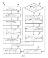
図1には、プリントジョブ中にインクジェットのアレイ内の動作不良のインクジェットを特定するためのプロセス200が示される。このプロセス200は、媒体ロール紙W上で印刷されるインク画像に対応する画像データを生成することから開始する(ブロック204)。プリンタ5では、光学画像形成システム54が、印刷ゾーン20内、及びその下の媒体ロール紙W上で形成されたインク画像から反射された光に対応する画像データを生成する。光学画像形成システム54は、ラスタ化された画像データを生成する。つまり光学画像形成システム54は、媒体ロール紙W上の単一の画素の行に各行を対応させて、一連の画像データの行を生成する。媒体ロール紙Wが、光学画像形成システム54を通過して処理方向Pへ移動すると、光学センサは、連続する画像データの行を生成する。制御装置50は、ラスタ化された画像データ内の一連の画像の行から2次元表示のインク画像を生成する。
FIG. 1 shows a
印刷動作中、カラーモジュール21A〜21Dのうちの1つ以上のインクジェットが動作不良となる恐れがある。本明細書で使用される用語「動作不良のインクジェット」とは、印刷中に期待される動作モードから逸脱するインクジェットのことを指す。動作不良のインクジェットの例として全くインク滴を射出しなくなったもの、途切れ途切れにのみ射出するもの、画像受取部材の不正確な位置にインク滴を射出するものが含まれる。制御装置50は、画像データで動作不良のインクジェットに対応する画像不良を特定する(ブロック208)。ある種類の画像不良は、「光の筋」と呼ばれる。画像受取部材がインクで満たされるべき画像の部分のインクにより覆われないで、そのかわりに目に見えてしまう、処理方向Pに延在する直線部を含む印刷画像の領域で光の筋は発生する。一例として、画像受取部材の上に印刷される濃いインクで覆われた長方形の領域で、この領域を通って処理方向Pに延在する動作不良のインクジェットにより印刷されない細い筋が存在する場合に光の筋が発生する。
During the printing operation, one or more ink jets of the
ある構成では、制御装置50は、プリンタ5を動作させてプリントジョブのインク画像を印刷するために用いられる、印刷画像のデジタルデータに直接アクセスする必要なしに、プリントジョブ中に数回にわたって印刷される画像の印刷領域内の画像不良を特定する。例えば、1つの「プリントジョブでは、単一の4ページの書類を複数コピーすることが含まれる。制御装置50は、プリントジョブ内の1ページ上の長方形のベタ領域等の、プリントジョブにおけるページ内の1つ以上の領域に対応する、予想画像データを特定する。プリントジョブ中、この長方形領域の印刷を担当する、印刷ゾーン20内のインクジェットのうちの1つが動作不良になった場合、画像データ内に光の筋が現れる。別の実施形態では、制御装置50は、インク画像を印刷するために用いるデジタルデータを参照して、画像データ内の不良を特定する。このデジタルデータには、ラスタ化された画像形式の2進値データ、ページ記述言語(PDL)内の印刷命令データ、ASCII(情報交換用米国標準文字)データ、又はその他のプリンタ内のインク画像の形式を制御する、当技術分野で周知の全てのデジタルデータ形式が含まれ得る。
In one configuration, the controller 50 is printed several times during a print job without having to directly access the digital data of the print image that is used to operate the
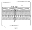
画像不良が特定されると、制御装置50は、画像不良のクロス処理方向の位置を参照して、動作不良の可能性のあるインクジェットの候補を特定する(ブロック212)。特定の状況下では、実際に動作不良のインクジェットは、クロス処理方向の画像不良の位置と対応しないため、このインクジェットをインクジェットの「候補」と呼ぶ。例えば、図3Aでは、プリントヘッド102内のインクジェット116が、動作不良であり、印刷画像は、それに対応する光の筋174を含む。光学画像形成システム54内の光センサ160は、光の筋174を検知し、制御装置50が画像不良を特定する。図3Aでは、光センサ160は、インクジェット116とではなく、インクジェット118と位置を合わせているため、制御装置50は、実際に動作不良のインクジェット116ではなく、インクジェットの候補118を特定する。動作不良のインクジェットの誤特定は、媒体ロール紙Wの縮小、媒体ロール紙Wのクロス処理方向のオフセット、光学画像形成システム54内の光センサの位置ずれ、光学画像形成システム54に関する印刷ゾーン20内の1つ以上のプリントヘッドの位置ずれを含む複数の理由から発生する。
When the image defect is identified, the control device 50 refers to the position of the image defect in the cross processing direction to identify an inkjet candidate that may be malfunctioning (block 212). Under certain circumstances, an actually malfunctioning inkjet does not correspond to an image defect location in the cross-process direction, so this inkjet is referred to as an inkjet “candidate”. For example, in FIG. 3A, the
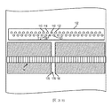
図3Aでは、インクジェットの候補118が、動作不良のインクジェット116からクロス処理方向に1画素の間隔だけオフセットされている。図4Aでは、インクジェットの候補118が、動作不良のインクジェット116から2画素分オフセットされている別の状況が示され、図5Bでは、インクジェットの候補110が、動作不良のインクジェット116から3画素分オフセットされている、さらに別の状況が示される。図4Aでは、光センサ162が、インクジェットの候補124に対応する光の筋184を検知する。図5Aでは、光センサ163が、インクジェットの候補110に対応する光の筋194を検知する。誤差の方向は、クロス処理方向に左又は右のどちらでもよい。本明細書では、インクジェットの候補と、動作不良のインクジェットとの間の誤差が3画素まで示されているが、別のプリンタ構成ではより大きなオフセットも検知、修正する。
In FIG. 3A, the
インクジェットの候補を特定した後、プロセス200により、インクジェットの候補を停止し、周辺のインクジェットを用いて停止したインクジェットの候補分を随意的に補償する(ブロック216)。例えば図3Aでは、制御装置50が、インクジェットの候補118を停止し、インクジェットが動作可能な場合に、プリントジョブがインクジェット118を動作させているときの増加した割合でインクジェット114、116、120、122を動作させることにより、インクジェットの候補118の分を補償しようと試みる。動作不良のインクジェットを停止し、その代わりに、周辺のインクジェットを起動させて、動作不良のインクジェット分のロスを補償する動作を、「インクジェットの代用」動作と呼ぶ。図3Aに示される周辺のインクジェットは、同じプリントヘッド102及び動作不良のインクジェット内であるが、プリンタ5のような交互に配置されたプリントヘッドを用いるインクジェット式プリンタは、1つ以上の交互に配置されるプリントヘッド内の、動作不良のインクジェットにクロス処理方向に近接するインクジェットも代用することができる。別の実施形態では、プリンタ5は、インクジェットの候補を停止するが、プロセス200が実際に動作不良のインクジェットであるインクジェットの候補を特定し終わるまで、周辺のインクジェットを用いた補償を開始しない。停止したインクジェットの候補の分を補償するための周辺のインクジェットの動作を遅らせることで、インクジェットの候補が動作不良のインクジェットでない場合に、インクジェットの候補の停止により生成される光の筋をインク画像がより鮮明に示す。インクジェットの候補が停止したときに周辺のインクジェットを用いて補償することにより、停止したインクジェットの候補が、正しいインクジェットでないときに、生成される画像不良の知覚度は低下する。
After identifying the inkjet candidates, the
正しい動作不良のインクジェットが特定されたとき、周辺のインクジェットの動作により、動作不良のインクジェットにより生成される光の筋の視覚への影響は軽減される、又は取り除かれる。プリンタ5がインクジェットの候補分の補償を開始した後に、プリンタ5はインク画像の印刷を継続し、光学画像形成システム54が印刷されるインク画像に関する付加的な第2の画像データを生成する(ブロック220)。
When a correct malfunctioning inkjet is identified, the peripheral inkjet action reduces or eliminates the visual streak of light generated by the malfunctioning inkjet. After the
いくつかの場合では、プロセス200により、インクジェットの候補を不正確に特定し、不正確に特定されたインクジェットの候補の結果に対して第2の画像不良の分を補償する。制御装置50は、インクジェットの候補に対する補償を行った後に印刷された、追加的なインク画像の画像データにおける、第1の特定された画像不良に近接する第2の画像不良を特定する(ブロック224)。図3A、図4A、図5Aの例では、特定されたインクジェットの候補は、実際には動作可能なインクジェットであり、第1の画像不良を検知した後に、動作不良のインクジェット116は、動作不良として特定されない。その結果として、インクジェットの候補の停止により、動作不良のインクジェット116により生成される画像不良の他に、第2の画像不良が生成されてしまう。例えば図3Bでは、隣接するインクジェット116及び118は、それぞれ動作不良で停止しているため、インクジェットの候補118の停止により、元の光の筋174よりも幅の広い光の筋176が生成される。光の筋176は、元の光の筋174よりも大きな悪影響を画質に及ぼす、より大きな可視の画像不良である。インクジェット114は、追加のインク滴178を射出し、インクジェット120及び122は、追加のインク滴180を射出して、停止したインクジェット分を補償するが、依然として、インクジェットの候補118の誤特定により、より広い光の筋176が生成される。
In some cases, the
図4Bでは、インクジェットの候補120を停止し、インクジェット120分を補償することで、図4Aの元の光の筋184と、第2の光の筋188と、が生成されている。動作可能なインクジェット118は、光の筋188に対して補償しようと試みるが、副産物として、動作可能インクジェット118は、光の筋184に対しても部分的に補償してしまう。インクジェット118は、光の筋184と、光の筋188との間にインク滴186を形成する。動作可能なインクジェット122及び124は、インク滴189で示される停止したインクジェット120分も部分的に補償する。このように、図4Bは、2つの光の筋184及び188が生成される様子を示す。動作不良のインクジェット116の誤特定により、図4Bにおける全体に渡る知覚可能な画質の劣化は、図4Aより依然として大きい、しかし、その知覚可能な劣化は、図3Bに示される組合せの光の筋176よりは小さい。
In FIG. 4B, the
図5Bでは、インクジェットの候補110の動作を停止し、このインクジェット110分を補償することで、図5Aの光の筋194に加えて光の筋198が生成される。図5Bでは、インクジェット106及び108が、インク滴195を生成し、このインク滴195が、光の筋198に対してクロス処理方向の左側から部分的に補償する。インクジェット112及び114は、インク滴196を生成して、クロス処理方向の右側からの光の筋198に対して補償する。インクジェット112及び114はまたインク滴197も生成し、このインク滴197が、左側からの光の筋194の分を部分的に補償する。このように、図5Bには、2つの光の筋194及び198生成されるようすが示されている。動作不良のインクジェット116の誤特定により、図5Bの全体的な画質の劣化は、図5Aよりも大きいが、2つの理由から画質に及ぼす全体的な悪影響は、図3B及び図4Bの悪影響よりも小さい。第1の理由は、図5Bでは停止したインクジェット110は、左側の2つの動作可能なインクジェット106及び108と、右側のインクジェット112及び114により、完全に補償され、第1の光の筋194は、左側のインクジェット112及び114により、部分的に補償される。第2の理由は、2つの光の筋194および198の間のクロス処理方向の距離が、図3B及び図4Bよりも図5Bのほうが長く、これにより、知覚される画質上の2つの光の筋を組み合わせた影響は低減される。
In FIG. 5B, the operation of the
組合せでは、図3A〜図5Aの例、及び図3B〜図5Bの例により、動作不良のインクジェットの周辺の誤特定されたインクジェットを修正することで生成された追加の画像の劣化がそれぞれ示されている。しかし、図3A及び図3Bで示された単一画素の誤差が最も大きな悪影響を画質に及ぼし、図5A及び図5Bにおける3画素の誤差は、最も小さい悪影響を画質に及ぼすため、画像劣化の度合いは、インクジェットの候補と動作不良のインクジェットとの間のオフセット量に反比例する。インクジェットの特定おいて、1画素の誤差の可能性を減らすため、プロセス200のある実施形態では、ブロック212で、インクジェットの候補に適用した、クロス処理方向への所定のオフセット量を含む。例として図3Aを参照すると、制御装置50は、通常光センサ160により検知された光の筋174と位置を合わせるインクジェット118以外のインクジェットの候補を選択する。
In combination, the examples of FIGS. 3A-5A and FIGS. 3B-5B show the degradation of additional images produced by correcting misidentified inkjets around the malfunctioning inkjet, respectively. ing. However, since the single pixel error shown in FIGS. 3A and 3B has the greatest adverse effect on the image quality, and the error of 3 pixels in FIGS. 5A and 5B has the least adverse effect on the image quality, the degree of image degradation. Is inversely proportional to the amount of offset between the inkjet candidate and the malfunctioning inkjet. In order to reduce the possibility of one pixel error in inkjet identification, an embodiment of
図3Aを用いて、所定のオフセットの一例では、インクジェットの候補として、インクジェット118を選択する代わりに、制御装置50は、インクジェット118から所定の数の画素だけクロス処理方向にオフセットされたインクジェットの候補を選択する。例えば、プロセス200では、クロス処理方向に左へ4画素だけオフセットさせて画素118の代わりの画素候補として画素110を選択することが出来る。動作不良のインクジェットの特定において1画素の誤差が一般的なプリンタ構成では、所定のオフセットにより、実際に動作不良のインクジェットに隣接するインクジェットの動作を停止する可能性を低減し、動作不良のインクジェットの誤特定による画質対する悪影響を低減する。下記に示す通り、制御装置50は、前に特定された動作不良のインクジェットのクロス処理方向のオフセット値を随意的にメモリに格納することが出来る。前に特定された動作不良のインクジェットが、新しく特定された光の筋に近接している場合、制御装置50は、メモリに格納された、同じオフセット値を用いて、画像データ内の光の筋のクロス処理方向の位置を参照して、前に特定されたクロス処理方向のオフセットでインクジェットの候補を特定することが出来る。
With reference to FIG. 3A, in one example of the predetermined offset, instead of selecting the
再度図1を参照すると、プロセス200は、第1の画像不良及び第2の画像不良の大きさ及びクロス処理方向の位置を参照して第1の画像不良を生成した実際のインクジェットを特定する(ブロック228)。プロセス200により、不正確なインクジェットの候補が停止されると、第2の画像不良のクロス処理方向の位置により、不正確に特定されたインクジェットの候補と、実際の動作不良のインクジェットとの間のオフセット量に対する情報が提供される。動作不良のインクジェットのクロス処理方向の位置がすぐに特定されなくても、制御装置50は停止したインクジェットの候補の予想されるクロス処理方向の位置の情報を格納している。プロセス200は、画像データ内の第1の画像不良と第2の画像不良との間のオフセット量の大きさ及び方向を参照して、動作不良のインクジェットを特定する。
Referring again to FIG. 1, the
例えば図6Aは、位置Nで検知された光の筋406のほぼ中心の画素位置に対する反射率の値のグラフである。反射率のグラフ404には、正しい動作不良のインクジェット(図3A及び3Bでは、インクジェット116)特定されプリントジョブ中に補償されたときに、予想される相対的な反射率が示される。反射率グラフ410には、プロセス200により画素位置N+1に位置するインクジェットの候補118分が補償される図3Bの構成が示される。反射率グラフ410は、画素位置Nでの最も高い頂点となり、この反射率グラフは、位置N+1でインクジェット118の停止により「膝」のように折れる。グラフ410相対的な大きさ及び位置により、インクジェットの候補118は、動作不良のインクジェット116から、右に1画素ずれて位置することが示される。同様に、グラフ408には、インクジェットの候補(図3Bのインクジェット114)が動作不良のインクジェットから1画素左の画素位置N−1に位置することが示される。グラフ408では、画素Nでの反射率の値は同じグラフ410とほぼ同じであるが、反射率グラフの膝は画素N−1に位置して、停止したインクジェット114を示す。
For example, FIG. 6A is a graph of the reflectance value with respect to the pixel position substantially at the center of the
図6Bには、画素候補が動作不良の画素からクロス処理方向に2画素だけオフセットされたときの、画素位置Nの検知された光の筋406の周りの反射率の値のグラフが示される。グラフ412は、インクジェットの候補(図4Bでは、インクジェット112)が動作不良のインクジェット116からクロス処理方向に2画素だけ左に位置する状況を示す。グラフ412では、位置N−2の反射率の頂点は、停止したインクジェット108により生成される部分的に補償された光の筋を表し、位置Nの光の筋は、画素位置Nでの部分的な補償を表す。グラフ414は、インクジェットの候補(図4Bではインクジェット120)が、動作不良のインクジェット116からクロス処理方向に2画素だけ右に位置する図4Bの状況を示す。グラフ414では、位置N+2の反射率の頂点は、停止したインクジェット120により生成される部分的に補償された光の筋を表し、位置Nでの光の筋は動作不良のインクジェット116の画素位置Nでの部分的な補償を表す。
FIG. 6B shows a graph of reflectance values around the detected
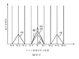
図6Cには、画素候補が動作不良の画素からクロス処理方向に3画素だけオフセットされたときに、画素位置Nで検知された光の筋406の周りの反射率の値のグラフが示される。グラフ416は、インクジェットの候補(図5Bではインクジェット110)が、動作不良のインクジェット116からクロス処理方向に3画素左に位置した状況を示す。グラフ416では、位置N−3での反射率頂点は、停止したインクジェット110によりを生成される完全に補償された光の筋を表し、位置Nの光の筋は、画素位置Nでの部分的な補償を表す。図5Bの実施形態では、動作不良のインクジェットのクロス処理方向の両側の2つの周辺インクジェットを有する動作不良のインクジェットに対して補償するため、位置N−3での反射率の頂点は完全に補償される。これらの周辺インクジェットとは、インクジェットの候補110に対して、106、108、112、114である。グラフ418は、インクジェットの候補(図5Bでは、インクジェット122)が、動作不良のインクジェット116からクロス処理方向に3画素右に位置した図5Bの状況を示す。グラフ418では、位置N+3の反射率頂点は、停止したインクジェット122により生成される、完全に補償された光の筋に対応し、位置Nでの光の筋は、動作不良のインクジェット116の画素位置Nでの部分的な補償を表す。
FIG. 6C shows a graph of the reflectance values around the
図6A〜図6Cに示す、上記のそれぞれの不正確なインクジェットの候補に対する停止及び補償は、反射率データの特定可能なセットを生成する。再度図1を参照すると、プロセスブロック228では、制御装置50は、元の画像不良と新しい画像不良との反射率の値を参照して、動作不良のインクジェットを特定する。ある実施形態では、制御装置50は、図6A〜図6Cに示される反射率の値グラフに対応するデータ等の、動作不良のインクジェットを不正確に特定可能な範囲に関する反射率の値に対応する所定のデータをメモリから検索する。制御装置50は、新しい画像不良を含む追加の画像データと、最も密接に対応する所定の反射率の値とを特定し、元の画像不良と新しい画像不良との組合せを参照して、動作不良のインクジェットを特定する。
Stopping and compensation for each of the above incorrect inkjet candidates, shown in FIGS. 6A-6C, produces an identifiable set of reflectance data. Referring again to FIG. 1, at
第2の画像データを参照して、動作不良のインクジェットを特定した後、 制御装置50は、前に停止したインクジェットの候補を再起動させ、インクジェットの候補の周辺のインクジェットを通常モードの動作に戻す(ブロック232)。制御装置は、新しく特定された動作不良のインクジェットの候補も停止させ、動作不良のインクジェットの周りの周辺のインクジェットを起動させることにより動作不良のインクジェットの候補の分を補償する(ブロック236)。 After identifying the malfunctioning inkjet with reference to the second image data, the control device 50 restarts the previously stopped inkjet candidates and returns the inkjets around the inkjet candidates to normal mode operation. (Block 232). The controller also stops newly identified malfunctioning inkjet candidates and compensates for the malfunctioning inkjet candidates by activating peripheral inkjets around the malfunctioning inkjet (block 236).
別の構成では、インクジェットの候補により生成される単一の追加の画像不良を参照して、動作不良のインクジェットを特定する代わりに、プロセス200を繰り返す方法で動作不良のインクジェットを特定する。この繰り返す構成では、プロセス200は、新しいインクジェットの候補を選択した後(ブロック236)、追加の画像データを生成する(ブロック220)。プロセス200は、インクジェットの候補が動作不良のインクジェットであり、画像データが第2の画像不良を含まなくなるまで、あるいはプロセス200が、インクジェットの候補により生成される、連続した光の筋と、動作不良のインクジェットにより生成される元の光の筋との間のオフセット量を特定するまで、新しいインクジェットの候補の選択が続けられる(ブロック224)。別の構成では、図3A及び図3Bに示す通り、動作不良のインクジェットの予想される範囲からの最小オフセットを用いてインクジェットの候補を選択して、動作不良のインクジェットに隣接するインクジェットの候補が選択される可能性を最小にすることが出来る。例えば、元の光の筋の特定された位置から、クロス処理方向に、[−10,−4]の範囲で左のインクジェットの位置、及び[4,10]の範囲で右のインクジェットの位置のインクジェットを介してプロセス200は行われる。別の構成では、制御装置50は、元の画像不良と動作不良のインクジェットの周りの異なるインクジェットを停止することにより現れる光の筋との間の複数のクロス処理方向の距離を参照して、動作不良のインクジェットを特定する。さらに別の構成では、ブロック216にプロセスの間、インクジェットの候補は、部分的にのみ停止する。部分的な停止及び周辺のインクジェットによる修正は、光の筋等の検知可能なアーチファクトを印刷画像内に生成できるよう選択される。この操作により、印刷画像の劣化の少ない所望の機能が提供される。
In another configuration, instead of identifying a malfunctioning inkjet with reference to a single additional image defect generated by the inkjet candidate, the malfunctioning inkjet is identified in a manner that repeats the
プロセス200では、動作不良のインクジェットが誤特定されている状況に対応しているが、多くの場合、プロセスブロック212で特定されたインクジェットの候補は、実際の動作不良のインクジェットである。図6A〜図6Cの反射率グラフ404で示される通り、動作不良のインクジェットが正しく特定されると、光の筋の大きさは小さくなる。動作不良のインクジェットが正しく特定された場合、追加の画像データは、第2の画像不良を含まず(ブロック224)、動作不良のインクジェットの周辺のインクジェットは、動作不良のインクジェット分の補償を継続する(ブロック240)。
動作不良のインクジェットを特定した後、プロセス200では、クロス処理方向の元のインクジェットの候補と動作不良のインクジェットとの間のオフセット量を随意的に格納することが出来る(ブロック244)。プリンタ5では、制御装置50は、オフセットの値をメモリに格納する。最初に特定されたインクジェットの候補が動作不良のインクジェットである状況では、オフセットの値はゼロであり、ある実施形態では、このオフセット値は正の値又は負の値を有して、このオフセットがクロス処理方向に相対的に左方向か右方向かを示す。前に特定された動作不良のインクジェットに、クロス処理方向で近接する別の動作不良のインクジェットの位置を特定する精度を向上させるために、メモリ内に格納されたオフセット値を用いることが出来る。動作不良のインクジェットの見かけの位置と実際に位置との間のオフセット値は、媒体ロール紙Wの幅に渡る媒体ロール紙の縮小の異なる度合い、及び光学画像形成システム54の位置合せの変化量を含む、様々な要因のため、印刷ゾーン20の幅に渡って変動する。結果として、制御装置50は、印刷ゾーンの異なる領域で特定された動作不良のインクジェットに対応する格納されたオフセット値にアクセスし、同じ領域で別のインクジェットが動作不良になった場合、前に特定されたオフセット値を用いて、より迅速に動作不良のインクジェットを特定することが出来る。さらに、既知のインクジェットを停止させ、インクジェットの停止により生成される光の筋又はその他の画像アーチファクトの位置を検知することのより、領域内で動作不良のインクジェットの無い行中の処理の中で、インクジェットの位置を特定することが出来る。この情報を用いて、後に別のインクジェットが動作不良になったときに、その位置を示すことが出来る。
After identifying the malfunctioning inkjet, the
上記の通り、プロセス200では、プリントジョブ中にインクジェットを選択的に停止し、また周辺のインクジェットを操作して動作不良のインクジェット分を補償する。プロセス200では、また停止したインクジェットの候補が実際には動作不良のインクジェットでないときを特定し、次いで実際に動作不良のインクジェットを特定する。ある実施形態では、プロセス200は、インクジェットの候補を完全に停止し、周辺のインクジェットを起動させて、停止したインクジェット分を2進法、即ちオン/オフの方法で補償する。2進法で起動と停止とを行うことにより、動作不良のインクジェット分を迅速に補償するが、プロセス200が動作不良のインクジェットを誤特定したときに、不正確なインクジェットを停止させることにより、第2の画像不良が発生してしまう。図2には、インクジェットの候補を徐々に停止させ、周辺のインクジェットを徐々に起動させ、インクジェットを僅かに補償するプロセス300が示される。以下の議論では、機能又は動作を行うプロセスとは、制御装置がメモリ内に格納された、プログラムされた命令を実行して、プリンタの1つ以上の構成部品を操作して、機能又は動作を行うことを指す。プロセス300を上記のプロセス200に組み込むことが出来る。説明のためにプリンタ5及び制御装置50を参照して、プロセス300を説明する。
As described above, in
プロセス300は、第1の減少率でインクジェットの候補を動作させ、(ブロック304)、第1の増加率で周辺のインクジェット動作させる(ブロック308)ことから開始する。プリンタ5では、制御装置50が媒体ロール紙W上にインク画像を形成するための印刷ゾーン20内のインクジェットに対する発射信号を生成する。プロセス300のある構成では、制御装置5は、インクジェットの候補に対して通常生成されるであろう、発射信号の90%分だけを生成し、周辺のインクジェットに対して10%分多い発射信号を生成して、インクジェットの候補分を補償する。制御装置50は、周辺のインクジェットに対する発射信号の増加した時間を決めて、インクジェットの候補に対して、発射信号が生成されていない時間に対応させる。プロセス300では、部分的に停止するインクジェットの候補及び部分的に補償する周辺のインクジェットを用いて、少なくとも1つのインク画像を印刷する、同様に、いくつかの構成では、複数のインク画像を印刷する(ブロック312)。
プロセス300は、増加的に継続するが、インクジェットの候補は部分的に起動して動作し、周辺のインクジェットは、インクジェットの候補分を部分的に補償する(ブロック316)。プロセス300は、インクジェットの候補の動作率を下げ(ブロック320)、周辺のインクジェットの動作率を増加させて(ブロック324)、増加的に継続する。インクジェットの候補及び周辺のインクジェットをそれぞれ調整した後、プリンタ5は、少なくとも1つの追加のインク画像を印刷する(ブロック312)。所定の回数を繰り返した後、インクジェットの候補を完全に停止させ、周辺のインクジェットを完全に起動させる(ブロック316)。次いで、プリンタ5は、インクジェットの候補を完全に停止させ、周辺のインクジェットに、この停止したインクジェットの分を完全に補償させて、動作を継続する(ブロック328)。プロセス300において、インクジェットの候補を徐々に停止させることにより、印刷画像内の画像不良が裸眼で確認できる程大きくなる前に、光学センサシステム54を用いて印刷したインク画像内の第2の画像不良を、制御装置50が特定することが出来る。
プリンタ5で、プロセス200と連動してプロセス300を行われるとき、インクジェットの候補が動作不良のインクジェットではないと特定されれば、プロセス200により、いつでもプロセス300を中断させるよう制御装置50を構成する。ある実施形態では、制御装置50は、プロセス300の、それぞれの繰り返しの後に、生成された画像データから、数字の信頼性スコアを生成する。本明細書で使用される用語「信頼性スコア」とは、インクジェットの候補が実際に動作不良のインクジェットであるかという推定に基づいて、生成される数字の値のことを指す。例えば、光学センサにより検知された光の筋の輝度を信頼性スコアの測定値として用いることが出来る。インクジェットを停止することにより、停止前の輝度より弱い輝度の光の筋が生じた場合、信頼性スコアはより高い値となる。あるいは、インクジェットを停止することにより、停止前の輝度より強い光の筋の輝度を有する光の筋が生じた場合、信頼性スコアはより低い値となる。
When the
一構成では、信頼性スコアを0%から100%までのパーセントの値として表すことが出来る。プロセス300により、インクジェットの候補を徐々に停止させ、周辺のインクジェットの補償を徐々に増加させて補償するため、インクジェットの動作の調整により、一般に信頼性スコアはより高い値、又はより低い値に変動する。例えば、インクジェットの候補も動作不良のインクジェットの場合、周辺のインクジェットが動作不良のインクジェットの分を補償するため、信頼性スコアは100%へ増加する。インクジェットの候補が動作不良のインクジェットでない場合、動作可能なインクジェットを停止することにより次第に大きな影響を画質に及ぼす、別の画像不良が生じるため信頼性スコアは0%へ減少する。
In one configuration, the reliability score can be expressed as a percentage value from 0% to 100%. The
プリンタ5では、インクジェットの候補を完全に停止させて画質への影響を低減させる前に、信頼値が所定の閾値より下に落ちた場合、プロセス300を中断させるよう制御装置50を構成する。いくつかの実施形態では、制御装置50は、インクジェットの候補が完全に停止させていなくても、信頼値が高い方の閾値を超えた場合、インクジェットの候補が動作不良のインクジェットであることを特定する。制御装置50は、プロセス300を中断させ、インクジェットの候補を完全に停止させ、周辺のインクジェットを用いて、インクジェットの候補を完全に補償する。したがって、プロセス300を中断して、インクジェットの候補が動作不良のインクジェットでないとき、画質に対する影響を低減することが出来、インクジェットの候補が動作不良のインクジェットのとき、動作不良のインクジェット分をより迅速に補償することが出来る。
In the
Claims (5)
前記クロス処理方向に前記画像受取面に渡って構成された複数の光検知器であって、複数の光検知器のうちのそれぞれが、前記画像受取面から反射した光を検知するよう構成された複数の光検知器と、
前記複数のインクジェット及び前記複数の光検知器に操作可能に接続された制御装置であって、
第1の複数の発射信号を生成して、前記複数のインクジェットから前記画像受取面の上にインクを射出して第1の印刷画像を形成し、
前記複数の光検知器を用いて、前記第1の印刷画像に対応する画像データを生成し、
前記画像データを参照して、前記第1の印刷画像内の第1の不良を特定し、
前記画像データ内の前記第1の不良のクロス処理方向の位置を参照して、前記第1の不良を生成したインクジェットの候補を特定し、
前記クロス処理方向の前記インクジェットの候補の動作を停止して、前記複数のインクジェットから前記画像受取面の上にインクを射出して第2の印刷画像を形成し、
前記複数の光検知器を用いて、前記第2の印刷画像に対応する画像データを生成し、
前記第1の不良の前記クロス処理方向の位置のうちの所定の距離以内に位置する前記第2の印刷画像の前記画像データ内で特定された第2の不良の第2のクロス処理方向の位置に応じて、前記インクジェットの候補以外の前記複数のインクジェットのうちの第2のインクジェットが、前記第1の不良を生成したことを特定し、
前記第2のインクジェットの特定に応じて、前記インクジェットの候補に対する発射信号を修正しない方法で生成し、
前記第2のインクジェットの動作を停止して、前記複数のインクジェットから前記画像受取面の上にインクを射出して、第3の印刷画像を形成するように構成される制御装置と、を含むインクジェット式印刷装置。 A plurality of inkjets arranged across the print zone in the cross-process direction, each configured to eject ink droplets on the image receiving surface that passes through the plurality of inkjets and moves in the process direction With inkjet
A plurality of light detectors configured across the image receiving surface in the cross processing direction, each of the plurality of light detectors configured to detect light reflected from the image receiving surface. Multiple light detectors;
A control device operably connected to the plurality of inkjets and the plurality of photodetectors,
Generating a first plurality of firing signals to eject ink from the plurality of inkjets onto the image receiving surface to form a first printed image;
Using the plurality of photodetectors to generate image data corresponding to the first print image;
Referring to the image data to identify a first defect in the first print image;
Referring to the position of the first defect in the image data in the cross processing direction, the inkjet candidate that generated the first defect is identified,
Stopping the operation of the inkjet candidates in the cross-process direction, and ejecting ink onto the image receiving surface from the plurality of inkjets to form a second printed image;
Using the plurality of photodetectors to generate image data corresponding to the second print image;
The position of the second defect in the second cross process direction specified in the image data of the second print image located within a predetermined distance among the positions of the first defect in the cross process direction. In response, a second inkjet of the plurality of inkjets other than the inkjet candidate has generated the first defect,
In response to the identification of the second inkjet, a firing signal for the inkjet candidate is generated in a non-correcting manner,
A controller configured to stop the operation of the second ink jet and to eject ink from the plurality of ink jets onto the image receiving surface to form a third printed image. Printer.
前記クロス処理方向の前記インクジェットの候補に近接する前記複数のインクジェットのうちの他の少なくとも1つのインクジェットに関する発射信号の生成を修正して、前記第2の印刷画像を形成するようさらに構成される、請求項1に記載のインクジェット式印刷装置。 The control device is
Further configured to modify firing signal generation for at least one other inkjet of the plurality of inkjets proximate to the inkjet candidate in the cross-process direction to form the second printed image; The ink jet printing apparatus according to claim 1.
前記インクジェットの候補に対して、減少した数の発射信号を生成して、前記第2の印刷画像を形成し、
前記クロス処理方向で前記インクジェットの候補に近接する少なくとも1つのインクジェットに対して、増加した数の発射信号を生成して、前記第2の印刷画像を形成し、
前記第2の印刷画像の画像データを参照して、前記インクジェットの候補が前記第1の不良を生成する信頼度に対応するスコアを生成し、
所定の閾値より低い前記信頼度に対応するスコアに応じて、前記第1の印刷画像内の前記第1の不良を生成した、前記インクジェットの候補以外の前記複数のインクジェットのうちの前記第2のインクジェットを特定するようさらに構成される、請求項2に記載のインクジェット式印刷装置。 The control device is
Generating a reduced number of firing signals for the inkjet candidates to form the second printed image;
Generating an increased number of firing signals for at least one inkjet in proximity to the inkjet candidate in the cross-process direction to form the second printed image;
With reference to the image data of the second print image, a score corresponding to the reliability with which the inkjet candidate generates the first defect is generated,
The second of the plurality of inkjets other than the inkjet candidates that generated the first defect in the first print image according to a score corresponding to the reliability lower than a predetermined threshold. The inkjet printing apparatus of claim 2, further configured to identify an inkjet.
前記複数の光検知器を用いて、前記第3の印刷画像に対応する画像データを生成し、
前記第1の不良の前記クロス処理方向の位置と、前記第2の不良の前記第2のクロス処理方向の位置とのうちの少なくとも1方の前記所定のクロス処理方向の距離以内に位置する、前記第3の印刷画像の前記画像データ内で特定された、第3の不良の第3のクロス処理方向の位置に応じて、前記インクジェットの候補及び前記第2のインクジェット以外の前記複数のインクジェットのうちの第3のインクジェットが、前記第1の不良を生成したことを特定するようさらに構成される、請求項3に記載のインクジェット式印刷装置。 The control device is
Using the plurality of photodetectors to generate image data corresponding to the third print image;
Located within a distance in the predetermined cross process direction of at least one of the position of the first defect in the cross process direction and the position of the second defect in the second cross process direction; According to the position of the third defective third cross process direction specified in the image data of the third print image, the plurality of inkjets other than the inkjet candidate and the second inkjet. The inkjet printing apparatus of claim 3, further configured to identify that a third inkjet of them has generated the first defect.
The control device identifies the second inkjet adjacent to the inkjet candidate in the cross process direction according to a size of the second defect larger than the size of the first defect. 2. An ink jet printing apparatus according to 1.
Applications Claiming Priority (2)
| Application Number | Priority Date | Filing Date | Title |
|---|---|---|---|
| US13/407,437 | 2012-02-28 | ||
| US13/407,437 US8646862B2 (en) | 2012-02-28 | 2012-02-28 | System and method for detection and compensation of inoperable inkjets in an inkjet printing apparatus |
Publications (3)
| Publication Number | Publication Date |
|---|---|
| JP2013176987A JP2013176987A (en) | 2013-09-09 |
| JP2013176987A5 JP2013176987A5 (en) | 2016-03-24 |
| JP6000157B2 true JP6000157B2 (en) | 2016-09-28 |
Family
ID=48950962
Family Applications (1)
| Application Number | Title | Priority Date | Filing Date |
|---|---|---|---|
| JP2013023982A Active JP6000157B2 (en) | 2012-02-28 | 2013-02-12 | System and method for detecting and compensating for malfunctioning inkjet in an inkjet printing apparatus |
Country Status (3)
| Country | Link |
|---|---|
| US (1) | US8646862B2 (en) |
| JP (1) | JP6000157B2 (en) |
| DE (1) | DE102013202418A1 (en) |
Families Citing this family (8)
| Publication number | Priority date | Publication date | Assignee | Title |
|---|---|---|---|---|
| WO2015117925A1 (en) * | 2014-02-06 | 2015-08-13 | Oce-Technologies B.V. | Ink jet printing method and printer |
| EP3053748A1 (en) | 2015-01-29 | 2016-08-10 | OCE-Technologies B.V. | Method for compensating failing nozzles |
| US10562318B2 (en) | 2017-11-03 | 2020-02-18 | Landa Corporation Ltd. | Method and system for compensating for a malfunctioning nozzle |
| US10507647B1 (en) | 2018-01-02 | 2019-12-17 | Landa Corporation Ltd. | Methods and systems for compensating for a malfunctioning nozzle in a digital printing system |
| WO2020159499A1 (en) * | 2019-01-30 | 2020-08-06 | Hewlett-Packard Development Company, L.P. | Color variation mitigation for inter-pen error hiding |
| JP7194659B2 (en) * | 2019-09-20 | 2022-12-22 | 芝浦メカトロニクス株式会社 | Solution coating device and tablet printing device |
| JP2023129792A (en) * | 2022-03-07 | 2023-09-20 | 株式会社Screenホールディングス | Printing system and defective nozzle detecting method |
| US11912045B2 (en) * | 2022-03-24 | 2024-02-27 | Xerox Corporation | System and method for printing color images on substrates in an inkjet printer |
Family Cites Families (30)
| Publication number | Priority date | Publication date | Assignee | Title |
|---|---|---|---|---|
| JP2723992B2 (en) | 1989-09-08 | 1998-03-09 | 株式会社日立製作所 | Thermal transfer printer |
| US6572213B2 (en) | 2001-10-31 | 2003-06-03 | Hewlett-Packard Development Company, L.P. | System and method for detecting invisible ink drops |
| US20040027618A1 (en) | 2002-06-03 | 2004-02-12 | Fuji Photo Film Co., Ltd. | Image defect detecting method |
| US7039348B2 (en) | 2002-12-17 | 2006-05-02 | Xerox Corporation | Method for maintaining image on image and image on paper registration |
| US6695435B1 (en) | 2003-05-30 | 2004-02-24 | Xerox Corporation | Selective replacement for artifact reduction |
| JP2005059402A (en) * | 2003-08-12 | 2005-03-10 | Canon Finetech Inc | Inkjet recorder |
| US7424169B2 (en) | 2003-08-15 | 2008-09-09 | Xerox Corporation | Active compensation of streaks using spatial filtering and feedback control |
| JP2005144695A (en) * | 2003-11-11 | 2005-06-09 | Sony Corp | Head unit, droplet ejector, information processor, method for providing notification of information on state, method for updating information on state, method for detecting bad position, and program |
| JP4622400B2 (en) * | 2004-09-08 | 2011-02-02 | 富士ゼロックス株式会社 | Image recording device |
| US7382507B2 (en) | 2004-11-17 | 2008-06-03 | Xerox Corporation | Image quality defect detection from image quality database |
| US7427118B2 (en) | 2004-11-30 | 2008-09-23 | Xerox Corporation | Systems and methods for detecting intermittent, weak and missing jets with an inline linear array sensor |
| US7338144B2 (en) * | 2005-09-29 | 2008-03-04 | Xerox Corporation | Ink jet printer having print head with partial nozzle redundancy |
| US7455387B2 (en) | 2005-09-30 | 2008-11-25 | James Matthew Cunnington | Printhead with waste ink drip bib |
| US7690746B2 (en) | 2008-03-21 | 2010-04-06 | Xerox Corporation | Systems and methods for detecting print head defects in printing clear ink |
| US9390352B2 (en) | 2008-04-22 | 2016-07-12 | Hewlett-Packard Development Company, L.P. | Concurrent image and diagnostic pattern printing |
| US7905567B2 (en) | 2008-05-16 | 2011-03-15 | Avago Technologies Ecbu Ip (Singapore) Pte. Ltd. | Closed-loop printing registration systems, devices, components and methods |
| JP2010000685A (en) * | 2008-06-20 | 2010-01-07 | Seiko Epson Corp | Liquid jetting apparatus, and liquid jetting method |
| US8660373B2 (en) | 2008-07-22 | 2014-02-25 | Xerox Corporation | PDF de-chunking and object classification |
| US8208183B2 (en) | 2008-11-19 | 2012-06-26 | Xerox Corporation | Detecting image quality defects by measuring images printed on image bearing surfaces of printing devices |
| US7857414B2 (en) | 2008-11-20 | 2010-12-28 | Xerox Corporation | Printhead registration correction system and method for use with direct marking continuous web printers |
| US8368955B2 (en) | 2008-12-15 | 2013-02-05 | Xerox Corporation | Method for assessing synchronized print defects |
| JP5531416B2 (en) * | 2009-02-02 | 2014-06-25 | セイコーエプソン株式会社 | Printing apparatus and printing inspection method |
| US8599434B2 (en) | 2009-02-24 | 2013-12-03 | Xerox Corporation | Method and system for improved solid area and heavy shadow uniformity in printed documents |
| US8136913B2 (en) | 2009-03-20 | 2012-03-20 | Xerox Corporation | System and method for measuring drop position in an image of a test pattern on an image substrate |
| US8162433B2 (en) | 2009-03-30 | 2012-04-24 | Xerox Corporation | System and method for scheduling ink jet recovery in an ink jet printer |
| US8162431B2 (en) | 2009-04-07 | 2012-04-24 | Xerox Corporation | System and method for detecting weak and missing ink jets in an ink jet printer |
| JP2011079171A (en) * | 2009-10-05 | 2011-04-21 | Fujifilm Corp | Image processing method, image processing device, and image forming apparatus |
| JP2011098546A (en) * | 2009-11-09 | 2011-05-19 | Olympus Corp | Image recorder and control method of image recorder |
| JP5725597B2 (en) * | 2010-03-19 | 2015-05-27 | 富士フイルム株式会社 | Fine pattern position detection method and apparatus, defective nozzle detection method and apparatus, and liquid ejection method and apparatus |
| US20110242187A1 (en) * | 2010-04-06 | 2011-10-06 | Xerox Corporation | Test Pattern Effective For Fine Registration Of Inkjet Printheads And Method Of Analysis Of Image Data Corresponding To The Test Pattern In An Inkjet Printer |
-
2012
- 2012-02-28 US US13/407,437 patent/US8646862B2/en active Active
-
2013
- 2013-02-12 JP JP2013023982A patent/JP6000157B2/en active Active
- 2013-02-14 DE DE102013202418A patent/DE102013202418A1/en not_active Ceased
Also Published As
| Publication number | Publication date |
|---|---|
| DE102013202418A1 (en) | 2013-08-29 |
| JP2013176987A (en) | 2013-09-09 |
| US8646862B2 (en) | 2014-02-11 |
| US20130222455A1 (en) | 2013-08-29 |
Similar Documents
| Publication | Publication Date | Title |
|---|---|---|
| JP6000157B2 (en) | System and method for detecting and compensating for malfunctioning inkjet in an inkjet printing apparatus | |
| US8605303B2 (en) | Content-aware image quality defect detection in printed documents | |
| JP5869441B2 (en) | Method and system for aligning a print head that ejects clear ink in an inkjet printer | |
| US8845060B2 (en) | Printing apparatus and processing method thereof | |
| US9259920B2 (en) | Printing device and printing method | |
| US8840223B2 (en) | Compensation for alignment errors in an optical sensor | |
| US8223351B2 (en) | Method and system for continuous feed printing systems | |
| US8585173B2 (en) | Test pattern less perceptible to human observation and method of analysis of image data corresponding to the test pattern in an inkjet printer | |
| US20110242187A1 (en) | Test Pattern Effective For Fine Registration Of Inkjet Printheads And Method Of Analysis Of Image Data Corresponding To The Test Pattern In An Inkjet Printer | |
| US9844961B1 (en) | System and method for analysis of low-contrast ink test patterns in inkjet printers | |
| US8814305B2 (en) | System and method for full-bleed and near full-bleed printing | |
| JP2004338402A (en) | Hard copy device and method | |
| EP3219496B1 (en) | System and method for compensating for malfunctioning inkjets | |
| US9375962B1 (en) | System and method for identification of marks in printed test patterns | |
| US9434155B1 (en) | Method and system for printhead alignment based on print medium width | |
| US20150077454A1 (en) | System and method of printhead calibration with reduced number of active inkjets | |
| US8882236B1 (en) | System and method for compensating for defective inkjets ejecting black ink in solid fill areas | |
| US8767246B2 (en) | System and method for page alignment in a printer | |
| US9305248B2 (en) | Test pattern data, non-transitory computer readable medium, and test pattern | |
| US8155549B2 (en) | Duplex electrophotographic printing using sacrificial sheets | |
| US8894179B1 (en) | System and method for high speed inoperative inkjet compensation | |
| US9096071B2 (en) | Dot detection method and color image reproduction apparatus | |
| JP6095582B2 (en) | System and method for ink jet process direction alignment in printer operation using a high speed image receiving surface | |
| US11475258B1 (en) | Time and printed image history dependent TRC | |
| JP2023040724A (en) | Recording device, recording method and program |
Legal Events
| Date | Code | Title | Description |
|---|---|---|---|
| A521 | Request for written amendment filed |
Free format text: JAPANESE INTERMEDIATE CODE: A523 Effective date: 20160208 |
|
| A621 | Written request for application examination |
Free format text: JAPANESE INTERMEDIATE CODE: A621 Effective date: 20160208 |
|
| A871 | Explanation of circumstances concerning accelerated examination |
Free format text: JAPANESE INTERMEDIATE CODE: A871 Effective date: 20160208 |
|
| A975 | Report on accelerated examination |
Free format text: JAPANESE INTERMEDIATE CODE: A971005 Effective date: 20160308 |
|
| A131 | Notification of reasons for refusal |
Free format text: JAPANESE INTERMEDIATE CODE: A131 Effective date: 20160315 |
|
| A521 | Request for written amendment filed |
Free format text: JAPANESE INTERMEDIATE CODE: A523 Effective date: 20160603 |
|
| TRDD | Decision of grant or rejection written | ||
| A01 | Written decision to grant a patent or to grant a registration (utility model) |
Free format text: JAPANESE INTERMEDIATE CODE: A01 Effective date: 20160809 |
|
| A61 | First payment of annual fees (during grant procedure) |
Free format text: JAPANESE INTERMEDIATE CODE: A61 Effective date: 20160830 |
|
| R150 | Certificate of patent or registration of utility model |
Ref document number: 6000157 Country of ref document: JP Free format text: JAPANESE INTERMEDIATE CODE: R150 |
|
| R250 | Receipt of annual fees |
Free format text: JAPANESE INTERMEDIATE CODE: R250 |
|
| R250 | Receipt of annual fees |
Free format text: JAPANESE INTERMEDIATE CODE: R250 |
|
| R250 | Receipt of annual fees |
Free format text: JAPANESE INTERMEDIATE CODE: R250 |
|
| R250 | Receipt of annual fees |
Free format text: JAPANESE INTERMEDIATE CODE: R250 |