JP6000079B2 - Transfer apparatus and transfer method - Google Patents
Transfer apparatus and transfer method Download PDFInfo
- Publication number
- JP6000079B2 JP6000079B2 JP2012247704A JP2012247704A JP6000079B2 JP 6000079 B2 JP6000079 B2 JP 6000079B2 JP 2012247704 A JP2012247704 A JP 2012247704A JP 2012247704 A JP2012247704 A JP 2012247704A JP 6000079 B2 JP6000079 B2 JP 6000079B2
- Authority
- JP
- Japan
- Prior art keywords
- transfer
- card
- recording medium
- preheating
- roller
- Prior art date
- Legal status (The legal status is an assumption and is not a legal conclusion. Google has not performed a legal analysis and makes no representation as to the accuracy of the status listed.)
- Active
Links
Images


Classifications
-
- B—PERFORMING OPERATIONS; TRANSPORTING
- B41—PRINTING; LINING MACHINES; TYPEWRITERS; STAMPS
- B41F—PRINTING MACHINES OR PRESSES
- B41F16/00—Transfer printing apparatus
- B41F16/0006—Transfer printing apparatus for printing from an inked or preprinted foil or band
-
- B—PERFORMING OPERATIONS; TRANSPORTING
- B41—PRINTING; LINING MACHINES; TYPEWRITERS; STAMPS
- B41J—TYPEWRITERS; SELECTIVE PRINTING MECHANISMS, i.e. MECHANISMS PRINTING OTHERWISE THAN FROM A FORME; CORRECTION OF TYPOGRAPHICAL ERRORS
- B41J2/00—Typewriters or selective printing mechanisms characterised by the printing or marking process for which they are designed
- B41J2/315—Typewriters or selective printing mechanisms characterised by the printing or marking process for which they are designed characterised by selective application of heat to a heat sensitive printing or impression-transfer material
- B41J2/32—Typewriters or selective printing mechanisms characterised by the printing or marking process for which they are designed characterised by selective application of heat to a heat sensitive printing or impression-transfer material using thermal heads
- B41J2/325—Typewriters or selective printing mechanisms characterised by the printing or marking process for which they are designed characterised by selective application of heat to a heat sensitive printing or impression-transfer material using thermal heads by selective transfer of ink from ink carrier, e.g. from ink ribbon or sheet
-
- B—PERFORMING OPERATIONS; TRANSPORTING
- B41—PRINTING; LINING MACHINES; TYPEWRITERS; STAMPS
- B41F—PRINTING MACHINES OR PRESSES
- B41F16/00—Transfer printing apparatus
- B41F16/0006—Transfer printing apparatus for printing from an inked or preprinted foil or band
- B41F16/002—Presses of the rotary type
- B41F16/0026—Presses of the rotary type with means for applying print under heat and pressure, e.g. using heat activable adhesive
-
- B—PERFORMING OPERATIONS; TRANSPORTING
- B41—PRINTING; LINING MACHINES; TYPEWRITERS; STAMPS
- B41F—PRINTING MACHINES OR PRESSES
- B41F16/00—Transfer printing apparatus
- B41F16/0006—Transfer printing apparatus for printing from an inked or preprinted foil or band
- B41F16/006—Arrangements for moving, supporting or positioning the printing foil or band
-
- B—PERFORMING OPERATIONS; TRANSPORTING
- B41—PRINTING; LINING MACHINES; TYPEWRITERS; STAMPS
- B41J—TYPEWRITERS; SELECTIVE PRINTING MECHANISMS, i.e. MECHANISMS PRINTING OTHERWISE THAN FROM A FORME; CORRECTION OF TYPOGRAPHICAL ERRORS
- B41J2/00—Typewriters or selective printing mechanisms characterised by the printing or marking process for which they are designed
- B41J2/005—Typewriters or selective printing mechanisms characterised by the printing or marking process for which they are designed characterised by bringing liquid or particles selectively into contact with a printing material
- B41J2/0057—Typewriters or selective printing mechanisms characterised by the printing or marking process for which they are designed characterised by bringing liquid or particles selectively into contact with a printing material where an intermediate transfer member receives the ink before transferring it on the printing material
Description
本発明はカードなどの記録媒体に転写フィルム上の画像を転写する転写装置に係わり、画像形成部で画像転写した転写フィルムを記録媒体から剥離する転写フィルム剥離機構の改良に関する。 The present invention relates to a transfer device that transfers an image on a transfer film to a recording medium such as a card, and relates to an improvement of a transfer film peeling mechanism that peels the transfer film on which an image has been transferred by an image forming unit from the recording medium.
一般にこの種の装置は、プラスチックカードなどの媒体上に顔写真、文字情報などの画像を形成する装置として広く知られている。この場合、記録媒体に直接画像を形成する装置構成と、転写フィルムに画像を形成し、この画像を記録媒体に転写する装置構成が知られている。 In general, this type of apparatus is widely known as an apparatus for forming an image such as a facial photograph or character information on a medium such as a plastic card. In this case, an apparatus configuration for directly forming an image on a recording medium and an apparatus configuration for forming an image on a transfer film and transferring the image to a recording medium are known.
後者の装置構成の場合、転写フィルムに形成された画像を記録媒体に転写した後、記録媒体から転写フィルムを剥離する必要がある。このとき、転写フィルムの種類によっては、転写フィルムが温かい状態で記録媒体から剥離しないと転写不良が発生するおそれがある。その際、記録媒体が冷えていると転写フィルムの熱を下げてしまい、転写不良が発生してしまうため、転写処理の前に記録媒体をプレヒートする必要がある。 In the case of the latter apparatus configuration, after the image formed on the transfer film is transferred to the recording medium, it is necessary to peel the transfer film from the recording medium. At this time, depending on the type of transfer film, transfer failure may occur if the transfer film is not peeled off from the recording medium in a warm state. At that time, if the recording medium is cooled, the heat of the transfer film is lowered and transfer defects occur. Therefore, it is necessary to preheat the recording medium before the transfer process.
例えば特許文献1には、インクリボンを用いて記録紙に文字や画像を形成する熱転写プリンタ(ダイレクトプリンタ)において、印字部の上流側に記録紙を加熱するプレヒート機構が設けられている構成が開示されている。この構成によれば、記録紙をプレヒートすることで、サーマルヘッドやインクリボンの長寿命化と熱効率の向上の効果を得ることが出来ると記載されている。 For example, Patent Document 1 discloses a configuration in which a thermal transfer printer (direct printer) that forms characters and images on recording paper using an ink ribbon is provided with a preheating mechanism that heats the recording paper upstream of the printing unit. Has been. According to this configuration, it is described that the effect of extending the life of the thermal head and the ink ribbon and improving the thermal efficiency can be obtained by preheating the recording paper.
また、特許文献2には、中間転写プリンタにおいて、加熱ロールにカバー部材が設けられており、転写処理以外はカバー部材が加熱ロールをカバーしている構成が開示されている。この構成によれば、加熱ロール近傍に常に存在する染着シート(中間転写フィルム)が熱によって変形しないため、画像品質の低下が防止でき、また、染着シートの交換時に高熱に加熱された加熱ロールが露出することがなく安全性の高い装置となるという効果を得ることが出来ると記載されている。 Patent Document 2 discloses a configuration in which a cover member is provided on the heating roll in the intermediate transfer printer, and the cover member covers the heating roll except for the transfer process. According to this configuration, since the dyed sheet (intermediate transfer film) that always exists in the vicinity of the heating roll is not deformed by heat, deterioration of image quality can be prevented, and heating heated to a high temperature when the dyed sheet is replaced It is described that it is possible to obtain an effect that the roll is not exposed and the device is highly safe.
特許文献1の構成では、印字部の加熱部材(サーマルヘッド)とは別に記録媒体のプレヒートのためのプレヒート機構が設けられているため、別途熱源が必要になり、コストアップにつながる。また、特許文献2の構成では、加熱ロールにカバーを設けており、転写処理以外はカバーで覆われているため、仮に加熱ロールで記録媒体にプレヒートを行おうとしてもプレヒートをすることができない。また、加熱ロールでプレヒートを行う場合、加熱ロールと記録媒体の間に染着シートが存在するため、このままプレヒートを行うと染着シートの一部分が熱によるダメージを過剰に受けてしまう。 In the configuration of Patent Document 1, since a preheating mechanism for preheating the recording medium is provided separately from the heating member (thermal head) of the printing unit, a separate heat source is required, leading to an increase in cost. Moreover, in the structure of patent document 2, since the cover is provided in the heating roll and it covers with the cover except transfer processing, even if it preheats a recording medium with a heating roll, it cannot preheat. Further, when preheating is performed with a heating roll, a dyed sheet exists between the heating roll and the recording medium. Therefore, if preheating is performed as it is, a part of the dyed sheet is excessively damaged by heat.
上記課題を達成するため本発明は、転写フィルムを介して加熱部材と転写プラテンとを圧接して転写フィルムに形成された画像を記録媒体に転写する転写装置において、加熱部材と転写プラテンとを有し、加熱部材と転写プラテンとが圧接した作動位置と、加熱部材と転写プラテンとが離間した退避位置との間で移動可能に構成された画像転写部と、転写フィルムを画像転写部に搬送する転写フィルム搬送手段と、記録媒体を画像転写部に搬送する記録媒体搬送手段と、画像転写部と転写フィルム搬送手段と記録媒体搬送手段とを制御する制御手段と、を備え、制御手段は、画像転写部による転写処理の前に、退避位置における加熱部材と転写プラテンとの間のプレヒート位置に記録媒体を搬送して、この加熱部材の熱により記録媒体を温めるプレヒート処理を行い、このプレヒート処理中に転写フィルムを搬送して位置移動させることを特徴とする。
In order to achieve the above object, the present invention provides a transfer apparatus for transferring an image formed on a transfer film by pressing a heating member and a transfer platen through a transfer film to a recording medium. and, conveying a working position where the heating member and the transfer platen is pressed, the movably arranged image transfer portion between the heating member and the transfer platen and is spaced retracted position, the transcription film to the image transfer section A transfer film conveying means, a recording medium conveying means for conveying the recording medium to the image transfer section, and a control means for controlling the image transfer section , the transfer film conveying means, and the recording medium conveying means. Prior to the transfer process by the image transfer unit, the recording medium is transported to a preheat position between the heating member and the transfer platen at the retracted position, and the recording medium is heated by the heat of the heating member. Perform preheating process, characterized in that to position moved by conveying the transfer film during the preheating process.
また、本発明の転写方法は、加熱部材と転写プラテンとで構成される画像転写部で、転写フィルムを介して加熱部材と転写プラテンとを圧接して転写フィルムに形成された画像を記録媒体に転写する転写方法において、加熱部材と転写プラテンとが離間した状態で、記録媒体を加熱部材と転写プラテンとの間のプレヒート位置に搬送する記録媒体搬送ステップと、加熱部材の熱によって転写フィルムを介して記録媒体を温めるプレヒートステップと、プレヒートステップ後に転写フィルムと記録媒体とを転写開始位置に頭出しする頭出しステップと、加熱部材と転写プラテンとを圧接して転写フィルムに形成された画像を記録媒体に転写する画像転写ステップと、を含み、プレヒートステップにおいて、転写フィルムを位置移動させることを特徴とする。 Further, the transfer method of the present invention is an image transfer portion composed of a heating member and a transfer platen, and an image formed on the transfer film by pressing the heating member and the transfer platen through the transfer film is used as a recording medium. In the transfer method for transferring, a recording medium transport step for transporting the recording medium to a preheat position between the heating member and the transfer platen in a state where the heating member and the transfer platen are separated from each other, and the heat of the heating member through the transfer film. A preheating step for warming the recording medium, a cueing step for cueing the transfer film and the recording medium to the transfer start position after the preheating step, and an image formed on the transfer film by pressing the heating member and the transfer platen. An image transfer step for transferring to a medium, and moving the transfer film in the preheating step. And butterflies.
本発明は、転写処理に用いる加熱部材(転写ローラ)の熱を利用して記録媒体(カード)に対して転写処理前のプレヒート処理を行うため、別途プレヒートのための加熱部材を設ける必要がなく、コストが安い。それと同時に、プレヒート時に転写フィルムを位置移動するため、転写フィルムの一部分のみが一定時間以上加熱部材に晒さないため、転写フィルムに対してのダメージが少ない。 In the present invention, since the preheating process before the transfer process is performed on the recording medium (card) using the heat of the heating member (transfer roller) used for the transfer process, there is no need to separately provide a heating member for the preheating. The cost is cheap. At the same time, since the transfer film is moved during preheating, only a part of the transfer film is not exposed to the heating member for a certain period of time, so the damage to the transfer film is small.
よって、安価な構成で記録媒体に対してプレヒート処理を行うことができ、転写不良を抑え、さらに転写フィルムへのダメージも少ないという効果もある。 Therefore, the preheating process can be performed on the recording medium with an inexpensive configuration, and there is an effect that transfer failure is suppressed and damage to the transfer film is small.
以下図示の好適な実施の形態に基づいて本発明を詳述する。図1は本発明に係わる情報記録装置の全体構成の説明図である。図1の装置は各種証明用のIDカード、商取引用のクレジットカードなどに画像情報を記録する。このため情報記録部Aと画像記録部(画像形成部;以下同様)Bと、これらにカードを供給するカード供給部Cが備えられている。 The present invention will be described in detail below based on the preferred embodiments shown in the drawings. FIG. 1 is an explanatory diagram of the overall configuration of an information recording apparatus according to the present invention. The apparatus of FIG. 1 records image information on an ID card for various certifications, a credit card for commercial transactions, and the like. For this purpose, an information recording unit A, an image recording unit (image forming unit; the same applies hereinafter) B, and a card supply unit C for supplying cards to these are provided.
[カード供給部]
装置ハウジング1にはカード供給部Cが設けられ、複数枚のカードを収納するカードカセットで構成されている。図1に示すカードカセット3は複数のカードを立位姿勢で整列して収納し、同図左端から右端にカードを繰り出す。そしてカードカセット3の先端には分離開口7が設けられ、ピックアップローラ19で最前列のカードから装置内に供給する。
[Card supply section]
The device housing 1 is provided with a card supply unit C, and is constituted by a card cassette that stores a plurality of cards. The
[情報記録部の構成]
上述のカードカセット3から送られたカードK(記録媒体;以下同様)は搬入ローラ22から反転ユニットFに送られる。反転ユニットFは装置フレーム(不図示)に旋回動可能に軸受け支持されたユニットフレームと、このフレームに支持された一対、或いは複数のローラ対で構成される。
[Configuration of information recording section]
The card K (recording medium; the same applies hereinafter) sent from the
図示のものは距離を隔てて前後に配置された2つのローラ対20、21をユニットフレームに回転自在に軸支持されている。そしてユニットフレームは旋回モータ(パルスモータなど)で所定角度方向に旋回動し、これに取付けられているローラ対は搬送モータで正逆転方向に回転するように構成されている。この駆動機構は図示しないが、1つのパルスモータでユニットフレームの旋回動と、ローラ対の回転をクラッチで切り換えるように構成しても、ユニットフレームの旋回動とローラ対の回転を別駆動に構成してもよい。
In the illustrated example, two
従ってカードカセット3に準備されたカードはピックアップローラ19と分離ローラ(アイドルコロ)9で1枚ずつ分離され下流側の反転ユニットFに送られる。そして反転ユニットFはカードをローラ対20、21でユニット内に搬入し、ローラ対でニップした状態で所定角度方向に姿勢変更することとなる。
Accordingly, the cards prepared in the
上記反転ユニットFの旋回方向外周には、磁気記録ユニット24と、非接触式IC記録ユニット23及び接触式IC記録ユニット27と、リジェクトスタッカ25が配置されている。尚図示28はバーコードリーダであり、例えば後述する画像形成部Bで印刷したバーコードを読み取って正誤判別(エラー判別)するためのユニットである。以下これらの記録ユニットをデータ記録ユニットという。
A
そこで反転ユニットFで所定の角度方向に姿勢変更されたカードをローラ対20、21で記録ユニットに移送すると、カードに磁気的若しくは電気的にデータ入力することが可能となる。またこれらのデータ入力ユニットで記録ミスが生じた場合にはリジェクトスタッカ25に搬出する。
Therefore, when the card whose posture is changed in the predetermined angle direction by the reversing unit F is transferred to the recording unit by the roller pairs 20 and 21, data can be magnetically or electrically input to the card. Further, when a recording error occurs in these data input units, they are carried out to the
上記反転ユニットFの下流側には画像形成部Bが設けられ、この画像形成部Bにカードカセット3からカードを移送する搬入経路P1が設けられ、この経路P1に前述の反転ユニットFが配置されている。また、搬入経路P1にはカードを搬送する搬送ローラ(ベルトでも良い)29、30が配置され、図示しない搬送モータ(ステッピングモータ)に連結されている。この搬送ローラ29、30は正逆転切り換え可能に構成され、反転ユニットFから画像形成部Bにカードを搬送するのと同様に画像形成部Bからカードを反転ユニットFに搬送するようになっている。
An image forming unit B is provided on the downstream side of the reversing unit F, and a carry-in path P1 for transferring a card from the
上記画像形成部Bの下流側には収容スタッカ55にカードを移送する搬出経路P2が設けられている。搬出経路P2にはカードを搬送する搬送ローラ(ベルトでも良い)37、38が配置され、図示しない搬送モータに連結されている。
On the downstream side of the image forming unit B, a carry-out path P2 for transferring the card to the
尚、搬送ローラ37と搬送ローラ38の間にはデカール機構36が配置され、搬送ローラ37、38間に保持されたカード中央部を押圧することによってカール矯正する。このためデカール機構36は図示しない昇降機構(カムなど)で図1上下方向に位置移動可能に構成されている。
A
[画像形成部]
画像形成部Bは、カードの表裏面に顔写真、文字データなど画像を形成する。この画像形成部Bには転写プラテン31が設けられ、このプラテン上でカード表面に画像形成を行う。図示の装置は、転写フィルム46(中間転写フィルム)上に画像形成し、このフィルムの画像を転写プラテン31上でカード面に転写する。このため装置ハウジング1には、インクリボンカセット42と転写フィルムカセット50が装備される。
[Image forming unit]
The image forming unit B forms an image such as a face photograph or character data on the front and back surfaces of the card. The image forming portion B is provided with a
図示のインクリボンカセット42は、昇華型インクリボンその他の熱転写インクリボン41を操出ロール43と巻取ロール44間に巻装し、装置ハウジング1に着脱可能に装着される。この巻取ロール44には図示しないワインドモータMr1が連結されている。また、装置側にはサーマルヘッド40と画像形成プラテン45がインクリボン41を挟んで対向配置されている。
The illustrated ink ribbon cassette 42 has a sublimation ink ribbon or other thermal
上記サーマルヘッド40にはヘッドコントロール用IC74a(図11参照)が連結され、サーマルヘッド40を熱制御するようになっている。このヘッドコントロール用IC74aは画像データに従ってサーマルヘッド40を加熱制御することによってインクリボン41を後述する転写フィルム46に画像形成する。このためサーマルヘッド40の熱制御と同期して巻取ロール44が回転し、インクリボン41を所定速度で巻き取るように構成されている。図示f1はサーマルヘッド40を冷やす為の冷却ファンである。
A
一方、転写フィルムカセット50(以下「フィルムカセット」という)も装置ハウジング1に着脱可能に装着される。このフィルムカセット50に装填された転写フィルム46がプラテンローラ(画像形成プラテン)45とインクリボン41の間を走行して転写フィルム上に画像を形成する。このため転写フィルム46は供給スプール47と巻取スプール48に巻回され、この転写フィルム46は画像形成プラテン45上で形成された画像を転写プラテン31と後述する転写ローラ33の間に移送する。図示49は転写フィルム46の移送ローラであり、この移送ローラの周面にピンチローラ32aと32bが配置され、図示しない駆動モータに連結されている。また、供給スプール47は図示しないDCモータMr2に連結されており、巻取スプール48も同様に図示しないDCモータに連結されている。
On the other hand, a transfer film cassette 50 (hereinafter referred to as “film cassette”) is also detachably attached to the apparatus housing 1. The
また、図示34aは転写プラテン31に転写フィルム46を案内するガイドコロであり、図示34bは転写プラテン31を記録媒体から剥離する剥離コロ(剥離部材;以下同様)である。このガイドコロ34aと剥離コロ34bは転写プラテン31を挟んでガイドコロ34aが上流側に、剥離コロ34bが下流側に、それぞれフィルムカセット50に取付けられている。そして、転写処理時のカード搬送方向に対して剥離コロの下流側直後にはカードの転写面側を支持する支持ピン51(支持部材;以下同様)が設けられている。この支持ピン51は剥離ピン34bを支持するブラケット69に設けられており、剥離ピン34bと支持ピン51は一定の位置関係を保持している。また、ガイドコロ34aと剥離コロ34bとの間隔L1はカードKの画像形成方向(搬送方向)長さLcより短く(L1<Lc)設定されている。
34a is a guide roller for guiding the
上記転写プラテン31には、転写フィルム46を挟んで転写ローラ33が対向配置されている。この転写ローラ33は転写フィルム46上に形成された画像をカードに加熱圧接して転写する。このため転写ローラ33はヒートローラで構成され、フィルムカセット50の内側から転写プラテン31に圧接・離間するように後述する転写部材昇降手段61が備えられている。尚図示Se1はインクリボン41の位置検出センサであり、図示Se2は転写フィルム46の有無検出センサであり、画像形成部Bには装置内に発生した熱を外に出す為のファンf2が設けられている。このように、サーマルヘッド40を用いて中間転写フィルム46に画像を形成するユニットを1次転写部、転写ローラ33を用いて、1次転写部で中間転写フィルム46に形成した画像をカードKに転写するユニットを2次転写部という。
A
上記画像形成部Bの下流側にはカード収容部Dが設けられ、転写プラテン31から送られたカードを収容スタッカ55に収容する。この収容スタッカ55は昇降機構56と図示しないレベルセンサで、カード収容量に応じて繰り下げ降下するように構成されている。
A card accommodating portion D is provided on the downstream side of the image forming portion B, and the card sent from the
[フィルムカセットの構成]
上述の転写フィルム46を装填するフィルムカセット50について説明する。このフィルムカセット50は図2に示すように装置ハウジング1とは分離したユニットで構成され、装置ハウジング1に着脱可能に取付けられている。図示しないが図1前面側にフロントカバーが開閉自在に配置され、このフロントカバーを開けた状態で装置フレームにフィルムカセット50を図2矢印方向に装着するようになっている。
[Structure of film cassette]
The
このフィルムカセット50には、供給スプール47と巻取スプール48が着脱可能に装着される。図示52はスプールの一端を支持する軸受部であり、図示56はスプールの他端側を支持するカップリング部材である。このカセット側に配置された軸受部52とカップリング部材56でスプール端部を支持している。そして供給スプール47から剥離コロ34b、を経てガイドコロ34a、35b、35a、次いで巻取スプール48に転写フィルム46が架け渡される。
A
なお、上記ガイドコロ35a、35b、34a及び剥離コロ34b(剥離部材;以下同様)は、図示のものはフィルムカセット50に取付けたピン部材(従動コロ)で構成してあるが、これは固定ピン(不回転)であっても良い。本装置では、カードに転写フィルム46上の画像を転写する際は供給スプール47で転写フィルム46を巻き取りながら転写を行う。よって、剥離コロ34bは転写フィルム46の転写時におけるフィルム搬送方向下流側(転写ローラ33よりも供給スプール47側)に設けられている。
The
剥離コロ34bはブラケット69に固定されており、そのブラケット69には支持ピン51が設けられている。転写フィルム46は剥離コロ34bと支持ピン51との間を走行するため、転写フィルム46を交換する際はフィルムカセット50を装置ハウジング1から抜き取った状態で、支持ピン51は剥離コロ34bから離間するように構成されている。
The peeling
図3に示すように、支持ピンの一端51aはブラケット69に着脱可能に嵌合されており、他端51bはブラケット69の凹部に枢支されているため、支持ピン51は破線矢印方向に回動可能に構成されている。よって、支持ピン51はセット位置(実線)と開放位置(破線)に(ピボット)移動可能であり、ユーザはフィルムカセット50を装置ハウジング1から抜き取り、支持ピン51を開放位置に移動させた状態で転写フィルム46を交換し、支持ピン51をセット位置に戻してからフィルムカセット50を装置ハウジング1に装填する。
As shown in FIG. 3, since one end 51a of the support pin is detachably fitted to the
なお、支持ピン51はセット位置の状態で剥離コロ34bと一定の位置関係を保持する必要がある。図4(a)に示すように、カードKから転写フィルム46が剥離された後にカード先端が支持ピン51に支持された状態では、支持ピン51に対して剥離後の転写フィルム46の走行方向(図の下方)に力が加わる。支持ピン51を支持するブラケット69の軸受け凹部は転写フィルム46の走行方向に沿った方向に設けられており、支持ピン51はセット位置において軸受け凹部の底面に支持されるため、カードKから転写フィルム46走行方向の力が加わっても、ブラケット69は支持ピン51をしっかりと支持することができる。当然、転写フィルム走行方向と交わる方向に支持ピン51が回動移動してもよいが、支持ピン51がカードKを支持したときに剥離コロ34bとの位置関係が変わらないようセット位置を保持する必要がある。
The
このように架け渡された転写フィルム46には装置側に配置された移送ローラ49とピンチローラ32a、32bが係合される。そして供給スプール47と巻取スプール48に連結される駆動回転軸(不図示)と、上記移送ローラ49は同一速度でフィルムを走行するように駆動回転する。
A
ここで、2次転写部の詳細な構成を図4に従って説明する。2次転写部には、転写ローラ(ヒートローラ)33、転写プラテン31、転写フィルム46をガイドするガイドコロ34a、同様に転写フィルム46をガイドして、カードKから転写フィルム46を剥離する剥離コロ34bと剥離コロ34bの下流でカードKの転写面側を支持する支持ピン51が配置されている。また、転写ローラ33と転写プラテン31との間にカードKを搬送する搬送ローラ30と支持ピン51を通過したカードをニップして下流側へ搬送する搬送ローラ37が設けられている。なお、搬送ローラ30と搬送ローラ37との間の距離は、転写処理以外の通常搬送時にカード搬送ができるよう、カードKの搬送方向の長さLcよりも短い距離に設定されている。
Here, a detailed configuration of the secondary transfer unit will be described with reference to FIG. In the secondary transfer portion, a transfer roller (heat roller) 33, a
転写ローラ33と剥離コロ34b及び支持ピン51とはそれぞれ図4(a)に示す作動位置と図(b)に示す退避位置に移動可能に構成されている。剥離コロ34bは作動位置において、搬送経路P1に沿って搬送されるカードKの表面に対して転写フィルム46を介して接するように設定されている。よって、図5に示すように、剥離コロ34bのカード接触点は、転写ローラ33の作動位置におけるカード接触点と、搬送ローラ37がカード転写面と接触するカード接触点を結ぶ直線Ln1(転写ローラ33のカード接触点と搬送ローラ37のカード接触点とを通る第1接線)よりも、少なくとも転写プラテン31側(カード側)にオフセットしており、直線Ln1よりも転写ローラ33側に配置されることはない。なお、本実施形態では、剥離コロ34bのカード接触点は直線Ln1よりも1.52mm転写プラテン側にオフセットしている。なお、剥離コロ34bのカード接触点が直線Ln1よりも転写ローラ33側でなければよく、直線Ln1の線上に設定してもよい。
The
よって、カードに転写された転写フィルム46は、転写ローラ33から剥離コロ34bまではカードに接着しており、カードが剥離コロ34bに到達したときに転写フィルム46がカード表面から剥離される。なお、剥離された転写フィルム46はカードと直交する方向(図の下方向)に巻き取られるため、カードと剥離後の転写フィルム46は剥離コロ34bを介して略90度の関係が保たれる(剥離角度βが略90度)。
Therefore, the
例えば、図18の示したように剥離コロ34bが搬送経路P1から(転写ローラ33側にオフセットして)離れた位置に設けられていた場合、転写されたフィルム46が剥離コロ34bに到達する前にカードから剥離してしまう。このような構成では転写フィルム46がカードから剥離する位置と剥離角度(β2)が不確定となり、転写不良が発生するおそれがある。さらに転写されてから剥離するまでの時間が変化してしまうため、良好な剥離を行えない場合がある。よって、剥離コロ34bを本実施形態の作動位置に設定することで、剥離角度と、剥離するまでの時間(転写ローラ33から剥離位置までの距離)が一定となるため、転写不良の発生を抑えることができる。
For example, as shown in FIG. 18, when the peeling
剥離コロ34bを通過したカードは、図4(a)に示すようにカード先端が転写フィルム46の走行方向に引っ張られて下方に姿勢が変化することなく、支持ピン51に支持される。この支持ピン51のカード接触点は転写ローラ33の作動位置におけるカード接触点と、剥離コロ34bの作動位置におけるカード接触点を結ぶ直線Ln2(転写ローラ33のカード接触点と剥離コロ34bのカード接触点とを通る第2接線)よりも、転写プラテン31側(カード側)にオフセットしており、直線Ln2よりも転写ローラ33側に配置されることはない。なお、本実施形態では、支持ピン51のカード接触点は直線Ln2よりも0.35mm転写プラテン側にオフセットしている。なお、支持ピン51のカード接触点は直線Ln2よりも転写ローラ33側でなければよく、直線Ln2の線上に設定してもよい。
The card that has passed through the peeling
支持ピン51のカード接触点が直線Ln2よりも下方に配置されると、従来のようにカード先端が転写フィルム46の走行方向に引っ張られてしまうため、少なくとも支持ピン51のカード接触点は直線Ln2上か、直線Ln2よりも転写プラテン31側に配置する必要がある。しかし、あまりにも転写プラテン31側にオフセットし過ぎると、支持ピン51と剥離コロ34bとの間の段差が大きくなってしまい、剥離コロ34bがカードKから離れてしまうため、転写フィルム46の剥離位置が不安定になる問題が生じるおそれがあるため、扱う記録媒体の種類等から適宜設定することが望ましい。
If the card contact point of the
さらに、剥離コロ34bから支持ピン51までの距離が大きいと、カード先端が支持されない状態が長くなってしまうため、剥離コロ34bの直後に支持ピン51を配置することが望ましい。よって、本実施形態では、剥離コロ34bの直径が5mm、支持ピン51の直径が3mm、剥離コロ34bの中心と支持ピン51の中心との間の距離が5mmとしているため、剥離コロ34bと支持ピン51との間の隙間は1mmである。これにより、支持ピン51を剥離コロ34bよりも細くすることで、支持ピン51を剥離コロ34bに近づけることができる。しかし、細くしすぎるとカードKを支持する強度が保てないため、ある程度の強度は残しておいた上で支持ピン51を細くすることが望ましい。
Furthermore, if the distance from the peeling
また、前述の通り、剥離コロ34bと支持ピン51は同一部材のブラケット69に支持されているため、剥離コロ34bと支持ピン51との高さ関係の位置決めが容易である。例えば、支持ピン51を装置本体側に設けてもよいが、その場合、装置本体側の支持ピン51とフィルムカセット50側の剥離コロ34bをそれぞれ作動位置と退避位置に移動する必要があり、さらに双方が作動位置において上述の配置関係を維持しなければならないため、高い部品加工精度が必要になる。
Further, as described above, since the peeling
なお、支持ピン51によってカード先端が若干持ち上げられるため、支持ピン51より下流の搬送ローラ37が離れた位置に配置されていると、カード先端が搬送ローラ37にニップされなくなってしまう。よって、カード先端が上側の搬送ローラ37の下半分領域(図4(a)の搬送ローラ37の斜線部)に入る位置に搬送ローラ37を配置している。
Since the card tip is slightly lifted by the
また、転写プラテン31に対して転写ローラ33を圧接及び離間させる。後述する制御手段70は、カード上に画像転写するときには転写ローラ33を作動位置(Pn1)に移動して圧接し、画像形成後(カード後端が転写ローラ33を通過した後)は退避位置(Pn2)に移動して離間させる。これによって、カード後端が転写ローラ33を通過した後に転写ローラ(ヒートローラ)33に転写フィルム46が接触して、転写フィルム46が転写ローラ33の熱により変形するのを防止する。
Further, the
また、制御手段70は、カード後端が支持ピン51を通過するタイミングで、剥離コロ34b及び支持ピン51を作動位置(Pn3)から退避位置(Pn4)に移動させる。ここで、剥離コロ34b及び支持ピン51を退避位置に移動させているため、両面印刷を行う際に、搬送パス上流側の反転ユニットFに向けてカードをスイッチバック搬送させた時にカードが支持ピン51や剥離コロ34bに衝突することを防止している。このような制御によって転写フィルムに過剰の熱が作用して変形する恐れも、また転写フィルム46を剥離する際に転写不良が発生することもない。
Further, the control means 70 moves the peeling
そこで転写ローラ33と剥離コロ34及び支持ピン51を昇降させるために、後述する転写部材昇降手段61と、剥離部材昇降手段62(移動手段)を制御手段で制御する。この制御は、カード先端が転写プラテン31に到達する見込み時間で転写ローラ33を退避位置(Pn2)から作動位置(Pn1)に位置移動する。また、これと前後して(例えばプリントコマンド信号、上流側のジョブ終了信号など)剥離コロ34b及び支持ピン51を退避位置(Pn4)から作動位置(Pn3)に移動する。
Therefore, in order to raise and lower the
この状態でプラテン位置に所定速度で移動するカードに、その先端から後端に画像を転写する。カード後端が転写ローラ33を通過した見込み時間で転写ローラ33を退避位置(Pn2)に移動させる。すると転写フィルム46はガイドコロ34aと剥離コロ34bに支持され、その一部はカード表面に打擲した状態となる。そしてカードが排出方向に移動するのに伴って転写フィルム46はカード表面から徐々に剥離される。その際、カード先端は支持ピン51に支持される。
In this state, an image is transferred from the leading edge to the trailing edge of the card that moves to the platen position at a predetermined speed. The
この画像転写の過程で転写フィルルム46はカード表面と一定の剥離角度βでカード先端から後端まで同一角度方向にフィルムを引き剥がすこととなる。従ってカードに転写された画像に斑が生ずることがない。
In the image transfer process, the
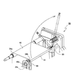
次に上述の転写部材昇降手段61と、剥離部材昇降手段62の構成について説明する。図6は前述のフィルムカセット50と、転写部材昇降手段61と、剥離部材昇降手段62の全体構成を示す説明図である。この昇降手段61、62と転写ローラ33は装置フレームに取り付けられている。一方、剥離コロ34bと支持ピン51はフィルムカセット50側に取付けられている。
Next, the configuration of the transfer member lifting / lowering means 61 and the peeling member lifting / lowering means 62 will be described. FIG. 6 is an explanatory view showing the overall configuration of the above-described
図6において、フィルムカセット50は装置フレームに同図矢印方向に着脱可能に装着される。そして装置フレームに設けられている転写部材昇降手段61、剥離部材昇降手段62、転写ローラ33と、フィルムカセット50の転写フィルム46とが組み合わせられる。図7は、転写部材昇降手段61、剥離部材昇降手段62及び転写ローラ33の組み立て分解図であり、転写部材昇降手段61には転写ローラ33を備えた昇降フレーム63が図示矢印方向に昇降可能に支持されている。また、剥離コロ34b及び支持ピン51を保持するブラケット69の嵌合部69Sはフィルムカセット50側に嵌合溝50Sで昇降可能に支持されている(図2参照)。取付けられている。
In FIG. 6, a
上記転写ローラ33を備えた昇降フレーム63の構成を図8に示す。転写ローラ33は転写プラテン(図示のものはローラ)31と対向する位置に昇降フレーム63と共に図8矢印方向に昇降するようにユニットフレーム64に取り付けられている。そしてユニットフレーム64にシフトモータMSが取付けられ、このモータの回転軸にシフトカム64c(例えば偏心カム;不図示)が設けられている。このシフトカム64cの回転でこのカムと長溝(カムフォロアー;不図示)で嵌合している昇降フレーム63は図8上下方向に昇降する。
FIG. 8 shows a configuration of the lifting
また、転写ローラ33には、転写プラテン31と対向する位置に開閉カバー65a、65b(合わせて開閉カバー65)が支軸65p1、65p2を中心に図示矢印方向に回転(開閉)するように設けてある。この開閉カバー65は高熱の転写ローラ33に使用者の手指が触れないようにガードする。このため転写ローラ33が退避位置(Pn2)のときには開閉カバー65はローラ表面を覆い、カードがジャムを起こして使用者がジャム解除作業を行う際にローラ表面に触れるのをガードし、転写ローラ33が作動位置(Pn1)のときにはローラ表面から退避して転写フィルム46をプラテン31に圧接する。
Further, the
その開閉機構は、ユニットフレーム64にラック63rが一体に設けてあり、昇降フレーム63にこのラックと噛合するピニオン63pが設けてある。このピニオン63pは開閉カバー65の支軸65p1と65p2に歯車結合されている。従ってシフトモータMSでシフトカム64cを回転して昇降フレーム63を図8矢印方向に上昇させると、開閉カバー65a、65bがそれぞれ図示矢印方向に回転する。
In the opening / closing mechanism, a
以上の説明から明らかなように転写ローラ33をカードに圧接した作動位置(Pn1)と離間した退避位置(Pn2)との間で昇降する転写部材昇降手段61は、シフトモータMSとシフトカム64cで構成されることとなる。またこの転写部材昇降手段61で転写ローラ33の開閉カバー65を開位置(図3(a))と閉位置(図3(b))との間で開閉している。
As is apparent from the above description, the transfer member elevating means 61 that elevates between the operating position (Pn1) where the
また、前記記録媒体Kに画像転写した転写フィルム46を剥離する作動位置(Pn3)と記録媒体Kから離間した退避位置(Pn4)との間で剥離部材34bを昇降する剥離部材昇降手段62について説明する。図8(b)は図7の機構から剥離部材昇降手段62の構成のみを抽出した説明図であり、この図8(b)に示すようにシフトモータMSに歯車連結された駆動回転軸64dにはドライブカム66cが連結されている。このドライブカム66cと係合するカムフォロア66fを備えたレバー66rが図8上下方向に昇降するようにスリットとピンでユニットフレーム64に昇降可能に支持されている。このレバー66rには復帰スプリング66Sがユニットフレーム64との間に架け渡してある。
Further, the peeling member raising / lowering means 62 for raising and lowering the peeling
従ってシフトモータMSの回転でドライブカム66cが回転すると、カムフォロア66fを有するレバー66rが上下動することとなる。尚ドライブカム66cは後述するようにシフトモータMSの角度制御で、剥離部材34bを退避位置(Pn4)に待機させ、この状態から作動位置(Pn3)に移動する。
Therefore, when the
そこでドライブカム66cを回転させてレバー66rを矢印方向に上昇させる。このレバー66rには揺動レバー67が連結され、この揺動レバー67は支軸67pを中心に図8矢印方向に回転(揺動)する。するとこの揺動レバー67にピン−スリット連結された昇降レバー68aが矢印方向に下降する。この昇降レバー68aと一体の作動レバー68bが、剥離ピンブラケット69a、69bと係合している。なお、上記昇降レバー68aはユニットフレーム64に上下動方向にピンースリット結合によって運動規制されている。
Therefore, the
従ってレバー66rがドライブカム66cで上昇し、復帰スプリング66Sで下降する上下動運動で揺動レバー67が揺動し、昇降レバー68aと作動レバー68bが上下動し、この作動レバー68bと係合する剥離ピンブラケット69a、69bが上下動する。この剥離ピンブラケット69a、69bは剥離コロ(剥離部材)34bの両端部に一体的に取り付けられている。
Accordingly, the
以上の説明から明らかなように、剥離部材昇降手段62は、シフトモータMSとドライブカム66cとレバー66r、揺動レバー67、昇降レバー68a、作動レバー68bで構成されている。図示の装置は剥離コロ(剥離部材)34bを、その両端部を作動レバー68bで偏ることなく同一量ずつ均等に昇降することを特徴としている。
As is clear from the above description, the peeling member lifting / lowering means 62 includes the shift motor MS, the
次に上述したシフトカム64cとドライブカム66cと駆動回転軸64dとの関係を図10のカム線図で説明する。シフトモータMSに歯車連結された駆動回転軸64dにシフトカム64cとドライブカム66cが連結されている。この両カムは例えば次のようなカム面で構成する。ホームポジションHPで両カムは転写ローラ33を「down」、剥離コロ34を「down」位置にそれぞれ退避位置に移動する。この状態から駆動回転軸64dを例えば180度回転する。このときシフトカム64cとドライブカム66cは転写ローラ33を「up」、剥離コロ34を「up」位置にそれぞれ作動位置に移動する。
Next, the relationship among the
更に駆動回転軸64dを180度位置から角度θ1回転すると、シフトカム64cは転写ローラ33を「down」位置に移動し、ドライブカム66cは、剥離コロ34を「up」位置に維持する。そして駆動回転軸64dを角度θ2回転すると、シフトカム64cは転写ローラ33を「down」位置に保持し、剥離コロ34を「down」位置に維持する。なおこのようなカム構成は、図示のカム形状に拘わらず偏心カムその他、種々のカム形状が採用可能である。
When the
なお、本実施形態では、転写フィルム46は熱間剥離タイプのフィルムを使用している。熱間剥離タイプのフィルムの特性としては、カードに転写フィルムを転写した後に転写フィルムが温かい内に剥離をすると綺麗にカードから剥離することができる。このとき、転写フィルムの温度が下がってしまうと転写フィルムの剥離層が綺麗に剥れずに、転写面が白く霞んでしまう白化現象が発生し、転写不良となってしまう。また、ある程度温かくても剥離後のカードの挙動(姿勢)が安定しないと転写フィルムの剥離位置が安定せずに、白化現象が起こり同様に転写不良となってしまう。しかし、転写フィルムが過度に温かい状態で剥離をすると、カードの挙動に関係なく白化現象は起こらないが、転写フィルムの剥離層が通常よりも剥れやすくなるため、カード端縁よりも外側で転写フィルムが剥れることによる剥離カスが発生してしまい、カード端縁部の美観を損ねてしまう。
In this embodiment, the
よって、上述した支持ピン51によって剥離後のカードKの姿勢は安定することで白化による転写不良を抑えることができる。しかし、カード先端が支持ピン51から搬送ローラ37に到達するまでの間は、カード先端の姿勢が不安定となってしまうため、カード先端のみ白化による転写不良が生じる場合がある。カード先端部が搬送ローラ37にニップされてしまえば、カード全体の姿勢は安定するため、カード先端部以降では転写不良は発生し難い。
Accordingly, the post-peeling posture of the card K is stabilized by the support pins 51 described above, so that transfer failure due to whitening can be suppressed. However, until the end of the card reaches the conveying
そこで、本実施形態では、カード先端部(支持ピン51と搬送ローラ37との間の距離に相当する部分)を転写前にプレヒートすることで、カード先端部の白化を抑えている。そのため、退避位置における転写ローラ33を覆う開閉カバー65には図9に示すように開口65cが設けられており、カード先端を転写ローラ33と転写プラテン31との間(プレヒート位置)に位置づけることにより転写ローラ33の熱をカード先端に伝えることができる。
Therefore, in the present embodiment, whitening of the card front end portion is suppressed by preheating the card front end portion (the portion corresponding to the distance between the
転写ローラ33の熱によってカード先端をプレヒートする際は、転写フィルム46を介して行われるため、転写フィルム46の一部が過剰に温められると、温められた部分だけが剥離しやすくなり剥離カスが発生するおそれがある。また、カード先端のプレヒートを独立した工程で行うと全体の処理時間が長くなり、生産性が悪くなってしまう。よって本実施形態では、1次転写部で転写フィルム46に画像を形成している時間にカード先端のプレヒートを行う。
When the front end of the card is preheated by the heat of the
1次転写部で画像形成処理を行う際は、複数色(例えば、シアン、マゼンタ、イエロー、ブラックの4色)のインクリボンの各色をサーマルヘッド40で転写フィルム46の画像形成領域に重ね印刷する。そのため、1次転写部での画像形成時において転写フィルム46は常に往復搬送動作をしているため、カードプレヒートの際に転写フィルム46の一部のみが過剰に温められることがなく、その動作中にカード先端をプレヒートすることができるため、全体の処理時間に影響を及ぼすことがない。
When image forming processing is performed in the primary transfer portion, each color of ink ribbons of a plurality of colors (for example, cyan, magenta, yellow, and black) is overprinted on the image forming area of the
また、このカード先端のプレヒートは、装置の環境温度によって実行するか否かを決定する。環境温度をサーミスタTで検出することにより、カードKがどの程度冷えているのか判断する。よってサーミスタTはカード供給部Cや装置内のダクト付近に設けるとよい。もし環境温度が低く、カードKが冷えている場合は、上述のようにカード先端部に白化が発生しやすいため、カード先端のプレヒートを行う必要がある。逆に、環境温度が高く、カードKが温かくなっている状態でカード先端のプレヒートを行うと、カード先端部分と転写フィルム46の温度が過剰に上がってしまい、剥離カスが発生するおそれがある。
Further, it is determined whether or not the preheating at the front end of the card is executed depending on the environmental temperature of the apparatus. By detecting the ambient temperature with the thermistor T, it is determined how cold the card K is. Therefore, the thermistor T is preferably provided in the vicinity of the card supply unit C or the duct in the apparatus. If the ambient temperature is low and the card K is cold, whitening of the card tip tends to occur as described above, so it is necessary to preheat the card tip. On the other hand, if preheating of the front end of the card is performed in a state where the environmental temperature is high and the card K is warm, the temperature of the front end portion of the card and the
しかし、環境温度が極端に低くカードが極端に冷えている場合は、カード先端だけプレヒートを行うと、カード先端部分だけが良好な剥離を行うことができ、それよりも後端側で白化が発生するおそれがある。よって、そのような場合はプレヒート領域を広げたり、プレヒート時間を延長したりする必要がある。 However, if the ambient temperature is extremely low and the card is extremely cold, preheating only the front end of the card will result in good peeling of only the front end of the card, and whitening will occur on the rear end side. There is a risk. Therefore, in such a case, it is necessary to widen the preheating region or extend the preheating time.
本実施形態では、図15に示すように、3つの環境温度に応じてプレヒート領域とプレヒート時間を制御している。まず、環境温度が極端に低い極低温の場合は、プレヒート領域をカード先端部だけでなく、カード中央部や後端部付近までプレヒートを行う。その際は、カードKを徐々に移動しながらプレヒートによって温めたい部分をプレヒート位置に位置づける。また、この極低温の場合はプレヒートにかける時間も長くしてカードKを温める(例えば、プレヒート時間が20秒)。 In the present embodiment, as shown in FIG. 15, the preheating region and the preheating time are controlled according to three environmental temperatures. First, when the environmental temperature is extremely low, the preheating area is preheated not only to the front end of the card but also to the vicinity of the center and rear end of the card. In that case, while gradually moving the card K, the portion to be warmed by preheating is positioned at the preheating position. In the case of this extremely low temperature, the card K is warmed by increasing the preheating time (for example, the preheating time is 20 seconds).
環境温度が低温の場合は、カードKに対するプレヒート領域はカード先端部のみである。これは、上述したように支持ピン51から搬送ローラ37までの距離に相当するカード先端領域(例えば、プレヒート領域が10ミリ程度)をプレヒート位置に位置づける。また、プレヒート時間も極低温の場合に比べて短く設定する(例えば、プレヒート時間が10秒)。
When the environmental temperature is low, the preheat region for the card K is only the card tip. As described above, the card front end region corresponding to the distance from the
環境温度が常温以上(例えば、25度)の場合はカードKに対するプレヒートは行わない(プレヒート領域が0ミリ、プレヒート時間が0秒)。これは、この状態でプレヒートを行うと剥離カスが発生してしまうからである。 When the environmental temperature is normal temperature or higher (for example, 25 degrees), the card K is not preheated (the preheat area is 0 mm, the preheat time is 0 seconds). This is because peeling residue is generated when preheating is performed in this state.
[制御構成]
図11に本発明に係わる制御構成について説明する。制御部Hは、例えば制御CPU70で構成し、このCPU70にはROM71とRAM72が備えられている。そして制御CPU70には、データ入力制御部73と、画像形成制御部74と、カード搬送制御部75が構成されている。そしてカード搬送制御部75は搬入経路P1と搬出経路P2に配置されているカード搬送手段(図1に示す搬送ローラ対)を制御するように図示しない駆動モータのドライブ回路にコマンド信号を送信する。このカード搬送制御部75は反転ユニットFの旋回モータのドライブ回路にコマンド信号を送信する。また、サーミスタTによって環境温度を検出し、カード搬送制御部75でプレヒートのためのカード搬送制御を行う。
[Control configuration]
FIG. 11 illustrates a control configuration according to the present invention. The control unit H is constituted by, for example, a
上記カード搬送制御部75には、センサSe1〜Se10の状態信号を受信するようにそれぞれのセンサと電気的に接続されている。これと共にデータ入力制御部73からジョブ信号を受信するように接続されている。
The card
上記データ入力制御部73は、磁気記録部A1に内蔵されているデータR/W用のIC73xに入力データの送受信を制御するコマンド信号を送信し、同様にIC記録部A2のデータR/W用のIC73yにコマンド信号を送信するように構成されている。上記画像形成制御部74は、画像形成部Bでカードの表裏面への画像形成を制御する。
The data
この画像形成制御は、カード搬送制御75でコントロールされるカードの搬送に応じてこのカード表面に転写プラテン31で画像転写する。このため画像形成制御部74は、転写フィルルム645に画像形成プラテン45で画像形成する、インクリボンワインドモータ制御部74bと、転写フィルルムワインドモータ制御部74cと、シフトモータMS制御部74dを備えている。
In this image formation control, the image is transferred onto the surface of the card by the
そして上記RAM72には、データ入力部(磁気・IC記録部)でカード上にデータ入力する処理時間が、例えばデータテーブルに記憶されている。また、カード搬送制御部75には監視手段H1が設けられ、いずれも制御CPU70の制御プログラムに組み込まれている。この監視手段H1は、上記センサSe1〜Se10の状態信号と、データ入力制御部73のジョブ信号を受信して、装置内に存在するカードの搬送状態を監視するように構成されている。
The
ここで、本実施形態のカード印刷装置の全体の動作説明をする。まず、パソコン等の上位装置から印刷データ及び情報記録データを受取ると、カードKがカード供給部Cから一枚ずつ反転ユニットFに供給される。このとき、CPU70は転写ローラ33を発熱させ、約185度の状態で温度をキープする。そして、情報記録データがある場合は、カードKは反転ユニットFから情報記録部Aに搬送され、情報記録処理が行われる。情報記録データがない場合は、後述のプレヒート処理に移る。
Here, the overall operation of the card printing apparatus of this embodiment will be described. First, when print data and information recording data are received from a host device such as a personal computer, cards K are supplied from the card supply unit C to the reversing unit F one by one. At this time, the
この時点で画像形成部Bの1次転写部において、転写フィルム46とインクリボン41とをサーマルヘッド40及びプラテンローラ45で圧接して加熱することにより、転写フィルム46に対して画像が形成される。その際、インクリボン41の各色を転写フィルム46の画像形成領域に重ねて印刷するため、転写フィルム46は供給スプール47、巻取スプール48及び移送ローラ49によって往復搬送される。
At this time, in the primary transfer portion of the image forming portion B, the
情報記録処理が終了したカードKは1次転写処理中にカード先端のプレヒート処理が行われる。プレヒート処理については図14のフローチャートに従って説明する。まず、サーミスタTによって環境温度を検出する(St1)。これによりカードがどの程度冷えており、どの程度プレヒートしなければならないか判断する(St2)。環境温度が高く(常温以上)、プレヒート処理が必要ない場合は、搬送ローラ29、30からなるカード待機部で1次転写処理が終了するまでカードKを待機させる。プレヒート処理が必要と判断された場合、検出した環境温度に応じてプレヒート時間とプレヒート領域をROM71からロードし(St3、St4)、カードをプレヒート位置へ搬送する(St5)。
The card K for which the information recording process has been completed is subjected to a preheating process at the front end of the card during the primary transfer process. The preheating process will be described with reference to the flowchart of FIG. First, the ambient temperature is detected by the thermistor T (St1). As a result, it is determined how cold the card is and how much preheating should be performed (St2). When the environmental temperature is high (above room temperature) and the preheating process is not necessary, the card K is made to wait until the primary transfer process is completed in the card standby unit including the
環境温度が低音の場合はカード先端のみプレヒートを行えばよいので、プレヒート中はカードKを移動させる必要はないが、極低温の場合はプレヒート領域が広いため、カードKをプレヒート領域内で位置移動させ、必要に応じて往復搬送させる(St6)。その後、プレヒート時間に到達すると、カードKを2次転写処理のための転写開始位置に頭出しして(St8)プレヒート処理を終了する。 If the ambient temperature is low, it is only necessary to preheat the card tip, so there is no need to move the card K during preheating, but the card K is moved within the preheating area because the preheating area is wide at extremely low temperatures. And reciprocally convey as necessary (St6). Thereafter, when the preheat time is reached, the card K is cueed to the transfer start position for the secondary transfer process (St8), and the preheat process is ended.
ここで、プレヒート処理から2次転写処理の動作を図12(a)〜(c)と図13(d)〜(f)に従って説明する。図12(a)は1次転写処理中にカードKをプレヒートしている状態を示す。このとき、転写ローラ33と剥離コロ34b及び支持ピン51は退避位置(Pn2、Pn4)に位置している。このとき、転写ローラ33の開閉カバー65は閉位置にいるが、開閉カバー65には開口65cが設けられているためカードKのプレヒート領域に転写ローラ33の熱を伝えることができる。なお、転写フィルム46は1次転写処理で往復搬送されているため、転写フィルム46の一部分のみが過剰に温められることはない。
Here, the operation from the preheating process to the secondary transfer process will be described with reference to FIGS. 12 (a) to 12 (c) and FIGS. 13 (d) to 13 (f). FIG. 12A shows a state in which the card K is preheated during the primary transfer process. At this time, the
1次転写処理が終了すると、転写フィルム46とカードKはそれぞれ2次転写の開始位置に頭出しされる(図12(b))。このときも転写ローラ33と剥離コロ34b及び支持ピン51は退避位置をキープしている。なお、転写フィルム46の頭出しは供給スプール47に連結されているDCモータMr2を回転制御することで行い、カードKの頭出しはステッピングモータの回転制御により行う。DCモータは停止時にオーバーラン量が一定ではないため、先に転写フィルム46の頭出しをした後にDCモータのオーバーラン量を加味した距離分ステッピングモータを駆動してカードKの頭出しを行う。これにより、転写フィルム46とカードKの頭出し位置が正確となる。なお、DCモータのオーバーラン量は、供給スプール47の回転量を検出するエンコーダ(不図示)によって検出して算出される。
When the primary transfer process is completed, the
転写フィルム46とカードKの頭出しが終了すると、制御CPU70はシフトモータMSを所定角度(例えば180度)回転する。これにより、シフトカム64cは転写ローラ33を退避位置(Pn2)から作動位置(Pn1)に移動させ、ドライブカム66cはブラケット69を移動することで剥離コロ34b及び支持ピン51を退避位置(Pn4)から作動位置(Pn3)に移動させる。すると、図12(c)の状態となり、画像転写処理が開始される。
When the cueing of the
画像転写処理が進み、カードKの先端が剥離コロ34bに到達すると、カードKから転写フィルム46が剥離される。カード先端は転写フィルム46の走行方向に引っ張られる力が働くが、剥離コロ34b直後に配置された支持ピン51に支持されるため、カードの姿勢が安定する(図13(d))。
When the image transfer process proceeds and the leading edge of the card K reaches the peeling
次に、制御CPU70はカード後端が転写ローラ33を通過したタイミング(搬送ローラ30の回転数又は予め設定されたタイマー時間から計算)で、シフトモータMSを所定角度θ1回転させる。すると転写ローラ33は図13(d)の状態である作動位置(Pn1)から同(e)の退避位置(Pn2)に移動する。このとき剥離コロ34b及び支持ピン51は転写フィルム46をカードから剥離させる作動状態(Pn3)に保持されている。このとき、カード後端は転写ローラ33及び転写プラテン31のニップから解除されているが、支持ピン51が剥離コロ34bよりも若干高い位置にいるため、剥離コロ34b以降のカード後端は転写フィルム46に押し付けられる状態となり、途中で剥れてしまうことはない。
Next, the
その後、制御CPU70はカード後端が少なくとも剥離コロ34bを通過したタイミング(搬送ローラ30の回転数又は予め設定されたタイマー時間から計算)で、再びシフトモータMSを所定角度θ2回転させる。これにより、剥離コロ34b及び支持ピン51は作動位置(Pn3)から退避位置(Pn4)に移動する(図13(f))。このとき転写ローラ33は退避位置(Pn2)に保持されている。なお、シフトカム64cとドライブカム66cは画像形成動作の終了後ホームポジションHPに移動する。
Thereafter, the
その後、デカール機構36でカードの反りを矯正し、カード両面に印刷する場合はカードKを反転ユニットFに向けて搬送してカードKを反転し、カード裏面にも同様の転写処理を施し、片面印刷で終了する場合はそのままカード収容部DにカードKを排出して一連の動作を終了する。なお、カード裏面に連続して転写処理を行う際は、カード表面に転写処理を行ったときにカードが温められているため、プレヒート処理は行わない。
After that, when the card is warped by the
<効果等>
本実施形態の転写装置では、剥離コロ34bの下流に支持ピン51を設けたことにより以下の効果を奏する。
支持ピン51で転写フィルム46剥離直後のカード先端を支持することにより、カード先端が転写フィルム46の走行方向に引っ張られても、カード先端の姿勢が変化しないため、転写フィルム46の剥離位置が安定する。また、カード先端側の姿勢が安定することで、剥離コロ34bよりもカード後端側が転写フィルム46から離れる方向に力が働かないため、転写フィルム46が剥離コロ34bよりも上流側で剥れてしまうことがない。
<Effects>
In the transfer apparatus according to the present embodiment, the following effects are achieved by providing the
By supporting the front end of the card immediately after the
さらに、作動位置Pn3における剥離コロ34bのカード接触点は、作動位置Pn1における転写ローラ33のカード接触点と(転写ローラ33側の)搬送ローラ37のカード接触点とを結ぶ直線Ln1よりも少なくとも転写プラテン31側(カード側)にオフセットしているため、カードKが剥離コロ34bに到達する前に転写フィルム46が剥れてしまうことがない。さらに、作動位置Pn3における支持ピン51のカード接触点は、作動位置Pn1における転写ローラ33のカード接触点と剥離コロ34bのカード接触点とを結ぶ直線Ln2よりも少なくとも転写プラテン側(カード側)にオフセットしているため、剥離コロ34bを通過したカード先端が転写フィルム走行方向に姿勢変化しない。
Further, the card contact point of the peeling
また、2次転写処理時のみ剥離コロ34bと支持ピン51が作動位置Pn3に移動し、それ以外は退避位置Pn4に退避するため、カードKの通常搬送時にカードKの搬送を邪魔することはない。その際、転写ローラ33と剥離コロ34b及び支持ピン51の退避タイミングを上述のように異ならせているため、転写フィルム46に対する熱ダメージの軽減と転写フィルム46の剥離位置の安定という効果を得ることができる。
Further, since the peeling
さらに、剥離コロ34bと支持ピン51は同一のブラケット69に保持されており、ブラケット69を移動することで作動位置Pn3と退避位置Pn4に移動する。よって、剥離コロ34bと支持ピン51とは一定の配置関係を保つことができる。また、ブラケット69をフィルムカセット50に設け、フィルムカセット50を装置ハウジング1から抜き取った状態で剥離コロ34bと支持ピン51とを離間可能に構成したため、転写フィルム46の交換が容易である。
Further, the peeling
また、環境温度が低いときにカードKをプレヒートするため、白化による転写不良を抑えることができる。その際、プレヒートは転写ローラ33の熱を利用するため、プレヒートのために別途熱源を設ける必要はなく、コストを抑えることができる。また、転写ローラ33の開閉カバー65に開口65cを設けたため、使用者がジャム解除等の作業時の安全性が確保でき、さらに転写ローラ33の熱を開口65cによってカードに伝えることが出来る。
Further, since the card K is preheated when the environmental temperature is low, transfer defects due to whitening can be suppressed. At this time, since preheating uses the heat of the
また、カード先端のみをプレヒートすることにより、支持ピン51から搬送ローラ37までカード先端が不安定になることで発生する白化を抑えることができ、カード全体を温めてしまうことによる剥離カスの発生を抑えることができる。なお、環境温度に応じてカードプレヒートの領域と時間を制御することで、白化による転写不良と剥離カスの発生を抑えることができる。
Also, by preheating only the front end of the card, it is possible to suppress the whitening that occurs when the front end of the card becomes unstable from the
さらに、カードプレヒート中は転写フィルム46を位置移動しているため、転写フィルム46の一部分が過剰に温められてしまうことがない。また、本実施形態ではカードプレヒートを1次転写中に並列で行うため、生産性を落とすことなく転写性能を高めることが出来る。
Further, since the
なお、本実施形態の支持ピン51は円形の金属シャフトで構成する例を示したが、これに限定する必要はなく、カードKを支持できる強度が保てて、且つ剥離コロ34bに近づけられる構成であればよい。例えば、図16に示す形状であれば、さらに支持部材51を剥離コロ34bに近づけることができる。その際、カード先端が当たる部分はテーパを形成して、カード先端を受け入れるようにすることが望ましい。
In addition, although the example which comprises the
また、本実施形態では、カードKのプレヒート領域とプレヒート時間を制御する例を3パターンで示したが、これに限らず、細かい閾値を設定してもよい。その場合、環境温度に応じたプレヒート領域とプレヒート時間のテーブルをROM71に格納し、環境温度に応じてその値を読み出せばよい。逆に、環境温度に応じてプレヒート処理を行うか否かの2択にしてもよい。
In the present embodiment, the example of controlling the preheat region and the preheat time of the card K is shown by three patterns. However, the present invention is not limited to this, and a fine threshold may be set. In that case, a table of the preheat region and preheat time corresponding to the environmental temperature may be stored in the
また、プレヒート時間が長くなると、1次転写の処理時間よりも長くなってしまう場合があるが、例えば、ユーザによって高速優先モードか画質優先モードを選択できるように構成してもよい。このとき、高速優先モードの場合は、多少白化が発生してもプレヒート時間は1次転写の処理時間内に収め、画質優先モードの場合は処理時間が長くなっても十分にプレヒートを行い、綺麗な印刷物を得るようにしてもよい。 In addition, if the preheating time becomes longer, the processing time of the primary transfer may become longer. For example, the high-speed priority mode or the image quality priority mode may be selected by the user. At this time, in the high-speed priority mode, the preheat time is kept within the primary transfer processing time even if some whitening occurs, and in the image quality priority mode, the preheat is sufficiently performed even if the processing time is long. You may make it obtain a printed matter.
また、本実施形態は中間転写フィルム46に1次転写部で画像を形成し、その画像を2次転写部でカードKに転写する中間転写プリンタの構成を示したが、仮にラミネータ装置等の1次転写処理がない構成においては、転写フィルムを移動しながらカードをプレヒートすることが望ましい。この場合も、処理速度を優先するか画質を優先するかによって、プレヒートを行うか否か、またその領域や時間を制御してもよい。またカードプレヒートを行う際に、プレヒート中に常に転写フィルムを移動させなくても、転写フィルムの使用済み部分を転写ローラと転写プラテンとの間に位置づけた状態でプレヒートを行うことで転写フィルムの未使用部分にダメージを与えたり、過剰に一部分を温めたりすることはない。
In the present embodiment, an intermediate transfer printer is shown in which an image is formed on the
A 情報記録部
B 画像記録部(画像形成部)
C カード供給部
D カード収容部
K カード(記録媒体)
30 搬送ローラ
31 転写プラテン
33 転写ローラ(加熱部材)
34a ガイドコロ
34b 剥離コロ(剥離部材)
35a ガイドコロ
35b ガイドコロ
36 デカール機構
37 搬送ローラ
38 搬送ローラ
40 サーマルヘッド
41 インクリボン
42 インクリボンカセット
43 操出ロール
44 巻取ロール
45 画像形成プラテン(プラテンローラ)
46 転写フィルム(中間転写フィルム)
47 供給スプール
48 巻取スプール
49 移送ローラ
50 フィルムカセット
50S 嵌合溝
51 支持ピン(支持部材)
52 軸受部
55 収容スタッカ
56 カップリング部材
60 フィルムユニット
61 転写部材昇降手段(MS,64c)
62 剥離部材昇降手段(移動手段)
64c シフトカム
64d 駆動回転軸
65 開閉カバー
66c ドライブカム
69 ブラケット
β 剥離角度
Pn1 転写ローラ作動位置
Pn2 転写ローラ退避位置
Pn3 剥離部材作動位置
Pn4 剥離部材退避位置
MS シフトモータ
A Information recording section B Image recording section (image forming section)
C Card supply part D Card accommodation part K Card (recording medium)
30
46 Transfer film (intermediate transfer film)
47
52
62 Peeling member lifting / lowering means (moving means)
Claims (13)
前記加熱部材と前記転写プラテンとを有し、前記加熱部材と前記転写プラテンとが圧接した作動位置と、前記加熱部材と前記転写プラテンとが離間した退避位置との間で移動可能に構成された画像転写部と、
前記転写フィルムを前記画像転写部に搬送する転写フィルム搬送手段と、
前記記録媒体を前記画像転写部に搬送する記録媒体搬送手段と、
前記画像転写部と前記転写フィルム搬送手段と前記記録媒体搬送手段とを制御する制御手段と、を備え、
前記制御手段は、
前記画像転写部による転写処理の前に、前記退避位置における前記加熱部材と前記転写プラテンとの間のプレヒート位置に前記記録媒体を搬送して、この加熱部材により前記記録媒体を温めるプレヒート処理を行い、
このプレヒート処理中に前記転写フィルムを搬送して位置移動させることを特徴とする転写装置。 In the transfer device for transferring the image formed on the transfer film to the recording medium by pressing the heating member and the transfer platen through the transfer film,
The heating member and the transfer platen are configured to be movable between an operating position where the heating member and the transfer platen are pressed against each other and a retracted position where the heating member and the transfer platen are separated from each other. An image transfer section ;
A transfer film conveying means for conveying the pre-Symbol transfer film to the image transfer unit,
Recording medium conveying means for conveying the recording medium to the image transfer unit;
A control means for controlling the image transfer section , the transfer film transport means and the recording medium transport means,
The control means includes
Prior to the transfer process by the image transfer unit, the recording medium is transported to a preheat position between the heating member and the transfer platen at the retracted position, and the recording medium is heated by the heating member. ,
A transfer apparatus that transports and moves the transfer film during the preheating process.
前記1次転写部による画像形成処理と並行して前記プレヒート処理を行うことを特徴とする請求項1に記載の転写装置。 A primary transfer part for forming an image on the transfer film;
The transfer apparatus according to claim 1, wherein the preheating process is performed in parallel with the image forming process by the primary transfer unit.
前記記録媒体の先端を前記加熱部材よりも転写処理時の記録媒体搬送方向下流側に位置づけ、
プレヒート処理終了後に前記転写フィルム及び前記記録媒体を前記画像転写部の転写開始位置に頭出しすることを特徴とする請求項1又は2に記載の転写装置。 In the preheating process, the control means includes:
Position the front end of the recording medium downstream of the heating member in the recording medium conveyance direction during the transfer process,
3. The transfer device according to claim 1, wherein the transfer film and the recording medium are cued to a transfer start position of the image transfer unit after preheating.
前記制御手段は、前記温度検出手段によって検出された環境温度に応じて前記プレヒート処理を行うか否か判断することを特徴とする請求項1乃至3のいずれか1項に記載の転写装置。 A temperature detecting means for detecting an environmental temperature inside or outside the transfer device;
4. The transfer device according to claim 1, wherein the control unit determines whether or not to perform the preheating process according to an environmental temperature detected by the temperature detection unit. 5.
前記制御手段は、前記温度検出手段によって検出された環境温度に応じて前記プレヒート処理における前記記録媒体のプレヒート領域及び/又はプレヒート処理にかける時間を制御することを特徴とする請求項1乃至3のいずれか1項に記載の転写装置。 A temperature detecting means for detecting an environmental temperature inside or outside the transfer device;
4. The control unit according to claim 1, wherein the control unit controls a preheating region of the recording medium and / or a time required for the preheating process in the preheating process according to an environmental temperature detected by the temperature detection unit. The transfer device according to any one of the above.
前記加熱部材と前記転写プラテンとが離間した状態で、前記記録媒体を前記加熱部材と前記転写プラテンとの間のプレヒート位置に搬送する記録媒体搬送ステップと、
前記加熱部材によって前記転写フィルムを介して前記記録媒体を温めるプレヒートステップと、
前記プレヒートステップ後に前記転写フィルムと前記記録媒体とを転写開始位置で位置合せする頭出しステップと、
前記加熱部材と前記転写プラテンとを圧接して前記転写フィルムに形成された画像を前記記録媒体に転写する画像転写ステップと、を含み、
前記プレヒートステップにおいて、前記転写フィルムを位置移動させることを特徴とする転写方法。 In an image transfer unit composed of a heating member and a transfer platen, in the transfer method of transferring the image formed on the transfer film to the recording medium by pressing the heating member and the transfer platen through a transfer film,
A recording medium conveying step of conveying the recording medium to a preheat position between the heating member and the transfer platen in a state where the heating member and the transfer platen are separated from each other;
A preheating step of heating the recording medium via the transfer film by the heating member;
A cueing step of aligning the transfer film and the recording medium at a transfer start position after the preheating step;
An image transfer step of transferring an image formed on the transfer film by pressing the heating member and the transfer platen onto the recording medium,
In the preheating step, the transfer film is moved in position.
前記プレヒートステップと前記画像形成ステップとを並行して実行することを特徴とする請求項8に記載の転写方法。 An image forming step of forming an image on the transfer film;
The transfer method according to claim 8, wherein the preheating step and the image forming step are executed in parallel.
前記頭出しステップにおいて、前記転写フィルムと前記記録媒体とをそれぞれ前記転写開始位置に位置合せすることを特徴とする請求項8又は9に記載の転写方法。 In the recording medium conveyance step, the tip of the recording medium is positioned downstream of the heating member in the recording medium conveyance direction during the transfer process,
The transfer method according to claim 8 or 9, wherein, in the cueing step, the transfer film and the recording medium are respectively aligned with the transfer start position.
検出された環境温度に応じて前記プレヒートステップを実行するか否かを判断することを特徴とする請求項8乃至10のいずれか1項に記載の転写方法。 Further comprising detecting an environmental temperature inside or outside the transfer device before the preheating step,
The transfer method according to claim 8, wherein it is determined whether or not to execute the preheating step in accordance with the detected environmental temperature.
検出された環境温度に応じて前記プレヒートステップにおける前記記録媒体に対するプレヒート領域及び/又はプレヒート時間を制御することを特徴とする請求項8乃至10のいずれか1項に記載の転写方法。 Further comprising detecting an environmental temperature inside or outside the transfer device before the preheating step,
The transfer method according to any one of claims 8 to 10, wherein a preheat region and / or a preheat time for the recording medium in the preheat step is controlled in accordance with the detected environmental temperature.
Priority Applications (3)
| Application Number | Priority Date | Filing Date | Title |
|---|---|---|---|
| JP2012247704A JP6000079B2 (en) | 2012-11-09 | 2012-11-09 | Transfer apparatus and transfer method |
| CN201310756903.8A CN103832084B (en) | 2012-11-09 | 2013-11-08 | Transfer device and printing transferring method |
| US14/075,358 US8963974B2 (en) | 2012-11-09 | 2013-11-08 | Transfer apparatus and transfer method |
Applications Claiming Priority (1)
| Application Number | Priority Date | Filing Date | Title |
|---|---|---|---|
| JP2012247704A JP6000079B2 (en) | 2012-11-09 | 2012-11-09 | Transfer apparatus and transfer method |
Publications (3)
| Publication Number | Publication Date |
|---|---|
| JP2014094512A JP2014094512A (en) | 2014-05-22 |
| JP2014094512A5 JP2014094512A5 (en) | 2015-12-24 |
| JP6000079B2 true JP6000079B2 (en) | 2016-09-28 |
Family
ID=50727539
Family Applications (1)
| Application Number | Title | Priority Date | Filing Date |
|---|---|---|---|
| JP2012247704A Active JP6000079B2 (en) | 2012-11-09 | 2012-11-09 | Transfer apparatus and transfer method |
Country Status (3)
| Country | Link |
|---|---|
| US (1) | US8963974B2 (en) |
| JP (1) | JP6000079B2 (en) |
| CN (1) | CN103832084B (en) |
Families Citing this family (10)
| Publication number | Priority date | Publication date | Assignee | Title |
|---|---|---|---|---|
| JP6000078B2 (en) * | 2012-11-09 | 2016-09-28 | ニスカ株式会社 | Transfer device |
| JP6161319B2 (en) * | 2013-02-22 | 2017-07-12 | ニスカ株式会社 | Transfer apparatus and transfer method |
| CN105313443A (en) * | 2014-07-14 | 2016-02-10 | 太阳机电有限公司 | Window thermal transfer device and method for mobile device and tablet PC |
| JP6466168B2 (en) * | 2014-12-26 | 2019-02-06 | キヤノンファインテックニスカ株式会社 | Transfer device |
| GB2536918B (en) * | 2015-03-31 | 2021-04-14 | Magicard Ltd | Method and apparatus for printing a security card |
| JP2017109378A (en) * | 2015-12-16 | 2017-06-22 | 株式会社Screenホールディングス | Transfer device and transfer method |
| FI3590725T3 (en) * | 2017-03-03 | 2024-03-13 | Dainippon Printing Co Ltd | Medium-issuing system and medium-issuing method |
| CN107901591A (en) * | 2017-11-10 | 2018-04-13 | 苏州苏大维格光电科技股份有限公司 | Transfer device and printing transferring method |
| WO2021006054A1 (en) * | 2019-07-11 | 2021-01-14 | 日本電気硝子株式会社 | Glass roll manufacturing method and manufacturing device |
| JP7380210B2 (en) | 2019-12-27 | 2023-11-15 | ブラザー工業株式会社 | foil transfer device |
Family Cites Families (17)
| Publication number | Priority date | Publication date | Assignee | Title |
|---|---|---|---|---|
| JPS63128035U (en) * | 1987-02-13 | 1988-08-22 | ||
| US5231418A (en) * | 1987-10-01 | 1993-07-27 | Canon Kabushiki Kaisha | Image recording method and apparatus |
| JPH03126561A (en) | 1989-10-12 | 1991-05-29 | Fujitsu Ltd | Thermal printer |
| JPH0450239U (en) * | 1990-08-31 | 1992-04-28 | ||
| EP0573675B1 (en) * | 1992-05-19 | 1996-10-16 | General Electric Plastics B.V. | Process and apparatus for transferring coloured decoration to a plastic film |
| JPH06143634A (en) * | 1992-11-11 | 1994-05-24 | Asahi Chem Ind Co Ltd | Improved thermal transfer printer and printing method |
| JPH10235912A (en) * | 1996-12-25 | 1998-09-08 | Fuji Photo Film Co Ltd | Printer |
| JPH11268311A (en) | 1998-03-25 | 1999-10-05 | Matsushita Electric Ind Co Ltd | Dye thermal transfer recording apparatus |
| CN1106289C (en) * | 1998-08-26 | 2003-04-23 | 凸版印刷株式会社 | Apparatus and method for printing image, and object image transferred |
| JP2001162757A (en) * | 1999-12-10 | 2001-06-19 | Hitachi Chem Co Ltd | Method for lamination |
| JP2001277631A (en) * | 2000-03-31 | 2001-10-09 | Toppan Printing Co Ltd | Apparatus and method for imaging |
| JP3784676B2 (en) * | 2001-08-03 | 2006-06-14 | ニスカ株式会社 | Printing apparatus and printing method |
| KR100759000B1 (en) * | 2005-06-16 | 2007-09-17 | 삼성전자주식회사 | Image forming apparatus having printing medium pre-heating device |
| JP2009028967A (en) * | 2007-07-25 | 2009-02-12 | Seed:Kk | Thermal transfer printer and thermal transfer method using the same |
| CN102574401B (en) * | 2009-09-25 | 2014-12-17 | 凸版印刷株式会社 | Printing device and printing method |
| WO2012011540A1 (en) * | 2010-07-22 | 2012-01-26 | 凸版印刷株式会社 | Printing device |
| JP5652858B2 (en) * | 2010-07-22 | 2015-01-14 | ニスカ株式会社 | Recording device |
-
2012
- 2012-11-09 JP JP2012247704A patent/JP6000079B2/en active Active
-
2013
- 2013-11-08 CN CN201310756903.8A patent/CN103832084B/en active Active
- 2013-11-08 US US14/075,358 patent/US8963974B2/en active Active
Also Published As
| Publication number | Publication date |
|---|---|
| US8963974B2 (en) | 2015-02-24 |
| US20140139606A1 (en) | 2014-05-22 |
| JP2014094512A (en) | 2014-05-22 |
| CN103832084A (en) | 2014-06-04 |
| CN103832084B (en) | 2017-01-04 |
Similar Documents
| Publication | Publication Date | Title |
|---|---|---|
| JP6000079B2 (en) | Transfer apparatus and transfer method | |
| JP6114056B2 (en) | Transfer device | |
| JP6161320B2 (en) | Transfer apparatus and transfer method | |
| JP6161319B2 (en) | Transfer apparatus and transfer method | |
| WO2012011540A1 (en) | Printing device | |
| JP6000078B2 (en) | Transfer device | |
| JP5652858B2 (en) | Recording device | |
| JP6466168B2 (en) | Transfer device | |
| JP2016052744A (en) | Transfer device | |
| JP6503176B2 (en) | Transfer device | |
| JP2017124867A (en) | Transfer device | |
| JP5818347B2 (en) | Printing apparatus and printing method | |
| JP2021126846A (en) | Printing device | |
| JP6490390B2 (en) | Transfer device | |
| JP2022038094A (en) | Transfer device and recording apparatus | |
| JP5898401B2 (en) | Information recording device | |
| JP2020082428A (en) | Image recording device | |
| JP2017007780A (en) | Transfer apparatus |
Legal Events
| Date | Code | Title | Description |
|---|---|---|---|
| A521 | Request for written amendment filed |
Free format text: JAPANESE INTERMEDIATE CODE: A523 Effective date: 20151106 |
|
| A621 | Written request for application examination |
Free format text: JAPANESE INTERMEDIATE CODE: A621 Effective date: 20151106 |
|
| A977 | Report on retrieval |
Free format text: JAPANESE INTERMEDIATE CODE: A971007 Effective date: 20160809 |
|
| TRDD | Decision of grant or rejection written | ||
| A01 | Written decision to grant a patent or to grant a registration (utility model) |
Free format text: JAPANESE INTERMEDIATE CODE: A01 Effective date: 20160823 |
|
| A61 | First payment of annual fees (during grant procedure) |
Free format text: JAPANESE INTERMEDIATE CODE: A61 Effective date: 20160830 |
|
| R150 | Certificate of patent or registration of utility model |
Ref document number: 6000079 Country of ref document: JP Free format text: JAPANESE INTERMEDIATE CODE: R150 |
|
| S111 | Request for change of ownership or part of ownership |
Free format text: JAPANESE INTERMEDIATE CODE: R313111 |
|
| R350 | Written notification of registration of transfer |
Free format text: JAPANESE INTERMEDIATE CODE: R350 |
|
| R250 | Receipt of annual fees |
Free format text: JAPANESE INTERMEDIATE CODE: R250 |
|
| R250 | Receipt of annual fees |
Free format text: JAPANESE INTERMEDIATE CODE: R250 |
|
| R250 | Receipt of annual fees |
Free format text: JAPANESE INTERMEDIATE CODE: R250 |
|
| R250 | Receipt of annual fees |
Free format text: JAPANESE INTERMEDIATE CODE: R250 |
|
| R250 | Receipt of annual fees |
Free format text: JAPANESE INTERMEDIATE CODE: R250 |