JP5999940B2 - Video display device - Google Patents
Video display device Download PDFInfo
- Publication number
- JP5999940B2 JP5999940B2 JP2012058168A JP2012058168A JP5999940B2 JP 5999940 B2 JP5999940 B2 JP 5999940B2 JP 2012058168 A JP2012058168 A JP 2012058168A JP 2012058168 A JP2012058168 A JP 2012058168A JP 5999940 B2 JP5999940 B2 JP 5999940B2
- Authority
- JP
- Japan
- Prior art keywords
- display unit
- display device
- housing
- video display
- display
- Prior art date
- Legal status (The legal status is an assumption and is not a legal conclusion. Google has not performed a legal analysis and makes no representation as to the accuracy of the status listed.)
- Active
Links
Images


Description
この発明は、例えば複数の表示パネルを備えた表示ユニットを上下左右方向に複数台連結することにより映像を表示する映像表示装置に関するものである。 The present invention relates to a video display device that displays a video by connecting a plurality of display units including a plurality of display panels in the vertical and horizontal directions, for example.
従来の例えば複数の表示パネルを備えた表示ユニットを上下左右方向に複数台連結することにより映像を表示する映像表示装置としては、実開平1−127114号公報(特許文献1)に示すようなものがある。これは、一つの取り付け部材に表示素子が複数配列された表示ユニットを縦方向に複数固定し、筐体に突起を設け、突起に係合される係合口を取り付け部材に形成し、表示ユニットが縦方向に複数固定された取り付け部材の係合口を筐体の突起に係合させることにより表示ユニットが縦方向に複数固定された取り付け部材を仮支えしてねじで固定する。他の表示ユニットが縦方向に複数固定された取り付け部材を同様に取り付けることにより映像表示装置を組み立てていくものである。 As a conventional video display device that displays video by connecting a plurality of display units having a plurality of display panels in the vertical and horizontal directions, for example, as shown in Japanese Utility Model Laid-Open No. 1-127114 (Patent Document 1). There is. This is because a plurality of display units in which a plurality of display elements are arranged on one mounting member are fixed in the vertical direction, a projection is provided on the housing, and an engagement port to be engaged with the projection is formed on the mounting member. By engaging engagement holes of a plurality of attachment members fixed in the vertical direction with the protrusions of the housing, the display unit temporarily supports a plurality of attachment members fixed in the vertical direction and is fixed with screws. The video display apparatus is assembled by similarly attaching a plurality of attachment members in which a plurality of other display units are fixed in the vertical direction.
また、従来の他の映像表示装置としては、特開2004−354569号公報(特許文献2)に示すようなものがある。これは、表示素子が複数配列された表示パネルを筐体に上下左右に複数固定して表示ユニットを構成し、この表示ユニットを上下左右に複数固定して映像表示装置を組み立てていくものである。 Moreover, as another conventional video display device, there is one as shown in Japanese Patent Application Laid-Open No. 2004-35469 (Patent Document 2). This is a display unit in which a plurality of display panels in which a plurality of display elements are arranged are fixed to a casing in the vertical and horizontal directions, and a video display device is assembled by fixing a plurality of display units in the vertical and horizontal directions. .
さらに、従来の他の映像表示装置としては、特許第3665041号公報(特許文献3)に示すようなものがある。これは、LEDが複数配列された表示パネルを筐体に上下左右に複数固定して表示ユニットを構成し、この表示ユニットを上下左右に複数固定して映像表示装置を組み立てていくものである。 Furthermore, as another conventional video display device, there is one as shown in Japanese Patent No. 3665041 (Patent Document 3). In this method, a display unit is configured by fixing a plurality of display panels with a plurality of LEDs arranged vertically and horizontally to a housing, and a video display device is assembled by fixing a plurality of display units vertically and horizontally.
上述した従来の特許文献1に記載の映像表示装置は、表示ユニットを取り付ける筐体側
の精度が出ていない場合は、表示ユニット間にズレが発生し易い。また、平面での大画面は対応できるが、Rスクリーン等様々な形状の大画面の映像表示装置の形成は難しいという問題点があった。
The above-described conventional video display device described in
また、特許文献2に記載の映像表示装置は、表示ユニットを取り付ける筐体側の精度が出ていない場合は、表示ユニット間にズレが発生し易い。また、平面での大画面は対応できるが、Rスクリーン等様々な形状の大画面表示装置の形成は難しいという問題点があった。
In addition, the video display device described in
また、特許文献3に記載の映像表示装置は、表示ユニットを取り付ける筐体側の精度が出ていない場合は、表示ユニット間にズレが発生し易い。また、平面での大画面は対応できるが、Rスクリーン等様々な形状の大画面表示装置の形成は難しいという問題点があった。
Further, the video display device described in
このように、表示ユニット間にズレが発生し、大画面表示した場合に表示のズレおよび暗線・明線等が表われる。表示ユニットを筐体に固定するのは現地作業となり、ズレが生じた場合、表示ユニット側に調整代が無いために調整できず、スペーサ等を挟みこんで調整する等の作業が発生するという問題があった。スペーサを使用する場合、表示装置の設置場所が狭く作業性が悪いため、下に落とした場合、排除することが出来ないという問題もある。 As described above, a shift occurs between the display units, and a display shift, a dark line, a bright line, and the like appear when a large screen is displayed. Fixing the display unit to the housing is an on-site work, and if there is a shift, there is no adjustment fee on the display unit side, so adjustment is not possible, and work such as adjusting by inserting a spacer etc. occurs was there. When the spacer is used, there is a problem that the installation place of the display device is narrow and the workability is poor, so that it cannot be eliminated if dropped.
この発明は、上記のような課題を解決するためになされたものであり、その目的は、表示ユニットの組立精度を高度化することができる映像表示装置を提供するものである。 The present invention has been made to solve the above-described problems, and an object of the present invention is to provide a video display device capable of enhancing the assembly accuracy of a display unit.
この発明に係わる映像表示装置は、複数の表示パネルからなる表示ユニットを筐体に複数配列して構成される映像表示装置において、前記表示ユニットは、前記複数の表示パネルが取り付けられた固定用ブラケットと、前記固定用ブラケットの上部側に設けられた上部側ブラケットと、前記固定用ブラケットの下部側に設けられた下部側ブラケットと、前記下部側ブラケットに設けられた第1の係合体と、前記上部側ブラケットに設けられた前記第1の係合体と係合される第2の係合体と、前記上部側ブラケットに設けられ前記筐体の横フレームに取り付ける固定用サポートとから構成されたものである。 The video display device according to the present invention is a video display device configured by arranging a plurality of display units each having a plurality of display panels in a housing, wherein the display unit is a fixing bracket to which the plurality of display panels are attached. An upper bracket provided on the upper side of the fixing bracket, a lower bracket provided on the lower side of the fixing bracket, a first engaging body provided on the lower bracket, A second engaging body that engages with the first engaging body provided on the upper bracket ; and a fixing support that is provided on the upper bracket and attached to a lateral frame of the housing. is there.
この発明に係わる映像表示装置によれば、表示ユニットの組立精度を高度化することができる映像表示装置を得ることができる。 According to the video display device according to the present invention, it is possible to obtain a video display device capable of enhancing the assembly accuracy of the display unit.
実施の形態1.
以下、この発明の実施の形態1を図1〜図6に基づいて説明するが、各図において、同一、または相当部材、部位については同一符号を付して説明する。図1はこの発明の実施の形態1に係わる映像表示装置を示す斜視図である。図2はこの発明の実施の形態1に係わる映像表示装置における表示ユニットを示す斜視図である。図3はこの発明の実施の形態1に係わる映像表示装置における表示ユニットを示す斜視図である。図4はこの発明の
実施の形態1に係わる映像表示装置の組立状態を示す斜視図である。図5はこの発明の実
施の形態1に係わる映像表示装置における表示ユニットの組立状態を示す斜視図である。
図6はこの発明の実施の形態1に係わる映像表示装置における表示ユニットの組立状態を
示す斜視図である。図7はこの発明の実施の形態1に係わる映像表示装置における固定用ブラケットを示す斜視図である。
Hereinafter,
FIG. 6 is a perspective view showing an assembled state of the display unit in the video display apparatus according to
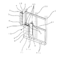
これら各図において、映像表示装置1は筐体2に複数の表示ユニット3が上下左右に隙間無く配置されて構成される。表示ユニット3は、例えば有機ELなどの表示パネル4を複数実装されて構成されており、この表示パネル4には画素が行列状に配置されている。
In each of these drawings, the
ここで表示ユニット3の寸法精度と組立精度が重要であり、表示ユニット3間にズレが生じると大画面表示した場合に表示のズレ及び暗線・明線等が表われる。表示ユニット3のズレは、表示のズレになって現われ、表示ユニット3間の寸法のばらつきは、例えば隣接する表示ユニット3の間隔が広すぎると、表示ユニット3間の画素間隔の拡大が輝度の低下として知覚されることで暗線となり、逆に隣接する表示ユニット3の間隔が狭すぎると、表示ユニット3間の画素間隔の短縮が輝度の向上として知覚されることで明線となる。
Here, the dimensional accuracy and the assembly accuracy of the
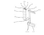
ここでは表示ユニット3の寸法精度を改善するために、図2および図3に示すように、表示ユニット3は、固定用ブラケット5に取り付けられ、固定用ブラケット5の上部側に設けられた上部側ブラケット6と、固定用ブラケット5の下部側に設けられた下部側ブラケット7と、表示パネル4と、上部側ブラケット6に取り付けられた固定用サポート10と、基板(図示せず)で構成され、表示ユニット3単体での寸法が高精度化できる。さらに各表示ユニット3を高精度の筐体2のベース11に積み上げることで、大型の映像表示装置1を高精度で組立てることができる。
Here, in order to improve the dimensional accuracy of the
下部側ブラケット7には例えば位置決め突起で構成された第1の係合体8が設けられ、上部側ブラケット6には位置決め突起で構成された第1の係合体8が嵌合する例えば位置決め穴で構成された第2の係合体9が設けられている。
The
この構造によれば、まず表示ユニット3単体での寸法精度が重要である。表示ユニット3は、図7に示すように、固定用ブラケット5のA寸法の精度を要求されるので、固定用ブラケット5の形状は板金部品の抜き加工部分で精度を必要とする形状を形成し、各固定用ブラケット(図示せず)の固定部分の曲げ部については固定用ブラケット5間にクリアランスを設けて固定する方法を取る。こうすることで、抜き加工部分の精度のみで管理できるので、表示ユニット3の精度が出すことができる。また、部品の精度のみではなく、組立治具を用いることで、表示パネル4を含む構成部品の組立てによるバラツキも無くなる。
According to this structure, first, the dimensional accuracy of the
次に表示ユニット3を積み上げるための基準となる筐体2のベース11が重要である。筐体2のベース11は、図4〜図6に示すように、表示ユニット3の位置を設定するための位置設定穴11aが加工されている。このベース11および位置設定穴11aの寸法精度を出すことで、表示ユニット3の位置が設定される。
Next, the
最下段に位置する表示ユニット3の下部側ブラケット7に設けられた位置決め突起で構成された第1の係合体8を筐体2のベース11に設けられた位置設定穴11aに差し込み、固定用サポート10を固定ネジ12により筐体2の横フレーム21に固定する。これにより、最下段に位置する表示ユニット3の取り付けが完了する。なお、横フレーム21を補強する縦フレーム22が設けられている。
The
この積み上げ構造により、一番下側の表示ユニット3をベース11にて精度良く組立てた後は、表示ユニット3の上に、別の表示ユニット3の位置決め突起で構成された第1の係合体8を位置決め穴で構成された第2の係合体9に差し込み積み上げていくことで、表示ユニット3間のズレを最小限にした大画面の表示装置1が形成できることになる。但し、この積み上げ方式で精度を出す場合は、筐体2のベース11の精度と表示ユニット3の精度が要求されることになる。
With this stacked structure, after the
そして、隣の一番下側の表示ユニット3をベース11にて精度良く組立てた後は、表示ユニット3の上に、別の表示ユニット3の位置決め突起で構成された第1の係合体8を位置決め穴で構成された第2の係合体9に差し込み積み上げていくことで、表示ユニット3間のズレを最小限にした大画面の表示装置1が形成できることになる。
Then, after the next
実施の形態2.
この発明の実施の形態2を図8に基づいて説明する。図8はこの発明の実施の形態2に係わる映像表示装置における表示ユニットを示す斜視図である。
A second embodiment of the present invention will be described with reference to FIG. FIG. 8 is a perspective view showing a display unit in a video display apparatus according to
筐体2のベース11の精度が出ていない場合、表示ユニット3を固定ネジ12で固定すると、筐体2の精度に左右されて、表示ユニット3が傾いた状態で固定されることになる。筐体2の精度が出ていない場合は、図8に示すように、固定用サポート61が前後左右及び回転方向に自由に可動できるように構成しており、固定ネジ12を緩め、固定用サポート61を可動させることにより筐体2の精度不足に左右されることなく表示ユニット3を水平、垂直に精度よく固定することができる。
When the accuracy of the
この積み上げ構造により、一番下側の表示ユニット3を筐体2のベース11にて精度良く組み立てた後は、表示ユニット3の上に、別の表示ユニット3の位置決め突起で構成された第1の係合体8を位置決め穴で構成された第2の係合体9に差し込み積み上げていくことで、表示ユニット3間のズレを最小限にした大画面の映像表示装置1が形成できることになる。
With this stacked structure, after the
このように、この積み上げ方式、また固定用サポート61が自由に固定位置を調整できるようにしたことにより、表示ユニット3間のズレを補正することができ、大画面の映像表示装置1が形成できるメリットがある。
As described above, since this stacking method and the fixing support 61 can freely adjust the fixing position, the shift between the
実施の形態3.
この発明の実施の形態3を図9および図10に基づいて説明するが、各図において、同一、または相当部材、部位については同一符号を付して説明する。図9はこの発明の実施の形態3に係わる映像表示装置を示す斜視図である。図10はこの発明の実施の形態3に係わる映像表示装置を示す斜視図である。
A third embodiment of the present invention will be described with reference to FIGS. 9 and 10. In the drawings, the same or corresponding members and parts are denoted by the same reference numerals. FIG. 9 is a perspective view showing a video display apparatus according to
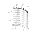
上述した各実施の形態においては映像表示装置1が平面的な場合について述べたが、この発明の実施の形態3においては、筐体2のベース11の形状を曲面であるR形状に形成し、このR形状のベース11に対応して筐体2の横フレーム(図示せず)の形状を曲面であるR形状に形成することにより、表示ユニット3を曲面状に配列させることができるので、図9および図10に示すような曲面であるRスクリーン(凹凸)が形成でき、様々なパターンの形状が可能となる。例えばR形状は、図9および図10の凸型や凹型の曲率を任意に設定できる。さらに、凸型や凹型に限らず、波型などの特殊な構造にも対応できる。
In each of the embodiments described above, the case where the
ところで、上述した各実施の形態においては、表示ユニット3を縦方向に積み上げて組み立てた後、隣の表示ユニット3を順次縦方向に積み上げて組み立てていく場合について
述べたが、これに限定されるものではなく、最下段の表示ユニット3を横方向にすべて筐体2のベース11に組み付けた後、2段目以降の表示ユニット3を横方向にすべて前段の表示ユニット3に組み付けるようにしてもよく、同様の効果を奏する。
By the way, in each of the above-described embodiments, the case where the
また、第1の係合体8は位置決め突起で構成され、第2の係合体9は位置決め穴で構成された場合について述べたが、これに限定されるものではなく、第1の係合体8は位置決め穴で構成され、第2の係合体9は位置決め突起で構成されようにしてもよく、同様の効果を奏する。なお、この場合は筐体2のベース11には位置設定穴11aではなく位置設定突起が設けられる。
Moreover, although the
なお、この発明は、その発明の範囲内において、各実施の形態を自由に組み合わせたり、各実施の形態を適宜、変形、省略することが可能である。 It should be noted that within the scope of the present invention, the embodiments can be freely combined, or the embodiments can be appropriately modified or omitted.
この発明は、表示ユニットの組立精度を高度化することができる映像表示装置の実現に好適である。 The present invention is suitable for realizing a video display device capable of enhancing the assembly accuracy of a display unit.
1 映像表示装置
2 筐体
3 表示ユニット
4 表示パネル
5 固定用ブラケット
6 上部側ブラケット
7 下部側ブラケット
8 第1の係合体
9 第2の係合体
10 固定用サポート
11 ベース
11a 位置設定穴
101 固定用サポート
DESCRIPTION OF
Claims (4)
Priority Applications (1)
| Application Number | Priority Date | Filing Date | Title |
|---|---|---|---|
| JP2012058168A JP5999940B2 (en) | 2012-03-15 | 2012-03-15 | Video display device |
Applications Claiming Priority (1)
| Application Number | Priority Date | Filing Date | Title |
|---|---|---|---|
| JP2012058168A JP5999940B2 (en) | 2012-03-15 | 2012-03-15 | Video display device |
Publications (3)
| Publication Number | Publication Date |
|---|---|
| JP2013190716A JP2013190716A (en) | 2013-09-26 |
| JP2013190716A5 JP2013190716A5 (en) | 2015-04-30 |
| JP5999940B2 true JP5999940B2 (en) | 2016-09-28 |
Family
ID=49390993
Family Applications (1)
| Application Number | Title | Priority Date | Filing Date |
|---|---|---|---|
| JP2012058168A Active JP5999940B2 (en) | 2012-03-15 | 2012-03-15 | Video display device |
Country Status (1)
| Country | Link |
|---|---|
| JP (1) | JP5999940B2 (en) |
Families Citing this family (1)
| Publication number | Priority date | Publication date | Assignee | Title |
|---|---|---|---|---|
| JP6511180B2 (en) * | 2018-03-27 | 2019-05-15 | パナソニック株式会社 | Display mounting jig |
Family Cites Families (8)
| Publication number | Priority date | Publication date | Assignee | Title |
|---|---|---|---|---|
| JPH07104652B2 (en) * | 1986-09-19 | 1995-11-13 | 松下電器産業株式会社 | Large display |
| JPH01127114U (en) * | 1988-02-24 | 1989-08-30 | ||
| JPH0950766A (en) * | 1995-08-03 | 1997-02-18 | Matsushita Electron Corp | Gas discharge display panel and image display device using same |
| JP2001100651A (en) * | 1999-09-30 | 2001-04-13 | Matsushita Electric Ind Co Ltd | Wall hanging type display device |
| JP2004354571A (en) * | 2003-05-28 | 2004-12-16 | Toshiba Transport Eng Inc | Video display device |
| JP2004354570A (en) * | 2003-05-28 | 2004-12-16 | Toshiba Transport Eng Inc | Video display device |
| JP5089857B2 (en) * | 2004-11-19 | 2012-12-05 | アビックス株式会社 | Large screen LED display system |
| JP5105123B2 (en) * | 2009-01-06 | 2012-12-19 | Necディスプレイソリューションズ株式会社 | Multi-screen display device fixing structure and fixing method |
-
2012
- 2012-03-15 JP JP2012058168A patent/JP5999940B2/en active Active
Also Published As
| Publication number | Publication date |
|---|---|
| JP2013190716A (en) | 2013-09-26 |
Similar Documents
| Publication | Publication Date | Title |
|---|---|---|
| JP5105123B2 (en) | Multi-screen display device fixing structure and fixing method | |
| JP4896583B2 (en) | Display device | |
| JP4883659B2 (en) | Multi-screen display device fixing structure and fixing method | |
| JP2008052133A (en) | Wall-hanging device and method for thin display | |
| JP4342599B1 (en) | Display device | |
| JP2007304279A (en) | Liquid crystal display device | |
| US20230209749A1 (en) | Multi-display device | |
| JP2018092060A (en) | Display device | |
| JP5999940B2 (en) | Video display device | |
| JP2010185924A (en) | Liquid crystal display and method for manufacturing the same | |
| JP2009265223A (en) | Thin display device | |
| WO2020225907A1 (en) | Image display device and method for manufacturing same | |
| CN105009189A (en) | Flat-screen display device | |
| JP5687973B2 (en) | Solar cell module fixture and solar cell device | |
| JP2012150371A (en) | Image display device | |
| WO2018131158A1 (en) | Multi-display system and drawing mechanism | |
| CN103955094B (en) | Frame mechanism for optical equipment | |
| JP5123416B2 (en) | Display device | |
| JP5106693B2 (en) | Television receiver and electronic device | |
| CN220528415U (en) | Arc-shaped screen frame and LED display screen | |
| JP4945666B2 (en) | Television receiver | |
| EP4134936A1 (en) | System and method for installing display device | |
| JP2009237511A (en) | Display device and its installation method | |
| KR20170072399A (en) | Guide pin and video wall using the same | |
| EP2040110A3 (en) | Rear frame for a liquid crystal display module |
Legal Events
| Date | Code | Title | Description |
|---|---|---|---|
| A521 | Request for written amendment filed |
Free format text: JAPANESE INTERMEDIATE CODE: A523 Effective date: 20150311 |
|
| A621 | Written request for application examination |
Free format text: JAPANESE INTERMEDIATE CODE: A621 Effective date: 20150311 |
|
| A131 | Notification of reasons for refusal |
Free format text: JAPANESE INTERMEDIATE CODE: A131 Effective date: 20160126 |
|
| A977 | Report on retrieval |
Free format text: JAPANESE INTERMEDIATE CODE: A971007 Effective date: 20160127 |
|
| A521 | Request for written amendment filed |
Free format text: JAPANESE INTERMEDIATE CODE: A523 Effective date: 20160314 |
|
| TRDD | Decision of grant or rejection written | ||
| A01 | Written decision to grant a patent or to grant a registration (utility model) |
Free format text: JAPANESE INTERMEDIATE CODE: A01 Effective date: 20160802 |
|
| A61 | First payment of annual fees (during grant procedure) |
Free format text: JAPANESE INTERMEDIATE CODE: A61 Effective date: 20160830 |
|
| R151 | Written notification of patent or utility model registration |
Ref document number: 5999940 Country of ref document: JP Free format text: JAPANESE INTERMEDIATE CODE: R151 |
|
| R250 | Receipt of annual fees |
Free format text: JAPANESE INTERMEDIATE CODE: R250 |
|
| R250 | Receipt of annual fees |
Free format text: JAPANESE INTERMEDIATE CODE: R250 |
|
| R250 | Receipt of annual fees |
Free format text: JAPANESE INTERMEDIATE CODE: R250 |
|
| R250 | Receipt of annual fees |
Free format text: JAPANESE INTERMEDIATE CODE: R250 |
|
| R250 | Receipt of annual fees |
Free format text: JAPANESE INTERMEDIATE CODE: R250 |