JP5998486B2 - Blood pressure measuring device and method for controlling blood pressure measuring device - Google Patents
Blood pressure measuring device and method for controlling blood pressure measuring device Download PDFInfo
- Publication number
- JP5998486B2 JP5998486B2 JP2012006092A JP2012006092A JP5998486B2 JP 5998486 B2 JP5998486 B2 JP 5998486B2 JP 2012006092 A JP2012006092 A JP 2012006092A JP 2012006092 A JP2012006092 A JP 2012006092A JP 5998486 B2 JP5998486 B2 JP 5998486B2
- Authority
- JP
- Japan
- Prior art keywords
- cuff
- pressure
- control
- frequency
- voltage
- Prior art date
- Legal status (The legal status is an assumption and is not a legal conclusion. Google has not performed a legal analysis and makes no representation as to the accuracy of the status listed.)
- Active
Links
Images


Classifications
-
- A—HUMAN NECESSITIES
- A61—MEDICAL OR VETERINARY SCIENCE; HYGIENE
- A61B—DIAGNOSIS; SURGERY; IDENTIFICATION
- A61B5/00—Measuring for diagnostic purposes; Identification of persons
- A61B5/02—Detecting, measuring or recording pulse, heart rate, blood pressure or blood flow; Combined pulse/heart-rate/blood pressure determination; Evaluating a cardiovascular condition not otherwise provided for, e.g. using combinations of techniques provided for in this group with electrocardiography or electroauscultation; Heart catheters for measuring blood pressure
- A61B5/021—Measuring pressure in heart or blood vessels
- A61B5/022—Measuring pressure in heart or blood vessels by applying pressure to close blood vessels, e.g. against the skin; Ophthalmodynamometers
- A61B5/02233—Occluders specially adapted therefor
-
- A—HUMAN NECESSITIES
- A61—MEDICAL OR VETERINARY SCIENCE; HYGIENE
- A61B—DIAGNOSIS; SURGERY; IDENTIFICATION
- A61B5/00—Measuring for diagnostic purposes; Identification of persons
- A61B5/02—Detecting, measuring or recording pulse, heart rate, blood pressure or blood flow; Combined pulse/heart-rate/blood pressure determination; Evaluating a cardiovascular condition not otherwise provided for, e.g. using combinations of techniques provided for in this group with electrocardiography or electroauscultation; Heart catheters for measuring blood pressure
- A61B5/021—Measuring pressure in heart or blood vessels
- A61B5/022—Measuring pressure in heart or blood vessels by applying pressure to close blood vessels, e.g. against the skin; Ophthalmodynamometers
- A61B5/0225—Measuring pressure in heart or blood vessels by applying pressure to close blood vessels, e.g. against the skin; Ophthalmodynamometers the pressure being controlled by electric signals, e.g. derived from Korotkoff sounds
-
- A—HUMAN NECESSITIES
- A61—MEDICAL OR VETERINARY SCIENCE; HYGIENE
- A61B—DIAGNOSIS; SURGERY; IDENTIFICATION
- A61B2562/00—Details of sensors; Constructional details of sensor housings or probes; Accessories for sensors
- A61B2562/02—Details of sensors specially adapted for in-vivo measurements
- A61B2562/0247—Pressure sensors
-
- A—HUMAN NECESSITIES
- A61—MEDICAL OR VETERINARY SCIENCE; HYGIENE
- A61B—DIAGNOSIS; SURGERY; IDENTIFICATION
- A61B5/00—Measuring for diagnostic purposes; Identification of persons
- A61B5/68—Arrangements of detecting, measuring or recording means, e.g. sensors, in relation to patient
- A61B5/6801—Arrangements of detecting, measuring or recording means, e.g. sensors, in relation to patient specially adapted to be attached to or worn on the body surface
- A61B5/683—Means for maintaining contact with the body
- A61B5/6831—Straps, bands or harnesses
Landscapes
- Health & Medical Sciences (AREA)
- Life Sciences & Earth Sciences (AREA)
- Cardiology (AREA)
- Vascular Medicine (AREA)
- Engineering & Computer Science (AREA)
- Medical Informatics (AREA)
- Physics & Mathematics (AREA)
- Ophthalmology & Optometry (AREA)
- Biophysics (AREA)
- Pathology (AREA)
- Veterinary Medicine (AREA)
- Biomedical Technology (AREA)
- Heart & Thoracic Surgery (AREA)
- Physiology (AREA)
- Molecular Biology (AREA)
- Surgery (AREA)
- Animal Behavior & Ethology (AREA)
- General Health & Medical Sciences (AREA)
- Public Health (AREA)
- Dentistry (AREA)
- Measuring Pulse, Heart Rate, Blood Pressure Or Blood Flow (AREA)
Description
この発明は、血圧測定装置、および、血圧測定装置の制御方法に関し、特に、カフの加圧過程における血圧の測定に適した血圧測定装置、および、血圧測定装置の制御方法に関する。 The present invention relates to a blood pressure measurement device and a method for controlling the blood pressure measurement device, and more particularly, to a blood pressure measurement device suitable for measuring blood pressure in a cuff pressurizing process and a method for controlling the blood pressure measurement device.
一般的な電子血圧計としてオシロメトリック法を用いた電子血圧計が用いられている。オシロメトリック法を用いた電子血圧計では、空気袋を内蔵した腕帯を生体の一部に均等に巻き付け、その空気袋を空気により加減圧することにより、圧迫された動脈血管の容積変化を空気袋圧力(カフ圧)の変動の振幅変化として捕らえ、血圧を算出する。カフを加圧しながら精度よく血圧測定を行うためには、カフ内圧の加圧速度を適正に制御する必要がある。 As a general electronic blood pressure monitor, an electronic blood pressure monitor using an oscillometric method is used. In an electronic sphygmomanometer using the oscillometric method, an arm band with an air bag is evenly wrapped around a part of a living body, and the air bag is pressurized and depressurized with air, so that the volume change of the compressed arterial blood vessel is changed to air. The blood pressure is calculated by capturing the change in the amplitude of the bag pressure (cuff pressure). In order to accurately measure blood pressure while pressurizing the cuff, it is necessary to appropriately control the pressurization speed of the cuff internal pressure.
特許文献1では、圧電素子を用いて駆動する圧電マイクロポンプが提案されており、電子血圧計への応用が考えられる。また、特許文献2および特許文献3などでは、駆動周波数は圧電素子とダイアフラムの材質で決定され、駆動周波数付近で制御することが提案されている。
しかしながら、このような高圧力でのポンプ駆動では圧電ポンプの消費電力が増大するため、電池交換なく血圧測定できる回数が少なくなってしまう。このため、ポンプ本来の機械的効率改善が必要である。 However, when the pump is driven at such a high pressure, the power consumption of the piezoelectric pump increases, and the number of times that blood pressure can be measured without battery replacement is reduced. For this reason, it is necessary to improve the mechanical efficiency inherent to the pump.
特許文献4では、ポンプ流量出力制御において、電流、電圧、Dutyなどで制御する方法が提案されている。
しかしながら、特許文献4の技術では、ポンプ流量出力が同じでも、電圧および周波数によりポンプ電力効率が変化し、最大のポンプ電力効率にできない場合がある。
However, in the technique of
この発明は、上述の問題を解決するためになされたものであり、その目的の1つは、血圧測定のためのカフ圧の加圧過程において圧電ポンプを用いて加圧する場合に、消費電力を減少させることが可能な血圧測定装置および血圧測定装置の制御方法を提供することである。 The present invention has been made to solve the above-described problems, and one of its purposes is to reduce power consumption when pressurizing using a piezoelectric pump in the process of pressurizing cuff pressure for blood pressure measurement. It is an object to provide a blood pressure measurement device that can be decreased and a method for controlling the blood pressure measurement device.
上述の目的を達成するために、この発明のある局面によれば、血圧測定装置は、血圧の測定部位に装着された場合に内部の流体の圧力で測定部位の動脈を圧迫するカフと、カフの内部の圧力を加圧する圧電ポンプと、カフの内部の圧力を減圧する減圧部と、カフの内部の圧力であるカフ圧を検出する圧力検出部と、制御部とを有する。 In order to achieve the above-described object, according to one aspect of the present invention, a blood pressure measurement device includes: a cuff that compresses an artery of a measurement site with the pressure of an internal fluid when the blood pressure measurement device is attached to the blood pressure measurement site; A pressure pump that pressurizes the pressure inside the cuff, a pressure reducing unit that reduces the pressure inside the cuff, a pressure detecting unit that detects cuff pressure that is the pressure inside the cuff, and a control unit.
制御部は、圧電ポンプに印加する電圧の振幅と周波数とを決定する決定部と、決定部によって決定された振幅および周波数の電圧を圧電ポンプに印加するよう制御する印加電圧制御部と、圧電ポンプによってカフ圧を加圧する加圧過程において圧力検出部によって検出されるカフ圧に基づいて血圧値を算出する血圧測定部とを含む。決定部は、電圧を所定電圧として加圧過程において必要な流量をカフに供給する場合に圧電ポンプのポンプ効率が最大となる制御周波数を決定する。印加電圧制御部は、所定電圧の振幅および決定部によって決定された制御周波数の電圧を印加する第1の制御を行なう。 The control unit includes a determination unit that determines the amplitude and frequency of the voltage applied to the piezoelectric pump, an application voltage control unit that controls the voltage of the amplitude and frequency determined by the determination unit to be applied to the piezoelectric pump, And a blood pressure measurement unit that calculates a blood pressure value based on the cuff pressure detected by the pressure detection unit in the pressurizing process of increasing the cuff pressure. The determining unit determines a control frequency at which the pump efficiency of the piezoelectric pump is maximized when a necessary flow rate is supplied to the cuff in the pressurizing process using the voltage as a predetermined voltage. The applied voltage control unit performs first control for applying a voltage having a predetermined frequency and a control frequency determined by the determining unit.
好ましくは、決定部は、周波数を所定周波数として加圧過程において必要な流量をカフに供給する場合にポンプ効率が最大となる制御電圧を決定する。印加電圧制御部は、加圧過程の最初から途中の所定時までは、第1の制御を行ない、所定時から加圧過程の終了までは、所定周波数および決定部によって決定された制御電圧を印加する第2の制御を行なう。 Preferably, the determination unit determines a control voltage at which pump efficiency is maximized when a necessary flow rate is supplied to the cuff in the pressurizing process with a frequency as a predetermined frequency. The applied voltage control unit performs the first control from the beginning of the pressurizing process to a predetermined time in the middle, and applies the predetermined frequency and the control voltage determined by the determining unit from the predetermined time to the end of the pressurizing process. The second control is performed.
この発明の他の局面によれば、血圧測定装置は、血圧の測定部位に装着された場合に内部の流体の圧力で測定部位の動脈を圧迫するカフと、カフの内部の圧力を加圧する圧電ポンプと、カフの内部の圧力を減圧する減圧部と、カフの内部の圧力であるカフ圧を検出する圧力検出部と、制御部とを有する。 According to another aspect of the present invention, a blood pressure measurement device includes a cuff that compresses an artery of a measurement site with the pressure of an internal fluid when the blood pressure measurement device is attached to a blood pressure measurement site, and a piezoelectric that pressurizes the pressure inside the cuff. The pump includes a pressure reducing unit that reduces the pressure inside the cuff, a pressure detecting unit that detects the cuff pressure that is the pressure inside the cuff, and a control unit.
制御部は、圧電ポンプに印加する電圧の振幅と周波数とを決定する決定部と、決定部によって決定された振幅および周波数の電圧を圧電ポンプに印加するよう制御する印加電圧制御部と、圧電ポンプによってカフ圧を加圧する加圧過程において圧力検出部によって検出されるカフ圧に基づいて血圧値を算出する血圧測定部とを含む。決定部は、周波数を所定周波数として加圧過程において必要な流量をカフに供給する場合にポンプ効率が最大となる制御電圧を決定する。印加電圧制御部は、所定周波数および決定部によって決定された制御電圧を印加する第2の制御を行なう。 The control unit includes a determination unit that determines the amplitude and frequency of the voltage applied to the piezoelectric pump, an application voltage control unit that controls the voltage of the amplitude and frequency determined by the determination unit to be applied to the piezoelectric pump, And a blood pressure measurement unit that calculates a blood pressure value based on the cuff pressure detected by the pressure detection unit in the pressurizing process of increasing the cuff pressure. The determining unit determines a control voltage at which the pump efficiency is maximized when supplying a necessary flow rate to the cuff in the pressurizing process with a predetermined frequency. The applied voltage control unit performs second control to apply the control voltage determined by the predetermined frequency and the determination unit.
好ましくは、決定部は、電圧を所定電圧として加圧過程において必要な流量をカフに供給する場合にポンプ効率が最大となる制御周波数を決定する。印加電圧制御部は、加圧過程の最初から途中の所定時までは、所定電圧の振幅および決定部によって決定された制御周波数の電圧を印加する第1の制御を行ない、所定時から加圧過程の終了までは、第2の制御を行なう。 Preferably, the determination unit determines a control frequency at which pump efficiency is maximized when the voltage is set to a predetermined voltage and a flow rate necessary for the pressurization process is supplied to the cuff. The applied voltage control unit performs the first control to apply the voltage having the amplitude of the predetermined voltage and the control frequency determined by the determining unit from the beginning of the pressurizing process to a predetermined time in the middle, and from the predetermined time to the pressurizing process Until the end of, the second control is performed.
さらに好ましくは、所定時は、カフ圧が所定圧力になったときであり、所定圧力は、必要な流量ごとに予め定められ、必要な流量は、カフの大きさ、測定部位の大きさ、測定部位へのカフの装着状況に基づいて予め定められる。 More preferably, the predetermined time is when the cuff pressure becomes a predetermined pressure, and the predetermined pressure is predetermined for each required flow rate, and the required flow rate is determined by the size of the cuff, the size of the measurement site, and the measurement. It is determined in advance based on the state of wearing the cuff on the part.
この発明のさらに他の局面によれば、血圧測定装置の制御方法は、血圧の測定部位に装着された場合に内部の流体の圧力で測定部位の動脈を圧迫するカフと、カフの内部の圧力を加圧する圧電ポンプと、カフの内部の圧力を減圧する減圧部と、カフの内部の圧力であるカフ圧を検出する圧力検出部と、制御部とを有する血圧測定装置の制御方法である。 According to still another aspect of the present invention, a method for controlling a blood pressure measurement device includes: a cuff that compresses an artery of a measurement site with the pressure of an internal fluid when the blood pressure measurement device is attached to the blood pressure measurement site; Is a pressure-reducing unit that depressurizes the pressure inside the cuff, a pressure detecting unit that detects cuff pressure that is the pressure inside the cuff, and a control unit.
制御方法は、制御部が、圧電ポンプに印加する電圧の振幅と周波数とを決定するステップと、決定された振幅および周波数の電圧を圧電ポンプに印加するよう制御するステップと、圧電ポンプによってカフ圧を加圧する加圧過程において圧力検出部によって検出されるカフ圧に基づいて血圧値を算出するステップとを含む。決定するステップは、電圧を所定電圧として加圧過程において必要な流量をカフに供給する場合に圧電ポンプのポンプ効率が最大となる制御周波数を決定するステップを含む。制御するステップは、所定電圧の振幅および決定された制御周波数の電圧を印加する第1の制御を行なうステップを含む。 In the control method, the control unit determines the amplitude and frequency of the voltage to be applied to the piezoelectric pump, controls to apply the voltage of the determined amplitude and frequency to the piezoelectric pump, and the cuff pressure by the piezoelectric pump. Calculating a blood pressure value based on the cuff pressure detected by the pressure detection unit in the pressurizing process of pressurizing. The step of determining includes a step of determining a control frequency at which the pump efficiency of the piezoelectric pump is maximized when a necessary flow rate is supplied to the cuff in the pressurizing process using the voltage as a predetermined voltage. The step of controlling includes the step of performing a first control of applying a voltage having a predetermined voltage amplitude and a determined control frequency.
この発明に従えば、血圧測定装置によって、圧電ポンプに印加する電圧の振幅と周波数とが決定され、決定された振幅および周波数の電圧が圧電ポンプに印加されるよう制御され、圧電ポンプによってカフ圧を加圧する加圧過程において圧力検出部によって検出されるカフ圧に基づいて血圧値が算出される。電圧を所定電圧として加圧過程において必要な流量をカフに供給する場合に圧電ポンプのポンプ効率が最大となる制御周波数が決定される。所定電圧の振幅および決定された制御周波数の電圧を印加する第1の制御が行なわれる。 According to the present invention, the blood pressure measurement device determines the amplitude and frequency of the voltage applied to the piezoelectric pump, and controls the voltage of the determined amplitude and frequency to be applied to the piezoelectric pump. A blood pressure value is calculated based on the cuff pressure detected by the pressure detection unit in the pressurizing process of pressurizing. The control frequency at which the pump efficiency of the piezoelectric pump is maximized is determined when the required flow rate is supplied to the cuff in the pressurizing process using the voltage as a predetermined voltage. A first control for applying a voltage having a predetermined voltage amplitude and a determined control frequency is performed.
このため、加圧過程において必要な流量をカフに供給する場合に電圧を所定電圧として圧電ポンプのポンプ効率が最大となる制御周波数と所定電圧とで圧電ポンプが駆動されるので、他の制御周波数および所定電圧で圧電ポンプを駆動する場合と比較して、消費電力を減少させることができる。その結果、血圧測定のためのカフ圧の加圧過程において圧電ポンプを用いて加圧する場合に、消費電力を減少させることが可能な血圧測定装置および血圧測定装置の制御方法を提供することができる。 For this reason, when supplying the required flow rate to the cuff during the pressurizing process, the piezoelectric pump is driven at a control frequency that maximizes the pump efficiency of the piezoelectric pump with a predetermined voltage, and other control frequencies. In addition, power consumption can be reduced as compared with the case where the piezoelectric pump is driven at a predetermined voltage. As a result, it is possible to provide a blood pressure measurement device and a control method for the blood pressure measurement device that can reduce power consumption when pressure is applied using a piezoelectric pump in the process of applying cuff pressure for blood pressure measurement. .
以下、この発明の実施の形態について、図面を参照しながら詳細に説明する。なお、図中の同一または相当部分については、同一符号を付してその説明は繰返さない。 Hereinafter, embodiments of the present invention will be described in detail with reference to the drawings. Note that the same or corresponding parts in the drawings are denoted by the same reference numerals and description thereof will not be repeated.
この実施の形態においては、オシロメトリック方式の加圧測定型の血圧計において加圧測定しているときの圧電ポンプの駆動制御についての発明の実施の形態を説明する。しかし、これに限定されず、この発明は、圧電ポンプによる加圧過程がある血圧計であれば、他の方式の血圧計であっても適用可能であり、たとえば、減圧測定型の血圧計にも適用可能である。 In this embodiment, an embodiment of the invention relating to drive control of a piezoelectric pump when pressurization measurement is performed in an oscillometric pressurization type blood pressure monitor will be described. However, the present invention is not limited to this, and the present invention can be applied to other types of sphygmomanometers as long as the sphygmomanometer has a pressurizing process using a piezoelectric pump. Is also applicable.
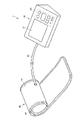
まず、この実施の形態における血圧計1の構成について説明する。図1は、この発明の実施の形態における血圧計1の外観を示す斜視図である。図1を参照して、この実施の形態における血圧計1は、本体10と、カフ40と、エア管50とを備えている。本体10は、箱状の筐体を有しており、その上面に表示部21および操作部23を有している。本体10は、測定時においてテーブル等の載置面に載置されて使用される。
First, the configuration of the
カフ40は、帯状でかつ袋状の外装カバー41と、当該外装カバー41に内包された圧迫用流体袋としての圧迫用空気袋42とを主として有しており、全体として略環状の形態を有している。カフ40は、測定時において被験者の上腕に巻き付けられて装着されることで使用される。エア管50は、分離して構成された本体10とカフ40とを接続している。
The
図2は、この実施の形態における血圧計1の構成の概略を示すブロック図である。図2を参照して、本体10は、上述した表示部21および操作部23に加え、制御部20と、メモリ部22と、電源部24と、圧電ポンプ31と、排気弁32と、圧力センサ33と、DC−DC昇圧回路61と、電圧制御回路62と、駆動制御回路63と、増幅器71と、A/D変換器72とを有している。圧電ポンプ31および排気弁32は、圧迫用空気袋42の内圧を加減圧するための加減圧機構に相当する。
FIG. 2 is a block diagram showing an outline of the configuration of the
圧迫用空気袋42は、装着状態において上腕を圧迫するためのものであり、その内部に内腔を有している。圧迫用空気袋42は、上述したエア管50を介して上述した圧電ポンプ31、排気弁32および圧力センサ33のそれぞれに接続されている。これにより、圧迫用空気袋42は、圧電ポンプ31が駆動することで加圧されて膨張し、排出弁としての排気弁32の駆動が制御されることでその内圧が維持されたり減圧されて収縮したりする。
The
制御部20は、たとえばCPU(Central Processing Unit)で構成され、血圧計1の全体を制御するための手段である。
The
表示部21は、たとえばLCD(Liquid Crystal Display)で構成され、測定結果等を表示するための手段である。
The
メモリ部22は、たとえばROM(Read-Only Memory)やRAM(Random-Access Memory)で構成され、血圧値測定のための処理手順を制御部20等に実行させるためのプログラムを記憶したり、測定結果等を記憶したりするための手段である。
The
操作部23は、被験者等による操作を受付けて、この外部からの命令を制御部20や電源部24に入力するための手段である。
The
電源部24は、制御部20および圧電ポンプ31などの血圧計1の各部に電力を供給するための手段であり、この実施の形態においては、電池である。しかし、これに限定されず、電源部24は、商用電源などの外部電源から電力の供給を受けるようにしてもよい。
The
制御部20は、圧電ポンプ31および排気弁32を駆動するための制御信号を、電圧制御回路62および駆動制御回路63にそれぞれ入力したり、測定結果としての血圧値を表示部21やメモリ部22に入力したりする。また、制御部20は、圧力センサ33から増幅器71およびA/D変換器72を介して検出された圧力値に基づいて被験者の血圧値を取得する血圧情報取得部(不図示)を含んでおり、この血圧情報取得部によって取得された血圧値が、測定結果として上述した表示部21やメモリ部22に入力される。
The
なお、血圧計1は、測定結果としての血圧値を外部の機器、たとえば、PC(Personal Computer)やプリンタ等に出力する出力部を別途有していてもよい。出力部としては、たとえば、シリアル通信回線や各種の記録媒体への書き込み装置等が利用可能である。
The
DC−DC昇圧回路61は、電源部24である電池の電圧を、圧電ポンプ31の駆動に適した電圧に昇圧する回路である。
The DC-
電圧制御回路62は、制御部20から入力された制御信号で示される電圧値に基づいて圧電ポンプ31に供給する電圧を制御する。
The
駆動制御回路63は、制御部20から入力された制御信号に基づいて圧電ポンプ31および排気弁32を制御する。具体的には、駆動制御回路63は、制御部20から入力された制御信号で示される制御周波数に基づいて圧電ポンプ31に供給する電流の周波数を制御する。また、駆動制御回路63は、制御部20から入力された制御信号に基づいて排気弁32の開閉動作を制御する。
The
圧電ポンプ31は、圧迫用空気袋42の内腔に空気を供給することにより圧迫用空気袋42の内圧(以下、「カフ圧」とも称する)を加圧するためのものであり、その動作が上述した駆動制御回路63によって制御される。圧電ポンプ31は、所定の駆動周波数f0で所定の振幅V0の交流の電流が印加されることによって、所定の流量の空気を吐出する。なお、交流としては、正弦波状の交流であってもよいし、矩形波状の交流であってもよい。以下において、圧電ポンプ31に印加する電圧の値を示す場合には、ピーク間電位差Vp-pの値を用いる場合がある。振幅は、Vp-pの値の半分である。Vp-pの場合、たとえば、電圧の値は、−Vp-p/2からVp-p/2までの値で変化する。
The
排気弁32は、圧迫用空気袋42の内圧を維持したり、圧迫用空気袋42の内腔を外部に開放してカフ圧を減圧したりするためのものであり、その動作が上述した駆動制御回路63によって制御される。
The
圧力センサ33は、圧迫用空気袋42の内圧を検知してこれに応じた出力信号を増幅器71に入力する。増幅器71は、圧力センサ33から入力された信号のレベルを増幅する。A/D変換器72は、増幅器71で増幅された信号をデジタル信号化し、生成したデジタル信号を制御部20に入力する。
The
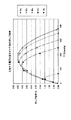
図3は、圧電ポンプ31に印加する電圧を変化させたときのポンプ効率を示すグラフである。図4は、電圧値に対して圧電ポンプ31が最大流量を出せる周波数を示すグラフである。ポンプ効率は、ポンプへの入力に対する出力の比率を示し、ポンプ効率(%)=圧力(ゲージ圧)×流量/消費電力の式で算出される。
FIG. 3 is a graph showing pump efficiency when the voltage applied to the
図3を参照して、これらのグラフは、圧電ポンプ31に印加する電圧を、それぞれ、10V、25V、30V、35V、38Vとした場合の、カフ40を加圧するときのカフ圧の上昇に伴なうポンプ効率の変化を示す。
Referring to FIG. 3, these graphs show the increase in cuff pressure when the
また、図4を参照して、電圧を、それぞれ、10V、25V、30V、35V、38Vとするときに、最大流量を出せる周波数が、それぞれ、23.30kHz、22.95kHz、22.85kHz、22.8kHz、22.65kHz程度の値であることが示される。図3において、それぞれの電圧とするときに、図4で示される周波数で、圧電ポンプ31を駆動することとする。
In addition, referring to FIG. 4, when the voltages are 10 V, 25 V, 30 V, 35 V, and 38 V, respectively, the frequencies at which the maximum flow rate can be obtained are 23.30 kHz, 22.95 kHz, 22.85 kHz, and 22 respectively. It is shown that the values are about .8 kHz and 22.65 kHz. In FIG. 3, when the respective voltages are set, the
このように、いずれの電圧においても、カフ圧の上昇の途中で、ポンプ効率が、最大となり、その後、減少する。また、電圧が高いほど、ポンプ効率が最大となるときのカフ圧が高くなる。また、電圧が高いほど、ポンプ効率が最大となるときのポンプ効率が高くなる。 As described above, at any voltage, the pump efficiency becomes the maximum during the increase of the cuff pressure, and then decreases. Also, the higher the voltage, the higher the cuff pressure when the pump efficiency is maximized. Further, the higher the voltage, the higher the pump efficiency when the pump efficiency is maximized.
図5は、圧電ポンプ31に印加する電圧が35Vのときのポンプ効率を示すグラフである。図5を参照して、圧電ポンプ31に印加する電圧を35Vとしたときに、カフ40を加圧するときのカフ圧の上昇に伴なうポンプ効率は、最大流量を出せる最適周波数である22.8kHzのときよりも、23.8kHzのときの方が、20%以上向上する。カフ圧が150mmHgに達するまでは、この周波数f0=23.8kHzがポンプ効率を最適にする周波数となる。
FIG. 5 is a graph showing the pump efficiency when the voltage applied to the
このように、カフ圧の範囲によって、ポンプ効率が最適となる電圧および駆動周波数が異なる。このため、カフ圧の範囲に応じて、ポンプに印加する電圧および駆動周波数を制御することが考えられる。 Thus, the voltage and driving frequency at which the pump efficiency is optimum differ depending on the range of the cuff pressure. For this reason, it is conceivable to control the voltage applied to the pump and the driving frequency in accordance with the range of the cuff pressure.
図6は、等速加圧制御において印加する電圧を制御する場合の圧電ポンプ31のポンプ効率の変化を説明するための図である。図6を参照して、血圧計1において血圧を測定するためには、カフを等速加圧する必要がある。このため、図6(A)で示すように、カフ圧P(mmHg)を200mmHgまで等速で加圧する場合についてのポンプ効率の変化を説明する。
FIG. 6 is a diagram for explaining a change in pump efficiency of the
図6(B)で示すように、カフの巻き具合および腕周が定まると、図6(A)で示すようにカフ圧Pを等速加圧させるために必要な流量Qt(mL/min)を定めることができる。このように、なだらかに流量Qtを減少させることによって、カフ圧Pを等速加圧させることができる。 As shown in FIG. 6 (B), when the cuff winding condition and arm circumference are determined, the flow rate Qt (mL / min) required to pressurize the cuff pressure P at a constant speed as shown in FIG. 6 (A). Can be determined. In this manner, the cuff pressure P can be increased at a constant speed by gently decreasing the flow rate Qt.
次に、図6(C)で示すように、図6(B)で示した流量Qtを圧電ポンプ31から吐出させるためには、電圧を制御する場合は、電圧Vo2をポンプの電圧−流量特性を元に増加させればよい。なお、駆動周波数fo2は、電圧Vo2の値に対して圧電ポンプ31が最大流量を吐出することが可能な周波数であり、図4で示したグラフに基づき求めることができる。
Next, as shown in FIG. 6C, in order to discharge the flow rate Qt shown in FIG. 6B from the
図6(D)で示すように、図6(C)で示した電圧Vo2および駆動周波数fo2で圧電ポンプ31を駆動することによるポンプ効率η2(%)は、加圧の時間の経過とともに上昇した後、下降する。
As shown in FIG. 6D, the pump efficiency η 2 (%) by driving the
図7は、等速加圧制御において印加する電圧の駆動周波数を制御する場合の圧電ポンプ31のポンプ効率の変化を説明するための図である。図7を参照して、図7(A)および図7(B)は、それぞれ、図6(A)および図6(B)と同一である。
FIG. 7 is a diagram for explaining a change in pump efficiency of the
図7(C)で示すように、図7(B)で示した流量Qtを圧電ポンプ31から吐出させるためには、駆動周波数を制御し、一定の電圧Vo1を印加する場合は、駆動周波数fo1をポンプの電圧−流量特性を元に減少させればよい。なお、本実施の形態においては、印加する電圧Vo1は、一定値とするが、これに限定されず、一定の変化をさせてもよい。
As shown in FIG. 7C, in order to discharge the flow rate Qt shown in FIG. 7B from the
図7(D)で示すように、図7(C)で示した電圧Vo1および駆動周波数fo1で圧電ポンプ31を駆動することによるポンプ効率η1(%)は、印加する電圧を制御する図6(D)の場合と同様、加圧の時間の経過とともに上昇した後、下降する。
As shown in FIG. 7D, the pump efficiency η1 (%) by driving the
図8は、周波数制御および電圧制御の場合のポンプ効率ならびに印加する電圧および駆動周波数の比較を示す図である。図8(A)を参照して、周波数制御および電圧制御の場合のそれぞれのポンプ効率η1,η2は、カフ圧P=P1(=150mmHg)のときに交差する。つまり、カフ圧がP1より小さいときは、周波数制御の場合の方がポンプ効率の値が高い。一方、カフ圧がP1より大きいときは、電圧制御の場合の方がポンプ効率の値が高い。 FIG. 8 is a diagram showing a comparison of pump efficiency and applied voltage and drive frequency in the case of frequency control and voltage control. Referring to FIG. 8A, the respective pump efficiencies η1 and η2 in the case of frequency control and voltage control intersect when cuff pressure P = P1 (= 150 mmHg). That is, when the cuff pressure is smaller than P1, the value of pump efficiency is higher in the case of frequency control. On the other hand, when the cuff pressure is greater than P1, the value of pump efficiency is higher in the case of voltage control.
このため、図8(B)で示すように、カフ圧がP1より小さいときは、一定の電圧Vo1を印加して駆動周波数fo1を制御し、カフ圧がP1より大きいときは、印加する電圧Vo2を制御して、電圧Vo2に応じて最大流量を吐出可能な駆動周波数fo2とする。 Therefore, as shown in FIG. 8B, when the cuff pressure is smaller than P1, a constant voltage Vo1 is applied to control the driving frequency fo1, and when the cuff pressure is larger than P1, the applied voltage Vo2 is applied. And a drive frequency fo2 at which the maximum flow rate can be discharged according to the voltage Vo2.
これにより、カフ圧がP1より小さいときは、電圧制御の場合のポンプ効率η2よりも高いポンプ効率η1の周波数制御で圧電ポンプ31を駆動することができるとともに、カフ圧がP1より大きいときは、周波数制御の場合のポンプ効率η1よりも高いポンプ効率η2の電圧制御で圧電ポンプ31を駆動することができる。
Thereby, when the cuff pressure is smaller than P1, the
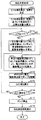
図9は、この実施の形態における血圧計1で実行される血圧測定処理の流れを示すフローチャートである。図9を参照して、まず、ステップS101で、血圧計1の制御部20は、カフ40の巻き具合および腕周を測定する。具体的には、カフ40に圧力が掛かっていない状態から、所定の流量をカフに流すよう圧電ポンプ31を制御して初期加圧を行ない、そのときの加圧速度を測定し、その測定された加圧速度に応じて巻き具合および腕周を推定する。この方法としては、たとえば、国際公開第2010/089917号に開示されている方法を用いることができる。
FIG. 9 is a flowchart showing the flow of blood pressure measurement processing executed by the
次に、ステップS102で、制御部20は、ステップS101で測定したカフ40の巻き具合および腕周に基づいて、カフ40の等速加圧に必要な流量Qtを算出する。具体的には、図6(B)および図7(B)で示したグラフを示すデータが、複数のカフ40の巻き具合および腕周の組合せごとに、予め、血圧計1のメモリ部22に記憶されており、測定された巻き具合および腕周の組合せに対応する必要な流量Qtのグラフを示すデータがメモリ部22から読出される。
Next, in step S102, the
ステップS111では、制御部20は、圧力センサ33で検出され、増幅器71およびA/D変換器72を介して制御部20に入力された信号によって示されるカフ圧が、図8で説明したP1未満であるか否かを判断する。
In step S111, the
カフ圧がP1未満であると判断した場合(ステップS111でYESと判断した場合)、ステップS112で、制御部20は、図7で説明したように、一定の電圧値Vo1に対して、必要流量Qtおよび現在のカフ圧より、周波数制御のための駆動周波数fo1を算出する。
When it is determined that the cuff pressure is less than P1 (when YES is determined in step S111), in step S112, the
一方、カフ圧がP1未満でないと判断した場合(ステップS111でNOと判断した場合)、ステップS113で、制御部20は、図6で説明したように、所定の駆動周波数fo2に対して、必要流量Qtおよび現在のカフ圧より、電圧制御のための電圧Vo2を算出する。
On the other hand, when it is determined that the cuff pressure is not less than P1 (when NO is determined in step S111), in step S113, the
そして、ステップS114で、制御部20は、ステップS112またはステップS113で求められた電圧および駆動周波数で圧電ポンプ31を駆動するよう、電圧制御回路62に電圧値を示す信号を送信するとともに駆動制御回路63に駆動周波数を示す信号を送信する。
In step S114, the
次に、ステップS115で、制御部20は、圧力センサ33で検出され、増幅器71およびA/D変換器72を介して制御部20に入力された信号によって示されるカフ圧の変化に基づいて、従来の方法で、血圧値を算出する。
Next, in step S115, the
そして、ステップS116で、制御部20は、血圧測定が完了したか否かを判断する。血圧測定が完了していないと判断した場合(ステップS116でNOと判断した場合)、制御部20は、実行する処理をステップS111の処理に戻す。
In step S116, the
一方、血圧測定が完了したと判断した場合(ステップS116でYESと判断した場合)、ステップS117で、制御部20は、圧電ポンプ31の駆動を停止するよう、電圧制御回路62および駆動制御回路63を制御する。
On the other hand, if it is determined that the blood pressure measurement has been completed (YES in step S116), in step S117, the
次に、ステップS118で、制御部20は、血圧測定結果を表示するよう表示部21を制御する。ステップS118の後、制御部20は、血圧測定処理を終了させる。
Next, in step S118, the
このように血圧測定処理を実行することによって、図8で示したように、等速加圧ができるように圧電ポンプ31を制御できるとともに、等速加圧の全加圧過程においてポンプ効率がよくなるように圧電ポンプ31を制御することができる。
By executing the blood pressure measurement process in this way, as shown in FIG. 8, the
以上説明したように、この実施の形態における血圧計1は、以下に示すような効果を発揮する。
As described above, the
(1) 血圧計1は、血圧の測定部位に装着された場合に内部の空気の圧力で測定部位の動脈を圧迫するカフ40と、カフ40の内部の圧力を加圧する圧電ポンプ31と、カフ40の内部の圧力を減圧する排気弁32と、カフ40の内部の圧力であるカフ圧を検出する圧力センサ33と、制御部20とを有する。
(1) The
制御部20は、図9のステップS112およびステップS113で示したように、圧電ポンプ31に印加する電圧の振幅と周波数とを決定し、ステップS114で示したように、決定された振幅および周波数の電圧を圧電ポンプ31に印加するよう制御し、ステップS115で示したように、圧電ポンプ31によってカフ圧を加圧する加圧過程において圧力センサ33によって検出されるカフ圧に基づいて血圧値を算出する。また、ステップS112およびステップS114で示したように、電圧を所定電圧Vo1として加圧過程において必要な流量Qtをカフ40に供給する場合に圧電ポンプ31のポンプ効率が最大となる制御周波数fo1を決定し、所定電圧の振幅Vo1および決定された制御周波数fo1の電圧を印加する第1の制御を行なう。
The
このため、加圧過程において必要な流量Qtをカフ40に供給する場合に電圧を所定電圧Vo1として圧電ポンプ31のポンプ効率が最大となる制御周波数fo1と所定電圧Vo1とで圧電ポンプ31が駆動されるので、他の制御周波数および所定電圧で圧電ポンプを駆動する場合と比較して、消費電力を減少させることができる。その結果、血圧測定のためのカフ圧の加圧過程において圧電ポンプ31を用いて加圧する場合に、消費電力を減少させることができる。
Therefore, when supplying the required flow rate Qt to the
(2) また、制御部20は、図9のステップS113およびステップS114で示したように、周波数を所定周波数fo2として加圧過程において必要な流量Qtをカフ40に供給する場合にポンプ効率が最大となる制御電圧Vo2を決定し、加圧過程の最初から途中の所定時までは、前述の第1の制御を行ない、所定時から加圧過程の終了までは、所定周波数fo2および決定された制御電圧Vo2を印加する第2の制御を行なう。
(2) Further, as shown in Step S113 and Step S114 of FIG. 9 , the
このため、加圧過程において必要な流量Qtをカフ40に供給する場合に周波数を所定周波数fo2として圧電ポンプ31のポンプ効率が最大となる制御電圧Vo2と所定周波数fo2とで圧電ポンプ31が駆動されるので、他の制御周波数および所定電圧で圧電ポンプを駆動する場合と比較して、消費電力を減少させることができる。その結果、血圧測定のためのカフ圧の加圧過程において圧電ポンプ31を用いて加圧する場合に、消費電力を減少させることができる。
For this reason, when supplying the required flow rate Qt to the
(3) 前述の第1の制御を行なわずに、前述の第2の制御を行なうようにしてもよい。このようにしても、前述の(2)で示した効果と同様の効果が奏される。 (3) The second control described above may be performed without performing the first control described above. Even if it does in this way, the effect similar to the effect shown in above-mentioned (2) will be show | played.
(4) さらに、所定時は、カフ圧が、図8で示した所定圧力P1になったときであり、所定圧力P1は、必要な流量Qtごとに予め定められ、必要な流量Qtは、カフ40の大きさ、測定部位である腕周の大きさ、測定部位へのカフ40の装着状況に基づいて予め定められる。
(4) Further, the predetermined time is when the cuff pressure reaches the predetermined pressure P1 shown in FIG. 8, and the predetermined pressure P1 is determined in advance for each required flow rate Qt. The size is determined in advance based on the size of the
次に、上述した実施の形態の変形例を記載する。
(1) 前述した実施の形態においては、圧電ポンプ31からカフ40に供給される流体は、空気であることとした。しかし、これに限定されず、圧電ポンプ31からカフ40に供給される流体は、他の流体、たとえば、液体またはゲルであってもよい。あるいは、流体に限定されるものではなく、マイクロビーズなどの均一な微粒子であってもよい。
Next, a modification of the above-described embodiment will be described.
(1) In the above-described embodiment, the fluid supplied from the
(2) 前述した実施の形態においては、測定部位の大きさが腕周であることとしたが、これに限定されず、測定部位が異なれば、異なる大きさとなる。たとえば、測定部位が手首である場合は、手首周となる。 (2) In the above-described embodiment, the size of the measurement site is the arm circumference. However, the measurement site is not limited to this. If the measurement site is different, the measurement site has a different size. For example, when the measurement site is the wrist, it is the wrist circumference.
(3) 前述した実施の形態においては、図9のステップS111、ステップS112およびステップS114ならびに図8で説明したように、カフ圧がP1未満の場合は、一定の電圧値Vo1に対して駆動周波数fo1を変化させて周波数制御を行なうようにした。 (3) In the above-described embodiment, as described in step S111, step S112, step S114 of FIG. 9 and FIG. 8, when the cuff pressure is less than P1, the driving frequency is set for a constant voltage value Vo1. Frequency control is performed by changing fo1.
しかし、これに限定されず、カフ圧がP1未満の場合は、所定の変化をする(たとえば、増加または減少する変化をする)電圧値Vo1に対して駆動周波数fo1を変化させて周波数制御を行なうようにしてもよい。 However, the present invention is not limited to this, and when the cuff pressure is less than P1, frequency control is performed by changing the drive frequency fo1 with respect to the voltage value Vo1 that makes a predetermined change (for example, changes that increase or decrease). You may do it.
(4) 前述した実施の形態においては、図9のステップS111、ステップS113およびステップS114ならびに図8で説明したように、カフ圧がP1以上である場合は、所定の変化をする(たとえば、減少する変化をする)駆動周波数fo2に対して電圧値Vo2を変化させて電圧制御を行なうようにした。 (4) In the above-described embodiment, as described in step S111, step S113 and step S114 of FIG. 9 and FIG. 8, when the cuff pressure is P1 or more, a predetermined change is made (for example, a decrease). The voltage is controlled by changing the voltage value Vo2 with respect to the drive frequency fo2.
しかし、これに限定されず、カフ圧がP1以上の場合は、一定値の駆動周波数fo1、または、所定の変化をする(たとえば、増加する変化をする)駆動周波数fo1に対して電圧値Vo1を変化させて電圧制御を行なうようにしてもよい。 However, the present invention is not limited to this, and when the cuff pressure is P1 or more, the voltage value Vo1 is set to a constant value of the driving frequency fo1 or the driving frequency fo1 having a predetermined change (for example, an increasing change). The voltage control may be performed by changing the voltage .
(5) 前述した実施の形態においては、血圧計1の装置として発明を説明した。しかし、これに限定されず、血圧計1の制御方法として発明を捉えることができる。また、血圧計1の制御プログラムとして発明を捉えることができる。
(5) In the above-described embodiment, the invention has been described as an apparatus of the
(6) 今回開示された実施の形態はすべての点で例示であって制限的なものではないと考えられるべきである。本発明の範囲は、上記した説明ではなく、特許請求の範囲によって示され、特許請求の範囲と均等の意味および範囲内でのすべての変更が含まれることが意図される。 (6) The embodiment disclosed this time should be considered as illustrative in all points and not restrictive. The scope of the present invention is defined by the terms of the claims, rather than the description above, and is intended to include any modifications within the scope and meaning equivalent to the terms of the claims.
1 血圧計、10 本体、20 制御部、21 表示部、22 メモリ部、23 操作部、24 電源部、31 圧電ポンプ、32 排気弁、33 圧力センサ、40 カフ、41 外装カバー、42 圧迫用空気袋、50 エア管、61 DC−DC昇圧回路、62 電圧制御回路、63 駆動制御回路、71 増幅器、72 変換器。
DESCRIPTION OF
Claims (2)
前記カフの内部の圧力を加圧する圧電ポンプと、
前記カフの内部の圧力を減圧する減圧部と、
前記カフの内部の圧力であるカフ圧を検出する圧力検出部と、
制御部とを有し、
前記制御部は、
前記圧電ポンプに印加する電圧の振幅と周波数とを決定する決定手段と、
前記決定手段によって決定された振幅および周波数の電圧を前記圧電ポンプに印加するよう制御する印加電圧制御手段と、
前記圧電ポンプによって前記カフ圧を加圧する加圧過程において前記圧力検出部によって検出されるカフ圧に基づいて血圧値を算出する血圧測定手段とを含み、
前記決定手段は、前記圧電ポンプに印加する電圧の振幅を所定振幅とする第1の制御において印加する電圧の制御周波数として、前記加圧過程において必要な流量を前記カフに供給する場合に前記圧電ポンプのポンプ効率を最大とする周波数を決定可能であるとともに、前記圧電ポンプに印加する電圧の周波数を所定周波数とする第2の制御において印加する電圧の制御振幅として、前記加圧過程において必要な流量を前記カフに供給する場合に前記ポンプ効率を最大とする振幅を決定可能であり、
前記印加電圧制御手段は、前記加圧過程の最初から途中の所定時までは、前記第1の制御を行なう一方、前記所定時から前記加圧過程の終了までは、前記第2の制御を行なう、血圧測定装置。 A cuff that compresses the artery of the measurement site with the pressure of the internal fluid when attached to the measurement site of blood pressure;
A piezoelectric pump for pressurizing the pressure inside the cuff;
A decompression section for reducing the pressure inside the cuff;
A pressure detector that detects a cuff pressure that is an internal pressure of the cuff;
A control unit,
The controller is
Determining means for determining the amplitude and frequency of the voltage applied to the piezoelectric pump;
Applied voltage control means for controlling the voltage of the amplitude and frequency determined by the determining means to be applied to the piezoelectric pump;
Blood pressure measuring means for calculating a blood pressure value based on the cuff pressure detected by the pressure detector in the pressurizing process of pressurizing the cuff pressure by the piezoelectric pump;
The deciding means is configured to supply the flow rate necessary for the pressurizing process to the cuff as a control frequency of the voltage applied in the first control in which the amplitude of the voltage applied to the piezoelectric pump is a predetermined amplitude. pumping efficiency of the pump as well as a possible determine the frequency of the maximum, as a control the amplitude of the voltage applied in the second control of the frequency of the voltage applied to the piezoelectric pump to a predetermined frequency, required in the pressing process An amplitude that maximizes the pump efficiency when supplying a variable flow rate to the cuff ;
The applied voltage control means performs the first control from the beginning of the pressurization process to a predetermined time in the middle, and performs the second control from the predetermined time to the end of the pressurization process. , Blood pressure measuring device.
前記血圧測定装置は、
血圧の測定部位に装着された場合に内部の流体の圧力で前記測定部位の動脈を圧迫するカフと、
前記カフの内部の圧力を加圧する圧電ポンプと、
前記カフの内部の圧力を減圧する減圧部と、
前記カフの内部の圧力であるカフ圧を検出する圧力検出部と、
制御部とを有し、
前記制御方法は、前記制御部が、
前記圧電ポンプに印加する電圧の振幅と周波数とを決定するステップと、
決定された振幅および周波数の電圧を前記圧電ポンプに印加するよう制御するステップと、
前記圧電ポンプによって前記カフ圧を加圧する加圧過程において前記圧力検出部によって検出されるカフ圧に基づいて血圧値を算出するステップとを含み、
前記決定するステップは、前記圧電ポンプに印加する電圧の振幅を所定振幅とする第1の制御において印加する電圧の制御周波数として、前記加圧過程において必要な流量を前記カフに供給する場合に前記圧電ポンプのポンプ効率を最大とする周波数を決定するステップと、前記圧電ポンプに印加する電圧の周波数を所定周波数とする第2の制御において印加する電圧の制御振幅として、前記加圧過程において必要な流量を前記カフに供給する場合に前記ポンプ効率を最大とする振幅を決定するステップとを含み、
前記制御するステップは、前記加圧過程の最初から途中の所定時までは、前記第1の制御を行なうステップと、前記所定時から前記加圧過程の終了までは、前記第2の制御を行なうステップとを含む、前記血圧測定装置の制御方法。 A method for controlling a blood pressure measurement device, comprising:
The blood pressure measurement device includes:
A cuff that compresses the artery of the measurement site with the pressure of the internal fluid when attached to the measurement site of blood pressure;
A piezoelectric pump for pressurizing the pressure inside the cuff;
A decompression section for reducing the pressure inside the cuff;
A pressure detector that detects a cuff pressure that is an internal pressure of the cuff;
A control unit,
In the control method, the control unit
Determining the amplitude and frequency of the voltage applied to the piezoelectric pump;
Controlling to apply a voltage of the determined amplitude and frequency to the piezoelectric pump;
Calculating a blood pressure value based on the cuff pressure detected by the pressure detector in a pressurizing process of pressurizing the cuff pressure by the piezoelectric pump,
The determining step includes the step of supplying a flow rate necessary for the pressurization process to the cuff as the control frequency of the voltage applied in the first control in which the amplitude of the voltage applied to the piezoelectric pump is a predetermined amplitude. determining a frequency to maximize the pump efficiency of the piezoelectric pump, a control voltage amplitude to be applied in the second control to the predetermined frequency the frequency of the voltage applied to the piezoelectric pump, required in the pressing process Determining an amplitude that maximizes the pump efficiency when supplying a variable flow rate to the cuff ;
In the controlling step, the first control is performed from the beginning of the pressurization process to a predetermined time in the middle, and the second control is performed from the predetermined time to the end of the pressurization process. and a step, the control method of the blood pressure measuring device.
Priority Applications (5)
| Application Number | Priority Date | Filing Date | Title |
|---|---|---|---|
| JP2012006092A JP5998486B2 (en) | 2012-01-16 | 2012-01-16 | Blood pressure measuring device and method for controlling blood pressure measuring device |
| PCT/JP2012/077709 WO2013108459A1 (en) | 2012-01-16 | 2012-10-26 | Blood pressure measurement device and blood pressure measurement device control method |
| DE112012005683.3T DE112012005683T5 (en) | 2012-01-16 | 2012-10-26 | Blood pressure measuring device and control method for the blood pressure measuring device |
| CN201280064212.5A CN104010567B (en) | 2012-01-16 | 2012-10-26 | Blood pressure measurement apparatus |
| US14/316,062 US20140309541A1 (en) | 2012-01-16 | 2014-06-26 | Blood pressure measurement device and control method for blood pressure measurement device |
Applications Claiming Priority (1)
| Application Number | Priority Date | Filing Date | Title |
|---|---|---|---|
| JP2012006092A JP5998486B2 (en) | 2012-01-16 | 2012-01-16 | Blood pressure measuring device and method for controlling blood pressure measuring device |
Publications (3)
| Publication Number | Publication Date |
|---|---|
| JP2013144055A JP2013144055A (en) | 2013-07-25 |
| JP2013144055A5 JP2013144055A5 (en) | 2015-02-26 |
| JP5998486B2 true JP5998486B2 (en) | 2016-09-28 |
Family
ID=48798896
Family Applications (1)
| Application Number | Title | Priority Date | Filing Date |
|---|---|---|---|
| JP2012006092A Active JP5998486B2 (en) | 2012-01-16 | 2012-01-16 | Blood pressure measuring device and method for controlling blood pressure measuring device |
Country Status (5)
| Country | Link |
|---|---|
| US (1) | US20140309541A1 (en) |
| JP (1) | JP5998486B2 (en) |
| CN (1) | CN104010567B (en) |
| DE (1) | DE112012005683T5 (en) |
| WO (1) | WO2013108459A1 (en) |
Families Citing this family (14)
| Publication number | Priority date | Publication date | Assignee | Title |
|---|---|---|---|---|
| US20160317043A1 (en) | 2015-04-30 | 2016-11-03 | Withings | Weighing scale with extended functions |
| WO2017129495A1 (en) | 2016-01-28 | 2017-08-03 | Koninklijke Philips N.V. | Pulse rate measurement module and method |
| TWI604821B (en) * | 2016-11-11 | 2017-11-11 | Microlife Corp | Blood pressure measurement device with a mems pump and control method for the same |
| WO2018135553A1 (en) * | 2017-01-20 | 2018-07-26 | 株式会社村田製作所 | Fluid control device and sphygmomanometer |
| CN110213990B (en) * | 2017-03-16 | 2022-04-26 | 株式会社村田制作所 | Fluid control device and sphygmomanometer |
| JP6324574B1 (en) * | 2017-03-31 | 2018-05-16 | シチズン時計株式会社 | Sphygmomanometer |
| US20180289271A1 (en) * | 2017-04-11 | 2018-10-11 | Edwards Lifesciences Corporation | Blood pressure measurement device wearable by a patient |
| EP3617507A4 (en) * | 2017-06-01 | 2020-10-28 | Murata Manufacturing Co., Ltd. | Pressure control device and pressure using device |
| EP3456253A1 (en) * | 2017-09-14 | 2019-03-20 | Koninklijke Philips N.V. | Inflation apparatus for an inflation-based non-invasive blood pressure monitor and a method of operating the same |
| CN108071581B (en) * | 2017-12-13 | 2019-07-05 | 深圳市景新浩科技有限公司 | A kind of minitype piezoelectric pump inflation software control method and system |
| EP3695779A1 (en) | 2019-02-12 | 2020-08-19 | Koninklijke Philips N.V. | Apparatus for use in measuring blood pressure |
| GB2575945B (en) * | 2019-11-11 | 2023-02-08 | Ttp Ventus Ltd | System for non-invasive blood pressure measurement |
| KR20210155163A (en) * | 2020-06-15 | 2021-12-22 | 삼성전자주식회사 | Apparatus and method for estimating blood pressure |
| US11744476B2 (en) | 2020-08-20 | 2023-09-05 | Apple Inc. | Blood pressure measurement using device with piezoelectric sensor |
Family Cites Families (14)
| Publication number | Priority date | Publication date | Assignee | Title |
|---|---|---|---|---|
| JPS6258097A (en) * | 1985-09-06 | 1987-03-13 | Fujikawa Kikai Kk | Inverter control method for submersible motor pump in hot string deep well |
| JP2889499B2 (en) * | 1993-09-20 | 1999-05-10 | 株式会社荏原製作所 | Pump device |
| JP2710594B2 (en) * | 1995-09-20 | 1998-02-10 | 日本コーリン株式会社 | Blood pressure measurement device |
| DE19918694C2 (en) * | 1998-04-27 | 2002-03-14 | Matsushita Electric Works Ltd | Process for measuring the pressure of a fluid and miniature pump for carrying out this process |
| US6171254B1 (en) * | 1999-02-26 | 2001-01-09 | Medical Research Laboratories, Inc. | Control for automatic blood pressure monitor |
| GB2352890B (en) * | 1999-07-31 | 2001-06-20 | Huntleigh Technology Plc | Compressor drive |
| JP2003199382A (en) * | 2001-12-28 | 2003-07-11 | Fujitsu General Ltd | Control method of brushless dc motor |
| CN1197521C (en) * | 2002-12-26 | 2005-04-20 | 天津市先石光学技术有限公司 | Wrist type electric sphygmomanometer, and its application method |
| US7287965B2 (en) * | 2004-04-02 | 2007-10-30 | Adaptiv Energy Llc | Piezoelectric devices and methods and circuits for driving same |
| JP2006029284A (en) * | 2004-07-21 | 2006-02-02 | Omron Healthcare Co Ltd | Air pump, air supply and discharge device for pressing living body, and electronic sphygmomanometer |
| JP4607547B2 (en) * | 2004-11-02 | 2011-01-05 | 日本精密測器株式会社 | Pressure control method and pulse wave discrimination method for electronic sphygmomanometer |
| CN101634291A (en) * | 2008-07-23 | 2010-01-27 | 微创医疗器械(上海)有限公司 | Control system and control method for output liquid amount of pump |
| CN101554995B (en) * | 2009-02-26 | 2011-06-29 | 珠海市奥吉赛科技有限公司 | Energy-saving air separation oxygenerator |
| JP5326654B2 (en) * | 2009-02-26 | 2013-10-30 | オムロンヘルスケア株式会社 | Voltage-frequency conversion circuit and blood pressure measurement device including the same |
-
2012
- 2012-01-16 JP JP2012006092A patent/JP5998486B2/en active Active
- 2012-10-26 DE DE112012005683.3T patent/DE112012005683T5/en active Pending
- 2012-10-26 WO PCT/JP2012/077709 patent/WO2013108459A1/en active Application Filing
- 2012-10-26 CN CN201280064212.5A patent/CN104010567B/en active Active
-
2014
- 2014-06-26 US US14/316,062 patent/US20140309541A1/en not_active Abandoned
Also Published As
| Publication number | Publication date |
|---|---|
| JP2013144055A (en) | 2013-07-25 |
| WO2013108459A1 (en) | 2013-07-25 |
| DE112012005683T5 (en) | 2014-11-13 |
| US20140309541A1 (en) | 2014-10-16 |
| CN104010567B (en) | 2016-04-06 |
| CN104010567A (en) | 2014-08-27 |
Similar Documents
| Publication | Publication Date | Title |
|---|---|---|
| JP5998486B2 (en) | Blood pressure measuring device and method for controlling blood pressure measuring device | |
| JP5884496B2 (en) | Blood pressure measuring device and method for controlling blood pressure measuring device | |
| JP5418352B2 (en) | Electronic blood pressure monitor | |
| JP5408142B2 (en) | Blood pressure measuring device having a cuff wrapped around a measurement site | |
| JP5853587B2 (en) | Electronic blood pressure monitor | |
| WO2013157399A1 (en) | Blood pressure measuring device, control device in blood pressure measuring device, and control method of blood pressure measuring device | |
| US9642541B2 (en) | Blood pressure measurement device | |
| CN103025231B (en) | Electronic blood pressure sphygmomanometer | |
| US9364156B2 (en) | Blood pressure measurement device and control method for blood pressure measurement device | |
| JP2010142418A (en) | Electronic sphygmomanometer | |
| JP2018102818A (en) | Blood pressure manometer, blood pressure measurement method, and device | |
| KR100961158B1 (en) | Blood pressure measuring apparatus and method thereof | |
| JP2014014556A (en) | Electronic sphygmomanometer and sphygmomanometry method | |
| JP2010131247A (en) | Blood pressure measuring apparatus | |
| JP2014168574A (en) | Electronic sphygmomanometer | |
| JP6136111B2 (en) | Blood pressure measurement device | |
| JP6035838B2 (en) | Piezoelectric pump control device, piezoelectric pump control method, piezoelectric pump control program, and blood pressure measurement device | |
| JP2006288630A (en) | Blood pressure measuring apparatus and blood pressure measuring method | |
| US20220151503A1 (en) | Sphygmomanometer, blood pressure calculation method, and computer-readable recording medium | |
| JP2016007312A (en) | Blood pressure measurement apparatus | |
| JP2009183629A (en) | Cuff for blood pressure information measurement instrument, and blood pressure information measurement instrument | |
| CN110891480B (en) | Measuring apparatus and measuring method | |
| JP6807689B2 (en) | Cuff pressure control device, its control method, and biometric information measurement device | |
| JP2017115792A (en) | Piezoelectric pump driving device and hemadynamometer provided with the same |
Legal Events
| Date | Code | Title | Description |
|---|---|---|---|
| A621 | Written request for application examination |
Free format text: JAPANESE INTERMEDIATE CODE: A621 Effective date: 20141222 |
|
| A521 | Written amendment |
Free format text: JAPANESE INTERMEDIATE CODE: A523 Effective date: 20141229 |
|
| A131 | Notification of reasons for refusal |
Free format text: JAPANESE INTERMEDIATE CODE: A131 Effective date: 20160105 |
|
| A521 | Written amendment |
Free format text: JAPANESE INTERMEDIATE CODE: A523 Effective date: 20160226 |
|
| TRDD | Decision of grant or rejection written | ||
| A01 | Written decision to grant a patent or to grant a registration (utility model) |
Free format text: JAPANESE INTERMEDIATE CODE: A01 Effective date: 20160802 |
|
| A61 | First payment of annual fees (during grant procedure) |
Free format text: JAPANESE INTERMEDIATE CODE: A61 Effective date: 20160815 |
|
| R150 | Certificate of patent or registration of utility model |
Ref document number: 5998486 Country of ref document: JP Free format text: JAPANESE INTERMEDIATE CODE: R150 |