JP5997461B2 - Recording device - Google Patents
Recording device Download PDFInfo
- Publication number
- JP5997461B2 JP5997461B2 JP2012045789A JP2012045789A JP5997461B2 JP 5997461 B2 JP5997461 B2 JP 5997461B2 JP 2012045789 A JP2012045789 A JP 2012045789A JP 2012045789 A JP2012045789 A JP 2012045789A JP 5997461 B2 JP5997461 B2 JP 5997461B2
- Authority
- JP
- Japan
- Prior art keywords
- power supply
- heater board
- circuit
- image signal
- transfer
- Prior art date
- Legal status (The legal status is an assumption and is not a legal conclusion. Google has not performed a legal analysis and makes no representation as to the accuracy of the status listed.)
- Expired - Fee Related
Links
Images


Classifications
-
- B—PERFORMING OPERATIONS; TRANSPORTING
- B41—PRINTING; LINING MACHINES; TYPEWRITERS; STAMPS
- B41J—TYPEWRITERS; SELECTIVE PRINTING MECHANISMS, i.e. MECHANISMS PRINTING OTHERWISE THAN FROM A FORME; CORRECTION OF TYPOGRAPHICAL ERRORS
- B41J2/00—Typewriters or selective printing mechanisms characterised by the printing or marking process for which they are designed
- B41J2/005—Typewriters or selective printing mechanisms characterised by the printing or marking process for which they are designed characterised by bringing liquid or particles selectively into contact with a printing material
- B41J2/01—Ink jet
- B41J2/015—Ink jet characterised by the jet generation process
- B41J2/04—Ink jet characterised by the jet generation process generating single droplets or particles on demand
- B41J2/045—Ink jet characterised by the jet generation process generating single droplets or particles on demand by pressure, e.g. electromechanical transducers
- B41J2/04501—Control methods or devices therefor, e.g. driver circuits, control circuits
- B41J2/0458—Control methods or devices therefor, e.g. driver circuits, control circuits controlling heads based on heating elements forming bubbles
-
- B—PERFORMING OPERATIONS; TRANSPORTING
- B41—PRINTING; LINING MACHINES; TYPEWRITERS; STAMPS
- B41J—TYPEWRITERS; SELECTIVE PRINTING MECHANISMS, i.e. MECHANISMS PRINTING OTHERWISE THAN FROM A FORME; CORRECTION OF TYPOGRAPHICAL ERRORS
- B41J2/00—Typewriters or selective printing mechanisms characterised by the printing or marking process for which they are designed
- B41J2/005—Typewriters or selective printing mechanisms characterised by the printing or marking process for which they are designed characterised by bringing liquid or particles selectively into contact with a printing material
- B41J2/01—Ink jet
- B41J2/015—Ink jet characterised by the jet generation process
- B41J2/04—Ink jet characterised by the jet generation process generating single droplets or particles on demand
- B41J2/045—Ink jet characterised by the jet generation process generating single droplets or particles on demand by pressure, e.g. electromechanical transducers
- B41J2/04501—Control methods or devices therefor, e.g. driver circuits, control circuits
- B41J2/04543—Block driving
-
- B—PERFORMING OPERATIONS; TRANSPORTING
- B41—PRINTING; LINING MACHINES; TYPEWRITERS; STAMPS
- B41J—TYPEWRITERS; SELECTIVE PRINTING MECHANISMS, i.e. MECHANISMS PRINTING OTHERWISE THAN FROM A FORME; CORRECTION OF TYPOGRAPHICAL ERRORS
- B41J2/00—Typewriters or selective printing mechanisms characterised by the printing or marking process for which they are designed
- B41J2/005—Typewriters or selective printing mechanisms characterised by the printing or marking process for which they are designed characterised by bringing liquid or particles selectively into contact with a printing material
- B41J2/01—Ink jet
- B41J2/015—Ink jet characterised by the jet generation process
- B41J2/04—Ink jet characterised by the jet generation process generating single droplets or particles on demand
- B41J2/045—Ink jet characterised by the jet generation process generating single droplets or particles on demand by pressure, e.g. electromechanical transducers
- B41J2/04501—Control methods or devices therefor, e.g. driver circuits, control circuits
- B41J2/04548—Details of power line section of control circuit
-
- B—PERFORMING OPERATIONS; TRANSPORTING
- B41—PRINTING; LINING MACHINES; TYPEWRITERS; STAMPS
- B41J—TYPEWRITERS; SELECTIVE PRINTING MECHANISMS, i.e. MECHANISMS PRINTING OTHERWISE THAN FROM A FORME; CORRECTION OF TYPOGRAPHICAL ERRORS
- B41J2/00—Typewriters or selective printing mechanisms characterised by the printing or marking process for which they are designed
- B41J2/005—Typewriters or selective printing mechanisms characterised by the printing or marking process for which they are designed characterised by bringing liquid or particles selectively into contact with a printing material
- B41J2/01—Ink jet
- B41J2/015—Ink jet characterised by the jet generation process
- B41J2/04—Ink jet characterised by the jet generation process generating single droplets or particles on demand
- B41J2/045—Ink jet characterised by the jet generation process generating single droplets or particles on demand by pressure, e.g. electromechanical transducers
- B41J2/04501—Control methods or devices therefor, e.g. driver circuits, control circuits
- B41J2/04553—Control methods or devices therefor, e.g. driver circuits, control circuits detecting ambient temperature
-
- B—PERFORMING OPERATIONS; TRANSPORTING
- B41—PRINTING; LINING MACHINES; TYPEWRITERS; STAMPS
- B41J—TYPEWRITERS; SELECTIVE PRINTING MECHANISMS, i.e. MECHANISMS PRINTING OTHERWISE THAN FROM A FORME; CORRECTION OF TYPOGRAPHICAL ERRORS
- B41J2/00—Typewriters or selective printing mechanisms characterised by the printing or marking process for which they are designed
- B41J2/005—Typewriters or selective printing mechanisms characterised by the printing or marking process for which they are designed characterised by bringing liquid or particles selectively into contact with a printing material
- B41J2/01—Ink jet
- B41J2/015—Ink jet characterised by the jet generation process
- B41J2/04—Ink jet characterised by the jet generation process generating single droplets or particles on demand
- B41J2/045—Ink jet characterised by the jet generation process generating single droplets or particles on demand by pressure, e.g. electromechanical transducers
- B41J2/04501—Control methods or devices therefor, e.g. driver circuits, control circuits
- B41J2/04563—Control methods or devices therefor, e.g. driver circuits, control circuits detecting head temperature; Ink temperature
-
- B—PERFORMING OPERATIONS; TRANSPORTING
- B41—PRINTING; LINING MACHINES; TYPEWRITERS; STAMPS
- B41J—TYPEWRITERS; SELECTIVE PRINTING MECHANISMS, i.e. MECHANISMS PRINTING OTHERWISE THAN FROM A FORME; CORRECTION OF TYPOGRAPHICAL ERRORS
- B41J2/00—Typewriters or selective printing mechanisms characterised by the printing or marking process for which they are designed
- B41J2/005—Typewriters or selective printing mechanisms characterised by the printing or marking process for which they are designed characterised by bringing liquid or particles selectively into contact with a printing material
- B41J2/01—Ink jet
- B41J2/015—Ink jet characterised by the jet generation process
- B41J2/04—Ink jet characterised by the jet generation process generating single droplets or particles on demand
- B41J2/045—Ink jet characterised by the jet generation process generating single droplets or particles on demand by pressure, e.g. electromechanical transducers
- B41J2/04501—Control methods or devices therefor, e.g. driver circuits, control circuits
- B41J2/04573—Timing; Delays
-
- B—PERFORMING OPERATIONS; TRANSPORTING
- B41—PRINTING; LINING MACHINES; TYPEWRITERS; STAMPS
- B41J—TYPEWRITERS; SELECTIVE PRINTING MECHANISMS, i.e. MECHANISMS PRINTING OTHERWISE THAN FROM A FORME; CORRECTION OF TYPOGRAPHICAL ERRORS
- B41J2/00—Typewriters or selective printing mechanisms characterised by the printing or marking process for which they are designed
- B41J2/005—Typewriters or selective printing mechanisms characterised by the printing or marking process for which they are designed characterised by bringing liquid or particles selectively into contact with a printing material
- B41J2/01—Ink jet
- B41J2/015—Ink jet characterised by the jet generation process
- B41J2/04—Ink jet characterised by the jet generation process generating single droplets or particles on demand
- B41J2/045—Ink jet characterised by the jet generation process generating single droplets or particles on demand by pressure, e.g. electromechanical transducers
- B41J2/04501—Control methods or devices therefor, e.g. driver circuits, control circuits
- B41J2/04598—Pre-pulse
Description
本発明は、記録装置に関する。 The present invention relates to a recording apparatus.
記録媒体に対して文字や画像等の情報を記録する記録装置が知られている。その中でも、例えば、インクを用いて記録を行なうインクジェット記録方式を採用した記録装置が知られている。このような記録装置では、例えば、熱エネルギーを利用して記録を行なう記録ヘッドが設けられる(特許文献1)。 Recording apparatuses that record information such as characters and images on a recording medium are known. Among them, for example, a recording apparatus that employs an ink jet recording system that performs recording using ink is known. In such a recording apparatus, for example, a recording head that performs recording using thermal energy is provided (Patent Document 1).
ここで、図11は、従来技術における記録装置100の概略構成の一例を示す。記録装置100には、電源回路101と、記録ヘッド102と、制御回路103と、モータ104とが設けられる。
Here, FIG. 11 shows an example of a schematic configuration of the
記録ヘッド102には、1又は複数のノズル(吐出口)が設けられており、各ノズルに対応してヒータが設けられている。ヒータに電圧が印加されると、ノズルからインクが吐出される。
The
制御回路103は、外部から入力される画像データに基づいて画像信号(記録ヘッド102のノズルに合わせた形式のデータ(吐出画像信号)や、ヒータを制御するための吐出制御信号(ヒートパルス))を生成し、それを記録ヘッド102に転送する。
The
電源回路101は、各部に電力を供給する。電源回路101は、例えば、ロジック回路動作用電力(VCC)、モータ駆動用電力(VM)、ヘッド駆動用電力(VH)を各部に供給する。VHの電圧は、VCCの電圧に比べて高電圧であるため、最適な電圧(所定電圧)に達するまでには多少の時間を要する。そのため、一般に、インクを吐出する前のメカ制御に同期してヒータに電圧が印加される。また、ヒートパルスは、VHの制御とは独立して制御が行なわれる。
The
記録ヘッド102側においては、画像信号の開始や終了を判定できないため、最初の吐出画像信号が記録ヘッド102に入力されるよりも、かなり早いタイミングでVHがオンされる必要があった。また、必要なヒートパルスが全て記録ヘッド102に入力された後も、他のメカ制御などに同期して記録ヘッド102側への電圧の印加を停止させる必要があった。
On the
ここで、吐出が行なわれていない間に記録ヘッド102側にVHが印加された場合、無駄な電力消費が行なわれてしまう。また、ノイズなどで誤った画像信号が記録ヘッド102側に送られた場合には、VHのオフ制御が遅れてしまっていた。
Here, if VH is applied to the
そこで、本発明は、上記課題に鑑みてなされたものであり、記録ヘッド側において、吐出画像信号に基づいてヒータボードへの電力の供給を制御できるようにした技術を提供することを目的とする。 Accordingly, the present invention has been made in view of the above-described problems, and an object of the present invention is to provide a technique capable of controlling power supply to a heater board based on an ejection image signal on the recording head side. .
上記課題を解決するため、本発明の一態様は、記録装置であって、画像データを受信する受信手段と、インクを吐出するノズルに対応して設けられた複数のヒータ及び各ヒータを駆動する駆動回路を含むヒータボードを有するプリントヘッドと、前記受信手段により受信した画像データに基づいて、画像を印刷するための吐出画像データ及び前記ヒータを制御するための制御データを生成する生成手段と、前記生成手段により生成された吐出画像データ及び制御データを含む画像信号を転送する転送手段と、前記転送手段により転送された画像信号から得られる吐出画像データ及び制御データを前記ヒータボードに所定のタイミングで転送することにより、前記ヒータボードの前記駆動回路を制御する吐出制御手段と、前記ヒータボードへ電力を供給するヒータボード電源回路と、前記転送手段により転送された画像信号が所定の条件を満たしているか否かに基づいて、前記ノズルからインクを吐出させるレベルの電力を前記ヒータボード電源回路により前記ヒータボードに対して供給させるか否かを制御する電源制御手段と、を有し、前記プリントヘッドは、前記吐出制御手段と前記ヒータボード電源回路と前記電源制御手段とを有することを特徴とする。
In order to solve the above-described problems, an aspect of the present invention is a recording apparatus that drives a receiving unit that receives image data, a plurality of heaters provided corresponding to nozzles that eject ink, and each heater. A print head having a heater board including a drive circuit; and generating means for generating ejection image data for printing an image and control data for controlling the heater based on the image data received by the receiving means; Transfer means for transferring the image signal including the discharge image data and control data generated by the generation means, and discharge image data and control data obtained from the image signal transferred by the transfer means to the heater board at a predetermined timing in by transferring, a discharge control means for controlling the drive circuit of the heater board, conductive to the heater board And the heater board power supply circuit for supplying, said image signal transferred by the transfer means based on whether or not a predetermined condition is satisfied, the power level of ink is ejected from the nozzle by the heater board power supply circuit possess a power supply control means for controlling whether to supply to the heater board, wherein the print head has a feature that the chromatic and said ejection control means and the heater board power supply circuit and the power supply control unit To do.
本発明によれば、記録ヘッド側において、吐出画像信号に基づいてヒータボードへの電力の供給を制御できる。 According to the present invention, power supply to the heater board can be controlled on the recording head side based on the ejection image signal.
以下、本発明の実施形態について図面を参照して詳細に説明する。以下の説明においては、インクジェット方式を用いた記録装置を例に挙げて説明する。記録装置としては、例えば、記録機能のみを有するシングルファンクションプリンタであっても良いし、また、例えば、記録機能、FAX機能、スキャナ機能等の複数の機能を有するマルチファンクションプリンタであっても良い。また、例えば、カラーフィルタ、電子デバイス、光学デバイス、微小構造物等を所定の記録方式で製造するための製造装置であっても良い。 Hereinafter, embodiments of the present invention will be described in detail with reference to the drawings. In the following description, a recording apparatus using an inkjet method will be described as an example. The recording apparatus may be, for example, a single function printer having only a recording function, or may be a multi-function printer having a plurality of functions such as a recording function, a FAX function, and a scanner function. Further, for example, a manufacturing apparatus for manufacturing a color filter, an electronic device, an optical device, a minute structure, and the like by a predetermined recording method may be used.
なお、以下の説明において、「記録」とは、文字、図形等有意の情報を形成する場合のみならず、有意無意を問わない。更に人間が視覚で知覚し得るように顕在化したものであるか否かも問わず、広く記録媒体上に画像、模様、パターン、構造物等を形成する、又は媒体の加工を行なう場合も表す。 In the following description, “recording” is not limited to the case where significant information such as characters and figures is formed, and it does not matter whether it is significant. Further, it also represents a case where an image, a pattern, a pattern, a structure, or the like is widely formed on a recording medium or a medium is processed regardless of whether or not it is manifested so that a human can perceive it visually.
また、「記録媒体」とは、一般的な記録装置で用いられる紙のみならず、布、プラスチック・フィルム、金属板、ガラス、セラミックス、樹脂、木材、皮革等、インクを受容可能なものも表す。 “Recording medium” represents not only paper used in general recording apparatuses but also cloth, plastic film, metal plate, glass, ceramics, resin, wood, leather, and the like that can accept ink. .
更に、「インク」とは、上記「記録」の定義と同様広く解釈されるべきものである。従って、記録媒体上に付与されることによって、画像、模様、パターン等の形成又は記録媒体の加工、或いはインクの処理(例えば、記録媒体に付与されるインク中の色剤の凝固又は不溶化)に供され得る液体を表す。 Further, “ink” should be interpreted widely as in the definition of “recording”. Therefore, by being applied on the recording medium, it is used for forming an image, pattern, pattern, etc., processing the recording medium, or processing the ink (for example, coagulation or insolubilization of the colorant in the ink applied to the recording medium). Represents a liquid that can be provided.
(実施形態1)
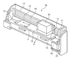
図1は、本発明の一実施の形態に係わる記録装置の内部構成を概略的に示す図である。
(Embodiment 1)
FIG. 1 is a diagram schematically showing an internal configuration of a recording apparatus according to an embodiment of the present invention.
インクジェット記録装置(以下、記録装置と呼ぶ)10は、インクジェット方式に従ってインクを吐出して記録を行なうインクジェット記録ヘッド(以下、記録ヘッドと呼ぶ)30をキャリッジ11に搭載する。そして、キャリッジ11をQ1及びQ2に示す方向(主走査方向)に往復移動させて記録を行なう。記録装置10は、記録紙などの記録媒体Pを記録開始位置まで搬送する。そして、その記録開始位置において、記録ヘッド30から記録媒体Pにインクを吐出することで記録を行なう。
An ink jet recording apparatus (hereinafter referred to as a recording apparatus) 10 has an ink jet recording head (hereinafter referred to as a recording head) 30 that performs recording by discharging ink in accordance with an ink jet method. Then, the
記録ヘッド30には、インクを吐出するためのノズルが1又は複数設けられる。なお、本実施形態においては、記録ヘッド30には、640個のノズルが色毎に設けられる。色毎に設けられる640個のノズルは、20分割して時分割駆動される。ここで、各ノズルには、発熱抵抗素子(以下、ヒータという)が設けられる。すなわち、本実施形態に係わる記録ヘッド30は、熱エネルギを利用してインクを吐出するタイプのインクジェット方式が採用される。
The
エンコーダフィルム14は、記録ヘッド30による記録タイミングの設定に使用される。光学式センサ15は、キャリッジ11の側面に配置されており、記録走査毎の記録媒体Pとの間の距離を測定するのに使用される。
The
搬送ローラ17は、主走査方向(Q1及びQ2に示す方向)と略直交する方向(Rに示す方向:副走査方向)に記録媒体Pを搬送する。プラテン18は、記録媒体Pを下方から支持する。
The
維持装置19は、記録ヘッド30のキャッピング、ヘッドのインク吐出面の払拭、更には記録ヘッドの回復動作等を行なう。キャップ20は、記録ヘッド30をキャッピングする。これにより、記録ヘッド30のノズルが密閉されるため、ノズル内のインクの乾燥を防ぐことができる。
The
以上の構成により、記録動作が開始されると、記録媒体Pは、給紙ローラ(不図示)によって給紙され、更に、搬送ローラ17によって所定の記録開始位置まで搬送される。この搬送ローラ17によって記録可能領域へと搬送された記録媒体Pは、その下方からプラテン18によって支持される。
With the above configuration, when the recording operation is started, the recording medium P is fed by a paper feed roller (not shown), and further conveyed by the
ここで、記録装置10は、キャリッジ11を主走査方向(矢印Q1及びQ2で示す方向)に往復移動させるとともに、キャリッジ11に搭載された記録ヘッド30のノズルからその下方に位置する記録媒体Pに向けてインクを吐出させる。これにより、1走査分の記録が行なわれる。
Here, the
1走査分の記録が終了すると、記録装置10は、搬送ローラ17によって記録媒体Pを副走査方向(Rに示す方向)に一定量だけ記録媒体Pを搬送し、上記同様に記録ヘッド30のノズルからインクを吐出させる。これらの記録媒体の搬送動作と記録ヘッドによる記録動作とを繰り返すことにより、記録が行なわれる。このとき、記録装置10は、キャリッジ11に搭載された光学式センサ15において、記録ヘッド30と記録媒体との間の距離を測定し、また、キャリッジ11に搭載されたエンコーダセンサ16において、エンコーダフィルム14上のスリットを読み取る。これにより、記録ヘッド30による記録タイミングが決められる。
When the recording for one scan is completed, the
次に、図2を用いて、図1に示す記録装置10における機能的な構成の一例について説明する。
Next, an example of a functional configuration of the
まず、外部装置1について説明する。外部装置1は、例えば、PC(Personal computer)やHDD(Hard disk drive)等であり、記録装置10に対して記録対象となる画像データを提供する役割を果たす。
First, the
続いて、記録装置10の構成について説明する。記録装置10には、記録装置10における処理を統括制御する制御回路40と、記録ヘッド30とが設けられる。記録ヘッド30には、記録ヘッド30の制御を行なうヘッド制御回路41と、1又は複数のヒータが配されるヒータボード44とが設けられる。ヒータボード44は、ヒータを駆動する駆動回路(不図示)を有する。
Next, the configuration of the
ここで、制御回路40には、CPU401と、SOC402と、DDR(Double-Data-Rate Synchronous Dynamic Random Access Memory)413と、電源回路414とが設けられる。
Here, the
電源回路414は、装置各部に電力を供給する。より具体的には、外部から入力された電力に対して電圧変換等を行なった後、記録装置10の各部に電力を供給する。例えば、ロジック回路動作用電力(VCC)、モータ駆動用電力(VM)、ヘッド駆動用電力(VH)等を生成する。
The
CPU401は、記録装置10における各部の動作を制御する。SOC402は、記録装置10特有のハードウェア制御を行なう。DDR413は、SOC402に外付けされる受信バッファである。DDR413には、例えば、画像処理された画像データが格納される。
The
SOC402には、外部I/F(Interface)回路403と、CPU I/F回路404と、メモリ制御回路405と、SRAM406と、画像データ処理回路407と、吐出画像生成回路408とが設けられる。また更に、SOC402には、ヒートパラメータ生成回路409、ヘッドI/F回路410、装置本体駆動回路411、吐出タイミング制御回路419も設けられる。
The
外部I/F回路403は、記録装置10と外部装置1との間の通信を司るインターフェースである。外部I/F回路403としては、例えば、USB(Universal Serial Bus) I/F回路、LAN(Local Area Network) I/F回路やIDE I/F回路などが挙げられる。
The external I /
CPU I/F回路404は、CPU(Central Processing Unit)に接続され、CPUと各構成との間の通信を司る。
The CPU I /
メモリ制御回路405は、SRAM406と各部との間の各種データの制御を行なう。メモリ制御回路405は、例えば、外部装置1から入力される画像データをSRAM406に転送する。また、メモリ制御回路405は、DDR413へのデータの読み出しや書き込み制御も行なう。
The
SRAM(Static Random Access Memory)406は、ワークバッファとして利用される。SRAM406には、例えば、画像データが特定サイズに分割されて格納される。このSRAMの個数は、色数分あっても良いし、また、ノズル数分あっても良く、適宜変更できる。
An SRAM (Static Random Access Memory) 406 is used as a work buffer. In the
画像データ処理回路407は、SRAM406に格納された画像データに対して画像処理を行なう。画像処理とは、例えば、HV変換やスムージング、不吐補完などの処理が挙げられるが、これに限られない。
The image
吐出画像生成回路408は、画像処理後の画像データを記録ヘッド30のノズルに合わせた形式のデータ(すなわち、吐出画像信号、以下、吐出画像データという)に変換する。ヒートパラメータ生成回路409は、記録ヘッド30のヒータを制御する吐出制御信号(ヒートパルス)のパラメータの生成(以下、ヒートパラメータという)を行なう。なお、ヒートパルスは、ヒータのヒート時間(発熱時間)を規定する信号である。ヒータは、ヒート時間に応じた電力VHが印加され、熱せられる。
The ejection
転送タイミング制御回路419は、吐出画像データ及びヒートパラメータ(以下、吐出画像データ及びヒートパラメータを加工した信号を画像信号という)の転送タイミングを示す信号(転送タイミング信号)を生成する。この信号は、エンコーダセンサ16により入力される信号を逓倍することにより生成される。
The transfer
ヘッドI/F回路410は、画像信号を処理し、基準となるクロック信号(以下、CLK信号という)と、吐出画像データを取り込むタイミングを指示する信号(以下、LAT信号という)と、画像信号とを記録ヘッド30(ヘッド制御回路41)へ転送する。これら信号の転送は、転送タイミング制御回路419により生成される転送タイミング信号に従って行なわれる。
The head I /
装置本体駆動回路411は、モータ412の駆動やセンサ(不図示)の制御を行なう。
The apparatus main
続いて、ヘッド制御回路41について説明する。ヘッド制御回路41は、ヘッド電源回路418と、電源制御回路42と、吐出制御回路43とを具備して構成される。
Next, the
電源制御回路42は、ヘッドI/F回路410により転送されてきた画像信号に基づいてヒータボード44への電力(VH)の供給のオンオフを制御する。電源制御回路42には、画像信号判定回路415と、電源制御信号生成回路417とが具備される。
The power
画像信号判定回路415は、ヘッドI/F回路410により転送されてきた画像信号が、正常であるか否かを判定する。正常でなければ、画像信号判定回路415は、電源制御信号生成回路417にアラート信号を出力する。ここで、正常でないデータとは、ヘッドI/F回路410と吐出信号生成回路416との間の転送において、ノイズの混入やデータ欠落などが生じたデータを指す。
The image
電源制御信号生成回路417は、ヘッドI/F回路410により転送されてきた画像信号のヒートパラメータに基づいてヘッド電源制御信号(以下、VH_ENBという)を生成する。また、電源制御信号生成回路417は、ヒートパラメータを解析し、有効なヒートパルスが転送されてきた場合は、VH_ENBをオンする。一方、電源制御信号生成回路417は、ヒートパルスに従って決められるヒート時間が規定よりも長い場合やノイズなどで想定のパルスと異なる場合は、VH_ENBをオフする。
The power supply control
ヘッド電源回路418は、電源制御信号生成回路417により出力されるVH_ENBの論理(オンオフ)に応じて電源回路414から出力されるVHのオンオフを切り替える。つまり、ヘッド電源回路418及び電源制御回路42は、電源回路414で生成された電力VHをヒータボードに供給する供給回路といえる。ヘッド電源回路418は、例えば、FET(field effect transistor)などで構成されることが望ましいが、そのような構成に限られない。
The head
吐出制御回路43は、ヘッドI/F回路410により転送されてきた画像信号に基づいて1又は複数のノズルからのインクの吐出を制御する。吐出制御回路43には、吐出信号生成回路416と、吐出信号保持回路420と、吐出タイミング調整回路421とが具備される。
The
吐出信号生成回路416は、ヘッドI/F回路410により転送されてきた画像信号を展開し、吐出画像データ及びヒートパルスを生成する。また、ヘッドI/F回路410により転送されてくるCLK信号及びLAT信号をヒータボード44に転送する。ヒータボード44に設けられた駆動回路(不図示)は、吐出画像データ及びヒートパルスに基づいてヒータを駆動する。
The ejection
吐出信号保持回路420は、吐出信号生成回路により生成された吐出画像データとヒートパルスとを(複数)保持する。なお、吐出信号保持回路420は、メモリアレイとポインタを有するFIFO(First In First Out)となっている(後述する図7参照)。
The ejection
吐出タイミング調整回路421は、エンコーダセンサ16により入力される信号を逓倍し、吐出タイミング信号を生成する。吐出タイミング調整回路421において、吐出位置と吐出データとの関係を調整し、規定のタイミングで吐出タイミング信号を吐出信号保持回路420に出力する。これにより、吐出信号保持回路420は、この信号に基づいて吐出画像データ及びヒートパルスをヒータボード44へ転送する。
The discharge
次に、図3を用いて、図1に示す記録装置10の動作の流れの一例について説明する。ここでは、インクを吐出するまでの処理の流れについて説明する。
Next, an example of the operation flow of the
記録装置10は、まず、外部I/F回路403において、外部装置1から画像データを受信する(S101)。そして、メモリ制御回路405において、当該受信した画像データをSRAM406に書き込む(S102)。
First, the
画像データがSRAM406に書き込まれると、記録装置10は、画像データ処理回路407において、当該画像データに対して画像処理を行なう(S103)。画像処理が済むと、記録装置10は、メモリ制御回路405において、画像処理後の画像データを特定単位(例えば、256bit)ずつ読み出す(S104)。そして、当該読み出した画像データ(256bitずつ)をDDR413に転送する(S105)。
When the image data is written in the
続いて、記録装置10は、吐出画像生成回路408において、DDR413に転送されたデータに基づいて、記録ヘッド30のノズルの形状に合わせた形式のデータ(吐出画像データ)を生成する(S106)。また、ヒートパラメータ生成回路409において、画像データや周囲温度やヘッド温度を加味してヒートパラメータを生成する(S107)。そして、ヘッドI/F回路410において、画像信号(吐出画像データ、ヒートパラメータ)をヘッド制御回路41へ転送する(S108)。
Subsequently, in the ejection
ここで、記録装置10は、画像信号判定回路415において、画像信号を解析し、当該画像信号が正常であるか否かを判定する。正常でなければ、電源制御信号生成回路417にアラート信号を出力する(S109)。
Here, the
続いて、記録装置10は、電源制御信号生成回路417において、ヘッドI/F回路410から転送されてきた画像信号のヒートパラメータに基づいて、電源制御信号VH_ENBを生成する(S110)。ここで、VH_ENBが”1”であり、電源回路414によりVHが印加されている場合、ヘッド電源回路418によりヒータボード44にVHが供給される(S111)。
Subsequently, in the power supply control
また、記録装置10は、吐出信号生成回路416において、ヘッドI/F回路410から転送されてきた画像信号を展開し(S112)、当該展開した画像信号を、吐出画像データ及びヒートパルスとして吐出信号保持回路420に転送する(S113)。そして、記録装置10は、吐出タイミング調整回路421において、吐出タイミング信号に従って、吐出信号保持回路420から吐出画像データ及びヒートパルスをヒータボード44に転送する(S114)。これにより、ヒータボード44における1又は複数のノズルからインクが吐出される(S115)。
The
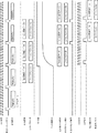
ここで、図4(a)〜図4(e)を用いて、吐出画像データと、ヒートパラメータと、画像信号との構成の一例について説明する。図4(a)は吐出画像データのビット構成の一例を示し、図4(b)はノズル列のイメージの一例を示し、図4(c)はヒートパラメータのビット構成の一例を示す。また、図4(d)はヒートパラメータにより生成されるヒートパルスの設定の一例を示し、図4(e)は画像信号のビット構成の一例を示す。 Here, an example of the configuration of the ejection image data, the heat parameter, and the image signal will be described with reference to FIGS. 4A to 4E. 4A shows an example of the bit configuration of the ejection image data, FIG. 4B shows an example of the image of the nozzle row, and FIG. 4C shows an example of the bit configuration of the heat parameter. FIG. 4D shows an example of setting a heat pulse generated by the heat parameter, and FIG. 4E shows an example of the bit configuration of the image signal.
本実施形態においては、上述した通り、記録ヘッド30には640個のノズルが色毎に設けられており、当該640個のノズルは、20個のブロックに分割して時分割駆動される。また、640個のノズルがどのように駆動されるかは、吐出画像生成回路408により制御される。
In this embodiment, as described above, the
吐出画像データは、図4(a)に示すように、ブロック番号5bit、ブロックデータ32bitの計37bitで構成される。ここで、吐出画像データについて、図4(b)に示すノズル列のイメージを用いて説明する。640個のノズルは、0〜19の20ブロックに分割される。各ブロックは、32個のノズルから構成される。吐出画像データのブロック番号5bitにおいて、0〜19のブロックが選択され、ブロックデータ32bitにおいて、あるブロックのいずれのノズルからインクが吐出されるかが選択される。
As shown in FIG. 4A, the ejection image data is composed of a total of 37 bits including a block number of 5 bits and block data of 32 bits. Here, the ejection image data will be described using the image of the nozzle row shown in FIG. 640 nozzles are divided into 20 blocks of 0-19. Each block is composed of 32 nozzles. In the
次に、ヒートパラメータについて説明する。ヒートパラメータ生成回路409により生成されるヒートパラメータは、図4(c)に示すビット構成で示される。具体的には、プレパルスON時間用7bit、インターバル時間用8bit、メインパルスON時間用8bit、ヒートパルスのON/OFF設定用1bitの計24bitで構成される。
Next, heat parameters will be described. The heat parameter generated by the heat
ここで、ヒートパルスがLOWアクティブであるとする。この場合、ヒートパルスは、図4(d)に示す構成となり、プレパルスON時間用7bitでプレパルス区間、インターバル時間用8bitでインターバル区間、メインパルスON時間用8bitでメインパルス区間が設定される。これにより、記録ヘッド30では、プレパルス及びメインパルスがオンされている期間の間、あるブロックのオンされているノズルのヒータのみ電圧が印加される。
Here, it is assumed that the heat pulse is LOW active. In this case, the heat pulse is configured as shown in FIG. 4D, and the prepulse interval is set to 7 bits for prepulse ON time, the interval interval is set to 8 bits for interval time, and the main pulse interval is set to 8 bits for main pulse ON time. Thereby, in the
次に、画像信号について説明する。画像信号は、図4(e)に示すビット構成で示される。画像信号は、ヘッドI/F回路410において、ヒートパラメータと、吐出画像データと、正誤判定用信号(正誤判定用データ)8bitとを含む計69bitの信号で構成される。画像信号は、制御回路40とヘッド制御回路41との接続を考慮した場合、シリアル転送されることが望ましい。シリアル転送される場合、LSBから順に転送される。
Next, the image signal will be described. The image signal is shown in the bit configuration shown in FIG. In the head I /
次に、画像信号判定回路415における画像信号の正誤判定について説明する。画像信号判定回路415は、画像信号に付加された正誤判定用信号8bitを用いて、画像信号の正誤判定を行なう。
Next, the correctness / incorrectness of the image signal in the image
ここで、正誤判定用信号は、固定値で設定され、例えば、”10101010”などとして画像信号に付加される。画像信号判定回路415は、ヘッドI/F回路410から画像信号が転送されてくる度に、正誤判定用信号が正しい値であるか否かを判定する。
Here, the correctness determination signal is set as a fixed value, and is added to the image signal as, for example, “10101010”. Each time the image signal is transferred from the head I /
この結果、正誤判定用信号が、正しい値を示していなければ、画像信号判定回路415は、電源制御信号生成回路417に向けてアラート信号を出力し、なんらかの理由により正しい画像信号が転送されていない旨を通知する。
As a result, if the correctness / incorrectness determination signal does not indicate a correct value, the image
なお、画像信号の正誤判定方法は、これに限られない。例えば、ヘッドI/F回路410から画像信号を受信した画像信号判定回路415において、ヘッドI/F回路410に再送を要求し、ヘッドI/F回路410において、信号の比較を行なうようにしても良い。この場合、ヘッドI/F回路410は、画像信号が正常であるか異常であるかの結果を画像信号判定回路415に向けて送信する。
Note that the image signal correctness determination method is not limited to this. For example, the image
図5は、図2に示す電源制御信号生成回路417における動作の流れの一例について説明する。ここでは、電源の制御処理の流れについて説明する。
FIG. 5 illustrates an example of an operation flow in the power supply control
ヘッドI/F回路410により画像信号(ヒートパラメータ)が転送されてくると(S201でNO)、電源制御信号生成回路417は、この処理を開始する。なお、画像信号が一定期間転送されてこない場合(S201でYES)、電源制御信号生成回路417は、記録動作が終了したと判定し、VH_ENBをオフする(S206)。すなわち、ヒータボード44へのVHの印加を切断する。
When the image signal (heat parameter) is transferred by the head I / F circuit 410 (NO in S201), the power supply control
また、画像信号が正常でなければ、電源制御信号生成回路417に対して画像信号判定回路415からアラート信号が入力される(S202でYES)。この場合、電源制御信号生成回路417は、VH_ENBをオフする(S206)。画像信号が正常である、すなわち、画像信号判定回路415からアラート信号が入力されていなければ(S202でNO)、電源制御信号生成回路417は、プレパルスON時間とメインパルスON時間との合計が所定時間以内であるかの判定を行なう。プレパルスON時間とメインパルスON時間との合計は、ヒータのオン期間を示す。なお、所定時間(最大印加時間Tmax)が設定されているのは、想定以上の長いパルスがヒータに印加されることによるヒータボード44の故障を防ぐためである。
If the image signal is not normal, an alert signal is input from the image
プレパルスON時間及びメインパルスON時間の合計時間が最大印加時間以上(所定時間以上)であれば(S203でNO)、電源制御信号生成回路417は、VH_ENBをオフする(S206)。そうでなければ(S203でYES)、電源制御信号生成回路417は、ヒートパラメータのヒートパルスONの設定を確認する。なお、ヒートパルスONの場合は、当該ヒートパラメータが有効であることを示し、ヒートパルスOFFの場合は、当該ヒートパラメータが無効であることを示す。
If the total time of the pre-pulse ON time and the main pulse ON time is equal to or longer than the maximum application time (predetermined time) (NO in S203), the power supply control
ここで、ヒートパルスON=”1”であれば(S204でYES)、電源制御信号生成回路417は、VH_ENBをオンする(S205)。また、ヒートパルスON=”0”であれば(S204でNO)、電源制御信号生成回路417は、VH_ENBをオフする(S206)。なお、ヒートパルスON=”0”が入力される場合としては、装置本体の駆動部、例えば、キャリッジ11で異常が発生し、VHを即座に切断する必要性が生じている等が考えられる。
If the heat pulse is ON = “1” (YES in S204), the power supply control
このように電源制御信号生成回路417においては、画像信号と同期してVH_ENBを制御する。これにより、様々な状況に対応してVHを即座に切断することができる。
図6は、図1に示す記録装置10における画像信号の処理タイミングの一例を示す図である。ここでは、ヘッドI/F回路410から、吐出画像データ及びヒートパラメータが記録ヘッド30に転送されるまでのタイミングについて説明する。
Thus, the power control
FIG. 6 is a diagram illustrating an example of processing timing of an image signal in the
なお、VH_ENBがオンされてから、VHが所定電圧に達し安定するまでには、多少の時間を要する。この時間は、VHの電圧や回路構成に応じて異なってくるため、ここでは、転送タイミング信号1周期分であるとする。この場合、VHの電圧が安定するまで転送タイミング信号1周期分かかるため、吐出タイミングよりも1周期以上早いタイミング(VHの電圧が安定するまでに要する時間以上前のタイミング)で画像信号をヘッド制御回路41に送ることでタイミングの調整を行なう。
Note that it takes some time for VH to reach a predetermined voltage and stabilize after VH_ENB is turned on. Since this time varies depending on the voltage of VH and the circuit configuration, it is assumed here that it is for one cycle of the transfer timing signal. In this case, since it takes one cycle of the transfer timing signal until the VH voltage is stabilized, the head control of the image signal is performed at a timing that is one cycle or more earlier than the ejection timing (timing before the time required for the VH voltage to stabilize). The timing is adjusted by sending it to the
ここで、まず、転送タイミング制御回路419において、エンコーダ信号をN逓倍した転送タイミング信号を出力し、ヘッドI/F回路410において、そのタイミングに応じて画像信号を記録ヘッド30側にシリアル転送する。ここでは、t1のタイミングで画像信号1がシリアル転送されている。
First, the transfer
ヘッドI/F回路410からシリアル転送された画像信号1は、吐出信号生成回路416において、t2のタイミングでラッチされ、吐出画像データ1及びヒートパラメータ1が生成される。転送タイミングの信号周期よりも、画像信号の方が明らかに小さいため、t3のタイミングよりも前に、吐出画像データ1及びヒートパラメータ1の生成は完了する。
The
画像信号に異常がなければ、電源制御信号生成回路417は、次の転送タイミング信号のタイミング(t3のタイミング)でVH_ENBをオンする。これにより、ヘッド電源回路418から記録ヘッド30にVHが供給される。
If there is no abnormality in the image signal, the power supply control
また、吐出信号保持回路420は、t3のタイミングにおいて、吐出信号生成回路416により生成された吐出画像データ1及びヒートパラメータ1を保持する。この吐出画像データ1及びヒートパラメータ1は、吐出タイミング調整回路421より送信される吐出タイミング信号に応じて、記録ヘッド30側に転送される。
Further, the ejection
その後、記録ヘッド30に転送された吐出画像データ及びヒートパルスに基づいて、ヒータボード44に形成された1又は複数のノズルからインクが吐出される。このインクの吐出は、CLK信号及びLAT信号のタイミングに従って行なわれる。
Thereafter, ink is ejected from one or a plurality of nozzles formed on the
ここで、吐出信号保持回路420は、図7に示すように、メモリアレイとポインタとを有するFIFOとなっている。VH_ENBがオンされ、転送タイミング信号が入力された場合、吐出信号生成回路416により生成された吐出画像データ及びヒートパラメータがメモリアレイに格納される。そして、吐出タイミング調整回路421から吐出タイミング信号が入力されると、メモリアレイに格納されていた吐出画像データと、ヒートパラメータが記録ヘッド30側へ転送される。メモリアレイの段数によって、吐出信号を保持する数を調整できる。
Here, the ejection
ここでは、VHの電圧が安定するまでの転送タイミング1周期として説明したが、VHの電圧が安定するよりも前に画像信号を記録ヘッド30(ヘッド制御回路41)に転送するように構成しても良い。この場合、吐出信号保持回路420において、吐出信号生成回路416により生成された画像信号を(複数)保持する。このように構成した場合であっても、吐出信号保持回路420においては、古い信号から順に記録ヘッド30側に画像信号を転送できるので、VHの安定時間に関係なく、上述した処理を実現できる。
Here, the transfer timing until the VH voltage is stabilized has been described as one cycle. However, the image signal is transferred to the recording head 30 (head control circuit 41) before the VH voltage is stabilized. Also good. In this case, the discharge
また、上述した説明では、VHの電圧が安定するまでのタイミングを調整するために、電圧が安定する時間から逆算して求めたタイミングで、画像信号を記録ヘッド30(ヘッド制御回路41)に転送する場合について説明したが、これに限られない。例えば、ダミーの吐出画像データ及びヒートパラメータ(インクの吐出なし)をヘッド制御回路41側に転送することで実際に記録動作を開始するよりも前にVHをオンする手法も考えられる。
In the above description, in order to adjust the timing until the voltage of VH is stabilized, the image signal is transferred to the recording head 30 (head control circuit 41) at a timing obtained by calculating backward from the time when the voltage is stabilized. However, the present invention is not limited to this. For example, a method of turning on VH before actually starting the recording operation by transferring dummy ejection image data and heat parameters (no ink ejection) to the
以上説明したように本実施形態によれば、記録ヘッド側において、画像信号(吐出画像データ、ヒートパラメータ)に基づいてVHのオンオフを制御できる。これにより、記録ヘッド30によりインクが吐出される直前にVHを印加できるため、消費電力を低減できる。また、記録ヘッド側において、イリーガルな画像が入力された場合や、一定期間の間、画像信号が入力されない場合であっても、VHを効率的に制御できる。
As described above, according to the present embodiment, on / off of VH can be controlled on the recording head side based on image signals (discharged image data, heat parameters). Thereby, since VH can be applied immediately before ink is ejected by the
(実施形態2)
次に、実施形態2について説明する。実施形態1においては、画像信号に応じてVHのオンオフ制御を行なう構成について説明したが、実施形態2においては、画像信号に応じてVHの電圧の制御を行なう場合について説明する。なお、記録装置10の構成、データ構成や処理の流れについては実施形態1と同様であるため、ここでは、相違する点について重点的に説明する。
(Embodiment 2)
Next,
図8は、実施形態2に係わる記録装置10における機能的な構成の一例について説明する。なお、実施形態1で説明した図2の構成と同様の構成については同一の符号を付してあり、その説明については省略する場合もある。
FIG. 8 illustrates an example of a functional configuration of the
ここで、実施形態2に係わるヘッド制御回路41の内部に設けられるヘッド電源回路418は、ヘッド電圧生成回路として機能し、複数段階(例えば、64段階)の電圧を生成可能に構成される。より具体的には、ヘッド電圧選択信号生成回路501からのヘッド電圧選択信号に応じて電源回路414から供給されるVHの電圧を切り替える。実施形態2に係わるヘッド電源回路418は、例えば、DC/DCコンバータなどで構成されることが望ましいが、そのような構成に限られない。
Here, the head
また、ヘッド制御回路41の内部には、ヘッド電圧選択信号生成回路501が新たに設けられる。ヘッド電圧選択信号生成回路501は、ヘッドI/F回路410により転送されてきた画像信号に基づいてヘッド駆動用電力(VH)の電圧を選択する。そして、その結果としてヘッド電圧選択信号をヘッド電源回路418に向けて出力する。これにより、実施形態2に係わるヘッド制御回路41においては、画像信号に基づいてVHの電圧を動的に変更できる。
In addition, a head voltage selection
ここで、例えば、実施形態1において、ヒータボード44に対してVHの供給をオフしていたときには、実施形態2においては、ノズルからインクが吐出されないレベルの電圧値を持つVHをヒータボードに供給する。また、実施形態1において、ヒータボード44に対してVHの供給をオンしていたときには、実施形態2においては、VHの電圧値をノズルからインクが吐出されるレベルにする。なお、詳細については後述するが、VHの電圧値をノズルからインクが吐出されるレベルにする場合、画像信号に含まれる吐出画像データにより吐出が指示されるノズルの数(ドットカウント値)に基づいてVHの電圧値が決定される。
Here, for example, in the first embodiment, when the supply of VH to the
なお、実施形態2に係わる記録装置10においてインクを吐出する際の処理は、実施形態1を説明した図3に示す流れと同様となるため、ここでは図を用いた説明については省略する。実施形態1と相違する点について簡単に説明すると、S110の処理において、ヘッド電圧選択信号生成回路501が、ヘッドI/F回路410から転送されてきた画像信号に基づいてヘッド電圧選択信号を生成する。そして、S111の処理において、ヘッド電源回路418が、電源回路414によりVHが印加されている間、ヘッド電圧選択信号により選択された電圧値を持つVHをヒータボード44に印加する。
In addition, since the process when ejecting ink in the
次に、図9(a)を用いて、図8に示すヘッド電圧選択信号生成回路501における機能的な構成の一例について説明する。
Next, an example of a functional configuration in the head voltage selection
ヘッド電圧選択信号生成回路501には、図9(a)に示すように、吐出画像データラッチ回路511と、ドットカウント回路512と、ヘッド電圧選択回路513とが設けられる。
As shown in FIG. 9A, the head voltage selection
ヘッド電圧選択信号生成回路501における処理が開始すると、まず、吐出画像データラッチ回路511において、ヘッドI/F回路410から転送されてきた画像信号をラッチし、吐出画像データを生成する。吐出画像データは、実施形態1を説明した図4(a)に示すように、ブロック番号とブロックデータとから構成される。上述した通り、このブロックデータのドット数(吐出が指示されるノズルの数)の合計が1回に吐出されるドット数となる。
When the processing in the head voltage selection
続いて、ドットカウント回路512において、ブロックデータのドット数をカウントする(以下、カウントされたドット数をドットカウント値という)。ドットカウント値は、ヘッド電圧選択回路513に出力される。
Subsequently, the
ここで、ヘッド電圧選択回路513の内部には、ドットカウント値とVHの電圧とが関連付けられたテーブルが設けられる。このテーブルは、ソフト的に変更可能となっている。ヘッド電圧選択回路513は、このテーブルに基づいて、ドットカウント回路512からのドットカウント値に応じたヘッド電圧選択信号をヘッド電源回路418に出力する。例えば、ドットカウント値が大きい場合には、ヒータボード44に供給するVHの電圧値を大きくすれば良い。
Here, a table in which the dot count value and the voltage of VH are associated is provided in the head
なお、上述した説明では、VHの決定に用いられるドットカウント値は、1回の吐出画像データの合計としたが、これに限られない。すなわち、図9(b)に示すように、ドットカウント加算回路514を設け、複数回分のドットカウント値に基づいてVHの電圧を変更するように構成しても良い。
In the above description, the dot count value used to determine VH is the total of one ejection image data, but is not limited thereto. That is, as shown in FIG. 9B, a dot
ここで、ヘッド電圧選択信号は、図9(c)に示すように、6bitで構成される。そのため、例えば、64段階の電圧の変更が可能となっている。 Here, the head voltage selection signal is composed of 6 bits as shown in FIG. For this reason, for example, the voltage can be changed in 64 steps.
次に、図10を用いて、図8に示すヘッド電圧選択信号生成回路501における動作の流れの一例について説明する。ここでは、電源の制御処理の流れについて説明する。なお、S301〜S304の処理は、実施形態1で図5を用いて説明した電源制御信号生成回路417におけるS201〜S204の処理と同様であるため、ここではその説明については省略する。なお、S307の処理では、ノズルからインクが吐出されないレベルの電圧値の一例としてVHを0Vとしているが、これは、実質的に、VH_ENBのオフと同じ意味を示す。
Next, an example of the operation flow in the head voltage selection
ここで、S304において、ヒートパルスON=”1”であれば(S304でYES)、ヘッド電圧選択信号生成回路501は、その内部テーブルに基づいて、吐出画像データのドットカウント値に応じた電圧を選択する(S305)。そして、ヘッド電圧選択信号生成回路501は、ヘッド電源回路418に向けてヘッド電圧選択信号を出力する(S306)。
Here, if the heat pulse is ON = “1” in S304 (YES in S304), the head voltage selection
以上説明したように実施形態2によれば、記録ヘッド側において、画像信号(吐出画像データ、ヒートパラメータ)に基づいてVHの電圧(電圧値)を動的に制御できる。これにより、記録ヘッド側において、イリーガルな画像が入力された場合や、一定期間の間、画像信号が入力されない場合であっても、VHを効率的に制御できる。 As described above, according to the second embodiment, the voltage (voltage value) of VH can be dynamically controlled on the recording head side based on the image signal (discharged image data, heat parameter). Accordingly, VH can be efficiently controlled even when an illegal image is input on the recording head side, or even when an image signal is not input for a certain period.
なお、従来の構成では、VHを可変に制御できる電源回路を有していたとしても、記録ヘッド側で吐出画像データの開始や終了を判定することができなかったため、VHが印加されない期間の間に、VHを変更する必要があった。そのため、画像信号に応じて動的にVHの電圧を変更することは困難であった。 In the conventional configuration, even if the power supply circuit capable of variably controlling the VH is provided, the start or end of the ejection image data cannot be determined on the recording head side. Therefore, during the period in which the VH is not applied. In addition, it was necessary to change VH. For this reason, it has been difficult to dynamically change the voltage of VH according to the image signal.
以上が本発明の代表的な実施形態の例であるが、本発明は、上記及び図面に示す実施形態に限定することなく、その要旨を変更しない範囲内で適宜変形して実施できるものである。 The above is an example of a typical embodiment of the present invention, but the present invention is not limited to the embodiment described above and shown in the drawings, and can be appropriately modified and implemented within the scope not changing the gist thereof. .
Claims (12)
インクを吐出するノズルに対応して設けられた複数のヒータ及び各ヒータを駆動する駆動回路を含むヒータボードを有するプリントヘッドと、
前記受信手段により受信した画像データに基づいて、画像を印刷するための吐出画像データ及び前記ヒータを制御するための制御データを生成する生成手段と、
前記生成手段により生成された吐出画像データ及び制御データを含む画像信号を転送する転送手段と、
前記転送手段により転送された画像信号から得られる吐出画像データ及び制御データを前記ヒータボードに所定のタイミングで転送することにより、前記ヒータボードの前記駆動回路を制御する吐出制御手段と、
前記ヒータボードへ電力を供給するヒータボード電源回路と、
前記転送手段により転送された画像信号が所定の条件を満たしているか否かに基づいて、前記ノズルからインクを吐出させるレベルの電力を前記ヒータボード電源回路により前記ヒータボードに対して供給させるか否かを制御する電源制御手段と、を有し、
前記プリントヘッドは、前記吐出制御手段と前記ヒータボード電源回路と前記電源制御手段とを有する
ことを特徴とする印刷装置。 Receiving means for receiving image data;
A print head having a heater board including a plurality of heaters provided corresponding to nozzles that eject ink and a drive circuit that drives each heater;
Generating means for generating ejection image data for printing an image and control data for controlling the heater based on the image data received by the receiving means;
Transfer means for transferring an image signal including ejection image data and control data generated by the generation means;
Discharge control means for controlling the drive circuit of the heater board by transferring discharge image data and control data obtained from the image signal transferred by the transfer means to the heater board at a predetermined timing ; and
A heater board power supply circuit for supplying power to the heater board;
Whether or not to supply power to the heater board by the heater board power supply circuit based on whether or not the image signal transferred by the transfer means satisfies a predetermined condition. and power control means for controlling whether or not, have a,
It said print head to a printing apparatus, characterized by chromatic and said ejection control means and the heater board power supply circuit and the power supply control unit.
第1の転送タイミング信号のタイミングで、前記転送手段は画像信号を転送し、At the timing of the first transfer timing signal, the transfer means transfers the image signal,
第2の転送タイミング信号のタイミングで、前記吐出制御手段は、前記転送手段から転送された画像信号から吐出画像データ及び制御データを取得し、At the timing of the second transfer timing signal, the discharge control means acquires discharge image data and control data from the image signal transferred from the transfer means,
第3の転送タイミング信号のタイミングで、前記電源制御手段は、前記ノズルからインクを吐出させるレベルの電力を前記ヒータボード電源回路により前記ヒータボードに対して供給させるか否かを制御し、At the timing of the third transfer timing signal, the power control means controls whether or not the heater board power supply circuit supplies power to the heater board at a level at which ink is ejected from the nozzles.
前記第3の転送タイミング信号のタイミングの後に、前記吐出制御手段は、前記第2の転送タイミング信号のタイミングで取得された吐出画像データ及び制御データを前記ヒータボードに転送するAfter the timing of the third transfer timing signal, the discharge control means transfers the discharge image data and control data acquired at the timing of the second transfer timing signal to the heater board.
ことを特徴とする請求項1に記載の印刷装置。The printing apparatus according to claim 1.
ことを特徴とする請求項1又は請求項2に記載の印刷装置。 Said ejection control means, based on the discharge image data and control data generated by expanding the image signal transferred by said transfer means, according to claim 1 or claim, characterized in that controlling the ink from the nozzle The printing apparatus according to 2 .
ことを特徴とする請求項1から請求項3のいずれか1項に記載の印刷装置。 The printing apparatus according to claim 1 , wherein the discharge control unit, the heater board power supply circuit, and the power supply control unit are provided in the print head.
ことを特徴とする請求項1から請求項4のいずれか1項に記載の印刷装置。 The power supply control means controls power supply to the heater board by the heater board power supply circuit based on whether or not the image signal transferred by the transfer means is normal. The printing apparatus according to claim 4 .
ことを特徴とする請求項5に記載の印刷装置。 Image signal said transfer means for transferring further comprises a right or wrong decision signal, said power supply control means to claim 5, wherein the determining whether the image signal is normal based on the positive erroneous determination signal The printing apparatus as described.
ことを特徴とする請求項1から請求項6のいずれか1項に記載の印刷装置。 The image signal transferred by the transfer means further includes information for specifying whether or not the control data is valid, and the power supply control means supplies the heater board to the heater board based on the information. The printing apparatus according to any one of claims 1 to 6 , wherein power supply is controlled.
ことを特徴とする請求項1から請求項7のいずれか1項に記載の印刷装置。 The power control means supplies power to the heater board by the heater board power circuit based on whether or not the heater ON time indicated by the control data of the image signal transferred by the transfer means is within a predetermined time. The printing apparatus according to any one of claims 1 to 7 , wherein the printing apparatus is controlled.
ことを特徴とする請求項1から請求項8のいずれか1項に記載の印刷装置。 Said power supply control means is any one of claims 1 to 8, characterized in that for controlling the supply of power on / off of the heater board power supply circuit in accordance with the image signal transferred by said transfer means The printing apparatus as described in.
ことを特徴とする請求項9に記載の印刷装置。 The power control means determines whether or not the voltage value of the power supplied by the heater board power supply circuit is a voltage value at a level at which ink is ejected from the nozzles in accordance with the image signal transferred by the transfer means. the printing apparatus according to claim 9, characterized in that control.
ことを特徴とする請求項1から請求項10のいずれか1項に記載の印刷装置。 The printing apparatus according to any one of claims 1 to 10, wherein the transfer unit further transfers a dummy image signal including a dummy discharge signal that does not cause ink to be discharged from the nozzle.
画像データを受信する受信工程と、
前記受信工程において受信した画像データに基づいて、画像を印刷するための吐出画像データ及び前記ヒータを制御するための制御データを生成する生成工程と、
前記生成工程において生成された吐出画像データ及び制御データを含む画像信号を転送する転送工程と、
前記転送工程において転送された画像信号から得られる吐出画像データ及び制御データを前記ヒータボードに所定のタイミングで転送することにより、前記ヒータボードの前記駆動回路を制御する吐出制御工程と、
前記転送工程において転送された画像信号が所定の条件を満たしているか否かに基づいて、前記ノズルからインクを吐出させるレベルの電力を前記ヒータボード電源回路により前記ヒータボードに対して供給させるか否かを制御する電源制御工程と、
前記ヒータボード電源回路により前記ヒータボードへ電力を供給する電力供給工程と、を有する
ことを特徴とする制御方法。
A printing apparatus comprising: a heater board including a plurality of heaters provided corresponding to nozzles that eject ink; a drive circuit that drives each heater; and a heater board power supply circuit that supplies power to the heater board. Control method,
A receiving process for receiving image data;
Based on the image data received in the reception step, a generation step for generating ejection image data for printing an image and control data for controlling the heater;
A transfer step of transferring an image signal including the ejection image data and the control data generated in the generation step;
A discharge control step of controlling the drive circuit of the heater board by transferring the discharge image data and control data obtained from the image signal transferred in the transfer step to the heater board at a predetermined timing ;
Whether or not to supply power to the heater board by the heater board power supply circuit based on whether or not the image signal transferred in the transfer step satisfies a predetermined condition. a power supply control step of controlling whether,
Control method characterized by having a power supply step of supplying power to the heater board by the heater board power supply circuit.
Priority Applications (1)
| Application Number | Priority Date | Filing Date | Title |
|---|---|---|---|
| JP2012045789A JP5997461B2 (en) | 2011-03-09 | 2012-03-01 | Recording device |
Applications Claiming Priority (3)
| Application Number | Priority Date | Filing Date | Title |
|---|---|---|---|
| JP2011052119 | 2011-03-09 | ||
| JP2011052119 | 2011-03-09 | ||
| JP2012045789A JP5997461B2 (en) | 2011-03-09 | 2012-03-01 | Recording device |
Publications (3)
| Publication Number | Publication Date |
|---|---|
| JP2012196961A JP2012196961A (en) | 2012-10-18 |
| JP2012196961A5 JP2012196961A5 (en) | 2015-04-16 |
| JP5997461B2 true JP5997461B2 (en) | 2016-09-28 |
Family
ID=46795155
Family Applications (1)
| Application Number | Title | Priority Date | Filing Date |
|---|---|---|---|
| JP2012045789A Expired - Fee Related JP5997461B2 (en) | 2011-03-09 | 2012-03-01 | Recording device |
Country Status (2)
| Country | Link |
|---|---|
| US (1) | US9272509B2 (en) |
| JP (1) | JP5997461B2 (en) |
Families Citing this family (3)
| Publication number | Priority date | Publication date | Assignee | Title |
|---|---|---|---|---|
| JP6417129B2 (en) * | 2014-07-02 | 2018-10-31 | 株式会社東芝 | Ink jet head unit and method for controlling ink jet head |
| JP6414490B2 (en) * | 2015-03-06 | 2018-10-31 | ブラザー工業株式会社 | Image forming system |
| JP6907517B2 (en) * | 2016-11-30 | 2021-07-21 | ブラザー工業株式会社 | Image recording device |
Family Cites Families (38)
| Publication number | Priority date | Publication date | Assignee | Title |
|---|---|---|---|---|
| US4651173A (en) | 1984-05-19 | 1987-03-17 | Canon Kabushiki Kaisha | Continuous-form recorder having decrumpling means for removing creases in the form |
| US5355160A (en) | 1984-05-19 | 1994-10-11 | Canon Kabushiki Kaisha | Recorder having separate recording means and feeding means housings |
| US4922267B1 (en) | 1984-05-19 | 1995-04-11 | Canon Kk | Recorder having a recording device and a relatively movable stacker for stacking recorded paper. |
| US4692778A (en) | 1985-03-28 | 1987-09-08 | Canon Kabushiki Kaisha | Image formation apparatus with a recording unit and paper feed cover and a sealing member |
| US5262872A (en) | 1985-03-28 | 1993-11-16 | Canon Kabushiki Kaisha | Image forming apparatus with means for error detection |
| US5223859A (en) | 1985-03-28 | 1993-06-29 | Canon Kabushiki Kaisha | Image formation apparatus with means for capping a recording head assembly |
| JPS62160255A (en) | 1986-01-09 | 1987-07-16 | Canon Inc | Printing head protection circuit |
| JPH0811447B2 (en) | 1986-03-20 | 1996-02-07 | キヤノン株式会社 | Image forming device |
| JP3026978B2 (en) | 1988-10-07 | 2000-03-27 | キヤノン株式会社 | Recording device |
| EP0424968B1 (en) | 1989-10-27 | 1996-07-03 | Canon Kabushiki Kaisha | Sheet feeding apparatus |
| EP0442484B1 (en) | 1990-02-13 | 1997-07-30 | Canon Kabushiki Kaisha | A recording apparatus |
| EP0526209B1 (en) | 1991-07-31 | 1997-11-05 | Canon Kabushiki Kaisha | Drive transmission mechanism for recording apparatus |
| JP2875915B2 (en) | 1991-08-02 | 1999-03-31 | キヤノン株式会社 | Recording device |
| US5480247A (en) | 1992-05-29 | 1996-01-02 | Canon Kabushiki Kaisha | Sheet supplying apparatus |
| US6065830A (en) | 1992-09-18 | 2000-05-23 | Canon Kabushiki Kaisha | Recording apparatus for recording at different recording speeds |
| JP3126277B2 (en) | 1993-09-08 | 2001-01-22 | キヤノン株式会社 | Recording device |
| JP3495804B2 (en) | 1994-01-25 | 2004-02-09 | キヤノン株式会社 | Recording medium transport mechanism and ink jet recording apparatus using the mechanism |
| JP3437319B2 (en) | 1994-04-05 | 2003-08-18 | キヤノン株式会社 | Ink jet recording apparatus and ink jet image forming method |
| JP3402767B2 (en) | 1994-07-29 | 2003-05-06 | キヤノン株式会社 | Recording apparatus and control method for recording apparatus |
| JP3374608B2 (en) | 1994-08-04 | 2003-02-10 | キヤノン株式会社 | Information processing apparatus and head member attachable to the information processing apparatus |
| JP3359205B2 (en) | 1994-11-25 | 2002-12-24 | キヤノン株式会社 | Recording device |
| US6027212A (en) | 1995-04-21 | 2000-02-22 | Canon Kabushiki Kaisha | Switching mechanism and a recording apparatus using said switching mechanism |
| US6260950B1 (en) | 1995-04-21 | 2001-07-17 | Canon Kabushiki Kaisha | Ink jet printing system using printers with interchangeable printing units |
| EP0890439A3 (en) | 1997-07-11 | 1999-08-25 | Lexmark International, Inc. | Ink jet printhead with an integral substrate heater driver |
| JP3311284B2 (en) * | 1997-10-24 | 2002-08-05 | キヤノン株式会社 | Liquid discharge recording head, liquid discharge recording method, and liquid discharge recording apparatus |
| JP2001232772A (en) | 2000-02-18 | 2001-08-28 | Seiko Epson Corp | Ink-jet recording apparatus |
| US6508533B2 (en) | 2000-03-28 | 2003-01-21 | Canon Kabushiki Kaisha | Ink-jet printing apparatus and recovery processing method of ejection port |
| JP4186151B2 (en) | 2001-03-08 | 2008-11-26 | セイコーエプソン株式会社 | Liquid ejector |
| JP4266588B2 (en) * | 2002-07-30 | 2009-05-20 | キヤノン株式会社 | Recording apparatus and recording control method |
| JP3927902B2 (en) * | 2002-11-29 | 2007-06-13 | キヤノン株式会社 | Inkjet recording head, inkjet recording apparatus having the recording head, and substrate for inkjet recording head |
| JP4356070B2 (en) * | 2003-04-02 | 2009-11-04 | セイコーエプソン株式会社 | Liquid ejector |
| JP2006212823A (en) | 2005-02-01 | 2006-08-17 | Canon Inc | Recording apparatus and control method for recording head |
| JP2007018375A (en) | 2005-07-08 | 2007-01-25 | Canon Inc | Printer, printing controller, printing control method, and printer control program |
| JP5107513B2 (en) * | 2005-09-05 | 2012-12-26 | 大日本スクリーン製造株式会社 | Printing method and printing apparatus |
| JP2009028928A (en) * | 2007-07-25 | 2009-02-12 | Rohm Co Ltd | Thermal printing head |
| KR101186163B1 (en) * | 2007-08-24 | 2012-10-02 | 삼성전자주식회사 | Ink jet image forming apparatus and control method thereof |
| JP2009220287A (en) | 2008-03-13 | 2009-10-01 | Fujifilm Corp | Liquid droplet ejection device, liquid droplet ejection system, and liquid droplet ejection method |
| JP5094564B2 (en) * | 2008-06-02 | 2012-12-12 | キヤノン株式会社 | Recording device |
-
2012
- 2012-02-27 US US13/405,586 patent/US9272509B2/en not_active Expired - Fee Related
- 2012-03-01 JP JP2012045789A patent/JP5997461B2/en not_active Expired - Fee Related
Also Published As
| Publication number | Publication date |
|---|---|
| JP2012196961A (en) | 2012-10-18 |
| US20120229538A1 (en) | 2012-09-13 |
| US9272509B2 (en) | 2016-03-01 |
Similar Documents
| Publication | Publication Date | Title |
|---|---|---|
| JP4262070B2 (en) | Element base of recording head, recording head, and control method of recording head | |
| JP2008162275A (en) | Head substrate, recording head, head cartridge, and recorder | |
| JP2008162268A (en) | Head substrate, recording head, head cartridge, and recorder | |
| JP2008279616A (en) | Recorder and method for generating clock | |
| JP2005074944A (en) | Device and method of recording | |
| JP5997461B2 (en) | Recording device | |
| JP6141032B2 (en) | Recording element substrate, recording head, and recording apparatus | |
| JP4785375B2 (en) | Inkjet recording head substrate, recording head, head cartridge, and recording apparatus | |
| JP2005047093A (en) | Recording head substrate, recording head, and recording device | |
| JP6649694B2 (en) | Recording apparatus and recording control method | |
| JP5017202B2 (en) | Recording head and recording apparatus using the recording head | |
| JP4799389B2 (en) | Head substrate, recording head, head cartridge, and recording apparatus | |
| JP5383210B2 (en) | Recording device | |
| JP2011235528A (en) | Recording head and recording apparatus | |
| JP5451042B2 (en) | Recording head and recording apparatus | |
| JP2002321342A (en) | Printing device | |
| JP2007156560A (en) | Information processing system, recorder, and access control method | |
| JP2005169867A (en) | Recording head element substrate, recording head and recording device | |
| JP2021181220A (en) | Method for transmitting printing data and printer | |
| JP2013193280A (en) | Recording apparatus | |
| JP2006159574A (en) | Recording head, head cartridge, recording head driving method, and recorder | |
| JP2009125943A (en) | Head for discharging liquid, its controlling method, and recorder | |
| JP2018024230A (en) | Element substrate, recording head, and recording apparatus | |
| JP2019084685A (en) | Recording device and recording control method | |
| JP2005225010A (en) | Recording device |
Legal Events
| Date | Code | Title | Description |
|---|---|---|---|
| A521 | Written amendment |
Free format text: JAPANESE INTERMEDIATE CODE: A523 Effective date: 20150227 |
|
| A621 | Written request for application examination |
Free format text: JAPANESE INTERMEDIATE CODE: A621 Effective date: 20150227 |
|
| A977 | Report on retrieval |
Free format text: JAPANESE INTERMEDIATE CODE: A971007 Effective date: 20151216 |
|
| A131 | Notification of reasons for refusal |
Free format text: JAPANESE INTERMEDIATE CODE: A131 Effective date: 20151222 |
|
| A521 | Written amendment |
Free format text: JAPANESE INTERMEDIATE CODE: A523 Effective date: 20160222 |
|
| TRDD | Decision of grant or rejection written | ||
| A01 | Written decision to grant a patent or to grant a registration (utility model) |
Free format text: JAPANESE INTERMEDIATE CODE: A01 Effective date: 20160729 |
|
| A61 | First payment of annual fees (during grant procedure) |
Free format text: JAPANESE INTERMEDIATE CODE: A61 Effective date: 20160826 |
|
| R151 | Written notification of patent or utility model registration |
Ref document number: 5997461 Country of ref document: JP Free format text: JAPANESE INTERMEDIATE CODE: R151 |
|
| LAPS | Cancellation because of no payment of annual fees |