JP5997102B2 - Liquid discharge head and recording apparatus using the same - Google Patents

Liquid discharge head and recording apparatus using the same Download PDF

Info

Publication number
JP5997102B2
JP5997102B2 JP2013113097A JP2013113097A JP5997102B2 JP 5997102 B2 JP5997102 B2 JP 5997102B2 JP 2013113097 A JP2013113097 A JP 2013113097A JP 2013113097 A JP2013113097 A JP 2013113097A JP 5997102 B2 JP5997102 B2 JP 5997102B2
Authority
JP
Japan
Prior art keywords
flow path
gap
liquid discharge
individual
pressurizing chamber
Prior art date
Legal status (The legal status is an assumption and is not a legal conclusion. Google has not performed a legal analysis and makes no representation as to the accuracy of the status listed.)
Active
Application number
JP2013113097A
Other languages
Japanese (ja)
Other versions
JP2014231183A (en
JP2014231183A5 (en
Inventor
由宇 喜裕
喜裕 由宇
Current Assignee (The listed assignees may be inaccurate. Google has not performed a legal analysis and makes no representation or warranty as to the accuracy of the list.)
Kyocera Corp
Original Assignee
Kyocera Corp
Priority date (The priority date is an assumption and is not a legal conclusion. Google has not performed a legal analysis and makes no representation as to the accuracy of the date listed.)
Filing date
Publication date
Application filed by Kyocera Corp filed Critical Kyocera Corp
Priority to JP2013113097A priority Critical patent/JP5997102B2/en
Publication of JP2014231183A publication Critical patent/JP2014231183A/en
Publication of JP2014231183A5 publication Critical patent/JP2014231183A5/ja
Application granted granted Critical
Publication of JP5997102B2 publication Critical patent/JP5997102B2/en
Active legal-status Critical Current
Anticipated expiration legal-status Critical

Links

Images

Description

本発明は、液滴を吐出させる液体吐出ヘッド、およびそれを用いた記録装置に関する。   The present invention relates to a liquid discharge head that discharges droplets and a recording apparatus using the same.

近年、インクジェットプリンタやインクジェットプロッタなどの、インクジェット記録方式を利用した印刷装置が、一般消費者向けのプリンタだけでなく、例えば電子回路の形成や液晶ディスプレイ用のカラーフィルタの製造、有機ELディスプレイの製造といった工業用途にも広く利用されている。   In recent years, printing apparatuses using inkjet recording methods such as inkjet printers and inkjet plotters are not only printers for general consumers, but also, for example, formation of electronic circuits, manufacture of color filters for liquid crystal displays, manufacture of organic EL displays It is also widely used for industrial applications.

このようなインクジェット方式の印刷装置には、液体を吐出させるための液体吐出ヘッドが印刷ヘッドとして搭載されている。この種の印刷ヘッドには、インクが充填されたインク流路内に加圧手段としてのヒータを備え、ヒータによりインクを加熱、沸騰させ、インク流路内に発生する気泡によってインクを加圧し、インク吐出孔より、液滴として吐出させるサーマルヘッド方式と、インクが充填されるインク流路の一部の壁を変位素子によって屈曲変位させ、機械的にインク流路内のインクを加圧し、インク吐出孔より液滴として吐出させる圧電方式が一般的に知られている。   In such an ink jet printing apparatus, a liquid discharge head for discharging liquid is mounted as a print head. This type of print head includes a heater as a pressurizing unit in an ink flow path filled with ink, heats and boiles the ink with the heater, pressurizes the ink with bubbles generated in the ink flow path, A thermal head system that ejects ink as droplets from the ink ejection holes, and a part of the wall of the ink channel filled with ink is bent and displaced by a displacement element, and the ink in the ink channel is mechanically pressurized, and the ink A piezoelectric method for discharging liquid droplets from discharge holes is generally known.

また、このような液体吐出ヘッドには、記録媒体の搬送方向(副走査方向)と直交する方向(主走査方向)に液体吐出ヘッドを移動させつつ記録を行なうシリアル式、および主走査方向に長い液体吐出ヘッドを固定した状態で、副走査方向に搬送されてくる記録媒体に記録を行なうライン式がある。ライン式は、シリアル式のように液体吐出ヘッドを移動させる必要がないので、高速記録が可能であるという利点を有する。   In addition, such a liquid ejection head has a serial type that performs recording while moving the liquid ejection head in a direction (main scanning direction) orthogonal to the conveyance direction (sub-scanning direction) of the recording medium, and is long in the main scanning direction. There is a line type in which recording is performed on a recording medium conveyed in the sub-scanning direction with the liquid discharge head fixed. The line type has the advantage that high-speed recording is possible because there is no need to move the liquid discharge head as in the serial type.

シリアル式、ライン式のいずれの方式の液体吐出ヘッドであっても、液滴を高い密度で印刷するには、液体吐出ヘッドに形成されている、液滴を吐出する吐出孔の密度を高くする必要がある。   In order to print droplets at a high density in any of the serial type and line type liquid discharge heads, the density of the discharge holes for discharging the droplets formed in the liquid discharge head is increased. There is a need.

そこで液体吐出ヘッドを、マニホールドおよびマニホールドから複数の加圧室をそれぞれ介して繋がる吐出孔を有した金属の流路部材と、前記加圧室をそれぞれ覆うように設けられた複数の変位素子を有するセラミックスの圧電アクチュエータ基板とを積層して構成したものが知られている(例えば、特許文献1を参照。)。この液体吐出ヘッドでは、複数の吐出孔にそれぞれ繋がった加圧室がマトリックス状に配置され、それを覆うように設けられた圧電アクチュエータ基板の変位素子を、圧電体の変形により変位させることで、各吐出孔からインクを吐出させ、主走査方向に600dpiの解像度で印刷が可能とされている。各変位素子は、共通電極と、個別電極と、それらに間に挟まれた圧電体層で構成されている。   Accordingly, the liquid discharge head includes a manifold and a metal flow path member having discharge holes that connect the manifold via the plurality of pressurizing chambers, and a plurality of displacement elements provided so as to cover the pressurizing chambers, respectively. A structure in which a piezoelectric actuator substrate made of ceramics is laminated is known (see, for example, Patent Document 1). In this liquid ejection head, the pressurizing chambers connected to the plurality of ejection holes are arranged in a matrix, and the displacement element of the piezoelectric actuator substrate provided so as to cover it is displaced by deformation of the piezoelectric body, Ink is ejected from each ejection hole, and printing is possible in the main scanning direction at a resolution of 600 dpi. Each displacement element includes a common electrode, individual electrodes, and a piezoelectric layer sandwiched between them.

特開2003−305852号公報JP 2003-305852 A

特許文献1に記載されているような液体吐出ヘッドでは、各変位素子を駆動する信号を外部から供給する電極が接続できるように、個別電極から加圧室の外に引出電極が引き出されている。そのようにすることで、外部から接続される電極により変位が抑制され難くなる。しかし、そのようにすると、引出電極と共通電極との間の圧電体層も圧電駆動され
ることになるので、クロストークが大きくなるという問題があった。
In the liquid discharge head as described in Patent Document 1, the extraction electrode is drawn out of the pressurizing chamber from the individual electrode so that an electrode for supplying a signal for driving each displacement element from the outside can be connected. . By doing so, the displacement is hardly suppressed by the electrode connected from the outside. However, if this is done, the piezoelectric layer between the extraction electrode and the common electrode is also piezoelectrically driven, resulting in a problem of increased crosstalk.

したがって、本発明の目的は、クロストークの影響を小さくできる液体吐出ヘッドおよび、それを用いた記録装置を提供することにある。   Accordingly, an object of the present invention is to provide a liquid discharge head capable of reducing the influence of crosstalk and a recording apparatus using the same.

本発明の液体吐出ヘッドは、複数の吐出孔および該複数の吐出孔にそれぞれ繋がっている複数の加圧室を備えている流路部材と、該流路部材の上に積層されており、前記複数の加圧室をそれぞれ加圧する圧電アクチュエータ基板とを含む液体吐出ヘッドであって、前記圧電アクチュエータ基板は、前記流路部材が積層されている主面と反対側の主面上に配置されている複数の個別電極と、前記複数の加圧室の間にわたって延在している共通電極と、前記複数の個別電極と前記共通電極との間に挟まれている圧電体層とを含んでおり、前記圧電アクチュエータ基板を平面視したとき、前記個別電極は、前記加圧室と重なっている個別電極本体と、該個別電極本体から前記加圧室と重ならない位置まで引き出されている引出電極とを含んでおり、該引出電極の直下の前記流路部材に、前記吐出孔と繋がっていない空隙部が存在することを特徴とする。   The liquid discharge head according to the present invention includes a flow path member including a plurality of discharge holes and a plurality of pressurizing chambers respectively connected to the plurality of discharge holes, and is stacked on the flow path member. A liquid discharge head including a piezoelectric actuator substrate that pressurizes each of the plurality of pressurizing chambers, wherein the piezoelectric actuator substrate is disposed on a main surface opposite to the main surface on which the flow path member is stacked. A plurality of individual electrodes, a common electrode extending between the plurality of pressurizing chambers, and a piezoelectric layer sandwiched between the plurality of individual electrodes and the common electrode. When the piezoelectric actuator substrate is viewed in plan, the individual electrode includes an individual electrode body that overlaps the pressurizing chamber, and an extraction electrode that is led out from the individual electrode body to a position that does not overlap the pressurizing chamber. Contains The flow path member immediately below the lead electrodes, wherein the non-connected to the discharge hole gap portion exists.

本発明の記録装置は、前記液体吐出ヘッドと、記録媒体を前記液体吐出ヘッドに対して搬送する搬送部と、前記液体吐出ヘッドを制御する制御部とを備えていることを特徴とする。   The recording apparatus of the present invention includes the liquid discharge head, a transport unit that transports a recording medium to the liquid discharge head, and a control unit that controls the liquid discharge head.

本発明の液体吐出ヘッドによれば、引出電極と共通電極とに挟まれている圧電体層が圧電駆動された際に、その直下にある空隙部に面する部分が変形することで、周囲に伝わる応力が小さくなるので、クロストークを小さくできる。   According to the liquid ejection head of the present invention, when the piezoelectric layer sandwiched between the extraction electrode and the common electrode is piezoelectrically driven, the portion facing the gap portion immediately below it is deformed, so that Since the transmitted stress is reduced, crosstalk can be reduced.

本発明の一実施形態に係る記録装置であるプリンタの概略構成図である。1 is a schematic configuration diagram of a printer that is a recording apparatus according to an embodiment of the present invention. 図1の液体吐出ヘッドを構成する流路部材および圧電アクチュエータ基板の平面図である。FIG. 2 is a plan view of a flow path member and a piezoelectric actuator substrate that constitute the liquid ejection head of FIG. 1. 図2の一点鎖線に囲まれた領域の拡大図であり、説明のため一部の流路を省略した図である。FIG. 3 is an enlarged view of a region surrounded by an alternate long and short dash line in FIG. 図2の一点鎖線に囲まれた領域の拡大図であり、説明のため一部の流路を省略した図である。FIG. 3 is an enlarged view of a region surrounded by an alternate long and short dash line in FIG. (a)は、図3のV−V線に沿った縦断面図であり、(b)は、(a)の要部の拡大図であり、(c)は、(a)の平面図である。(A) is the longitudinal cross-sectional view along the VV line of FIG. 3, (b) is an enlarged view of the principal part of (a), (c) is a top view of (a). is there. (a)は、本発明の他の液体吐出ヘッドの部分縦断面図であり、(b)は、(a)の平面図である。(A) is the fragmentary longitudinal cross-sectional view of the other liquid discharge head of this invention, (b) is a top view of (a).

図1は、本発明の一実施形態による液体吐出ヘッドを含む記録装置であるカラーインクジェットプリンタの概略構成図である。このカラーインクジェットプリンタ1(以下、プリンタ1とする)は、4つの液体吐出ヘッド2を有している。これらの液体吐出ヘッド2は、印刷用紙Pの搬送方向に沿って並べられ、プリンタ1に固定されている。液体吐出ヘッド2は、図1の手前から奥へ向かう方向に細長い形状を有している。この長い方向を長手方向と呼ぶことがある。   FIG. 1 is a schematic configuration diagram of a color ink jet printer which is a recording apparatus including a liquid discharge head according to an embodiment of the present invention. This color inkjet printer 1 (hereinafter referred to as printer 1) has four liquid ejection heads 2. These liquid discharge heads 2 are arranged along the conveyance direction of the printing paper P and are fixed to the printer 1. The liquid discharge head 2 has an elongated shape in a direction from the front to the back in FIG. This long direction is sometimes called the longitudinal direction.

プリンタ1には、印刷用紙Pの搬送経路に沿って、給紙ユニット114、搬送ユニット120および紙受け部116が順に設けられている。また、プリンタ1には、液体吐出ヘッド2や給紙ユニット114などのプリンタ1の各部における動作を制御するための制御
部100が設けられている。
In the printer 1, a paper feed unit 114, a transport unit 120, and a paper receiver 116 are sequentially provided along the transport path of the printing paper P. In addition, the printer 1 is provided with a control unit 100 for controlling the operation of each unit of the printer 1 such as the liquid discharge head 2 and the paper feeding unit 114.

給紙ユニット114は、複数枚の印刷用紙Pを収容することができる用紙収容ケース115と、給紙ローラ145とを有している。給紙ローラ145は、用紙収容ケース115に積層して収容された印刷用紙Pのうち、最も上にある印刷用紙Pを1枚ずつ送り出すことができる。   The paper supply unit 114 includes a paper storage case 115 that can store a plurality of printing papers P, and a paper supply roller 145. The paper feed roller 145 can send out the uppermost print paper P among the print papers P stacked and stored in the paper storage case 115 one by one.

給紙ユニット114と搬送ユニット120との間には、印刷用紙Pの搬送経路に沿って、二対の送りローラ118aおよび118b、ならびに、119aおよび119bが配置されている。給紙ユニット114から送り出された印刷用紙Pは、これらの送りローラによってガイドされて、さらに搬送ユニット120へと送り出される。   Between the paper feed unit 114 and the transport unit 120, two pairs of feed rollers 118a and 118b and 119a and 119b are arranged along the transport path of the printing paper P. The printing paper P sent out from the paper supply unit 114 is guided by these feed rollers and further sent out to the transport unit 120.

搬送ユニット120は、エンドレスの搬送ベルト111と2つのベルトローラ106および107を有している。搬送ベルト111は、ベルトローラ106および107に巻き掛けられている。搬送ベルト111は、2つのベルトローラに巻き掛けられたとき所定の張力で張られるような長さに調整されている。これによって、搬送ベルト111は、2つのベルトローラの共通接線をそれぞれ含む互いに平行な2つの平面に沿って、弛むことなく張られている。これら2つの平面のうち、液体吐出ヘッド2に近い方の平面が、印刷用紙Pを搬送する搬送面127である。   The transport unit 120 includes an endless transport belt 111 and two belt rollers 106 and 107. The conveyor belt 111 is wound around belt rollers 106 and 107. The conveyor belt 111 is adjusted to such a length that it is stretched with a predetermined tension when it is wound around two belt rollers. Thus, the conveyor belt 111 is stretched without slack along two parallel planes each including a common tangent line of the two belt rollers. Of these two planes, the plane closer to the liquid ejection head 2 is a transport surface 127 that transports the printing paper P.

ベルトローラ106には、図1に示されるように、搬送モータ174が接続されている。搬送モータ174は、ベルトローラ106を矢印Aの方向に回転させることができる。また、ベルトローラ107は、搬送ベルト111に連動して回転することができる。したがって、搬送モータ174を駆動してベルトローラ106を回転させることにより、搬送ベルト111は、矢印Aの方向に沿って移動する。   As shown in FIG. 1, a conveyance motor 174 is connected to the belt roller 106. The transport motor 174 can rotate the belt roller 106 in the direction of arrow A. The belt roller 107 can rotate in conjunction with the transport belt 111. Therefore, the conveyance belt 111 moves along the direction of arrow A by driving the conveyance motor 174 and rotating the belt roller 106.

ベルトローラ107の近傍には、ニップローラ138とニップ受けローラ139とが、搬送ベルト111を挟むように配置されている。ニップローラ138は、図示しないバネによって下方に付勢されている。ニップローラ138の下方のニップ受けローラ139は、下方に付勢されたニップローラ138を、搬送ベルト111を介して受け止めている。2つのニップローラは回転可能に設置されており、搬送ベルト111に連動して回転する。   In the vicinity of the belt roller 107, a nip roller 138 and a nip receiving roller 139 are arranged so as to sandwich the conveyance belt 111. The nip roller 138 is urged downward by a spring (not shown). A nip receiving roller 139 below the nip roller 138 receives the nip roller 138 biased downward via the conveying belt 111. The two nip rollers are rotatably installed and rotate in conjunction with the conveyance belt 111.

給紙ユニット114から搬送ユニット120へと送り出された印刷用紙Pは、ニップローラ138と搬送ベルト111との間に挟み込まれる。これによって、印刷用紙Pは、搬送ベルト111の搬送面127に押し付けられ、搬送面127上に固着する。そして、印刷用紙Pは、搬送ベルト111の回転に従って、液体吐出ヘッド2が設置されている方向へと搬送される。なお、搬送ベルト111の外周面113に粘着性のシリコンゴムによる処理を施してもよい。これにより、印刷用紙Pを搬送面127に確実に固着させることができる。   The printing paper P sent out from the paper supply unit 114 to the transport unit 120 is sandwiched between the nip roller 138 and the transport belt 111. As a result, the printing paper P is pressed against the transport surface 127 of the transport belt 111 and is fixed on the transport surface 127. The printing paper P is transported in the direction in which the liquid ejection head 2 is installed according to the rotation of the transport belt 111. The outer peripheral surface 113 of the conveyor belt 111 may be treated with adhesive silicon rubber. Thereby, the printing paper P can be securely fixed to the transport surface 127.

4つの液体吐出ヘッド2は、搬送ベルト111による搬送方向に沿って互いに近接して配置されている。各液体吐出ヘッド2は、下端にヘッド本体13を有している。ヘッド本体13の下面には、液体を吐出する多数の吐出孔8が設けられている(図4および5参照)。   The four liquid discharge heads 2 are arranged close to each other along the conveyance direction by the conveyance belt 111. Each liquid discharge head 2 has a head body 13 at the lower end. A number of ejection holes 8 for ejecting liquid are provided on the lower surface of the head body 13 (see FIGS. 4 and 5).

1つの液体吐出ヘッド2に設けられた吐出孔8からは、同じ色の液滴(インク)が吐出されるようになっている。各液体吐出ヘッド2には図示しない外部液体タンクから液体が供給される。各液体吐出ヘッド2の吐出孔8は、吐出孔面に開口しており、一方方向(印刷用紙Pと平行で印刷用紙P搬送方向に直交する方向であり、液体吐出ヘッド2の長手方
向)に等間隔で配置されているため、一方方向に隙間なく印刷することができる。各液体吐出ヘッド2から吐出される液体の色は、それぞれ、マゼンタ(M)、イエロー(Y)、シアン(C)およびブラック(K)である。各液体吐出ヘッド2は、ヘッド本体13の下面と搬送ベルト111の搬送面127との間にわずかな隙間をおいて配置されている。
Liquid droplets (ink) of the same color are ejected from the ejection holes 8 provided in one liquid ejection head 2. Each liquid discharge head 2 is supplied with liquid from an external liquid tank (not shown). The ejection holes 8 of each liquid ejection head 2 are opened in the ejection hole surface, and are in one direction (a direction parallel to the printing paper P and perpendicular to the conveyance direction of the printing paper P, the longitudinal direction of the liquid ejection head 2). Since they are arranged at equal intervals, printing can be performed without gaps in one direction. The colors of the liquid ejected from each liquid ejection head 2 are magenta (M), yellow (Y), cyan (C), and black (K), respectively. Each liquid ejection head 2 is disposed with a slight gap between the lower surface of the head body 13 and the transport surface 127 of the transport belt 111.

搬送ベルト111によって搬送された印刷用紙Pは、液体吐出ヘッド2と搬送ベルト111との間の隙間を通過する。その際に、液体吐出ヘッド2を構成するヘッド本体13から印刷用紙Pの上面に向けて液滴が吐出される。これによって、印刷用紙Pの上面には、制御部100によって記憶された画像データに基づくカラー画像が形成される。   The printing paper P transported by the transport belt 111 passes through the gap between the liquid ejection head 2 and the transport belt 111. At that time, droplets are ejected from the head main body 13 constituting the liquid ejection head 2 toward the upper surface of the printing paper P. As a result, a color image based on the image data stored by the control unit 100 is formed on the upper surface of the printing paper P.

搬送ユニット120と紙受け部116との間には、剥離プレート140と二対の送りローラ121aおよび121bならびに122aおよび122bとが配置されている。カラー画像が印刷された印刷用紙Pは、搬送ベルト111によって剥離プレート140へと搬送される。このとき、印刷用紙Pは、剥離プレート140の右端によって、搬送面127から剥離される。そして、印刷用紙Pは、送りローラ121a〜122bによって、紙受け部116に送り出される。このように、印刷済みの印刷用紙Pが順次紙受け部116に送られ、紙受け部116に重ねられる。   A separation plate 140 and two pairs of feed rollers 121a and 121b and 122a and 122b are arranged between the transport unit 120 and the paper receiver 116. The printing paper P on which the color image is printed is conveyed to the peeling plate 140 by the conveying belt 111. At this time, the printing paper P is peeled from the transport surface 127 by the right end of the peeling plate 140. Then, the printing paper P is sent out to the paper receiving unit 116 by the feed rollers 121a to 122b. In this way, the printed printing paper P is sequentially sent to the paper receiving unit 116 and stacked on the paper receiving unit 116.

なお、印刷用紙Pの搬送方向について最も上流側にある液体吐出ヘッド2とニップローラ138との間には、紙面センサ133が設置されている。紙面センサ133は、発光素子および受光素子によって構成され、搬送経路上の印刷用紙Pの先端位置を検出することができる。紙面センサ133による検出結果は制御部100に送られる。制御部100は、紙面センサ133から送られた検出結果により、印刷用紙Pの搬送と画像の印刷とが同期するように、液体吐出ヘッド2や搬送モータ174等を制御することができる。   Note that a paper surface sensor 133 is installed between the liquid ejection head 2 and the nip roller 138 that are the most upstream in the transport direction of the printing paper P. The paper surface sensor 133 includes a light emitting element and a light receiving element, and can detect the leading end position of the printing paper P on the transport path. The detection result by the paper surface sensor 133 is sent to the control unit 100. The control unit 100 can control the liquid ejection head 2, the conveyance motor 174, and the like so that the conveyance of the printing paper P and the printing of the image are synchronized based on the detection result sent from the paper surface sensor 133.

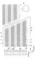
次に本発明の液体吐出ヘッドを構成するヘッド本体13について説明する。図2は、図1に示されたヘッド本体13を示す平面図である。図3は、図2の一点鎖線で囲まれた領域の拡大平面図であり、一部の流路を省略して描いている。図4は、図3と同じ位置の拡大透視図で、吐出孔8の位置が分かり易いように、図3とは異なる一部の流路を省略して描いている。なお、図3および図4において、図面を分かり易くするために、圧電アクチュエータ基板21の下方にあって破線で描くべき加圧室10(加圧室群9)、しぼり12および吐出孔8などを実線で描いている。図5(a)は図3のV−V線に沿った縦断面図であり、図5(b)は、図5(a)の要部の拡大図であり、図5(c)は、図5(a)の平面図である。   Next, the head main body 13 constituting the liquid discharge head of the present invention will be described. FIG. 2 is a plan view showing the head main body 13 shown in FIG. FIG. 3 is an enlarged plan view of a region surrounded by the alternate long and short dash line in FIG. 2, and a part of the flow paths are omitted. FIG. 4 is an enlarged perspective view of the same position as in FIG. 3, in which some flow paths different from those in FIG. 3 are omitted so that the positions of the discharge holes 8 can be easily understood. 3 and 4, in order to make the drawings easy to understand, the pressurizing chamber 10 (pressurizing chamber group 9), the squeezing chamber 12, the discharge hole 8, and the like that are to be drawn by broken lines below the piezoelectric actuator substrate 21 are illustrated. It is drawn with a solid line. 5A is a longitudinal sectional view taken along the line VV in FIG. 3, FIG. 5B is an enlarged view of the main part of FIG. 5A, and FIG. FIG. 6 is a plan view of FIG.

ヘッド本体13は、平板状の流路部材4と、流路部材4上に、圧電アクチュエータ基板21とを有している。圧電アクチュエータ基板21は台形形状を有しており、その台形の1対の平行対向辺が流路部材4の長手方向に平行になるように流路部材4の上面に配置されている。また、流路部材4の長手方向に平行な2本の仮想直線のそれぞれに沿って2つずつ、つまり合計4つの圧電アクチュエータ基板21が、全体として千鳥状に流路部材4上に配列されている。流路部材4上で隣接し合う圧電アクチュエータ基板21の斜辺同士は、流路部材4の短手方向について部分的にオーバーラップしている。このオーバーラップしている部分の圧電アクチェータ基板21を駆動することにより印刷される領域では、2つの圧電アクチュエータ基板21により吐出された液滴が混在して着弾することになる。   The head main body 13 has a flat plate-like channel member 4 and a piezoelectric actuator substrate 21 on the channel member 4. The piezoelectric actuator substrate 21 has a trapezoidal shape, and is disposed on the upper surface of the flow path member 4 so that a pair of parallel opposing sides of the trapezoid is parallel to the longitudinal direction of the flow path member 4. In addition, two piezoelectric actuator substrates 21 are arranged on the flow path member 4 as a whole in a zigzag manner, two along each of the two virtual straight lines parallel to the longitudinal direction of the flow path member 4. Yes. The oblique sides of the piezoelectric actuator substrates 21 adjacent to each other on the flow path member 4 partially overlap in the short direction of the flow path member 4. In the area printed by driving the overlapping piezoelectric actuator substrate 21, the droplets ejected by the two piezoelectric actuator substrates 21 are mixed and landed.

流路部材4の内部には液体流路の一部であるマニホールド5が形成されている。マニホールド5は流路部材4の長手方向に沿って延び細長い形状を有しており、流路部材4の上面にはマニホールド5の開口5bが形成されている。開口5bは、流路部材4の長手方向に平行な2本の直線(仮想線)のそれぞれに沿って5個ずつ、合計10個形成されている
。開口5bは、4つの圧電アクチュエータ基板21が配置された領域を避ける位置に形成されている。マニホールド5には開口5bを通じて図示されていない液体タンクから液体が供給されるようになっている。
A manifold 5 that is a part of the liquid flow path is formed inside the flow path member 4. The manifold 5 has an elongated shape extending along the longitudinal direction of the flow path member 4, and an opening 5 b of the manifold 5 is formed on the upper surface of the flow path member 4. A total of ten openings 5 b are formed along each of two straight lines (imaginary lines) parallel to the longitudinal direction of the flow path member 4. The opening 5b is formed at a position that avoids a region where the four piezoelectric actuator substrates 21 are disposed. The manifold 5 is supplied with liquid from a liquid tank (not shown) through the opening 5b.

流路部材4内に形成されたマニホールド5は、複数本に分岐している(分岐した部分のマニホールド5を副マニホールド5aということがある)。開口5bに繋がるマニホールド5は、圧電アクチュエータ基板21の斜辺に沿うように延在しており、流路部材4の長手方向と交差して配置されている。2つの圧電アクチュエータ基板21に挟まれた領域では、1つのマニホールド5が、隣接する圧電アクチュエータ基板21に共有されており、副マニホールド5aがマニホールド5の両側から分岐している。これらの副マニホールド5aは、流路部材4の内部の各圧電アクチュエータ基板21に対向する領域に互いに隣接してヘッド本体13の長手方向に延在している。   The manifold 5 formed in the flow path member 4 is branched into a plurality of branches (the manifold 5 at the branched portion may be referred to as a sub-manifold 5a). The manifold 5 connected to the opening 5 b extends along the oblique side of the piezoelectric actuator substrate 21 and is disposed so as to intersect with the longitudinal direction of the flow path member 4. In the region sandwiched between the two piezoelectric actuator substrates 21, one manifold 5 is shared by the adjacent piezoelectric actuator substrates 21, and the sub-manifold 5 a is branched from both sides of the manifold 5. These sub-manifolds 5 a extend in the longitudinal direction of the head main body 13 adjacent to each other in regions facing the piezoelectric actuator substrates 21 inside the flow path member 4.

流路部材4は、複数の加圧室10がマトリクス状(すなわち、2次元的かつ規則的)に形成されている4つの加圧室群9を有している。加圧室10は、角部にアールが施されたほぼ菱形の平面形状を有する中空の領域である。加圧室10は流路部材4の上面に開口するように形成されている。これらの加圧室10は、流路部材4の上面における圧電アクチュエータ基板21に対向する領域のほぼ全面にわたって配列されている。したがって、これらの加圧室10によって形成された各加圧室群9は圧電アクチュエータ基板21とほぼ同一の形状の領域を占有している。また、圧電アクチュエータ基板21は複数の加圧室10を覆うように積層されるので、各加圧室10の開口は、圧電アクチュエータ基板21で閉塞されている。   The flow path member 4 has four pressure chamber groups 9 in which a plurality of pressure chambers 10 are formed in a matrix (that is, two-dimensionally and regularly). The pressurizing chamber 10 is a hollow region having a substantially rhombic planar shape with rounded corners. The pressurizing chamber 10 is formed so as to open on the upper surface of the flow path member 4. These pressurizing chambers 10 are arranged over almost the entire surface of the upper surface of the flow path member 4 facing the piezoelectric actuator substrate 21. Accordingly, each pressurizing chamber group 9 formed by these pressurizing chambers 10 occupies a region having substantially the same shape as the piezoelectric actuator substrate 21. Further, since the piezoelectric actuator substrate 21 is laminated so as to cover the plurality of pressurizing chambers 10, the opening of each pressurizing chamber 10 is closed by the piezoelectric actuator substrate 21.

本実施形態では、図3に示されているように、マニホールド5は、流路部材4の短手方向に互いに平行に並んだ4列のE1〜E4の副マニホールド5aに分岐し、各副マニホールド5aに繋がった加圧室10は、等間隔に流路部材4の長手方向に並ぶ加圧室10の列を構成し、その列は、短手方向に互いに平行に4列配列されている。副マニホールド5aに繋がった加圧室10の並ぶ列は副マニホールド5aの両側に2列ずつ配列されている。   In the present embodiment, as shown in FIG. 3, the manifold 5 branches into four rows of E1-E4 sub-manifolds 5a arranged in parallel with each other in the short direction of the flow path member 4, and each sub-manifold The pressurizing chambers 10 connected to 5a constitute a row of the pressurizing chambers 10 arranged in the longitudinal direction of the flow path member 4 at equal intervals, and the four rows are arranged in parallel to each other in the lateral direction. Two rows of the pressure chambers 10 connected to the sub-manifold 5a are arranged on both sides of the sub-manifold 5a.

全体では、マニホールド5から繋がる加圧室10は、等間隔に流路部材4の長手方向に並ぶ加圧室10の列を構成し、その列は、短手方向に互いに平行に16列配列されている。各加圧室列に含まれる加圧室10の数は、アクチュエータである変位素子50の外形形状に対応して、その長辺側から短辺側に向かって次第に少なくなるように配置されている。吐出孔8もこれと同様に配置されている。これによって、全体として長手方向に600dpiの解像度で画像形成が可能となっている。   As a whole, the pressurizing chambers 10 connected from the manifold 5 constitute rows of the pressurizing chambers 10 arranged in the longitudinal direction of the flow path member 4 at equal intervals, and the rows are arranged in 16 rows parallel to each other in the short side direction. ing. The number of pressurizing chambers 10 included in each pressurizing chamber row is arranged so as to gradually decrease from the long side toward the short side corresponding to the outer shape of the displacement element 50 that is an actuator. . The discharge holes 8 are also arranged in the same manner. As a result, it is possible to form an image with a resolution of 600 dpi in the longitudinal direction as a whole.

つまり、流路部材4の長手方向に平行な仮想直線に対して直交するように吐出孔8を投影すると、図3に示した仮想直線のRの範囲に、4つの副マニホールド5aに繋がっている4つの吐出孔8、つまり全部で16個の吐出孔8が600dpiの等間隔に配置されている。また、各副マニホールド5aには平均すれば150dpiに相当する間隔で個別流路32が接続されている。これは、600dpi分の吐出孔8を4つ列の副マニホールド5aに分けて繋ぐ設計をする際に、各副マニホールド5aに繋がる個別流路32が等しい間隔で繋がるとは限らないため、マニホールド5aの延在方向、すなわち主走査方向に平均170μm(150dpiならば25.4mm/150=169μm間隔である)以下の間隔で個別流路32が形成されているということである。   That is, when the discharge hole 8 is projected so as to be orthogonal to a virtual straight line parallel to the longitudinal direction of the flow path member 4, it is connected to the four sub-manifolds 5a in the range of R of the virtual straight line shown in FIG. Four discharge holes 8, that is, a total of 16 discharge holes 8 are arranged at equal intervals of 600 dpi. Moreover, the individual flow paths 32 are connected to the sub manifolds 5a at intervals corresponding to 150 dpi on average. This is because when the discharge holes 8 for 600 dpi are divided and connected to the four sub-manifolds 5a, the individual flow paths 32 connected to the sub-manifolds 5a are not always connected at equal intervals. In other words, the individual flow paths 32 are formed at intervals of an average of 170 μm (25.4 mm / 150 = 169 μm intervals if 150 dpi) in the main scanning direction.

圧電アクチュエータ基板21の上面における各加圧室10に重なる位置には個別電極35がそれぞれ形成されている。すなわち、個別電極35は、圧電アクチュエータ基板21の上面に、第1の方向および第1の方向とは異なる方向にわたって形成されている。個別電極35は、個別電極本体35aと個別電極35aから引き出された引出電極35bとを
含む。個別電極本体35aは、加圧室10より一回り小さく、加圧室10とほぼ相似な形状を有しており、圧電アクチュエータ基板21の上面における加圧室10と対向する領域内に収まるように配置されている。
Individual electrodes 35 are formed on the upper surface of the piezoelectric actuator substrate 21 at positions overlapping the pressurizing chambers 10 respectively. That is, the individual electrode 35 is formed on the upper surface of the piezoelectric actuator substrate 21 in a direction different from the first direction and the first direction. The individual electrode 35 includes an individual electrode body 35a and an extraction electrode 35b that is extracted from the individual electrode 35a. The individual electrode main body 35 a is slightly smaller than the pressurizing chamber 10 and has a shape substantially similar to the pressurizing chamber 10, so that the individual electrode main body 35 a fits in a region facing the pressurizing chamber 10 on the upper surface of the piezoelectric actuator substrate 21. Has been placed.

流路部材4の下面には多数の吐出孔8が形成されている。これらの吐出孔8は、流路部材4の下面側に配置された副マニホールド5aと対向する領域を避けた位置に配置されている。また、これらの吐出孔8は、流路部材4の下面側における圧電アクチュエータ基板21と対向する領域内に配置されている。これらの吐出孔群7は圧電アクチュエータ基板21とほぼ同一の形状の領域を占有しており、対応する圧電アクチュエータ基板21の変位素子50を変位させることにより吐出孔8から液滴が吐出できる。吐出孔8の配置については後で詳述する。そして、それぞれの領域内の吐出孔8は、流路部材4の長手方向に平行な複数の直線に沿って等間隔に配列されている。   A large number of discharge holes 8 are formed in the lower surface of the flow path member 4. These discharge holes 8 are arranged at positions avoiding the area facing the sub-manifold 5a arranged on the lower surface side of the flow path member 4. Further, these discharge holes 8 are arranged in a region facing the piezoelectric actuator substrate 21 on the lower surface side of the flow path member 4. These discharge hole groups 7 occupy regions having substantially the same shape as the piezoelectric actuator substrate 21, and droplets can be discharged from the discharge holes 8 by displacing the corresponding displacement elements 50 of the piezoelectric actuator substrate 21. The arrangement of the discharge holes 8 will be described in detail later. The discharge holes 8 in each region are arranged at equal intervals along a plurality of straight lines parallel to the longitudinal direction of the flow path member 4.

ヘッド本体13に含まれる流路部材4は、複数のプレートが積層された積層構造を有している。これらのプレートは、流路部材4の上面から順に、キャビティプレート22、ベースプレート23、アパーチャ(しぼり)プレート24、サプライプレート25、26、マニホールドプレート27、28、29、カバープレート30およびノズルプレート31である。これらのプレートには多数の孔が形成されている。各プレートは、これらの孔が互いに連通して個別流路32および副マニホールド5aを構成するように、位置合わせして積層されている。ヘッド本体13は、図5に示されているように、加圧室10は流路部材4の上面に、副マニホールド5aは内部の下面側に、吐出孔8は下面にと、個別流路32を構成する各部分が異なる位置に互いに近接して配設され、加圧室10を介して副マニホールド5aと吐出孔8とが繋がる構成を有している。   The flow path member 4 included in the head body 13 has a stacked structure in which a plurality of plates are stacked. These plates are a cavity plate 22, a base plate 23, an aperture (squeezing) plate 24, supply plates 25 and 26, manifold plates 27, 28 and 29, a cover plate 30 and a nozzle plate 31 in order from the upper surface of the flow path member 4. is there. A number of holes are formed in these plates. Each plate is aligned and laminated so that these holes communicate with each other to form the individual flow path 32 and the sub-manifold 5a. As shown in FIG. 5, the head body 13 has the pressurizing chamber 10 on the upper surface of the flow path member 4, the sub-manifold 5 a on the inner lower surface side, and the discharge holes 8 on the lower surface. Are arranged close to each other at different positions, and the sub-manifold 5 a and the discharge hole 8 are connected via the pressurizing chamber 10.

各プレートに形成された孔について説明する。これらの孔には、次のようなものがある。第1に、キャビティプレート22に形成された加圧室10である。第2に、加圧室10の一端から副マニホールド5aへと繋がる流路を構成する連通孔である。この連通孔は、ベースプレート23(詳細には加圧室10の入り口)からサプライプレート25(詳細には副マニホールド5aの出口)までの各プレートに形成されている。なお、この連通孔には、アパーチャプレート24に形成されたしぼり12と、サプライプレート25、26に形成された個別供給流路6とが含まれている。   The holes formed in each plate will be described. These holes include the following. First, the pressurizing chamber 10 formed in the cavity plate 22. Secondly, there is a communication hole that constitutes a flow path that connects from one end of the pressurizing chamber 10 to the sub-manifold 5a. This communication hole is formed in each plate from the base plate 23 (specifically, the inlet of the pressurizing chamber 10) to the supply plate 25 (specifically, the outlet of the sub-manifold 5a). The communication hole includes the aperture 12 formed in the aperture plate 24 and the individual supply flow path 6 formed in the supply plates 25 and 26.

第3に、加圧室10の他端から吐出孔8へと連通する流路を構成する連通孔であり、この連通孔は、以下の記載においてディセンダ(部分流路)と呼称される。ディセンダは、ベースプレート23(詳細には加圧室10の出口)からノズルプレート31(詳細には吐出孔8)までの各プレートに形成されている。第4に、副マニホールド5aを構成する連通孔である。この連通孔は、マニホールドプレート27〜29に形成されている。   Third, there is a communication hole constituting a flow path communicating from the other end of the pressurizing chamber 10 to the discharge hole 8, and this communication hole is referred to as a descender (partial flow path) in the following description. The descender is formed on each plate from the base plate 23 (specifically, the outlet of the pressurizing chamber 10) to the nozzle plate 31 (specifically, the discharge hole 8). Fourthly, there is a communication hole constituting the sub-manifold 5a. The communication holes are formed in the manifold plates 27 to 29.

このような連通孔が相互に繋がり、副マニホールド5aからの液体の流入口(副マニホールド5aの出口)から吐出孔8に至る個別流路32を構成している。副マニホールド5aに供給された液体は、以下の経路で吐出孔8から吐出される。まず、副マニホールド5aから上方向に向かって、個別供給流路6を通り、しぼり12の一端部に至る。次に、しぼり12の延在方向に沿って水平に進み、しぼり12の他端部に至る。そこから上方に向かって、加圧室10の一端部に至る。さらに、加圧室10の延在方向に沿って水平に進み、加圧室10の他端部に至る。そこから少しずつ水平方向に移動しながら、主に下方に向かい、下面に開口した吐出孔8へと進む。   Such communication holes are connected to each other to form an individual flow path 32 extending from the liquid inflow port (the outlet of the submanifold 5a) from the submanifold 5a to the discharge hole 8. The liquid supplied to the sub-manifold 5a is discharged from the discharge hole 8 through the following path. First, from the sub-manifold 5a, it passes through the individual supply flow path 6 and reaches one end of the aperture 12. Next, it proceeds horizontally along the extending direction of the aperture 12 and reaches the other end of the aperture 12. From there, it reaches one end of the pressurizing chamber 10 upward. Furthermore, it progresses horizontally along the extending direction of the pressurizing chamber 10 and reaches the other end of the pressurizing chamber 10. While moving little by little in the horizontal direction from there, it proceeds mainly downward and proceeds to the discharge hole 8 opened in the lower surface.

また、プレート22には、上述したような、吐出される液体が流れる流路以外に、空隙部38が形成されている。空隙部38は、プレート22の上側が窪んで形成されているが、プレート22を貫通する孔として形成してもよい。空隙部38ついては、後で詳述する
In addition to the flow path through which the liquid to be discharged flows as described above, a gap 38 is formed in the plate 22. The gap portion 38 is formed so as to be depressed on the upper side of the plate 22, but may be formed as a hole penetrating the plate 22. The gap 38 will be described in detail later.

圧電アクチュエータ基板21は、図5に示されるように、2枚の圧電セラミック層21a、21bからなる積層構造を有している。これらの圧電セラミック層21a、21bはそれぞれ20μm程度の厚さを有している。圧電アクチュエータ基板21の圧電セラミック層21a、21bの積層体の厚さは40μm程度であり、100μm以下であることにより、変位量を大きくすることができる。圧電アクチュエータ基板21は、流路部材4の加圧室10の開口している平面状の面に積層されており、圧電セラミック層21a、21bのいずれの層も複数の加圧室10を跨ぐように延在している(図3参照)。これらの圧電セラミック層21a、21bは、強誘電性を有するチタン酸ジルコン酸鉛(PZT)系のセラミックス材料からなる。   As shown in FIG. 5, the piezoelectric actuator substrate 21 has a laminated structure including two piezoelectric ceramic layers 21a and 21b. Each of these piezoelectric ceramic layers 21a and 21b has a thickness of about 20 μm. The thickness of the laminated body of the piezoelectric ceramic layers 21a and 21b of the piezoelectric actuator substrate 21 is about 40 μm, and the displacement can be increased by being 100 μm or less. The piezoelectric actuator substrate 21 is laminated on the planar surface of the flow path member 4 where the pressurizing chamber 10 is open, and the piezoelectric ceramic layers 21 a and 21 b straddle the plurality of pressurizing chambers 10. (See FIG. 3). The piezoelectric ceramic layers 21a and 21b are made of a lead zirconate titanate (PZT) ceramic material having ferroelectricity.

圧電アクチュエータ基板21は、Ag−Pd系などの金属材料からなる共通電極34、Au系などの金属材料からなる個別電極35を有している。必要に応じて、個別電極35の上に形成されているAg系などの金属材料からなる接続電極36を形成してもよい。個別電極35は、圧電アクチュエータ基板21の上面における加圧室10と重なる位置に配置されている個別電極本体35aと、個別電極本体35aから加圧室10と重ならない位置まで引き出されている引出電極35bとを含んでいる。引出電極35bの加圧室10のない位置には、接続電極36が形成されている。個別電極35の厚さは、0.3〜1μmである。接続電極36は例えばガラスフリットを含む銀からなり、厚さが1〜15μm程度で凸状に形成されている。また、接続電極36は、図示されていないFPC(Flexible
Printed Circuit)に設けられた電極と電気的に接合されている。詳細は後述するが、個別電極35には、制御部100からFPCを通じて駆動信号(駆動電圧)が供給される。駆動信号は、印刷媒体Pの搬送速度と同期して一定の周期で供給される。
The piezoelectric actuator substrate 21 has a common electrode 34 made of a metal material such as Ag—Pd and an individual electrode 35 made of a metal material such as Au. If necessary, a connection electrode 36 made of an Ag-based metal material formed on the individual electrode 35 may be formed. The individual electrode 35 is disposed at a position overlapping the pressurizing chamber 10 on the upper surface of the piezoelectric actuator substrate 21, and the extraction electrode is drawn from the individual electrode main body 35 a to a position not overlapping the pressurizing chamber 10. 35b. A connection electrode 36 is formed at a position of the extraction electrode 35b where the pressurizing chamber 10 is not provided. The thickness of the individual electrode 35 is 0.3 to 1 μm. The connection electrode 36 is made of, for example, silver containing glass frit, and has a thickness of about 1 to 15 μm and is formed in a convex shape. Further, the connection electrode 36 is not shown in FPC (Flexible).
It is electrically joined to the electrode provided in the printed circuit. Although details will be described later, a drive signal (drive voltage) is supplied to the individual electrode 35 from the control unit 100 through the FPC. The drive signal is supplied in a constant cycle in synchronization with the conveyance speed of the print medium P.

共通電極34は、圧電セラミック層(セラミック振動板)21aと圧電セラミック層(圧電体層)21bとの間の領域に面方向のほぼ全面にわたって形成されている。すなわち、共通電極34は、圧電アクチュエータ基板21に対向する領域内の全ての加圧室10を覆うように延在している。共通電極34の厚さは2μm程度である。共通電極34は図示しない領域において接地され、グランド電位に保持されている。本実施形態では、圧電セラミック層21b上において、個別電極35からなる電極群を避ける位置に個別電極35とは異なる表面電極(不図示)が形成されている。表面電極は、圧電セラミック層21bの内部に形成されたスルーホールを介して共通電極34と電気的に接続されているとともに、多数の個別電極35と同様に、外部配線内の別の電極と接続されている。   The common electrode 34 is formed over almost the entire surface in the region between the piezoelectric ceramic layer (ceramic diaphragm) 21a and the piezoelectric ceramic layer (piezoelectric layer) 21b. That is, the common electrode 34 extends so as to cover all the pressurizing chambers 10 in the region facing the piezoelectric actuator substrate 21. The thickness of the common electrode 34 is about 2 μm. The common electrode 34 is grounded in a region not shown, and is held at the ground potential. In the present embodiment, a surface electrode (not shown) different from the individual electrode 35 is formed on the piezoelectric ceramic layer 21b at a position avoiding the electrode group composed of the individual electrodes 35. The surface electrode is electrically connected to the common electrode 34 through a through-hole formed in the piezoelectric ceramic layer 21b, and is connected to another electrode in the external wiring, like the large number of individual electrodes 35. Has been.

図5(a)に示されるように、共通電極34と個別電極35とは、最上層の圧電セラミック層21bのみを挟むように配置されている。圧電セラミック層21bにおける個別電極35と共通電極34とに挟まれた領域は活性部と呼称され、その部分の圧電セラミックスには厚み方向に分極が施されている。本実施形態の圧電アクチュエータ基板21においては、最上層の圧電セラミック層21bのみが活性部を含んでおり、圧電セラミック21aは活性部を含んでおらず、振動板として働く。この圧電アクチュエータ基板21はいわゆるユニモルフタイプの構成を有している。   As shown in FIG. 5A, the common electrode 34 and the individual electrode 35 are disposed so as to sandwich only the uppermost piezoelectric ceramic layer 21b. A region sandwiched between the individual electrode 35 and the common electrode 34 in the piezoelectric ceramic layer 21b is called an active portion, and the piezoelectric ceramic in that portion is polarized in the thickness direction. In the piezoelectric actuator substrate 21 of the present embodiment, only the uppermost piezoelectric ceramic layer 21b includes an active portion, and the piezoelectric ceramic 21a does not include an active portion and functions as a diaphragm. The piezoelectric actuator substrate 21 has a so-called unimorph type configuration.

なお、後述のように、個別電極35に選択的に所定の駆動信号が供給されることにより、この個別電極35に対応する加圧室10内の液体に圧力が加えられる。これによって、個別流路32を通じて、対応する液体吐出口8から液滴が吐出される。すなわち、圧電アクチュエータ基板21における各加圧室10に対向する部分は、各加圧室10および液体吐出口8に対応する個別の変位素子50に相当する。つまり、2枚の圧電セラミック層からなる積層体中には、図5に示されているような構造を単位構造とする変位素子50が加圧室10毎に、加圧室10の直上に位置するセラミック振動板21a、共通電極34、圧
電セラミック層21b、個別電極35により作り込まれており、圧電アクチュエータ基板21には変位素子50が複数含まれている。なお、本実施形態において1回の吐出動作によって液体吐出口8から吐出される液体の量は5〜7pL(ピコリットル)程度である。
As will be described later, when a predetermined drive signal is selectively supplied to the individual electrode 35, pressure is applied to the liquid in the pressurizing chamber 10 corresponding to the individual electrode 35. As a result, droplets are discharged from the corresponding liquid discharge ports 8 through the individual flow paths 32. That is, the portion of the piezoelectric actuator substrate 21 that faces each pressurizing chamber 10 corresponds to the individual displacement element 50 corresponding to each pressurizing chamber 10 and the liquid discharge port 8. That is, in the laminate composed of two piezoelectric ceramic layers, the displacement element 50 having a unit structure as shown in FIG. 5 is positioned immediately above the pressurizing chamber 10 for each pressurizing chamber 10. The ceramic diaphragm 21a, the common electrode 34, the piezoelectric ceramic layer 21b, and the individual electrode 35 are formed, and the piezoelectric actuator substrate 21 includes a plurality of displacement elements 50. In the present embodiment, the amount of liquid ejected from the liquid ejection port 8 by one ejection operation is about 5 to 7 pL (picoliter).

本実施形態における圧電アクチュエータ基板21の液体吐出時の駆動方法の一例を、個別電極35に供給される駆動電圧(駆動信号)に関して説明する。個別電極35を共通電極34と異なる電位にして圧電セラミック層21bに対してその分極方向に電界を印加したとき、この電界が印加された部分が、圧電効果により歪む活性部として働く。この時圧電セラミック層21bは、その厚み方向すなわち積層方向に伸長または収縮し、圧電横効果により積層方向と垂直な方向、すなわち面方向には収縮または伸長しようとする。一方、残りの圧電セラミック層21aは、個別電極35と共通電極34とに挟まれた領域を持たない非活性層であるので、自発的に変形しない。つまり、圧電アクチュエータ基板21は、上側(つまり、加圧室10とは離れた側)の圧電セラミック層21bを、活性部を含む層とし、かつ下側(つまり、加圧室10に近い側)の圧電セラミック層21aを非活性層とした、いわゆるユニモルフタイプの構成となっている。   An example of a driving method at the time of liquid ejection of the piezoelectric actuator substrate 21 in the present embodiment will be described with respect to a driving voltage (drive signal) supplied to the individual electrode 35. When an electric field is applied to the piezoelectric ceramic layer 21b in the polarization direction by setting the individual electrode 35 to a potential different from that of the common electrode 34, the portion to which the electric field is applied functions as an active portion that is distorted by the piezoelectric effect. At this time, the piezoelectric ceramic layer 21b expands or contracts in the thickness direction, that is, the stacking direction, and tends to contract or extend in the direction perpendicular to the stacking direction, that is, the plane direction, due to the piezoelectric lateral effect. On the other hand, since the remaining piezoelectric ceramic layer 21a is an inactive layer that does not have a region sandwiched between the individual electrode 35 and the common electrode 34, it does not spontaneously deform. That is, the piezoelectric actuator substrate 21 has the piezoelectric ceramic layer 21b on the upper side (that is, the side away from the pressurizing chamber 10) as a layer including the active portion and the lower side (that is, the side close to the pressurizing chamber 10). This piezoceramic layer 21a is a so-called unimorph type structure having an inactive layer.

この構成において、電界と分極とが同方向となるように、アクチュエータ制御部により個別電極35を共通電極34に対して正または負の所定電位とすると、圧電セラミック層21bの電極に挟まれた部分(活性部)が、面方向に収縮する。一方、非活性層の圧電セラミック層21aは電界の影響を受けないため、自発的には縮むことがなく活性部の変形を規制しようとする。この結果、圧電セラミック層21bと圧電セラミック層21aとの間で分極方向への歪みに差が生じて、圧電セラミック層21bは加圧室10側へ凸となるように変形(ユニモルフ変形)する。   In this configuration, when the individual electrode 35 is set to a predetermined positive or negative potential with respect to the common electrode 34 by the actuator controller so that the electric field and the polarization are in the same direction, a portion sandwiched between the electrodes of the piezoelectric ceramic layer 21b. (Active part) contracts in the surface direction. On the other hand, the piezoelectric ceramic layer 21a, which is an inactive layer, is not affected by an electric field, so that it does not spontaneously shrink and tries to restrict deformation of the active portion. As a result, there is a difference in strain in the polarization direction between the piezoelectric ceramic layer 21b and the piezoelectric ceramic layer 21a, and the piezoelectric ceramic layer 21b is deformed so as to protrude toward the pressurizing chamber 10 (unimorph deformation).

本実施の形態における実際の駆動手順は、あらかじめ個別電極35を共通電極34より高い電位(以下高電位と称す)にしておき、吐出要求がある毎に個別電極35を共通電極34と一旦同じ電位(以下低電位と称す)とし、その後所定のタイミングで再び高電位とする。これにより、個別電極35が低電位になるタイミングで、圧電セラミック層21a、bが元の形状に戻り、加圧室10の容積が初期状態(両電極の電位が異なる状態)と比較して増加する。このとき、加圧室10内に負圧が与えられ、液体がマニホールド5側から加圧室10内に吸い込まれる。その後再び個別電極35を高電位にしたタイミングで、圧電セラミック層21a、bが加圧室10側へ凸となるように変形し、加圧室10の容積減少により加圧室10内の圧力が正圧となり液体への圧力が上昇し、液滴が吐出される。つまり、液滴を吐出させるため、高電位を基準とするパルスを含む駆動信号を個別電極35に供給することになる。このパルス幅は、圧力波がしぼり12から吐出孔8まで伝播する時間長さであるAL(Acoustic Length)が理想的である。これによると、加圧室10
内部が負圧状態から正圧状態に反転するときに両者の圧力が合わさり、より強い圧力で液滴を吐出させることができる。
In an actual driving procedure in the present embodiment, the individual electrode 35 is set to a potential higher than the common electrode 34 (hereinafter referred to as a high potential) in advance, and the individual electrode 35 is temporarily set to the same potential as the common electrode 34 every time there is a discharge request. (Hereinafter referred to as a low potential), and then set to a high potential again at a predetermined timing. As a result, the piezoelectric ceramic layers 21a and 21b return to their original shapes at the timing when the individual electrodes 35 become low potential, and the volume of the pressurizing chamber 10 increases compared to the initial state (the state where the potentials of both electrodes are different). To do. At this time, a negative pressure is applied to the pressurizing chamber 10 and the liquid is sucked into the pressurizing chamber 10 from the manifold 5 side. Thereafter, at the timing when the individual electrode 35 is set to a high potential again, the piezoelectric ceramic layers 21a and 21b are deformed so as to protrude toward the pressurizing chamber 10, and the pressure in the pressurizing chamber 10 is reduced due to the volume reduction of the pressurizing chamber 10. The pressure becomes positive and the pressure on the liquid rises, and droplets are ejected. That is, a drive signal including a pulse based on a high potential is supplied to the individual electrode 35 in order to eject a droplet. The ideal pulse width is AL (Acoustic Length), which is the length of time that the pressure wave propagates from the orifice 12 to the discharge hole 8. According to this, the pressure chamber 10
When the inside is reversed from the negative pressure state to the positive pressure state, both pressures are combined, and the liquid droplets can be ejected at a stronger pressure.

以上のような液体吐出ヘッド2において、外部から信号を供給する電極により変位素子50の変位を阻害しないように、引出電極35bは、加圧室10の外にまで引き出されている。しかし、そうすることにより、引出電極35bと共通電極34との間に挟まれている、引出電極35bの直下の圧電セラミック層21b(以下で、この部位を引出部駆動部ということがある)も圧電駆動されることになる。この圧電駆動による、振動あるいは応力が、周囲の液体吐出素子に伝わると、その動作に影響を与えるためクロストークが生じ、印刷精度を低下させる。この現象は、引出部駆動部が分極されている液体吐出ヘッド2で顕著であり、本発明は、そのような液体吐出ヘッド2において、特に効果がある。   In the liquid ejection head 2 as described above, the extraction electrode 35 b is extracted to the outside of the pressurizing chamber 10 so as not to inhibit the displacement of the displacement element 50 by an electrode that supplies a signal from the outside. However, by doing so, there is also a piezoelectric ceramic layer 21b directly below the extraction electrode 35b sandwiched between the extraction electrode 35b and the common electrode 34 (hereinafter, this portion may be referred to as an extraction portion drive unit). Piezoelectrically driven. When vibration or stress due to this piezoelectric drive is transmitted to the surrounding liquid ejection elements, the operation is affected, so that crosstalk occurs and printing accuracy is lowered. This phenomenon is conspicuous in the liquid discharge head 2 in which the drawer drive unit is polarized, and the present invention is particularly effective in such a liquid discharge head 2.

この影響を低減させるために、流路部材4に空隙部38を設ける。空隙部38は、引出電極35bの直下にあり、引出部駆動部が圧電駆動された際に、変形する余地を与える。
これにより、周囲に与える応力を低減させ、クロストークを低減させる。クロストークは、圧電セラミック層21bが隣り合う変位素子50の間で繋がっている場合、応力が直接的に伝わるのでその影響が大きくなるので、空隙部38を設けることによる応力の低減は、そのような液体吐出ヘッド2において特に効果がある。
In order to reduce this influence, the gap member 38 is provided in the flow path member 4. The gap portion 38 is directly below the extraction electrode 35b, and provides a room for deformation when the extraction portion driving portion is piezoelectrically driven.
Thereby, the stress given to the surroundings is reduced and crosstalk is reduced. The crosstalk is affected when the piezoelectric ceramic layer 21b is connected between the adjacent displacement elements 50, so that the stress is directly transmitted. Therefore, the influence of the crosstalk is increased. This is particularly effective in a liquid discharge head 2 that is easy to use.

ここで言う直下とは、真下の意味であり、空隙部38は、引出電極35bから、圧電アクチュエータ基板21と流路部材4との境界面に対して直交する方向のうちで、流路部材4に向かう方向に位置している。言い換えれば、ヘッド本体13を平面視すると、引出電極35bと空隙部38とは、少なくとも一部が重なっている。重なりは、大きい方が、応力緩和の効果が大きくなるので好ましい。   Here, the term “directly below” means directly below, and the gap 38 is formed in the direction perpendicular to the boundary surface between the piezoelectric actuator substrate 21 and the flow path member 4 from the extraction electrode 35b. Located in the direction toward. In other words, when the head body 13 is viewed in plan, at least a part of the extraction electrode 35b and the gap portion 38 overlap each other. A larger overlap is preferable because the stress relaxation effect is increased.

しかし、引出電極35bは、外部との電気的接続の際などに外部から力が加わる部分であり、外部からの力で圧電セラミック層21bなどが破損してしまうおそれがある。そのため空隙部38の大きさ(幅など)は、引出電極の50〜150%とするのが好ましく、特に80〜120%とするのがよい。   However, the extraction electrode 35b is a portion to which a force is applied from the outside when electrically connecting to the outside, and the piezoelectric ceramic layer 21b and the like may be damaged by the force from the outside. Therefore, the size (width, etc.) of the gap 38 is preferably 50 to 150% of the extraction electrode, particularly 80 to 120%.

空隙部38は、吐出孔8とは繋がっておらず、吐出される液体は入ってこないようにされる。吐出される液体が入ってくると、空隙部38が変形し難くなるので、応力緩和の効果が低下する上、引出部駆動部の振動が空隙部38中の液体を通じて他の流路に伝わるので、クロストークが生じるおそれもある。   The gap portion 38 is not connected to the discharge hole 8 so that the discharged liquid does not enter. When the liquid to be ejected enters, the gap portion 38 becomes difficult to be deformed, so that the effect of stress relaxation is reduced, and the vibration of the drawer drive portion is transmitted to other flow paths through the liquid in the gap portion 38. There is also a risk of crosstalk.

空隙部38をヘッド本体13の外部の空間と繋げて、空気などが出入り可能にしてもよいが、空隙部38の変形量は小さいので、そのようにする必要性は高くない。また、上述のように、圧電アクチュエータ基板21が破損し難いように、空隙部38は、引出電極35bの直下(およびその近傍)を離れて流路部材4の平面方向へ広がっていないのが好ましい。空隙部38を外部と繋げる際には、一旦、流路部材4の下側(吐出孔面4−1側)に向かって広がり、その先で外部に繋がるようにするのが好ましい。   The gap 38 may be connected to a space outside the head body 13 so that air and the like can enter and exit. However, since the amount of deformation of the gap 38 is small, the necessity for doing so is not high. Further, as described above, it is preferable that the gap portion 38 does not extend in the planar direction of the flow path member 4 away from (below) the extraction electrode 35b so that the piezoelectric actuator substrate 21 is not easily damaged. . When connecting the gap 38 to the outside, it is preferable that the gap 38 once extends toward the lower side (discharge hole surface 4-1 side) of the flow path member 4 and is connected to the outside at the end.

引出部駆動部の直下に、吐出される液体が流れる流路が存在すると、その流路内の液体に振動を与えて、クロストークが生じるおそれがある。そのため、引出部駆動部の直下には、流路を設けないのが好ましい。しかし、印刷精度を高くするためには、ヘッド本体13の大きさを小さくする必要があるので、流路を高密度に配置しなければならず、現実的には、そのように設計するのは難しい。引出部駆動部の直下に流路を配置する場合には、その流路より圧電アクチュエータ基板21に近い位置に空隙部38を設けることで、クロストークの発生を抑制できる。   If there is a channel through which the liquid to be discharged flows directly under the drawer drive unit, vibration may be applied to the liquid in the channel and crosstalk may occur. Therefore, it is preferable not to provide a flow path directly under the drawer drive unit. However, since it is necessary to reduce the size of the head body 13 in order to increase the printing accuracy, the flow paths must be arranged at a high density. difficult. In the case where the flow path is arranged immediately below the lead-out section drive section, the occurrence of crosstalk can be suppressed by providing the gap portion 38 at a position closer to the piezoelectric actuator substrate 21 than the flow path.

引出電極35bの引出方向に直交する方向の幅をW[μm]としたとき、空隙部38(より正確には空隙部38の上端)を、圧電アクチュエータ基板21からW[μm]以下の距離に配置することで、応力緩和の効果を高くできる。Wは、例えば、30〜100μm程度である。応力緩和の効果を特に高くにするには、空隙部38は、圧電アクチュエータ基板21と流路部材4との境界に設けるのが好ましい。   When the width of the extraction electrode 35b in the direction orthogonal to the extraction direction is W [μm], the gap portion 38 (more precisely, the upper end of the gap portion 38) is set to a distance of W [μm] or less from the piezoelectric actuator substrate 21. By arranging, the effect of stress relaxation can be enhanced. W is, for example, about 30 to 100 μm. In order to make the stress relaxation effect particularly high, the gap 38 is preferably provided at the boundary between the piezoelectric actuator substrate 21 and the flow path member 4.

空隙部38は、図5(b)のように、プレート22の上側をハーフエッチングして、窪みとして形成してもよいし、プレート22を貫通する孔として形成してもよい。また、圧電アクチュエータ基板21と流路部材4とを接着剤層を介して積層している場合、その部分に接着剤が存在しないようにすることで空隙部38を形成してもよい。引出電極35b直下の圧電駆動は100nm程度であるので、例えば、500nm以上の接着剤層を形成すれば、接着剤の存在しない部位を設けることで、その部位が空隙部38として十分機能する。   As shown in FIG. 5B, the gap 38 may be formed as a recess by half-etching the upper side of the plate 22 or as a hole penetrating the plate 22. Further, when the piezoelectric actuator substrate 21 and the flow path member 4 are laminated via an adhesive layer, the gap portion 38 may be formed by preventing the adhesive from being present in that portion. Since the piezoelectric drive just below the extraction electrode 35b is about 100 nm, for example, if an adhesive layer having a thickness of 500 nm or more is formed, by providing a portion where no adhesive is present, that portion functions sufficiently as the gap 38.

流路部材4の内部に空隙部38の内部に配置する場合にも同様に、窪みや孔を形成したプレートを配置すればよい。各プレートが接着剤層を介して積層している場合には、接着剤の存在しない部位を空隙部38としてもよい。   Similarly, in the case of disposing inside the gap portion 38 inside the flow path member 4, a plate having depressions or holes may be disposed. When each plate is laminated via an adhesive layer, a portion where no adhesive is present may be used as the gap 38.

図6(a)は、本発明の他の液体吐出ヘッドの部分断面図であり、図6(b)は、図6(a)の部位の部分平面図である。この液体吐出ヘッドの基本構造は、図1〜5で示したものと同じであり、差異の少ない部分については、同じ符号を付けて説明を省略する。   FIG. 6A is a partial cross-sectional view of another liquid discharge head of the present invention, and FIG. 6B is a partial plan view of the portion of FIG. The basic structure of the liquid discharge head is the same as that shown in FIGS. 1 to 5, and parts with little difference are given the same reference numerals and description thereof is omitted.

流路部材204は、流路部材4のプレート22の上にプレート220が積層された構造となっている。加圧室10の上側は、プレート220で覆われて、塞がれている。図ではプレート22より下側のプレートは省略してある。   The flow path member 204 has a structure in which a plate 220 is laminated on the plate 22 of the flow path member 4. The upper side of the pressurizing chamber 10 is covered with a plate 220 and closed. In the figure, the plate below the plate 22 is omitted.

圧電アクチュエータ基板21と、流路部材204とは接着剤層240を介して積層されている。プレート220とプレート22とも接着剤を介して積層されているが、図では省略してある。引出電極35bの直下には、接着剤層240が存在しない部位があり、空隙部238となっている。接着剤層240は0.2〜2μm程度の厚さにされる。厚さが0.2μm以上あれば、引出部駆動部が圧電変形しても、空隙部238において、圧電アクチュエータ基板21とプレート220とが接触し難いの、応力緩和効果が低下し難い。   The piezoelectric actuator substrate 21 and the flow path member 204 are laminated via an adhesive layer 240. Both the plate 220 and the plate 22 are laminated via an adhesive, but are omitted in the figure. Immediately below the extraction electrode 35 b, there is a portion where the adhesive layer 240 does not exist, which is a gap 238. The adhesive layer 240 has a thickness of about 0.2 to 2 μm. If the thickness is 0.2 μm or more, even if the lead portion driving portion is piezoelectrically deformed, the piezoelectric actuator substrate 21 and the plate 220 are hardly contacted in the gap portion 238, and the stress relaxation effect is hardly lowered.

空隙部238は、加圧室10よりも圧電アクチュエータ基板21側に位置することで、応力緩和効果を高くできる。また、そのように配置することで、空隙部238を引出電極35bとほぼ同一の大きさにしても、空隙部238と加圧室10とが繋がらなくなる。これにより、空隙部238に吐出される液体が入り込まないようにしつつ、空隙部238の平面形状を引出電極35bに近づけるように大きくできる。   Since the gap 238 is positioned closer to the piezoelectric actuator substrate 21 than the pressurizing chamber 10, the stress relaxation effect can be enhanced. Moreover, by arranging in this way, even if the gap portion 238 is approximately the same size as the extraction electrode 35b, the gap portion 238 and the pressurizing chamber 10 are not connected. Accordingly, the planar shape of the gap 238 can be increased to be close to the extraction electrode 35b while preventing the liquid discharged into the gap 238 from entering.

空隙部238は、引出電極35bに沿って、加圧室10と重なる位置まで伸びていてもよい。そのようにすれば、変位素子50の変位量を大きくできる。   The gap 238 may extend to a position overlapping the pressurizing chamber 10 along the extraction electrode 35b. By doing so, the displacement amount of the displacement element 50 can be increased.

変位素子50は、圧電セラミック層21bが平面方向に伸縮することで、撓み変形する。例えば、加圧室10の体積を小さくするように下側に変位させる場合には、圧電セラミック層21bを縮ませる。加圧室10の中央付近の圧電セラミック層21bが縮むと、その長さが、対応する部位の振動板(圧電セラミック層21aおよびプレート220)よりも短くなるので、下側に撓む。下側に撓むためには、加圧室10の外周付近(外周の内側)の圧電セラミック層21bは、平面方向に伸びるように変形しなければならなくなる。   The displacement element 50 is bent and deformed when the piezoelectric ceramic layer 21b expands and contracts in the plane direction. For example, when the pressure chamber 10 is displaced downward so as to reduce the volume, the piezoelectric ceramic layer 21b is contracted. When the piezoelectric ceramic layer 21b near the center of the pressurizing chamber 10 is contracted, its length becomes shorter than the vibration plate (piezoelectric ceramic layer 21a and plate 220) at the corresponding portion, so that it bends downward. In order to bend downward, the piezoelectric ceramic layer 21b in the vicinity of the outer periphery of the pressurizing chamber 10 (inner side of the outer periphery) must be deformed so as to extend in the plane direction.

空隙部238に加圧室10と重なっている部位があると、その部位の直上の圧電アクチュエータ基板21が、空隙部238の分、下側に変位可能になるので、変位量を大きくできる。別の言い方をすれば、同じ変位量の変位をさせた場合、その部位の直上の圧電セラミック層21bに生じる伸びは、空隙238が存在することで小さくなるので、そこからさらに、圧電セラミック層21bを伸ばすように変形させて、変位量を大きくすることができる。   If there is a portion overlapping the pressurizing chamber 10 in the gap portion 238, the piezoelectric actuator substrate 21 immediately above the portion can be displaced downward by the gap portion 238, so that the amount of displacement can be increased. In other words, when the same amount of displacement is applied, the elongation generated in the piezoelectric ceramic layer 21b immediately above that portion is reduced by the presence of the air gap 238. From there, the piezoelectric ceramic layer 21b is further reduced. The amount of displacement can be increased by deforming so as to extend.

個別電極本体35aは、平面形状が、加圧室10と略相似な個別電極中央部と、個別電極中央部から引出電極35bに繋がる個別電極接続部とを含む。上述のように、加圧室10の中央付近の圧電セラミック層21bを圧電駆動することで、変位が生じるのであるが、加圧室10の外周付近の圧電セラミック層21bが圧電駆動されると、逆に変位量が小さくなるので、個別電極中央部は、加圧室10よりも小さい形状にされる。変位素子50は、基本的に変位量が大きくなるように設計されるので、個別電極中央部が配置されている領域は、その直下の圧電セラミック層21bを圧電変形させることで変位量が大きくなる領域である。逆に言えば、個別電極中央部より外側は、圧電駆動されると変位が低下し
てしまう領域である。したがって、空隙部238は、加圧室10と略相似な個別電極中央部と個別電極接続部との境界まで伸ばせば、変位量をより大きくできる。
The individual electrode main body 35 a includes an individual electrode central portion that is substantially similar to the pressurizing chamber 10 in plan view, and an individual electrode connection portion that is connected to the extraction electrode 35 b from the individual electrode central portion. As described above, the piezoelectric ceramic layer 21b near the center of the pressurizing chamber 10 is piezoelectrically driven to cause displacement. However, when the piezoelectric ceramic layer 21b near the outer periphery of the pressurizing chamber 10 is piezoelectrically driven, Conversely, since the amount of displacement is small, the central portion of the individual electrode is made smaller than the pressurizing chamber 10. Since the displacement element 50 is basically designed to increase the displacement amount, the displacement amount increases in the region where the individual electrode central portion is disposed by piezoelectrically deforming the piezoelectric ceramic layer 21b immediately below the region. It is an area. In other words, the area outside the central portion of the individual electrode is an area where the displacement is reduced when the piezoelectric drive is performed. Therefore, if the gap portion 238 extends to the boundary between the individual electrode central portion and the individual electrode connecting portion that are substantially similar to the pressurizing chamber 10, the amount of displacement can be increased.

以上のような液体吐出ヘッド2は、例えば、以下のようにして作製する。ロールコータ法、スリットコーター法などの一般的なテープ成形法により、圧電性セラミック粉末と有機組成物からなるテープの成形を行ない、焼成後に圧電セラミック層21a、21bとなる複数のグリーンシートを作製する。グリーンシートの一部には、その表面に共通電極34となる電極ペーストを印刷法等により形成する。また、必要に応じてグリーンシートの一部にビアホールを形成し、その内部にビア導体を充填する。   The liquid discharge head 2 as described above is manufactured as follows, for example. A tape made of a piezoelectric ceramic powder and an organic composition is formed by a general tape forming method such as a roll coater method or a slit coater method, and a plurality of green sheets that become piezoelectric ceramic layers 21a and 21b after firing are produced. . An electrode paste to be the common electrode 34 is formed on a part of the green sheet by a printing method or the like. Further, a via hole is formed in a part of the green sheet as necessary, and a via conductor is filled in the via hole.

ついで、各グリーンシートを積層して積層体を作製し、加圧密着を行なう。加圧密着後の積層体を高濃度酸素雰囲気下で焼成し、その後金ペーストを用いて焼成体表面に個別電極35を印刷して、焼成した後、同じ金ペーストを用いて個別金薄膜38および金薄膜39を印刷して、焼成し、さらにAgペーストを用いて接続電極36を印刷し、焼成することにより、圧電アクチュエータ基板21を作製する。   Next, each green sheet is laminated to produce a laminate, and pressure adhesion is performed. After firing the pressure-bonded laminate in a high-concentration oxygen atmosphere, the individual electrodes 35 are printed on the surface of the fired body using a gold paste and fired, and then the individual gold thin film 38 and the same gold paste are used. The piezoelectric thin film 39 is printed and fired, and the connection electrode 36 is printed and fired using Ag paste, whereby the piezoelectric actuator substrate 21 is manufactured.

次に、流路部材4を、圧延法等により得られたプレート22〜31を、接着剤層を介して積層して作製する。積層するプレート22〜31には、マニホールド5、個別供給流路6、液体加圧室10およびディセンダなどとなる孔を、エッチングにより所定の形状に加工しておく。空隙部38は、プレート22〜31のいずれかに、エッチングで、窪みあるいは孔を加工することで形成してもよい。また、空隙部38は、積層する際の接着剤層の塗布を、パターンニングして行なうことにより、接着剤の存在しない部分として形成してもよい。   Next, the flow path member 4 is produced by laminating plates 22 to 31 obtained by a rolling method or the like via an adhesive layer. In the plates 22 to 31 to be stacked, holes to be the manifold 5, the individual supply flow path 6, the liquid pressurizing chamber 10 and the descender are processed into a predetermined shape by etching. The space 38 may be formed in any one of the plates 22 to 31 by etching a recess or a hole. The gap 38 may be formed as a portion where no adhesive is present by applying the adhesive layer at the time of lamination by patterning.

これらプレート22〜31は、Fe―Cr系、Fe−Ni系、WC−TiC系の群から選ばれる少なくとも1種の金属によって形成されていることが望ましく、特に液体としてインクを使用する場合にはインクに対する耐食性の優れた材質からなることが望ましため、Fe−Cr系がより好ましい。   These plates 22 to 31 are preferably formed of at least one metal selected from the group consisting of Fe—Cr, Fe—Ni, and WC—TiC, particularly when ink is used as a liquid. Since it is desired to be made of a material having excellent corrosion resistance against ink, Fe-Cr is more preferable.

続いて、圧電アクチュエータ基板21と流路部材4とを接着剤層を介して積層する。空隙部38は、この段階での接着剤層の塗布を、パターンニングして行なうことにより、接着剤の存在しない部分として形成してもよい。積層を終えた後、加熱加圧して、接着剤層を硬化させる。その後、個別電極35と共通電極34との間に電圧を加え、これらの間に挟まれている部位の圧電セラミック層21bを分極することで、液体吐出ヘッド2を得ることができる。   Subsequently, the piezoelectric actuator substrate 21 and the flow path member 4 are laminated via an adhesive layer. The gap 38 may be formed as a portion where no adhesive is present by applying the adhesive layer at this stage by patterning. After the lamination is finished, the adhesive layer is cured by heating and pressing. Thereafter, a voltage is applied between the individual electrode 35 and the common electrode 34 to polarize the piezoelectric ceramic layer 21b sandwiched between them, whereby the liquid ejection head 2 can be obtained.

1・・・プリンタ
2・・・液体吐出ヘッド
4、204・・・流路部材
4−1・・・吐出孔面
4−2・・・加圧室面
5・・・マニホールド
5a・・・副マニホールド
5b・・・マニホールドの開口
6・・・個別供給流路
8・・・吐出孔
9・・・加圧室群
10・・・加圧室
11a、b、c、d・・・加圧室列
12・・・しぼり
13・・・ヘッド本体
15a、b、c、d・・・吐出孔列
21・・・圧電アクチュエータ基板
21a・・・圧電セラミック層
21b・・・圧電セラミック層(圧電体層)
22〜31、220・・・プレート
32・・・個別流路
34・・・共通電極
35・・・個別電極
35a・・・個別電極本体
35b・・・引出電極
36・・・接続電極
38、238・・・空隙部
240・・・接着剤層
50・・・変位素子
DESCRIPTION OF SYMBOLS 1 ... Printer 2 ... Liquid discharge head 4, 204 ... Flow path member 4-1 ... Discharge hole surface 4-2 ... Pressure chamber surface 5 ... Manifold 5a ... Sub Manifold 5b ... Manifold opening 6 ... Individual supply flow path 8 ... Discharge hole 9 ... Pressurizing chamber group 10 ... Pressurizing chamber 11a, b, c, d ... Pressurizing chamber Row 12 ... Squeezing 13 ... Head body 15a, b, c, d ... Discharge hole row 21 ... Piezoelectric actuator substrate 21a ... Piezoelectric ceramic layer 21b ... Piezoelectric ceramic layer (piezoelectric layer) )
22-31, 220 ... plate 32 ... individual flow path 34 ... common electrode 35 ... individual electrode 35a ... individual electrode body 35b ... extraction electrode 36 ... connection electrode 38, 238 ... Gaps 240 ... Adhesive layer 50 ... Displacement element

Claims (10)

複数の吐出孔と、複数の前記吐出孔にそれぞれ繋がっている複数の加圧室と、複数の前記加圧室にそれぞれ繋がっており各々しぼりを有する複数の個別流路と、複数の前記個別流路が接続されているマニホールドと、を有する流路部材と、
該流路部材の上に積層されており、前記複数の加圧室をそれぞれ加圧する圧電アクチュエータ基板と、
を有しており、
前記圧電アクチュエータ基板は、圧電体層と、該圧電体層における前記流路部材と反対側の主面上に配置されている複数の個別電極と、前記圧電体層を間に挟んで前記複数の個別電極と対向する共通電極と、を有しており、
前記個別電極は、前記加圧室と重なっている個別電極本体と、該個別電極本体から前記加圧室と重ならない位置まで引き出されている引出電極とを含んでおり、
該引出電極の直下の前記流路部材に、前記吐出孔と繋がっていない空隙部が存在するとともに、該空隙部の直下に、水平方向に延びる前記しぼりが位置しており、
前記しぼりは、前記個別流路における他の部分、前記加圧室および前記マニホールドと比較して上下方向の寸法が小さい部分を有しており、
前記空隙部は、前記引出電極と前記しぼりとの間に位置していることを特徴とする液体吐出ヘッド。
A plurality of discharge holes, a plurality of pressurizing chambers connected to the plurality of discharge holes, a plurality of individual flow paths each connected to the plurality of pressurizing chambers and each having a squeeze, and a plurality of the individual flows A flow path member having a manifold to which the path is connected;
A piezoelectric actuator substrate that is stacked on the flow path member and pressurizes each of the plurality of pressurizing chambers;
Have
The piezoelectric actuator substrate includes a piezoelectric layer, a plurality of individual electrodes arranged on a main surface of the piezoelectric layer opposite to the flow path member, and the plurality of individual electrodes sandwiched between the piezoelectric layers. A common electrode facing the individual electrode,
The individual electrode includes an individual electrode body that overlaps the pressurizing chamber, and an extraction electrode that is led out from the individual electrode body to a position that does not overlap the pressurizing chamber,
In the flow path member directly below the extraction electrode, there is a gap that is not connected to the discharge hole, and the squeeze extending in the horizontal direction is located immediately below the gap.
The squeezing has a portion whose vertical dimension is smaller than other portions in the individual flow path, the pressurizing chamber and the manifold,
The liquid discharge head according to claim 1, wherein the gap is located between the extraction electrode and the aperture.
前記空隙部は、積層方向において、前記加圧室よりも前記圧電アクチュエータ基板側に位置することを特徴とする請求項1に記載の液体吐出ヘッド。   2. The liquid ejection head according to claim 1, wherein the gap is positioned closer to the piezoelectric actuator substrate than the pressurizing chamber in the stacking direction. 前記圧電アクチュエータ基板を平面視したとき、前記空隙部は、前記引出電極に沿って、前記加圧室と重なる位置まで伸びていることを特徴とする請求項2に記載の液体吐出ヘッド。   3. The liquid discharge head according to claim 2, wherein when the piezoelectric actuator substrate is viewed in plan, the gap extends along the extraction electrode to a position overlapping the pressurizing chamber. 記引出電極の引出方向に直交する方向の幅をW[μm]としたとき、前記空隙部は、前記圧電アクチュエータ基板からの距離がW[μm]以下の位置にあることを特徴とする請求項1〜3のいずれかに記載の液体吐出ヘッド。 When the width in the direction perpendicular to the drawing direction of the front Symbol extraction electrode was W [[mu] m], the gap portion, wherein the distance from the piezoelectric actuator substrate is characterized in that in the W [[mu] m] following positions Item 4. The liquid ejection head according to any one of Items 1 to 3. 前記流路部材と前記圧電アクチュエータ基板とが接着剤層を介して積層されており、前記空隙部が、前記接着剤層の存在しない部位であることを特徴とする請求項1〜4のいず
れかに記載の液体吐出ヘッド。
The flow path member and the piezoelectric actuator substrate are laminated via an adhesive layer, and the gap is a portion where the adhesive layer does not exist. The liquid discharge head described in 1.
前記流路部材は、複数のプレート接着剤層を介して積層された積層構造を有しており、前記空隙部が、前記接着剤層の存在しない部位であることを特徴とする請求項1〜4のいずれかに記載の液体吐出ヘッド。 2. The flow path member has a laminated structure in which a plurality of plates are laminated with an adhesive layer interposed therebetween, and the gap is a portion where the adhesive layer does not exist. The liquid discharge head according to any one of? 前記空隙部が外部の空間と繋がっていることを特徴とする請求項1〜6のいずれかに記載の液体吐出ヘッド。   The liquid ejection head according to claim 1, wherein the gap is connected to an external space. 前記複数の加圧室は、16列の加圧室列を含んでいることを特徴とする請求項1〜7のいずれかに記載の液体吐出ヘッド。The liquid ejection head according to claim 1, wherein the plurality of pressurizing chambers include 16 pressurizing chamber rows. 前記複数の加圧室の各々は、平面視において、前記加圧室が列を成す方向の寸法が、前記加圧室が列を成す方向に直交する方向の寸法よりも小さい形状を有していることを特徴とする請求項8に記載の液体吐出ヘッド。Each of the plurality of pressurizing chambers has a shape in plan view in which a dimension in a direction in which the pressurizing chambers form a row is smaller than a dimension in a direction orthogonal to the direction in which the pressurizing chambers form a row. The liquid discharge head according to claim 8, wherein the liquid discharge head is provided. 請求項1〜のいずれかに記載の液体吐出ヘッドと、記録媒体を前記液体吐出ヘッドに対して搬送する搬送部と、前記液体吐出ヘッドを制御する制御部とを備えていることを特徴とする記録装置。 A liquid discharge head according to any one of claims 1 to 9 and a conveying unit that conveys the recording medium to the liquid discharge head, and characterized in that a control unit for controlling the liquid discharge head Recording device.
JP2013113097A 2013-05-29 2013-05-29 Liquid discharge head and recording apparatus using the same Active JP5997102B2 (en)

Priority Applications (1)

Application Number Priority Date Filing Date Title
JP2013113097A JP5997102B2 (en) 2013-05-29 2013-05-29 Liquid discharge head and recording apparatus using the same

Applications Claiming Priority (1)

Application Number Priority Date Filing Date Title
JP2013113097A JP5997102B2 (en) 2013-05-29 2013-05-29 Liquid discharge head and recording apparatus using the same

Publications (3)

Publication Number Publication Date
JP2014231183A JP2014231183A (en) 2014-12-11
JP2014231183A5 JP2014231183A5 (en) 2016-04-07
JP5997102B2 true JP5997102B2 (en) 2016-09-28

Family

ID=52124881

Family Applications (1)

Application Number Title Priority Date Filing Date
JP2013113097A Active JP5997102B2 (en) 2013-05-29 2013-05-29 Liquid discharge head and recording apparatus using the same

Country Status (1)

Country Link
JP (1) JP5997102B2 (en)

Families Citing this family (2)

* Cited by examiner, † Cited by third party
Publication number Priority date Publication date Assignee Title
JP6962672B2 (en) * 2016-08-30 2021-11-05 京セラ株式会社 Liquid discharge head and recording device using it
JP6704323B2 (en) * 2016-09-23 2020-06-03 京セラ株式会社 Liquid ejection head and recording device

Family Cites Families (5)

* Cited by examiner, † Cited by third party
Publication number Priority date Publication date Assignee Title
JP3254863B2 (en) * 1993-12-08 2002-02-12 セイコーエプソン株式会社 Ink jet recording head and method of manufacturing the same
JP3531553B2 (en) * 1999-10-01 2004-05-31 セイコーエプソン株式会社 Ink jet recording head, method of manufacturing the same, and ink jet recording apparatus
JP3600198B2 (en) * 2001-08-31 2004-12-08 日本碍子株式会社 Droplet ejection device
JP3906738B2 (en) * 2002-05-10 2007-04-18 ブラザー工業株式会社 Droplet ejector
JP2006306073A (en) * 2005-03-30 2006-11-09 Brother Ind Ltd Liquid transporting apparatus, and manufacturing method for liquid transporting apparatus

Also Published As

Publication number Publication date
JP2014231183A (en) 2014-12-11

Similar Documents

Publication Publication Date Title
JP5997150B2 (en) Liquid discharge head and recording apparatus using the same
JP5197893B2 (en) Piezoelectric actuator, liquid discharge head, and recording apparatus
JP5174965B2 (en) Liquid discharge head and recording apparatus using the same
JP5902535B2 (en) Liquid discharge head and recording apparatus using the same
JP5388737B2 (en) Liquid discharge element, liquid discharge head using the same, and recording apparatus
JP2014108530A (en) Channel member for liquid discharge head, liquid discharge head and recording device each using the same, and method of using liquid discharge head
JP5893977B2 (en) Liquid discharge head and recording apparatus using the same
JP5997102B2 (en) Liquid discharge head and recording apparatus using the same
JP2014233885A (en) Liquid discharge head, and recording device using the same
JP5258600B2 (en) Liquid discharge head and recording apparatus using the same
JP5818481B2 (en) Liquid discharge head and recording apparatus using the same
JP2015047768A (en) Liquid discharge head and recording device using the same
JP5506605B2 (en) Piezoelectric actuator unit for liquid discharge head, liquid discharge head using the same, and recording apparatus
JP2011194886A (en) Liquid ejection head and recorder using the same
JP2012096385A (en) Liquid ejection head, and recording apparatus using the same
JP5934420B2 (en) Liquid discharge head and recording apparatus using the same
JP5977031B2 (en) Liquid discharge head and recording apparatus using the same
JP6130165B2 (en) Liquid discharge head and recording apparatus using the same
JP6039365B2 (en) Liquid discharge head and recording apparatus using the same
JP6166118B2 (en) Piezoelectric actuator substrate, liquid ejection head using the same, and recording apparatus
JP6075777B2 (en) Piezoelectric actuator substrate, liquid ejection head using the same, and recording apparatus
JP6034237B2 (en) Piezoelectric actuator substrate, liquid ejection head using the same, and recording apparatus
JP5566072B2 (en) Liquid discharge head block and recording apparatus having the same
JP2014065184A (en) Liquid discharge head and recording device using the same
JP2014046541A (en) Liquid discharge head and recording device using same

Legal Events

Date Code Title Description
A621 Written request for application examination

Free format text: JAPANESE INTERMEDIATE CODE: A621

Effective date: 20160215

A521 Written amendment

Free format text: JAPANESE INTERMEDIATE CODE: A523

Effective date: 20160218

A871 Explanation of circumstances concerning accelerated examination

Free format text: JAPANESE INTERMEDIATE CODE: A871

Effective date: 20160218

A975 Report on accelerated examination

Free format text: JAPANESE INTERMEDIATE CODE: A971005

Effective date: 20160316

A131 Notification of reasons for refusal

Free format text: JAPANESE INTERMEDIATE CODE: A131

Effective date: 20160329

A521 Written amendment

Free format text: JAPANESE INTERMEDIATE CODE: A523

Effective date: 20160524

TRDD Decision of grant or rejection written
A01 Written decision to grant a patent or to grant a registration (utility model)

Free format text: JAPANESE INTERMEDIATE CODE: A01

Effective date: 20160726

A61 First payment of annual fees (during grant procedure)

Free format text: JAPANESE INTERMEDIATE CODE: A61

Effective date: 20160825

R150 Certificate of patent (=grant) or registration of utility model

Ref document number: 5997102

Country of ref document: JP

Free format text: JAPANESE INTERMEDIATE CODE: R150