JP5994672B2 - Image forming apparatus - Google Patents
Image forming apparatus Download PDFInfo
- Publication number
- JP5994672B2 JP5994672B2 JP2013029138A JP2013029138A JP5994672B2 JP 5994672 B2 JP5994672 B2 JP 5994672B2 JP 2013029138 A JP2013029138 A JP 2013029138A JP 2013029138 A JP2013029138 A JP 2013029138A JP 5994672 B2 JP5994672 B2 JP 5994672B2
- Authority
- JP
- Japan
- Prior art keywords
- image
- voltage
- reverse polarity
- roll
- transfer
- Prior art date
- Legal status (The legal status is an assumption and is not a legal conclusion. Google has not performed a legal analysis and makes no representation as to the accuracy of the status listed.)
- Expired - Fee Related
Links
- 230000007613 environmental effect Effects 0.000 claims description 27
- 238000001514 detection method Methods 0.000 claims description 21
- 230000002093 peripheral effect Effects 0.000 description 10
- 230000032258 transport Effects 0.000 description 10
- 239000011521 glass Substances 0.000 description 6
- 238000004140 cleaning Methods 0.000 description 5
- 238000010586 diagram Methods 0.000 description 5
- 150000002500 ions Chemical class 0.000 description 4
- 230000007423 decrease Effects 0.000 description 3
- 238000011144 upstream manufacturing Methods 0.000 description 3
- 230000015572 biosynthetic process Effects 0.000 description 2
- 239000000969 carrier Substances 0.000 description 2
- 238000006243 chemical reaction Methods 0.000 description 2
- 230000000052 comparative effect Effects 0.000 description 2
- 239000004020 conductor Substances 0.000 description 2
- 230000003247 decreasing effect Effects 0.000 description 2
- 238000003384 imaging method Methods 0.000 description 2
- 230000000630 rising effect Effects 0.000 description 2
- 238000007599 discharging Methods 0.000 description 1
- 230000001678 irradiating effect Effects 0.000 description 1
- 239000000696 magnetic material Substances 0.000 description 1
- 239000000463 material Substances 0.000 description 1
- 239000002184 metal Substances 0.000 description 1
- 229910052751 metal Inorganic materials 0.000 description 1
- 230000003287 optical effect Effects 0.000 description 1
- 239000002245 particle Substances 0.000 description 1
- 229910001220 stainless steel Inorganic materials 0.000 description 1
- 239000010935 stainless steel Substances 0.000 description 1
Images

Landscapes
- Electrostatic Charge, Transfer And Separation In Electrography (AREA)
Description
本発明は、画像形成装置に関する。 The present invention relates to an image forming apparatus.
特許文献1の画像形成装置には、非画像形成モードにおいて、転写ローラがトナーと逆極性になるよう電圧が印加された後、転写ローラがトナーと同極性になるように電圧を変化させて、転写ローラから感光体ドラムにトナーが移動するように制御する制御手段が備えられている。そして、前のタイミングで印加した電圧よりも後のタイミングで印加した電圧の方が、絶対値が大きくなるように制御手段によって制御されるようになっている。
In the image forming apparatus of
本発明の課題は、夫々の印刷ジョブ間で画像を形成する記録媒体の枚数が異なる場合であっても、転写部材の電気抵抗が上昇するのを抑制することである。 An object of the present invention is to suppress an increase in electrical resistance of a transfer member even when the number of recording media on which an image is formed differs between respective print jobs.
本発明の請求項1に係る画像形成装置は、搬送される記録媒体に画像を転写する際には画像を記録媒体に転写するための転写電圧が電圧印加部材によって印加され、一の印刷ジョブにおいて、最初に画像が転写される記録媒体に画像を転写する前と最後に画像が転写される記録媒体に画像を転写した後とに転写電圧に対して逆極性となる逆極性電圧が電圧印加部材によって印加される転写部材と、一の印刷ジョブによって画像が転写される記録媒体の枚数が多い場合は、少ない場合と比して、前記転写部材に印加される逆極性電圧が大きくなるように前記電圧印加部材を制御する制御部と、を備えることを特徴とする。 In the image forming apparatus according to the first aspect of the present invention, when the image is transferred to the recording medium to be conveyed, a transfer voltage for transferring the image to the recording medium is applied by the voltage applying member. The voltage application member has a reverse polarity voltage that is opposite to the transfer voltage before transferring the image to the recording medium to which the image is first transferred and after transferring the image to the recording medium to which the image is transferred last. When the number of transfer members to be applied and the number of recording media to which an image is transferred by one print job is large, the reverse polarity voltage applied to the transfer member is larger than when the number is small. And a control unit that controls the voltage application member.
本発明の請求項2に係る画像形成装置は、請求項1に記載の画像形成装置において、装置本体の周囲の環境温度を検知する温度検知部材が備えられ、前記制御部は、前記温度検知部材の検知結果に基づき、検知温度が低い場合は、高い場合と比して、前記転写部材に印加される逆極性電圧が大きくなるように前記電圧印加部材を制御することを特徴とする。 An image forming apparatus according to a second aspect of the present invention is the image forming apparatus according to the first aspect, further comprising a temperature detection member that detects an environmental temperature around the apparatus main body, and the control unit includes the temperature detection member. Based on the detection result, the voltage application member is controlled so that the reverse polarity voltage applied to the transfer member is larger when the detection temperature is lower than when the detection temperature is high.
本発明の請求項3に係る画像形成装置は、請求項1又は2に記載の画像形成装置において、装置本体の周囲の環境湿度を検知する湿度検知部材が備えられ、前記制御部は、前記湿度検知部材の検知結果に基づき、検知湿度が低い場合は、高い場合と比して、前記転写部材に印加される逆極性電圧が大きくなるように前記電圧印加部材を制御することを特徴とする。 An image forming apparatus according to a third aspect of the present invention is the image forming apparatus according to the first or second aspect, further comprising a humidity detection member that detects an environmental humidity around the apparatus main body, and the control unit includes the humidity Based on the detection result of the detection member, the voltage application member is controlled such that when the detected humidity is low, the reverse polarity voltage applied to the transfer member is larger than when the detection humidity is high.
本発明の請求項1の画像形成装置によれば、印刷ジョブの枚数に係らず転写部材に印加される逆極性電圧が同じ場合と比して、夫々の印刷ジョブ間で画像を形成する記録媒体の枚数が異なる場合であっても、転写部材の電気抵抗が上昇するのを抑制することができる。 According to the image forming apparatus of the first aspect of the present invention, the recording medium for forming an image between the respective print jobs as compared with the case where the reverse polarity voltage applied to the transfer member is the same regardless of the number of print jobs. Even when the number of sheets is different, it is possible to suppress an increase in the electrical resistance of the transfer member.
本発明の請求項2の画像形成装置によれば、装置本体の周囲の環境温度が異なる場合であっても転写部材に印加される逆極性電圧が同じ場合と比して、転写部材の電気抵抗が上昇するのを抑制することができる。 According to the image forming apparatus of the second aspect of the present invention, even when the ambient temperature around the apparatus main body is different, the electric resistance of the transfer member is compared with the case where the reverse polarity voltage applied to the transfer member is the same. Can be prevented from rising.
本発明の請求項3の画像形成装置によれば、装置本体の周囲の環境湿度が異なる場合であっても転写部材に印加される逆極性電圧が同じ場合と比して、転写部材の電気抵抗が上昇するのを抑制することができる。 According to the image forming apparatus of the third aspect of the present invention, even when the ambient humidity around the apparatus main body is different, the electric resistance of the transfer member is compared with the case where the reverse polarity voltage applied to the transfer member is the same. Can be prevented from rising.
本発明の実施形態に係る画像形成装置の一例を図1〜図8に従って説明する。なお、画像形成装置を正面視して、各図に示す矢印X方向は右方向、矢印−X方向は左方向、矢印Y方向は上方向、矢印−Y方向は下方向に相当する。 An example of an image forming apparatus according to an embodiment of the present invention will be described with reference to FIGS. When the image forming apparatus is viewed from the front, the arrow X direction shown in each figure corresponds to the right direction, the arrow -X direction corresponds to the left direction, the arrow Y direction corresponds to the upward direction, and the arrow -Y direction corresponds to the downward direction.
(全体構成)
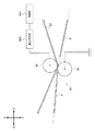
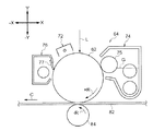
図8に示されるように、画像形成装置10は、上下方向(Y方向)の下側から上側へ向けて、記録媒体の一例としてのシート部材Pが収容される用紙収容部12と、用紙収容部12の上側に配置され用紙収容部12から供給されるシート部材Pに画像形成を行う主動作部14と、主動作部14の上側に設けられ原稿(図示省略)を読み取る原稿読取部16と、各部へシート部材Pを搬送する搬送部18と、主動作部14内に設けられ画像形成装置10の各部の動作を制御する主制御部20と、を含んで構成されている。そして、画像形成装置10は、複数のフレーム部材で構成された筐体としての装置本体10Aを備えている。
(overall structure)
As shown in FIG. 8, the
〔用紙収容部〕
用紙収容部12は、サイズの異なるシート部材Pを収容可能な第1収容部22、第2収容部24、第3収容部26、及び第4収容部28を備えている。第1収容部22、第2収容部24、第3収容部26、及び第4収容部28は、収容されたシート部材Pを一枚ずつ送り出す送り出しロール32と、送り出されたシート部材Pを画像形成装置10内に設けられた搬送路30に搬送する搬送ロール34と、を備えている。
[Paper compartment]
The
〔搬送部〕
搬送部18は、搬送ロール34に対して搬送路30の下流側に配置され、シート部材Pを一枚ずつ搬送する複数の搬送ロール36を備えている。さらに、シート部材Pの搬送方向で搬送ロール36に対して搬送路30の下流側には、シート部材Pを一端停止させると共に、決められたタイミングで後述する二次転写位置へシート部材Pを送り出すことで画像転写の位置合せを行う位置合せロール38が配置されている。
[Transport section]
The
搬送路30の上流側部分は、画像形成装置10の正面視において、矢印Y方向に向けて用紙収容部12の−X方向側から主動作部14の−X方向側下部まで直線状とされている。また、搬送路30の下流側部分は、主動作部14の−X方向側下部から主動作部14のX方向側下部に設けられた排紙部13まで延びている。
The upstream portion of the
さらに、搬送路30には、シート部材Pの両面に画像形成を行うためにシート部材Pが搬送及び反転される両面搬送路31が接続されている。なお、両面搬送を行わないときのシート部材Pの搬送方向は、矢印Aで示されている。
Further, a double-
両面搬送路31は、画像形成装置10の正面視において、主動作部14のX方向側下部から用紙収容部12のX方向側まで矢印Y方向に直線状に設けられた反転部33と、反転部33に搬送されたシート部材Pの後端が進入するとともに図示の−X方向側(矢印Bで示す)にシート部材Pを搬送する搬送部35とを備えている。そして、搬送部35の下流側端部は、搬送路30の位置合せロール38よりも上流側に案内部材(図示省略)により接続されている。なお、図8において、搬送路30と両面搬送路31との切り替えを行う切替部材、及び反転部33と搬送部35との切り替えを行う切替部材については図示を省略する。
The double-
〔原稿読取部〕
原稿読取部16は、複数の原稿(図示省略)を置くことが可能な原稿置台41と、一枚の原稿が載せられるプラテンガラス42と、プラテンガラス42に載せられた原稿を読み取る原稿読取装置44と、読み取られた原稿が排出される原稿排出部43と、を備えている。
[Original reading section]
The
原稿読取装置44は、プラテンガラス42に載せられた原稿に光を照射する光照射部46と、光照射部46によって照射され原稿から反射された反射光をプラテンガラス42と平行な方向に反射させて折り返す1個のフルレートミラー48及び2個のハーフレートミラー52と、フルレートミラー48及びハーフレートミラー52によって折り返された反射光が入射する結像レンズ54と、結像レンズ54によって結像された反射光を電気信号に変換する光電変換素子56と、備えている。
The
光電変換素子56によって変換された電気信号は、画像処理装置(図示省略)で画像処理され画像形成に用いられるようになっている。また、フルレートミラー48は、プラテンガラス42に沿ってフルレートで移動し、ハーフレートミラー52は、プラテンガラス42に沿ってハーフレートで移動するようになっている。
The electric signal converted by the
〔主動作部〕
主動作部14は、シート部材P上にトナー画像を形成する画像形成部60と、画像形成部60によって形成されたシート部材P上に形成されたトナー画像を熱と圧力によりシート部材Pに定着する定着装置100と、を備えている。
[Main operation part]
The
[画像形成部]
画像形成部60は、イエロー(Y)、マゼンタ(M)、シアン(C)、及び ブラック(K)の各トナーに対応した像保持体62K、62C、62M、62Yを備える画像形成ユニット64K、64C、64M、64Yと、像保持体62K、62C、62M、62Yの外周面に向けて光ビームLを出射して露光を行う露光ユニット66K、66C、66M、66Yと、画像形成ユニット64K、64C、64M、64Yで形成されたトナー画像をシート部材P上に転写する転写ユニット68と、を含んで構成されている。
[Image forming unit]
The
なお、以後の説明では、Y、M、C、Kを区別する必要がある場合は、数字の後にY、M、C、Kのいずれかの英字を付して説明し、同様の構成でY、M、C、Kを区別する必要がない場合は、Y、M、C、Kの記載を省略する。 In the following description, if it is necessary to distinguish Y, M, C, and K, an alphabetic letter Y, M, C, or K will be added after the numeral, and the same configuration will be used. , M, C, and K need not be distinguished from each other, description of Y, M, C, and K is omitted.
[露光ユニット(画像形成部)]
露光ユニット66は、光源(図示省略)から出射された光ビームを回転多面鏡(ポリゴンミラー:符号無し)で走査すると共に反射ミラーを含む複数の光学部品で反射して、各色のトナーに対応した光ビームLを像保持体62へ向けて出射する構成となっている。また、像保持体62は、露光ユニット66の下方側(−Y方向側)に設けられている。
[Exposure unit (image forming unit)]
The exposure unit 66 scans a light beam emitted from a light source (not shown) with a rotating polygon mirror (polygon mirror: unsigned) and reflects it with a plurality of optical components including a reflection mirror to correspond to each color toner. The light beam L is emitted toward the
[画像形成ユニット(画像形成部)]
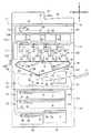
図7に示されるように、画像形成ユニット64は、矢印+R方向(図示の時計回り方向)に回転可能とされた円柱状の像保持体62と、像保持体62の外周面と対向して回転方向の上流側から下流側へ順に配置された帯電器72、現像器74、及びクリーニング部材76と、を含んで構成されている。
[Image forming unit (image forming unit)]
As shown in FIG. 7, the
そして、帯電器72と現像器74は、像保持体62の外周面で帯電器72と現像器74との間の位置に光ビームLが照射されるように配置されている。また、像保持体62の外周面で現像器74とクリーニング部材76との間の位置には、後述する中間転写ベルト82が接触している。
The charging
像保持体62は、モータ(図示省略)の駆動により矢印+R方向に回転可能となっている。また、帯電器72は、一例として、ワイヤに電圧を印加してコロナ放電により像保持体62の外周面をトナーと同極性に帯電させるコロトロン方式の帯電手段で構成されている。ここで、帯電した像保持体62の外周面に画像データに基づいて光ビームLが照射されることで、潜像(静電潜像)が形成されるようになっている。
The
現像器74は、一例として、磁性体からなるキャリア粒子とマイナスに帯電したトナーが混合された現像剤Gを収容しており、周方向に複数の磁極を有するマグネットロール(図示省略)が内側に設けられた円筒状の現像スリーブ75が設けられている。そして、現像器74は、現像スリーブ75が回転することにより像保持体62と対向する部位で磁気ブラシを形成する。さらに、現像器74は、電圧印加手段(図示省略)によって現像スリーブ75に現像バイアスが印加されることで、像保持体62の外周面の潜像をトナーで顕在化させてトナー画像(現像剤像)を形成するようになっている。なお、各現像器74には、画像形成部60の上方に設けられた各トナーカートリッジ79(図8参照)からトナーが供給されるようになっている。
As an example, the developing
クリーニング部材76は、像保持体62の外周面と接触するクリーニングブレード77を備えており、像保持体62の外周面に残留したトナーをクリーニングブレード77で掻き落として回収するようになっている。また、像保持体62の回転方向で現像器74よりも下流側には、現像器74で現像されたトナー画像が一次転写される中間転写ベルト82が設けられている。
The cleaning
[転写ユニット(画像形成部)]
図8に示されるように、転写ユニット68は、無端状の中間転写ベルト82と、像保持体62から中間転写ベルト82上にトナー画像を一次転写させる一次転写ロール84と、中間転写ベルト82上で順次重ねられたトナー画像をシート部材Pへ二次転写させる転写部材の一例としての二次転写ロール86と、を含んで構成されている。さらに、中間転写ベルト82を挟んで二次転写ロール86の反対側には、補助ロール88が配置されている。
[Transfer unit (image forming unit)]
As shown in FIG. 8, the
また、中間転写ベルト82の内側には、回転駆動される駆動ロール92と、回転可能に備えられた複数の搬送ロール94とが配置されている。そして、この中間転写ベルト82は、一次転写ロール84K、84C、84M、84Y、駆動ロール92、搬送ロール94、及び補助ロール88に巻き掛けられている。これにより、中間転写ベルト82は、駆動ロール92が図示の反時計周りに回転すると、矢印C方向(図示の反対時計回り方向)に周回移動するようになっている。
Inside the
一次転写ロール84は、一例として、ステンレス鋼などの金属で構成された円柱状のシャフトの周囲に弾性層(図示省略)が形成された構成となっており、シャフトの両端部がベアリングで支持されることにより回転可能となっている。また、一次転写ロール84は、電源(図示省略)からシャフトにトナーの極性とは逆極性の電圧(正の電圧)が印加されるようになっている。
As an example, the
二次転写ロール86は、電子導電性の材料又はイオン電導性の材料によって形成されたロール材から構成されており、搬送路30における位置合せロール38の下流側に配置され、回転可能とされている。
The
そして、図1に示されるように、二次転写ロール86は接地されている。また、補助ロール88は、二次転写ロール86の対向電極を形成しており、後述する電圧印加部102によって補助ロール88に二次転写電圧が印加されるようになっている。
As shown in FIG. 1, the
補助ロール88に二次転写電圧(負の電圧)が印加され、補助ロール88と二次転写ロール86との間に電位差が生じるので、二次転写ロール86と中間転写ベルト82との挟持部に搬送されるシート部材P上に中間転写ベルト82上のトナー画像が二次転写されるようになっている。
Since a secondary transfer voltage (negative voltage) is applied to the
換言すれば、補助ロール88に二次転写電圧(負の電圧)が印加されることで、二次転写ロール86に二次転写電圧(正の電圧)が印加され、補助ロール88と二次転写ロール86との間に電位差が生じる。これにより、シート部材P上に中間転写ベルト82上のトナー画像が二次転写されるようになっている。
In other words, by applying a secondary transfer voltage (negative voltage) to the
なお、補助ロール88に印加される電圧等については、詳細を後述する。
Details of the voltage applied to the
さらに、二次転写ロール86に対いてシート部材Pの搬送方向の下流側には、図8に示されるように、トナー画像の二次転写が終了したシート部材Pを定着装置100へ搬送する搬送ベルト96が設けられている。搬送ベルト96は、支持ロール97と駆動ロール98とに巻きかけられ、定着装置100へシート部材Pを搬送するように周回移動するようになっている。
Further, on the downstream side in the conveyance direction of the sheet member P with respect to the
(全体構成の作用)
次に、本実施形態の作用について説明する。
(Operation of the overall configuration)
Next, the operation of this embodiment will be described.
シート部材Pに画像を形成する場合には、図7に示されるように、像保持体62が帯電器72によって帯電されると共に、画像データに応じて露光ユニット66(図8参照)から出射された光ビームLによって露光され、像保持体62に静電潜像が形成される。
When an image is formed on the sheet member P, as shown in FIG. 7, the
続いて、夫々の像保持体62の外周面に形成された静電潜像は、現像器74によって、それぞれイエロー(Y)、マゼンタ(M)、シアン(C)、黒(K)の各色のトナー画像として現像される。
Subsequently, the electrostatic latent images formed on the outer peripheral surfaces of the
さらに、各像保持体62の表面に形成された各トナー画像は、一次転写位置で、各一次転写ロール84によって中間転写ベルト82上に順次、多重転写される。そして、中間転写ベルト82上に多重転写されたトナー画像は、図8に示されるように、二次転写位置で、搬送路30を搬送されてきたシート部材P上に二次転写ロール86及び補助ロール88によって二次転写される。
Further, each toner image formed on the surface of each
続いて、トナー画像が転写されたシート部材Pは、搬送ベルト96により定着装置100に向けて搬送される。そして、定着装置100では、シート部材P上のトナー画像が加熱、加圧されることで定着される。トナー画像が定着されたシート部材Pは、一例として、排紙部13に排出される。このようにして、一連の画像形成工程が行われる。
Subsequently, the sheet member P to which the toner image has been transferred is conveyed toward the fixing
なお、画像が形成されていない非画像面にトナー画像を形成する場合(両面画像形成の場合)は、定着装置100で表面に画像定着を行った後、シート部材Pを両面搬送路31に送り込んで裏面の画像形成及び定着を行う。
When a toner image is formed on a non-image surface on which no image is formed (in the case of double-sided image formation), after fixing the image on the surface with the fixing
(要部構成)
次に、補助ロール88に印加される電圧等について説明する。
(Main part configuration)
Next, the voltage applied to the
前述したように二次転写ロール86は、図1に示されるように、二次転写ロール86のシャフト(図示省略)において接地されている。また、負極に帯電したトナーで構成されるトナー画像をシート部材Pに二次転写させるため、補助ロール88に電圧を印加する電圧印加部材の一例としての電圧印加部102が備えられている。さらに、電圧印加部102を制御して、電圧印加部102によって補助ロール88に印加される電圧を変える制御部104が備えられている。
As described above, the
そして、中間転写ベルト82上のトナー画像をシート部材Pに二次転写させる場合には、制御部104が、電圧印加部102を制御して補助ロール88に負の電圧(二次転写電圧、以下「転写電圧」と記載する)を印加するようになっている。一方、トナー画像をシート部材Pに転写させる必要がない場合には、転写電圧による二次転写ロール86の抵抗上昇を抑制するため、制御部104が、電圧印加部102を制御して補助ロール88に転写電圧に対して逆極性となる正の電圧(逆極性電圧)を印加するようになっている。
When the toner image on the
転写電圧を補助ロール88に印加することで、前述したように、二次転写ロール86に転写電圧(正の電圧)が印加される。この転写電圧により、二次転写ロール86を構成する部材に含まれるイオンが偏在し、二次転写ロール86の抵抗が上昇する。補助ロール88に逆極性電圧を印加することで、二次転写ロール86におけるイオンの偏在を戻し、二次転写ロール86の抵抗上昇を抑制するようになっている。
By applying the transfer voltage to the
〔転写電圧・逆極性電圧の印加時期〕
次に、補助ロール88に転写電圧が印加される時期と、補助ロール88に逆極性電圧が印加される時期とについて詳細に説明する。
[Application timing of transfer voltage and reverse polarity voltage]
Next, the timing when the transfer voltage is applied to the
補助ロール88に転写電圧を印加する時期については、回転する二次転写ロール86と搬送されるシート部材Pとが接触している間である。
The timing for applying the transfer voltage to the
一方、補助ロール88に逆極性電圧を印加する時期については、一の印刷ジョブにおける前後と、搬送されるシート部材Pとシート部材Pとの間とである。
On the other hand, the timing of applying the reverse polarity voltage to the
具体的には、一の印刷ジョブにおいて最初に搬送される(最初に画像が転写される)シート部材Pに二次転写ロール86が接触する前と、最後に搬送される(画像が転写される)シート部材Pから二次転写ロール86が離間した後とである。
Specifically, before the
さらに、一の印刷ジョブによって複数枚のシート部材Pに画像を形成する場合には、搬送されるシート部材Pとシート部材Pとの間、つまり、二次転写ロール86とシート部材Pとが離間している間である。
Further, when an image is formed on a plurality of sheet members P by one print job, the sheet member P being conveyed and the sheet member P, that is, the
以下図を用いて説明する。 This will be described below with reference to the drawings.
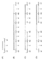
図2(A)には、一の印刷ジョブによって1枚のシート部材Pに画像が形成される場合について、転写電圧を印加する時期と、逆極性電圧を印加する時期とについて示されている。二次転写ロール86(図1参照)とシート部材Pとが接触している時期(図中の時期R)で、補助ロール88に転写電圧が印加されるようになっている。一方、一の印刷ジョブにおける前後の予め定められた時期(図中の時期M1)で、補助ロール88に逆極性電圧が印加されるようになっている。なお、時期M1は時期Rより短い時間とされている。
FIG. 2A shows the timing of applying the transfer voltage and the timing of applying the reverse polarity voltage when an image is formed on one sheet member P by one print job. The transfer voltage is applied to the
図2(B)には、一の印刷ジョブによって5枚のシート部材Pに画像が形成される場合、図2(C)には、一の印刷ジョブによって10枚のシート部材Pに画像が形成される場合、図2(D)には、一の印刷ジョブによって50枚のシート部材Pに画像が形成される場合が示されている。 In FIG. 2B, when an image is formed on five sheet members P by one print job, in FIG. 2C, an image is formed on ten sheet members P by one print job. In this case, FIG. 2D shows a case where an image is formed on 50 sheet members P by one print job.
図2(B)(C)(D)に示されるように、一の印刷ジョブによって複数枚のシート部材Pに画像を形成する場合には、搬送されるシート部材Pとシート部材Pとの間で二次転写ロール86がシート部材Pから離間する時期(図中の時期M2)で、時期M1と同様に、補助ロール88に逆極性電圧が印加されるようになっている。
As shown in FIGS. 2B, 2 </ b> C, and 2 </ b> D, when an image is formed on a plurality of sheet members P by a single print job, a space between the conveyed sheet members P and the sheet members P is used. Thus, at the time when the
しかし、一の印刷ジョブを短時間で終了させるため(生産性を向上させるため)、シート部材P間の距離は、一の印刷ジョブの前後で二次転写ロール86がシート部材Pと離れる距離と比して、短くなっている。つまり、時期M2で補助ロール88に逆極性電圧が印加される時間は、時期M1で補助ロール88に逆極性電圧が印加される時間より短くなっている。
However, in order to finish one print job in a short time (in order to improve productivity), the distance between the sheet members P is the distance that the
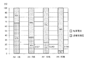
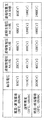
図3には、一の印刷ジョブで、補助ロール88(図1参照)に転写電圧を印加する時間(時期Rの時間)と逆極性電圧を印加する時間(時期M1及びM2の時間)との比率が棒グラフで記載されている。図3に示されるように、一の印刷ジョブで1枚のA4のシート部材Pに画像を形成する場合は、一の印刷ジョブに費やされる時間の割合を100%とすると、転写電圧を印加する時間の割合が33%で、逆極性電圧を印加する時間の割合が67%となる。 FIG. 3 shows the time for applying the transfer voltage (time R) to the auxiliary roll 88 (see FIG. 1) and the time for applying the reverse polarity voltage (time M1 and M2) in one print job. The ratio is shown as a bar graph. As shown in FIG. 3, when an image is formed on one A4 sheet member P in one print job, a transfer voltage is applied assuming that the percentage of time spent in one print job is 100%. The percentage of time is 33%, and the percentage of time to apply the reverse polarity voltage is 67%.
また、一の印刷ジョブで夫々5枚、10枚、50枚と画像が形成されるA4のシート部材Pを増やすと、一の印刷ジョブで1枚のA4のシート部材Pに画像を形成する際に費やされる時間の割合を100%とする場合に、逆極性電圧を印加する時間の割合が、徐々に少なくなる。一の印刷ジョブの枚数が増えることで、転写電圧を印加している時間が長くなる一方、時期M1によって逆極性電圧を印加する回数は変わらないからである。 In addition, when the number of A4 sheet members P on which images are formed as 5 sheets, 10 sheets, and 50 sheets respectively in one print job is increased, an image is formed on one A4 sheet member P in one print job. When the ratio of the time spent for 100% is 100%, the ratio of the time for applying the reverse polarity voltage gradually decreases. This is because as the number of print jobs increases, the time during which the transfer voltage is applied becomes longer, while the number of times the reverse polarity voltage is applied does not change depending on the timing M1.
具体的には、一の印刷ジョブで1枚のA4のシート部材Pに画像を形成する場合に逆極性電圧を印加する割合を1とすると、一の印刷ジョブで夫々5枚、10枚、50枚のA4のシート部材Pに画像を形成する場合の割合は、0.537、0.343、0.089となる。 Specifically, when an image is formed on one A4 sheet member P in one print job, assuming that the ratio of applying the reverse polarity voltage is 1, 5 sheets, 10 sheets, and 50 respectively in one print job. The ratios for forming an image on the A4 sheet member P are 0.537, 0.343, and 0.089.
〔逆極性電圧の大小〕
次に、各印刷ジョブ間での逆極性電圧の大小について説明する。
[Reverse polarity voltage magnitude]
Next, the magnitude of the reverse polarity voltage between print jobs will be described.
前述したように、一の印刷ジョブにおけるシート部材Pの枚数が多いほど、補助ロール88に逆極性電圧を印加する時間の割合が少なくなる。そのため、二次転写ロール86を構成する部材に含まれるイオンが偏在し、一の印刷ジョブで画像が形成される枚数が多いほど、二次転写ロール86の抵抗(電気抵抗)が上昇してしまうことが考えられる。
As described above, as the number of sheet members P in one print job increases, the proportion of time for applying the reverse polarity voltage to the
これに対して、制御部104は、一の印刷ジョブによって画像が転写されるシート部材Pの枚数に基づいて、補助ロール88に印加する逆極性電圧の大小を制御するようになっている。具体的に、制御部104は、一の印刷ジョブによって画像が転写されるシート部材Pの枚数が多い場合は、少ない場合と比して、補助ロール88に印加する逆極性電圧が大きくなるように電圧印加部102を制御するようになっている。
In contrast, the
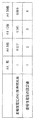
一例として、図4に示されるように、一の印刷ジョブで1枚のA4のシート部材Pに画像を形成する場合の逆極性電圧の大きさを1とすると、一の印刷ジョブで夫々5枚、10枚、50枚のA4のシート部材Pに画像を形成する場合には、逆極性電圧の大きさは、2、3、4とされる。これは、一の印刷ジョブで1枚のA4のシート部材Pに画像を形成する場合を1とした場合に対して、一の印刷ジョブで夫々複数枚のA4のシート部材Pに画像を形成する場合の割合を考慮したものである(図4の中段:逆極性電圧の印加時間比率)。 As an example, as shown in FIG. 4, when an image is formed on one A4 sheet member P in one print job, assuming that the magnitude of the reverse polarity voltage is 1, 5 sheets each in one print job. When an image is formed on 10 or 50 A4 sheet members P, the magnitude of the reverse polarity voltage is set to 2, 3, and 4. This is because when an image is formed on one A4 sheet member P in one print job, an image is formed on a plurality of A4 sheet members P in one print job. This is a case ratio (middle stage in FIG. 4: application time ratio of reverse polarity voltage).
なお、一の印刷ジョブで50枚のA4のシート部材Pに画像を形成する場合については、逆極性電圧の印加時間比率を考慮すると、補助ロール88に印加する逆極性電圧は、4ではなく11になってしまう。このように、補助ロール88に印加される逆極性電圧の大きさを11にしてしまうと、二次転写ロール86と接触する中間転写ベルト82に生じる放電生成物の量が多くなる。このため、一の印刷ジョブで50枚のA4のシート部材Pに画像を形成する場合の逆極性電圧の大きさについては、放電生成物の量が多くならないように4とした。
In the case of forming an image on 50 A4 sheet members P in one print job, the reverse polarity voltage applied to the
図6には、比較例に係る画像形成装置の二次転写ロールの抵抗上昇と、本実施形態に係る二次転写ロール86の抵抗上昇とについて示されている。
FIG. 6 shows an increase in resistance of the secondary transfer roll of the image forming apparatus according to the comparative example and an increase in resistance of the
一の印刷ジョブで1枚のA4のシート部材Pに画像を形成する際には、二次転写ロール86の抵抗上昇値は、0.21〔LogΩ〕であった。一の印刷ジョブで5枚のA4のシート部材Pに画像を形成する際に、逆極性電圧を変えなかった比較例に係る画像形成装置の二次転写ロールの抵抗上昇値は、0.37〔LogΩ〕であった。
When an image was formed on one A4 sheet member P in one print job, the resistance increase value of the
一方、前述したように、一の印刷ジョブで5枚のA4のシート部材Pに画像を形成する際に、逆極性電圧を大きくした本実施形態に係る画像形成装置10の二次転写ロール86の抵抗上昇値は、0.20〔LogΩ〕であった。このように、一の印刷ジョブで1枚のA4のシート部材Pに画像を形成する際と同様となった。
On the other hand, as described above, when forming an image on the five A4 sheet members P in one print job, the reverse transfer voltage of the
以上説明したように、一の印刷ジョブによって画像が転写されるシート部材Pの枚数が多い場合は、少ない場合と比して、逆極性電圧を大きくすることで、二次転写ロール86の抵抗上昇が抑制されることが分かる。
As described above, when the number of sheet members P onto which an image is transferred by one print job is large, the resistance of the
さらに、制御部104は、装置本体10Aの周囲の環境温度及び環境湿度に基づいて電圧印加部102を制御し、補助ロール88に印加する逆極性電圧を変えるようになっている。画像形成装置10には、装置本体10Aの周囲の環境温度を検知する温度検知部材の一例としての温度センサ106と、周囲の環境湿度を検知する湿度検知部材の一例としての湿度センサ108とが備えられている(図8参照)。
Further, the
具体的には、温度センサ106及び湿度センサ108によって検知された装置本体10Aの周囲の環境温度及び環境湿度が、通常環境(温度22〔℃〕、湿度55%RH)に対して、高温高湿の場合は、制御部104は、通常環境の場合と比して、補助ロール88に印加する逆極性電圧が小さくなるように電圧印加部102を制御する。一方、環境温度及び環境湿度が、通常環境に対して、低温低湿の場合は、制御部104は、通常環境の場合と比して、補助ロール88に印加する逆極性電圧が大きくなるように電圧印加部102を制御するようになっている。
Specifically, the ambient temperature and ambient humidity around the apparatus
これは、環境温度及び環境湿度が、通常環境に対して、高温高湿の場合は、二次転写ロール86の抵抗値が通常環境の場合と比して低くなる。一方、環境温度及び環境湿度が、通常環境に対して、低温低湿の場合は、二次転写ロール86の抵抗値が通常環境の場合と比して高くなる。これにより、制御部104が、二次転写ロール86と補助ロール88との間に流れる転写に必要な電流が同じになるように、補助ロール88に印加される転写電圧を変えるからである。
This is because the resistance value of the
一例として、補助ロール88に印加される転写電圧については、図5に示されるように、通常環境の場合に1500〔V〕であるのに対し、高温高湿環境(温度28〔℃〕、湿度85%RH)の場合に500〔V〕とされ、低温低湿環境(温度10〔℃〕、湿度15%RH)の場合に3000〔V〕とされる。
As an example, as shown in FIG. 5, the transfer voltage applied to the
これに対して、補助ロール88に印加される逆極性電圧については、一の印刷ジョブで1枚のA4のシート部材Pに画像を形成する際には、通常環境の場合に400〔V〕であるのに対し、高温高湿環境の場合に200〔V〕とされ、低温低湿環境の場合に600〔V〕とされる。また、一の印刷ジョブで夫々5枚、10枚、50枚のA4のシート部材Pに画像を形成する際には、前述した係数(2、3、4)が、一の印刷ジョブで1枚のA4のシート部材Pに画像を形成する際の逆極性電圧に乗される。
On the other hand, the reverse polarity voltage applied to the
(まとめ)
以上説明したように、制御部104は、一の印刷ジョブによって画像が転写されるシート部材Pの枚数が多い場合は、少ない場合に比して、補助ロール88に印加される逆極性電圧を大きくする。これにより、夫々の印刷ジョブ間で画像を形成するシート部材Pの枚数が異なる場合であっても、シート部材Pの枚数に係らず同様の逆極性電圧を印加する場合と比して、二次転写ロール86の抵抗上昇が抑制される。
(Summary)
As described above, the
また、一の印刷ジョブによって画像が転写されるシート部材Pの枚数が多い場合に少ない場合に比して逆極性電圧を大きくするため、逆極性電圧を常に大きくする場合と比して、二次転写ロール86と接触する中間転写ベルト82等に生じる放電生成物の量が抑制される。
Further, since the reverse polarity voltage is increased when the number of sheet members P to which an image is transferred by one print job is large, the secondary polarity voltage is increased as compared with the case where the reverse polarity voltage is always increased. The amount of discharge products generated on the
また、環境温度及び環境湿度によって二次転写ロール86の抵抗値が変わるため、補助ロール88に印加される転写電圧が変わる。そして、制御部104は、環境温度及び環境湿度が、通常環境に対して高温高湿の場合は、逆極性電圧を小さくし、通常環境に対して低温低湿の場合は、逆極性電圧を大きくする。これにより、環境温度及び環境湿度に係らず同様の逆極性電圧を印加する場合と比して、二次転写ロール86の抵抗上昇が効果的に抑制される。
Further, since the resistance value of the secondary transfer roll 86 changes depending on the environmental temperature and the environmental humidity, the transfer voltage applied to the
また、二次転写ロール86の抵抗上昇が抑制されるため、二次転写ロール86の抵抗上昇が抑制されない場合と比して、二次転写ロール86の寿命が延びる。
Further, since the increase in resistance of the
なお、本発明を特定の実施形態について詳細に説明したが、本発明はかかる実施形態に限定されるものではなく、本発明の範囲内にて他の種々の実施形態が可能であることは当業者にとって明らかである。例えば、上記実施形態では、補助ロール88に転写電圧(負の電圧)が印加されることで、二次転写ロール86に転写電圧(正の電圧)が印加されたが、二次転写ロール86に直接転写電圧を印加してもよい。
Although the present invention has been described in detail with respect to specific embodiments, the present invention is not limited to such embodiments, and various other embodiments are possible within the scope of the present invention. It is clear to the contractor. For example, in the embodiment described above, the transfer voltage (positive voltage) is applied to the
また、上記実施形態では、搬送されるシート部材Pとシート部材Pとの間の時期M2でも、時期M1と同様に、補助ロール88に逆極性電圧を印加したが特に時期M2で補助ロール88に逆極性電圧を印加しなくてもよい。
In the above embodiment, the reverse polarity voltage is applied to the
また、上記実施形態では、環境温度及び環境湿度が、通常環境に対して高温高湿又は低温低湿の場合に、逆極性電圧を変えたが、環境温度が、通常温度(温度22〔℃〕)に対して高温の場合に、逆極性電圧を小さくし、通常温度に対して低温の場合に、逆極性電圧を大きくしてもよい。これにより、環境温度に係らず同様の逆極性電圧を印加する場合と比して、二次転写ロール86の抵抗上昇が効果的に抑制される。
In the above embodiment, the reverse polarity voltage is changed when the environmental temperature and the environmental humidity are high temperature and high humidity or low temperature and low humidity with respect to the normal environment. However, the environmental temperature is the normal temperature (temperature 22 [° C.]). In contrast, the reverse polarity voltage may be decreased when the temperature is high, and the reverse polarity voltage may be increased when the temperature is low compared to the normal temperature. Thereby, compared with the case where the same reverse polarity voltage is applied regardless of the environmental temperature, the resistance increase of the
また、上記実施形態では、環境温度及び環境湿度が、通常環境に対して高温高湿又は低温低湿の場合に、逆極性電圧を変えたが、環境湿度が、通常湿度(湿度55%RH)に対して高湿の場合に、逆極性電圧を小さくし、通常湿度に対して低湿の場合に、逆極性電圧を大きくしてもよい。これにより、環境湿度に係らず同様の逆極性電圧を印加する場合と比して、二次転写ロール86の抵抗上昇が効果的に抑制される。
In the above embodiment, the reverse polarity voltage is changed when the environmental temperature and the environmental humidity are high temperature and high humidity or low temperature and low humidity with respect to the normal environment. However, the environmental humidity is changed to normal humidity (humidity 55% RH). On the other hand, the reverse polarity voltage may be decreased when the humidity is high, and the reverse polarity voltage may be increased when the humidity is low relative to the normal humidity. Thereby, compared with the case where the same reverse polarity voltage is applied irrespective of environmental humidity, the resistance increase of the
また、上記実施形態では、中間転写ベルト82からシート部材Pにトナー画像が転写される場合を例にとって説明したが、像保持体からシート部材Pにトナー画像が転写される場合(直接転写)に本願構成を用いてもよい。
In the above embodiment, the toner image is transferred from the
また、上記実施形態では、A4のシート部材Pを用いて説明したが、A3のシート部材Pに画像を形成させる印刷ジョブでは、A4換算の枚数にして逆極性電圧の大きさを決めてもよい。 In the above embodiment, the A4 sheet member P has been described. However, in a print job for forming an image on the A3 sheet member P, the reverse polarity voltage may be determined by the number of sheets converted to A4. .
また、上記実施形態では、転写電圧と逆極性電圧とを一つの電圧印加部102が補助ロール88に印加したが、転写電圧と逆極性電圧とで電圧を印加する部材を分けてもよい。
In the above embodiment, the transfer voltage and the reverse polarity voltage are applied to the
10 画像形成装置
10A 装置本体
86 二次転写ロール(転写部材の一例)
102 電圧印加部(電圧印加部材の一例)
104 制御部
106 温度センサ(温度検知部材の一例)
107 湿度センサ(湿度検知部材の一例)
DESCRIPTION OF
102 Voltage application part (an example of a voltage application member)
104
107 Humidity sensor (an example of humidity detection member)
Claims (3)
一の印刷ジョブによって画像が転写される記録媒体の枚数が多い場合は、少ない場合と比して、前記転写部材に印加される逆極性電圧が大きくなるように電圧印加部材を制御する制御部と、
を備える画像形成装置。 When transferring the image to the transported recording medium, a transfer voltage for transferring the image to the recording medium is applied by the voltage applying member, and in one print job, the image is first transferred to the recording medium to which the image is transferred. A transfer member to which a reverse polarity voltage having a polarity opposite to the transfer voltage is applied by a voltage application member before transfer and after the image is transferred to a recording medium to which the image is finally transferred;
A control unit that controls the voltage application member so that the reverse polarity voltage applied to the transfer member is larger when the number of recording media onto which an image is transferred by one print job is larger than when the number of recording media is small; ,
An image forming apparatus comprising:
前記制御部は、前記温度検知部材の検知結果に基づき、検知温度が低い場合は、高い場合と比して、前記転写部材に印加される逆極性電圧が大きくなるように前記電圧印加部材を制御する請求項1に記載の画像形成装置。 A temperature detection member that detects the ambient temperature around the device body is provided.
The control unit controls the voltage application member based on the detection result of the temperature detection member so that the reverse polarity voltage applied to the transfer member is larger when the detection temperature is low than when the detection temperature is high. The image forming apparatus according to claim 1.
前記制御部は、前記湿度検知部材の検知結果に基づき、検知湿度が低い場合は、高い場合と比して、前記転写部材に印加される逆極性電圧が大きくなるように前記電圧印加部材を制御する請求項1又は2に記載の画像形成装置。 Humidity detection member that detects the environmental humidity around the device body is provided,
The control unit controls the voltage application member based on the detection result of the humidity detection member such that when the detected humidity is low, the reverse polarity voltage applied to the transfer member is higher than when the humidity is high. The image forming apparatus according to claim 1.
Priority Applications (1)
| Application Number | Priority Date | Filing Date | Title |
|---|---|---|---|
| JP2013029138A JP5994672B2 (en) | 2013-02-18 | 2013-02-18 | Image forming apparatus |
Applications Claiming Priority (1)
| Application Number | Priority Date | Filing Date | Title |
|---|---|---|---|
| JP2013029138A JP5994672B2 (en) | 2013-02-18 | 2013-02-18 | Image forming apparatus |
Publications (2)
| Publication Number | Publication Date |
|---|---|
| JP2014157334A JP2014157334A (en) | 2014-08-28 |
| JP5994672B2 true JP5994672B2 (en) | 2016-09-21 |
Family
ID=51578217
Family Applications (1)
| Application Number | Title | Priority Date | Filing Date |
|---|---|---|---|
| JP2013029138A Expired - Fee Related JP5994672B2 (en) | 2013-02-18 | 2013-02-18 | Image forming apparatus |
Country Status (1)
| Country | Link |
|---|---|
| JP (1) | JP5994672B2 (en) |
Families Citing this family (2)
| Publication number | Priority date | Publication date | Assignee | Title |
|---|---|---|---|---|
| JP2017040671A (en) * | 2015-08-17 | 2017-02-23 | 富士ゼロックス株式会社 | Transfer device and image formation apparatus |
| JP6906964B2 (en) * | 2017-01-26 | 2021-07-21 | キヤノン株式会社 | Image forming device |
Family Cites Families (3)
| Publication number | Priority date | Publication date | Assignee | Title |
|---|---|---|---|---|
| JP4150873B2 (en) * | 1999-10-21 | 2008-09-17 | 富士ゼロックス株式会社 | Image forming apparatus |
| JP2006091368A (en) * | 2004-09-22 | 2006-04-06 | Canon Inc | Image forming apparatus |
| JP5015475B2 (en) * | 2006-02-28 | 2012-08-29 | 株式会社東芝 | Image forming apparatus and image forming method |
-
2013
- 2013-02-18 JP JP2013029138A patent/JP5994672B2/en not_active Expired - Fee Related
Also Published As
| Publication number | Publication date |
|---|---|
| JP2014157334A (en) | 2014-08-28 |
Similar Documents
| Publication | Publication Date | Title |
|---|---|---|
| JP5671848B2 (en) | Image forming apparatus | |
| JP2002318482A (en) | Image forming apparatus | |
| JP6071256B2 (en) | Image forming apparatus | |
| JP2009163030A (en) | Image forming apparatus and drive control method thereof | |
| JP5929893B2 (en) | Image forming apparatus and fixing device | |
| JP5380484B2 (en) | Image forming apparatus | |
| JP2015060122A (en) | Image forming apparatus | |
| US10802425B2 (en) | Image forming apparatus | |
| JP5994672B2 (en) | Image forming apparatus | |
| US9429880B2 (en) | Transfer device and image forming apparatus | |
| JP2004294889A (en) | Image forming apparatus | |
| JP2014059507A (en) | Image forming apparatus | |
| JP5971161B2 (en) | Fixing device Image forming device | |
| JP6075108B2 (en) | Image forming apparatus | |
| JP5822785B2 (en) | Image forming apparatus | |
| JP2013092734A (en) | Image forming apparatus | |
| JP2014185675A (en) | Transfer roll, fixation device, and image formation apparatus | |
| JP6554854B2 (en) | Conveying device, cooling device, and image forming apparatus | |
| JP2015106021A (en) | Conveyance device, cooling device, and image forming apparatus | |
| JP6075202B2 (en) | Transfer device and image forming apparatus | |
| JP2020042148A (en) | Image forming device | |
| JP2009098452A (en) | Image forming apparatus | |
| JP7157371B2 (en) | CHARGING DEVICE, PROCESS CARTRIDGE, AND IMAGE FORMING APPARATUS | |
| JP4862488B2 (en) | Image forming apparatus | |
| JP6131748B2 (en) | Power feeding structure, charging device, image forming apparatus |
Legal Events
| Date | Code | Title | Description |
|---|---|---|---|
| A621 | Written request for application examination |
Free format text: JAPANESE INTERMEDIATE CODE: A621 Effective date: 20150306 |
|
| A131 | Notification of reasons for refusal |
Free format text: JAPANESE INTERMEDIATE CODE: A131 Effective date: 20160112 |
|
| TRDD | Decision of grant or rejection written | ||
| A01 | Written decision to grant a patent or to grant a registration (utility model) |
Free format text: JAPANESE INTERMEDIATE CODE: A01 Effective date: 20160726 |
|
| A61 | First payment of annual fees (during grant procedure) |
Free format text: JAPANESE INTERMEDIATE CODE: A61 Effective date: 20160808 |
|
| R150 | Certificate of patent or registration of utility model |
Ref document number: 5994672 Country of ref document: JP Free format text: JAPANESE INTERMEDIATE CODE: R150 |
|
| S533 | Written request for registration of change of name |
Free format text: JAPANESE INTERMEDIATE CODE: R313533 |
|
| R350 | Written notification of registration of transfer |
Free format text: JAPANESE INTERMEDIATE CODE: R350 |
|
| LAPS | Cancellation because of no payment of annual fees |