JP5994043B2 - Inkjet recording device - Google Patents
Inkjet recording device Download PDFInfo
- Publication number
- JP5994043B2 JP5994043B2 JP2012083007A JP2012083007A JP5994043B2 JP 5994043 B2 JP5994043 B2 JP 5994043B2 JP 2012083007 A JP2012083007 A JP 2012083007A JP 2012083007 A JP2012083007 A JP 2012083007A JP 5994043 B2 JP5994043 B2 JP 5994043B2
- Authority
- JP
- Japan
- Prior art keywords
- ink
- ink tank
- carriage
- print head
- tank
- Prior art date
- Legal status (The legal status is an assumption and is not a legal conclusion. Google has not performed a legal analysis and makes no representation as to the accuracy of the status listed.)
- Expired - Fee Related
Links
Images


Classifications
-
- B—PERFORMING OPERATIONS; TRANSPORTING
- B41—PRINTING; LINING MACHINES; TYPEWRITERS; STAMPS
- B41J—TYPEWRITERS; SELECTIVE PRINTING MECHANISMS, i.e. MECHANISMS PRINTING OTHERWISE THAN FROM A FORME; CORRECTION OF TYPOGRAPHICAL ERRORS
- B41J2/00—Typewriters or selective printing mechanisms characterised by the printing or marking process for which they are designed
- B41J2/005—Typewriters or selective printing mechanisms characterised by the printing or marking process for which they are designed characterised by bringing liquid or particles selectively into contact with a printing material
- B41J2/01—Ink jet
- B41J2/17—Ink jet characterised by ink handling
- B41J2/175—Ink supply systems ; Circuit parts therefor
- B41J2/17503—Ink cartridges
- B41J2/17506—Refilling of the cartridge
- B41J2/17509—Whilst mounted in the printer
-
- B—PERFORMING OPERATIONS; TRANSPORTING
- B41—PRINTING; LINING MACHINES; TYPEWRITERS; STAMPS
- B41J—TYPEWRITERS; SELECTIVE PRINTING MECHANISMS, i.e. MECHANISMS PRINTING OTHERWISE THAN FROM A FORME; CORRECTION OF TYPOGRAPHICAL ERRORS
- B41J2/00—Typewriters or selective printing mechanisms characterised by the printing or marking process for which they are designed
- B41J2/005—Typewriters or selective printing mechanisms characterised by the printing or marking process for which they are designed characterised by bringing liquid or particles selectively into contact with a printing material
- B41J2/01—Ink jet
- B41J2/17—Ink jet characterised by ink handling
- B41J2/175—Ink supply systems ; Circuit parts therefor
- B41J2/17503—Ink cartridges
- B41J2/1752—Mounting within the printer
Description
家庭やオフィスで使用されるインクジェット記録装置であって、特に装置本体のサイズを大きくしないで、搭載する消耗品であるインクの容量を増やすことができる基本要素条件の解明と、それにもとづくシンプルなインク供給装置の構成に関する。 Clarification of basic element conditions that can increase the capacity of ink that is a consumable to be mounted without increasing the size of the main body of the inkjet recording device used in homes and offices, and simple ink based on it The present invention relates to the configuration of the supply device.
広く普及しているインクジェット記録装置では、紙の進行方向と直行する方向に往復走査するプリントヘッドを搭載したキャリッジがあり、このキャリッジに各色のインクタンクが取り替え自在に装着されている。使えるインク量を増やすために、キャリッジ上のインクタンクとは別にもう一式のインクタンク群を持ち、そこからキャリッジ上のインクタンクにインクを供給する方式も、記録装置の使用目的に応じて採用されている。どちらの方式においても、プリントヘッドへの安定したインク供給は基本的な課題であり、そのより良い解決に様々な工夫が積み重ねられてきている。 2. Description of the Related Art A widely used inkjet recording apparatus has a carriage on which a print head that reciprocates in a direction perpendicular to the paper traveling direction is mounted, and ink tanks of various colors are mounted on the carriage in a replaceable manner. In order to increase the amount of ink that can be used, another ink tank group is provided separately from the ink tank on the carriage, and the method of supplying ink from there to the ink tank on the carriage is also adopted depending on the purpose of use of the recording device. ing. In either method, stable ink supply to the print head is a basic problem, and various ideas have been accumulated for better solutions.
コンシューマー商品ジャンル(主に家庭用やSOHO用)およびビジネスユースのインクジェット記録装置は、1990年代初頭に初めて本格的な製品が登場し、以来急速に普及し大きな市場を形成してきた。この20年間、文字品位も写真画質も格段の向上を見せ、仕様も豊かになり、デザインは洗練され、装置本体の価格もドラスチックに安くなってきた。なかんずく写真の印刷においては無くてはならない存在となっている。コンシューマー商品ジャンルのインクジェット記録装置においては、インクが無くなれば取り替えて使う消耗品であるオンキャリッジインクタンク、これはインクカートリッジと呼ばれているが、この方式が主流であり、殆どの製品に採用されている。そしてこの消耗品であるインクカートリッジは、長い間、膨大な生産量にもかかわらず、実際に印刷できるインク量も価格も殆ど変っていない。 Consumer product genres (mainly for home use and SOHO use) and business use ink jet recording devices first appeared in the early 1990s, and then rapidly spread and formed a large market. Over the past 20 years, both text quality and photographic quality have improved dramatically, the specifications have been enriched, the design has been refined, and the price of the device itself has been drastically reduced. Above all, it has become an indispensable presence in the printing of photographs. Inkjet recording devices of the consumer product genre are on-carriage ink tanks, which are consumables that can be replaced when ink runs out. These are called ink cartridges. ing. The ink cartridge, which is a consumable item, has not changed the amount of ink that can actually be printed and the price, despite the enormous production volume for a long time.
ユーザーからは「インクがすぐに無くなる」、「しかもインク代が高い」という意見が多く聞かれる。また、せっかく高性能のプリンタを買ったのに「出来る限り使わないようにしている」とか、「画質を犠牲にしてでもインク使用量の少ない印刷モードでプリントすることで、とにかく我慢している」という声も聞かれる。このユーザーの願望に応えるべく、サードパーティーがインクリフィルキットやインク詰め替え商品を提供しているが、リフィルでは手を汚すことが多々あるし、詰め替えではオリジナルメーカーとの間の特許紛争などが絶えない。いっぽう肝心のオリジナルメーカーからは、ビジネスユースのプリンタでは大型インクタンクを導入し対応しているが、家庭用あるいはSOHO向けのコンシューマー商品プリンタでは、はっきりした対応が無いまま推移している。適切な技術の開発は第3者が想像する以上に難しく、専門技術者ですらコンシューマー商品に適う技術の創出は難問なのであろうか。未だユーザーの不満は解消されていない。 Users often hear opinions that “ink will run out soon” and “ink costs are high”. Also, even though I bought a high-performance printer, "I try to avoid using it as much as possible" or "I endure anyway by printing in a print mode that uses less ink even at the expense of image quality." Is also heard. In order to respond to this user's desire, third parties provide ink refill kits and ink refill products, but refills often get dirty, and refills are constantly subject to patent disputes with the original manufacturer. . On the other hand, from the original manufacturer, printers for business use have introduced large ink tanks to deal with, but consumer products printers for home use or SOHO have remained unclear. The development of appropriate technology is more difficult than a third party can imagine, and is it difficult for even a professional engineer to create a technology suitable for consumer products? User dissatisfaction has not yet been resolved.
代表的な例を示すと、日本市場で多く使われているインクカートリッジは、黒とYMCのカラーインク合わせて4個で構成されていて、実販価格は約5,000円である(1個だと約1,000円)。標準原稿・標準印刷モード(ISO/IEC2472および2471準拠)でのA4サイズへの印刷可能枚数は約500枚である。したがって1枚の印刷インク代が約10円となる。カタログにもおおむねこのようなレベルの数字が並んでいる。4色のインクを使うのであるから、平均すれば1色のインクカートリッジ当り125枚の印刷可能枚数である。ユーザーからは、「これなら、インクが無くなったら新しいプリンタを買う方が良いではないか」と言う声すら上がっている。実際、例えば5,800円等の価格のプリンタが店頭に現れ、よく買われている。「インク代が高い」と言う不満は、販売上の問題でもあるので検討は置いておくとし、「インクがすぐに無くなる」と言う不満には何としてでも応えたいものである。その解決策は大容量インクカートリッジとなる筈であるので、当然1枚当りのインク代も割安とし得ることは必定である。 As a representative example, the ink cartridge used in the Japanese market is composed of four black and YMC color inks, and the actual sales price is about 5,000 yen (1 unit) Then about 1,000 yen). The number of sheets that can be printed in A4 size in the standard manuscript / standard printing mode (ISO / IEC2472 and 2471 compliant) is about 500. Therefore, the cost of printing ink for one sheet is about 10 yen. The catalog generally contains numbers of such a level. Since four colors of ink are used, the average number is 125 printable sheets per one color ink cartridge. Users have even said, “If this is the case, it would be better to buy a new printer when the ink runs out.” In fact, printers with a price of, for example, 5,800 yen appear at the store and are often bought. The dissatisfaction that “ink price is high” is also a problem in sales, so we will consider it, and we would like to respond to the dissatisfaction that “ink will soon disappear”. Since the solution should be a large-capacity ink cartridge, it is of course necessary that the ink cost per sheet can be reduced.
キャリッジに各色のインクタンクが取り替え自在に装着されている方式をオンキャリッジインクタンク方式と呼ぶことにする。また、キャリッジ上に固定されたインクタンクとは別にもう一式の取り替え自在のインクタンクを持ち、そこからキャリッジ上のインクタンクにインクを供給する方式をオフキャリッジインクタンク方式と呼ぶことにする。 A system in which each color ink tank is mounted on the carriage in a replaceable manner is called an on-carriage ink tank system. In addition to the ink tank fixed on the carriage, another type of replaceable ink tank, and a method of supplying ink from there to the ink tank on the carriage is called an off-carriage ink tank method.
オンキャリッジインクタンク方式のプリンタを図1,2,3に示す。この方式の代表的な例では、幅が略1.5cm、奥行き5〜7cm、高さ4〜5cmのインクタンクが取り替え自在に搭載されている。文字を印字することを主眼とする黒インクは、幅が上記の倍くらいあるのが普通である。タンクの数は、この黒と、イエロー、マゼンダ、シアンの4個、さらには写真用の黒と、フォトマゼンダ、フォトシアンを加え都合7個、等の組み合わせもある。その他の色カートリッジの組み合わせ構成も含め、タンク全部の幅合計はおおよそ8〜12cmになる。ここで、ユーザーによるインクカートリッジの交換容易性を確保するために、交換用の機構を持つしっかりしたキャリッジが必要であり、そのための横幅も加えた値である。これが紙幅を越えて往復スキャンするのであるから、少なくとも紙幅プラス20cmの装置本体の幅が必要なのである。実際殆どのコンシューマージャンルのプリンタの横幅は40cmを優に越えている。だから、インク量を増やそうにも、これ以上インクタンクの幅を広くはし難いのである。高さと奥行きも限界に近い。また、オンキャリッジインクタンクを大きくするとキャリッジを動かすモーターへの負荷が増すことも躊躇させる要因である。キャリッジの動きの精密さはプリンタにとっては生命線なのである。 An on-carriage ink tank type printer is shown in FIGS. In a typical example of this method, an ink tank having a width of approximately 1.5 cm, a depth of 5 to 7 cm, and a height of 4 to 5 cm is mounted in a replaceable manner. A black ink whose main purpose is to print characters is usually about twice as wide as the above. The number of tanks may be a combination of four, black, yellow, magenta, cyan, and black for photography, seven, plus photo magenta and photocyan. The total width of the entire tank, including other color cartridge combinations, is approximately 8-12 cm. Here, in order to ensure the ease of replacement of the ink cartridge by the user, a solid carriage having a replacement mechanism is required, and the width for that purpose is also added. Since this is a reciprocating scan exceeding the paper width, the width of the apparatus main body is required to be at least the paper width plus 20 cm. In fact, the width of most consumer genre printers is well over 40cm. Therefore, it is difficult to increase the width of the ink tank any more in order to increase the amount of ink. The height and depth are close to the limit. In addition, increasing the on-carriage ink tank also increases the load on the motor that moves the carriage. The precision of carriage movement is a lifeline for printers.
このような事情からか、オンキャリッジインクタンク方式では長年インク容量は増やされていない。なお、前述の幅広の黒インクタンクと普通の横幅のイエロー、マゼンダ、シアン、都合4色のシステムの場合は、合計の横幅は7cmくらいである。この場合、紙幅プラス14cmの幅方向の長さが必要である。このような比較的幅狭のインクカートリッジ群の製品においても、インク量の増量は何ら手つかずのまま推移している。 For these reasons, the ink capacity has not been increased for many years in the on-carriage ink tank system. In the case of the above-described wide black ink tank and the normal width of yellow, magenta, cyan, and a system of four colors, the total width is about 7 cm. In this case, a width in the width direction of 14 cm is required. Even in such a relatively narrow product group of ink cartridges, the increase in the amount of ink remains unchanged.
上記事例のインクタンクの内容量は30cc程度である。高さ4cmであると水頭圧が高すぎ、プリントヘッドからインクが漏れてしまうことがある。そのためにスポンジ状の詰め物をしたり、迷路を作ったり、弁を設けたりして、プリントヘッドからインクのボタ落ちを防いでいる。1例が引用文献1:特開平07-068773に見られる。この技術はその後改良され実際の製品にて使われていると考えられるが、この詰め物のためインクカートリッジ体積の利用効率は半分近くまで落ち、有効インク量は例えば15ccくらいになる。実際の使われ方である手紙文やレシピやネット情報のコピーなどの使用では、前記標準原稿印刷に比し半分くらいのインク消費量であり、1枚当たりのインク消費量は概略0.05ccである(実際に印字に使われるインク量とメンテナンスに使われるインク量の合算からの換算値である)。したがって計算上は略300枚/インクカートリッジ1個の印字が可能と言うわけである。これは多くのユーザーの実感の上限値に合致している。(本提案では以後、この1枚当たりのインク消費量0.05ccを用いて説明を続ける) The internal capacity of the ink tank in the above example is about 30 cc. If the height is 4 cm, the water head pressure is too high, and ink may leak from the print head. For this reason, sponge-like stuffing, a maze, and a valve are provided to prevent ink from dropping from the print head. One example can be found in cited document 1: Japanese Patent Application Laid-Open No. 07-068773. Although this technique is later improved and is considered to be used in actual products, the use efficiency of the ink cartridge volume drops to almost half due to this filling, and the effective ink amount is about 15 cc, for example. When using letters, recipes, and copying of net information, which are actually used, the ink consumption is about half that of the standard original printing, and the ink consumption per sheet is about 0.05 cc. Yes (It is a conversion value from the sum of the ink amount actually used for printing and the ink amount used for maintenance). Therefore, it can be said that printing of approximately 300 sheets / one ink cartridge is possible in calculation. This is consistent with the upper limit of the actual feeling of many users. (In this proposal, the explanation will be continued using 0.05 cc of ink consumption per sheet.)
以上のことから課題は明確である。コンシューマー商品ジャンルのインクジェットプリタで、本体を大きくしないでかつシンプルな、だからコストの上がらないインク容量を増やす方法と、それを具現化するインク供給装置に関する技術的解決の創出が待たれているのである。オンキャリッジインクタンク方式では、インク増量には前記のように限度がある。解をオフキャリッジインクタンク方式で求めなければならない。 From the above, the problem is clear. It is a consumer product genre inkjet printer that is simple and does not increase the size of the main body, so it is waiting for the creation of a technical solution for an ink supply device that embodies the method of increasing the ink capacity that does not increase the cost. . In the on-carriage ink tank system, the amount of ink increase is limited as described above. The solution must be determined by the off-carriage ink tank method.
さらに装置本体の横幅にも課題がある。家庭やSOHOの狭い机上やオフィスでは、高さで例えば18cmが23cmになっても特段のことは無いが、横幅が例えば43cmが48cmになることは占有場所が広がりかなり困ることである。同ジャンルのレーザープリンタよりも幅広となってしまう。補充インク用オフキャリッジインクタンクの配置は本体の横幅方向には配置しないことを条件に加える。 There is also a problem with the width of the apparatus body. On a desk or office with a narrow home or SOHO, there is nothing special even if the height is, for example, 18 cm becomes 23 cm. However, if the width is 43 cm, for example, 48 cm, the occupied area is widened and it is quite difficult. It will be wider than laser printers of the same genre. It is a condition that the off-carriage ink tank for replenishing ink is not arranged in the width direction of the main body.
上記課題を満たすオフキャリッジインクタンクの配置場所候補を図4に示す。5がオフキャリッジインクタンク方式におけるオンキャリッジインクタンク、点線で示す5’がオンキャリッジインクタンク方式におけるオンキャリッジインクタンクである。6がオフキャリッジインクタンクの配置可能場所で、オンキャリッジインクタンクの上下前後であり、それぞれをA、B、C、Dとして示してある。従来はBの位置、すなわちプリントヘッドの下に置く配置が良いとされて来ている。この配置では、プリントヘッドがインク吐出により作り出す負圧により、インクタンクからインクを吸い上げるのが基本的な考え方である。そしてインクタンクが下方にあるのでタンクの水頭圧によるプリントヘッドからのインクのボタ落ちの心配が無い、だから簡便な機構で済ませることができる、と言われている。
FIG. 4 shows off-carriage ink tank placement location candidates that satisfy the above-described problems.
しかし実際には幾つかの問題があり様々な工夫がなされている。公知例として特許文献2特開2001-138541号公報、同3特開2010-228237号公報、同4特開2009-226026号公報が参考になる。特開2009-226026号公報では、ポンプによりバッファー室(サブタンクと呼んでいる)を負圧状態に減圧し印刷の安定を図り、必要に応じバッファー室を正圧状態に加圧し貯留されたインクをプリンタヘッドから自動的に送出させるようにしている。何れにおいても、プリントヘッド由来の負圧を用いて自動的に吸い上げることができるのは高々2〜3cmの深さまでであり、これを越える深さでは吸い上げポンプが必要となる。ポンプを使うとなると、必然的にセンサーや切換え弁や制御機器などが必要であり、コストのかかる構成となる。とはいえ、これらの下置きは一つの解であり、本発明はこれらに関わるものではない。 However, there are actually some problems and various innovations have been made. As known examples, JP-A-2001-138541, JP-A-2010-228237, JP-A-2009-226026 and JP-A-2009-226026 can be referred to. In JP-A-2009-226026, a buffer chamber (called a sub-tank) is decompressed to a negative pressure state by a pump to stabilize printing, and if necessary, the buffer chamber is pressurized to a positive pressure state to store the stored ink. The printer head automatically sends it out. In any case, it is possible to suck up automatically using a negative pressure derived from the print head up to a depth of 2 to 3 cm, and a suction pump is required at a depth exceeding this. When a pump is used, a sensor, a switching valve, a control device, and the like are inevitably required, resulting in a costly configuration. However, these underlays are only one solution, and the present invention does not relate to them.
オフキャリッジインクタンクの配置場所候補の図4のD、この場所は本体の奥まったところにあり、タンク交換はユーザーフレンドリーでは無い、それゆえ採用しない。ユーザーフレンドリーな場所はAとCの場所である。共にオフキャリッジインクタンクをプリントヘッドの上側に置く方式であり、インク供給メカニズムとして同一のロジックで考えて良い。この配置では、インクタンクの交換は装置の前側から簡単に出来る。しかしこの上置き配置では、プリントヘッドにかかる水頭圧によるインクのプリントヘッドからのボタ落ちが本質的な問題となる。水頭圧の制御はやっかいである。しかしこれさえ解決できれば、インクタンク配置場所として理想的な空間が得られる。本発明の狙いであり、水頭圧の制御が核となる課題である。 FIG. 4D, a candidate placement location for the off-carriage ink tank, this location is in the back of the body and tank replacement is not user friendly and therefore not adopted. User friendly places are places A and C. In both cases, an off-carriage ink tank is placed on the upper side of the print head, and the same logic can be considered as an ink supply mechanism. In this arrangement, the ink tank can be easily replaced from the front side of the apparatus. However, in the arrangement placed thereon, dripping from the print head of the ink by such head pressure to the print head is essential problem. Control of water head pressure is troublesome. However, if this can be solved, an ideal space can be obtained as an ink tank arrangement place. The aim of the present invention is to control water head pressure.
オフキャリッジインクタンク上置きでは、基本的にはプリントヘッドと同じ高さにバッファー室を設け、オフキャリッジインクタンクからのインクをまずここに導く。バッファー室には水頭圧がかかるが、プリントヘッドには及ばないようにここで断ち切る。引用文献5:特開2011-245731号公報では、上置きタンクにおける上部空間の圧力を調節することで、プリントヘッドにおけるインクの圧力を調節しボタ落ちを防ぐ方法が紹介されている。調圧ポンプを用いている。プリントヘッドの清掃の時は、制御装置により逆にこのタンクの圧力を指定圧力よりも高め、ヘッドの吐出口から意図的にボタ落ちをさせている。いずれの事例においても、ポンプとセンサーと制御装置は必須の構成要素である。 In placing the off-carriage ink tank on top, a buffer chamber is basically provided at the same height as the print head, and the ink from the off-carriage ink tank is first guided here. Water pressure is applied to the buffer chamber, but it is cut off here so that it does not reach the print head. Citation 5: Japanese Patent Laid-Open No. 2011-245731 introduces a method of preventing ink drop by adjusting the pressure of the ink in the print head by adjusting the pressure of the upper space in the upper tank. A pressure control pump is used. At the time of cleaning the print head, the pressure of this tank is raised above the specified pressure by the control device, and the nozzle is intentionally dropped from the discharge port of the head. In any case, the pump, sensor and controller are essential components.
大容量化が簡単で、ユーザーフレンドリーで、本体の横幅を広げないで済むオフキャリッジインクタンク上置き(AおよびCの配置)において、(1)プリントヘッドからのインクボタ落ちが無くかつインク吐出を阻害しない安定したインク供給性能を有し、(2)それをコンシューマー商品たらしめるシンプルで安価な構成で実現する、これらを満たす進歩したインク供給方式の創出が本発明の課題である。 In the case of placing on the off-carriage ink tank (arrangement of A and C) that is easy to increase in capacity, is user-friendly and does not require widening of the main body, (1) there is no ink spillage from the print head and ink ejection is obstructed An object of the present invention is to create an advanced ink supply system that has a stable ink supply performance, and (2) is realized with a simple and inexpensive configuration that makes it a consumer product.
本発明は上記目的を達成するために、第1の課題解決手段として、インクジェット方式記録装置において、少なくとも、プリントヘッドと一体化したオンキャリッジインクタンクと、このプリントヘッドの上方(H+h)mmを上限とし(H−h)mmを下限とする高さ内に配置された交換可能な補充用インクタンクと、この補充用インクタンクからインクをオンキャリッジインクタンクに導く可撓性インク導管とから成るインク供給系を有するインクジェット方式記録装置において、プリントヘッドに連なる液室の負圧変動許容範囲が−(P±p)mmH2Oである場合に、プリントヘッドへの水頭圧を制御する水頭圧制御機構として、開閉圧力をSとする時S=P+Hとする弁をプリントヘッドと同等の高さに設け、補充用インクタンクの高さ幅2hmmを2pmm以内とすること、これらの条件をもって補充用インクタンクからオンキャリッジインクタンクへのインク供給が、この水頭圧とこの負圧のみで行われることを特徴とするインクジェット方式記録装置を考案したものである。
In order to achieve the above object, the present invention provides, as a first problem solving means, in an ink jet recording apparatus, at least an on-carriage ink tank integrated with a print head and an upper limit (H + h) mm above the print head. (Hh) mm, a replaceable replenishment ink tank disposed within a height and a flexible ink conduit for guiding ink from the replenishment ink tank to the on-carriage ink tank. In the ink jet recording apparatus having a supply system, when the negative pressure fluctuation allowable range of the liquid chamber connected to the print head is − (P ± p) mmH 2 O, as a head pressure control mechanism for controlling the head pressure to the print head, When the opening / closing pressure is S, a valve for setting S = P + H is provided at the same height as the print head, and the
さらなる課題解決手段として、前記課題解決手段1、2および3において、水頭圧制御機構上部に、混入気泡の過剰な正圧の開放機構を設けること、さらにはオンキャリッジインクタンク内にインクの脈動を緩和させる緩衝機構を設けるものである。As a further problem-solving means, in the problem-solving
第1の課題解決手段による作用および効果は次のとおりである。先ず本発明の目的に鑑み、オフキャリッジインクタンクの設置場所に対する好ましい条件/判断基準を挙げると以下のとおりである。1.大容量のインクタンクが必要な数だけ置ける広いスペースがあること。さらには、メーカーの都合ではあるが、機種ごとに置き場所を変えるのは設計的には不経済である。同一空間に機種に応じ必要な個数を増して置けるような広さが欲しい。また、シリーズ展開で、インク容量をさらに増やす場合、別な場所を探すのではなく、単に奥行きを伸ばすとかして、簡単に拡張したいものである。要するに空間的拡張自由度があってほしい。2.なかんずくユーザーが交換し易いこと。3.ポンプやセンサー等を使わないで済む簡単な水頭圧制御機構であり、インク導管のひきまわしも簡単であること。4.これらによって製品の高さや幅が大きくならないこと。 The operations and effects of the first problem solving means are as follows. First, in view of the object of the present invention, preferable conditions / judgment criteria for the installation location of the off-carriage ink tank are listed as follows. 1. There must be enough space for as many large capacity ink tanks as needed. Furthermore, although it is at the manufacturer's convenience, it is uneconomical in terms of design to change the location for each model. I want a space that can be placed in the same space with the required number according to the model. Also, if you want to increase the ink capacity further in the series development, instead of searching for another place, you just want to extend the depth and simply expand it. In short, I want you to have the freedom of spatial expansion. 2. Above all, it should be easy for users to exchange. 3. It is a simple water head pressure control mechanism that does not require the use of pumps or sensors, and the ink conduit must be easily opened. 4). These do not increase the height or width of the product.
図1に従来の機種の横断面図、図2に平面図を示す。1は紙カセット、2は排紙トレイ、印刷紙は点線3で示した紙パスを通って、1から2へと搬送され排出される。その途中の印刷工程に於いて、プリントヘッド4から情報に応じてインク滴が吐出され印刷がなされる。5は交換式オンキャリッジインクタンクであり、本体を大きくしないためにこのような方式が主流である。図3に斜視図にて、従来機におけるオンキャリッジインクタンクを交換する様子を示す。タンクの上部機構を開け、同時にキャリッジを中央に動かし、それから交換するのである。
FIG. 1 is a cross-sectional view of a conventional model, and FIG. 2 is a plan view.
本案の補充用オフキャリッジインクタンクの配置は図4のAあるいはCであり、インク供給のメカニズムは共にプリントヘッドに対しての上置き方式として統一的に扱える。この上置き方式の典型的な構成を図5の横断面、図6の平面図にて示す。1は紙カセット、2は排紙トレイ、3が紙パス、4はプリントヘッド、5はオンキャリッジインクタンク、6は補充用オフキャリッジインクタンク、そして7が両者をつなぐ可撓性インク導管である。図7に斜視図を示す。ここで、印刷物進行方向と直交する方向、すなわちオンキャリッジインクタンクが往復走査運動を行う方向、これを製品の幅と呼称することにする。これは、ユーザーが印刷物排出口側から製品に対面して使用するとしたとき、この使用者から見た横幅である。 The arrangement of the replenishment off-carriage ink tank of the present plan is A or C in FIG. 4, and the ink supply mechanism can be handled uniformly as an upper placement system with respect to the print head. A typical configuration of the above-described placement system is shown in the cross section of FIG. 5 and the plan view of FIG. 1 is a paper cassette, 2 is a paper discharge tray, 3 is a paper path, 4 is a print head, 5 is an on-carriage ink tank, 6 is a refilling off-carriage ink tank, and 7 is a flexible ink conduit that connects the two. . FIG. 7 shows a perspective view. Here, a direction orthogonal to the printed material traveling direction, that is, a direction in which the on-carriage ink tank performs a reciprocating scanning motion, this is referred to as a product width. This is the width viewed from the user when the user is to use the product facing the printed product outlet side.
これからわかるように、記録装置本体の横幅一杯に巨大な空間が得られる。平面図の図
6から分かることは、大きな容量の補充用オフキャリッジインクタンク、この図の例では
6色であるが、これらに加え番号8で示すように、例示であるが拡張用インクタンク3個
分のスペースが取れる。これらを装填しても製品の幅はかえって従来機よりは短くなる、
という点である。これはオンキャリッジインクタンクにはもはやインクを出来る限り多く
積もうと言う要請が無くなり、高さだけでなくその幅をも狭くすることができるからであ
る。数字的根拠は後述する。上記の図6および図7の中の点線10が比較対象の従来機を
相対的に表わしたものであり、大きい。これに比し本案の記録装置9の幅は狭く出来るの
が分かる。判断基準1は、大容量化といわば拡張自由度を求めるものであるが、この基準
を十分に満たしている。
As can be seen, a huge space can be obtained across the width of the recording apparatus main body. As can be seen from FIG. 6 of the plan view, the off-carriage ink tank for replenishment with a large capacity, which is six colors in the example of this figure, is added as an example, but as shown by reference numeral 8, the expansion ink tank 3 Space can be taken. Even if these are loaded, the width of the product will be shorter than the conventional machine.
That is the point. This is because the on-carriage ink tank is no longer required to have as much ink as possible, and not only its height but also its width can be reduced. The numerical basis will be described later. The dotted
判断基準2は、ユーザーの交換容易性であるが、図7で示すように完全なる前面操作である。前面の扉9を開け、インジケートされた(図示せず)場所の補充用インクタンクを交換すればよいのである。図7では図6と異なり、7色のインクタンクを横幅一杯に配置した例を示してある。
判断基準3に関しては、A、Cとも印刷物搬送路の上部に配置スペースを求めたものであり、スペース的には無理が無く、懸念されるポイントは水頭圧制が簡単かどうかの1点である。これさえ簡単であれば、ポンプやセンサーやそれらの制御システム・回路など高価なものは不要である。これは続いての項で詳述する。判断基準4は既に説明したように、幅も高さも短縮し得る、すなわち十二分に条件を満たしている。
With regard to the criterion 3, both A and C are obtained from the arrangement space above the printed material conveyance path, and there is no difficulty in space, and one point of concern is whether water head pressure control is simple. If even this is simple, expensive things such as pumps, sensors and their control systems / circuits are unnecessary. This is described in detail in the following section. As already described, the
ただしこのようにプリンタの前部上方に補充用インクタンクを並べること自体は公知である。本発明の要点はこの配置を簡素な機構で実現するロジックにある。キャリッジ上のインクタンクへのインク供給には、プリントヘッド由来の負圧と補充用オフキャリッジインクタンクからの水頭圧のみを使い、ポンプやセンサーは使わない。 However, it is well known to arrange the replenishment ink tank above the front of the printer. The gist of the present invention is the logic that realizes this arrangement with a simple mechanism. The ink supply to the ink tank on the carriage uses only the negative pressure derived from the print head and the water head pressure from the replenishment off-carriage ink tank, and does not use a pump or a sensor.
補充用インクタンク内のインクがプリントヘッドにもたらす水頭圧変動幅±h mmH2Oが、プリントヘッドに連なる液室の負圧変動許容範囲±p mmH2O以内であること、すなわち補充用インクタンクの高さ幅2h mm が2p mm以内であると言う本発明の基本要素を論理考究していく。図8、図9参照。出発点は、『補充用インクタンクからのプリントヘッドに対する水頭圧が最大で、かつプリントヘッドにかかる負圧がもっとも弱いときでもプリントヘッドからインクが漏れないこと』が必須条件の1つである、という点である。 The water head pressure fluctuation range ± h mmH2O brought to the print head by the ink in the replenishment ink tank is within the allowable negative pressure fluctuation range ± p mmH2O of the liquid chamber connected to the print head, that is, the height width of the replenishment ink tank The basic element of the present invention that 2 h mm is within 2 p mm will be logically studied. See FIG. 8 and FIG. One of the essential conditions is that “the ink head does not leak even when the water head pressure from the replenishing ink tank to the print head is maximum and the negative pressure applied to the print head is the weakest”. That is the point.
補充用インクタンクのプリントヘッドからの高さを(H±h)mmとする。(H+h)mmがインク満杯時の水頭圧であり、(H−h)mmはインクが底をつく直前の水頭圧である。また、プリントヘッドからインクを漏らさずかつ吐出が問題となるほど高めない負圧の範囲を−(P±p)mmH2Oとする。 The height of the refilling ink tank from the print head is (H ± h) mm. (H + h) mm is the hydraulic head pressure when the ink is full, and (H−h) mm is the hydraulic head pressure immediately before the ink reaches the bottom. Further, a negative pressure range that does not leak ink from the print head and does not increase so high that ejection becomes a problem is − (P ± p) mmH 2 O.
この補充用インクタンクのインクがもたらす水頭圧を制御する水頭圧制御機構がプリントヘッドと同じ高さレベルに配置されている。代表的な構成ではオンキャリッジインクタンクのプリントヘッドに連なる底部に設けられている。機構の1例は弁である。この弁の開放圧がSmmH2Oであるとする。上記必須条件は次のように表わすことができる。
S−(H+h)≧P−p ・・・・・(1)
ここで左辺は、最大の水頭圧H+h(mmH2O)が弁に印加された時、すなわちS−(H+h)となった時であるが、これが弁の最も開きやすい状態を表している。それにもかかわらず、負圧が最も弱いP−p以上の力を弁は持っており、したがって弁は開こうとしていないのである。説明の簡便化のため、インクの密度は水と同じ1とした。実際にも殆どが水であるインクの密度は近似しており、このように扱って問題は無い。
A head pressure control mechanism for controlling the head pressure caused by the ink in the replenishing ink tank is disposed at the same level as the print head. In a typical configuration, it is provided at the bottom of the on-carriage ink tank connected to the print head. One example of a mechanism is a valve. Assume that the opening pressure of this valve is SmmH2O. The above essential conditions can be expressed as follows.
S− (H + h) ≧ P−p (1)
Here, the left side is when the maximum hydraulic head pressure H + h (mmH2O) is applied to the valve, that is, when it becomes S- (H + h), and this represents the state in which the valve is most easily opened. Nonetheless, the valve has a force greater than Pp where the negative pressure is the weakest, so the valve is not trying to open. In order to simplify the explanation, the density of the ink is set to 1 which is the same as that of water. Actually, the density of ink, which is mostly water, is approximate, and there is no problem in handling in this way.
もう一つの必須条件は、『弁が最も開きにくい条件下においても、負圧の最大値P+pが弁に印加されたら、必ず弁は開かなければならないこと』である。すなわち
S−(H−h)≦P+p・・・・・(2)
ここで左辺は、最小の水頭圧H−hが弁に印加されていて、弁が最も開きにくい状態を表している。それにもかかわらず、負圧が最も強いP+pの力が下方に向かってかかると、弁は開き、インクを供給し、それ以上の負圧の増加を防ぐ、と言うことを表している。
Another essential condition is “the valve must be opened when the maximum value P + p of negative pressure is applied to the valve even under the condition where the valve is most difficult to open”. That is, S− (H−h) ≦ P + p (2)
Here, the left side represents a state where the minimum hydraulic head pressure Hh is applied to the valve and the valve is most difficult to open. Nevertheless, when the force of P + p with the strongest negative pressure is applied downward, the valve opens, supplying ink and preventing further increase of the negative pressure.
上記の式(1)および(2)から
−p+h ≦S−(P+H) ≦p−h・・・・・(3)
が導かれる。また、これから、
∴ 2h≦2p・・・・・(4)
が導かれる。すなわち補充用インクタンクの高さ幅(注:置かれる高さ位置では無い)2hは、負圧の許容変動幅の2p以下でなければならないのである。
From the above formulas (1) and (2), −p + h ≦ S− (P + H) ≦ p−h (3)
Is guided. From now on,
∴ 2h ≦ 2p (4)
Is guided. That is, the height width (note: not the height position) 2h of the replenishment ink tank must be 2p or less of the allowable fluctuation range of the negative pressure.
第2の課題解決手段の作用の説明は以下である。まずhの最大値はpである。例えば 負圧が−25mm±10mmH2Oであれば、補充用インクタンクの高さ2hは2p相当の20mmであることを示唆している。これを超える高さ幅を持つインクタンクであると、(3)式は成立しなくなってしまう。その結果安定吐出不能とインク漏れを起こしてしまうのである。このインクタンク高さ幅2hが2p以内であることが課題解決手段2の必須要件の1つである The explanation of the operation of the second problem solving means is as follows. First, the maximum value of h is p. For example, if the negative pressure is −25 mm ± 10 mm H 2 O, this suggests that the height 2h of the replenishing ink tank is 20 mm corresponding to 2p. If the ink tank has a height width exceeding this, equation (3) will not hold. As a result, stable ejection is impossible and ink leakage occurs. It is one of the essential requirements of the problem solving means 2 that the height width 2h of the ink tank is within 2p.
またこのとき、(3)式から、S=P+Hあるいは、H=S−Pが導き出せる。補充用インクタンクを大きくするには、許容される負圧変動幅の最大の2pと同じ数字のタンク高さ幅にすること、および弁の開放圧SをH+Pとするのである。 At this time, S = P + H or H = SP can be derived from the equation (3). In order to enlarge the ink tank for replenishment, the tank height width is set to the same number as 2p, which is the maximum allowable negative pressure fluctuation range, and the valve opening pressure S is set to H + P.
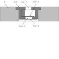
図8と図9を用いて具体的に説明する。オフキャリッジインクタンク6は連結用シール部材63を具備している。プリンタ本体の連結機構71にはニードル72が設けられている。オフキャリッジインクタンク6がプリンタ本体に装着されると、インクはニードル72から可撓性インク導管7を介してオンキャリッジインクタンク5のインク室50に流入しようとする。インク室に水頭圧制御機構51が設けられている。オフキャリッジインクタンク交換時の初期設定制御プログラムにより、プリントヘッドからインクがパージされ、プリントヘッドに連なる液室56の負圧が増大し、設計開放圧Sに達すると、水頭圧制御機構51を構成する中心的要素の弁体55がコイルスプリング53に抗して下方に引かれて図9のように開き、インクがインク室50からプリントヘッドに連なる液室56に流れ込む。これにより液室56の負圧が低下する。設計閉鎖圧に至るとコイルスプリング53により弁体55は引き戻されインクの流れ込みは停止される。以後、プリント動作により、インク吐出、負圧増大、弁開放、弁閉鎖、負圧適正化、インク吐出、これらを繰り返すのである。ここで52は弁箱、54は弁座パッキングで、共に水頭圧制御機構51の構成要素である。
This will be specifically described with reference to FIGS. The off-
オフキャリッジインクタンクからのインク送出は単に水頭圧と負圧だけで行われ、それを水頭圧制御機構51で、と言っても単なる弁機構であるが、制御しているのである。センサーもポンプも必要としない。
Ink delivery from the off-carriage ink tank is performed only by the hydraulic head pressure and the negative pressure, and this is controlled by the hydraulic head
オフキャリッジインクタンクからのインクの送出をスムーズにするためには、送出に伴う負圧がここに発生してはいけない。例えば取扱性を容易にするためハードなインク容器60を用い、その中に柔らかくインク送出にしたがって自然にしぼんで行くようなインク袋61を使う。ごく一般的なものであるが、ハードインク容器60には空気を取り入れる孔62をあけておくことが、負圧発生を防ぐために肝要である。 In order to smoothly deliver ink from the off-carriage ink tank, a negative pressure accompanying the delivery should not be generated here. For example, in order to facilitate handling, a hard ink container 60 is used, and an ink bag 61 that is soft and naturally deflates as the ink is delivered is used. Although it is very general, it is important to open the hole 62 for taking in air in the hard ink container 60 in order to prevent the generation of negative pressure.
図9は第2の解決手段のh=pのケースの説明であるが、プリントヘッドに連なる液室に許容される負圧の範囲を−(P±p)mmH2Oとすると、補充用インクタンク(オフキャリッジインクタンク)60の中心の高さ位置がHmmであるならば、そのタンクの高さ幅を最大2hmmにするだけで良い。弁体55の開閉閾値Sは、(P+H)mmH2Oになるようにコイルスプリングの力を設定することで得られる。 Although FIG. 9 is an explanation of the case of h = p of the second solving means, the range of negative pressure allowed the liquid chamber communicating with the print head - When (P ± p) mmH2O, replenishing the ink tank ( If the height position of the center of the (off-carriage ink tank) 60 is Hmm, the height width of the tank need only be 2 mm at maximum. The opening / closing threshold value S of the valve body 55 is obtained by setting the coil spring force so as to be (P + H) mmH2O.
以上が本発明の課題解決手段の基本原理であり、作用の説明であるが、これによる効果は以下のとおりである。1.補充用インクタンクをプリントヘッドよりも上方に配置する構成であり、もって広い配置スペースと拡張自由度を担保し、ただ1点上記条件:h≦pを守るだけで良いシンプルな構成が可能となった。 The above is the basic principle of the problem-solving means of the present invention and the explanation of the operation. The effects of this are as follows. 1. The replenishment ink tank is arranged above the print head, so that a wide arrangement space and expansion flexibility can be ensured, and a simple structure can be achieved by merely satisfying the above condition: h ≦ p. It was.
すなわち、インク供給のために、これまで提案されてきた他の配置や方法で必要とされているバッファー室や汲み上げポンプは不要である。これらに関わるインク移送手段、センサーや切り替え弁、フランジ等々の機械要素および制御回路も不要である。インクは単に水頭圧と負圧にしたがって流れ落ち、オンキャリッジインクタンクに流入する。シンプルで、だから低コストで必要機能を確実に実現できる。 In other words, a buffer chamber and a pumping pump that are required in other arrangements and methods that have been proposed so far are not necessary for supplying ink. Mechanical elements such as ink transfer means, sensors, switching valves, and flanges and control circuits related to these are also unnecessary. The ink simply flows down according to the water head pressure and negative pressure and flows into the on-carriage ink tank. It is simple, so it can reliably achieve the required functions at low cost.
2.補充用インクタンクを置く高さは自由である。単純にS=(P+H)mmH2O(p=hの場合)の弁を用いればよいだけのことである。 2. The height for placing the refill ink tank is arbitrary. It is only necessary to use a valve of S = (P + H) mmH2O (when p = h).
3.本発明の目的は、記録装置の大きさを大きくしないことでもある。前述のように代表的な、20年に亘り変化なく使われてきたオンキャリッジインクタンクの高さは、少しでも多くのインクを搭載したい、しかしインクのボタ落ちは避けねばならない、という2律背反性から略40mmないし50mmの高さであり続けている。そして水頭圧を制御する簡単ではあるが何らかの臓物が入っている。本発明によれば、プリントヘッドと一体と成るオンキャリッジインクタンクは、ここにインクを貯め込む目的では無いのでそれらよりは小さくて済む。その高さは、内包する弁機構ないしは類似の水頭圧制御機構の種類にもよるが、10mmないし20mmの高さで充分である。仮に20mmとしても、従来機に比し、上空に20mmないし30mmのスペースが空くのである。ここに補充用インクタンクを装填すればよいのである。上記の例では最大の高さ幅で20mmである。30mmのスペースに十分に入れ込むことができるのである。以上は、先に図5〜9を用いて説明したことを、数字を使って詳述したものである。 3. An object of the present invention is also not to increase the size of the recording apparatus. As mentioned above, the height of a typical on-carriage ink tank that has been used unchanged for 20 years is a trade-off that you want to load as much ink as possible, but you must avoid dropping ink. Due to its nature, it continues to be approximately 40 mm to 50 mm in height. And there is some simple organs to control the water head pressure. According to the present invention, the on-carriage ink tank integrated with the print head is not intended to store ink here, so it can be smaller. The height is 10 mm to 20 mm, although it depends on the type of valve mechanism or similar head pressure control mechanism to be included. Even if it is 20 mm, a space of 20 mm to 30 mm is vacated in the sky as compared with the conventional machine. A replenishment ink tank may be loaded here. In the above example, the maximum height width is 20 mm. It can be fully inserted into a 30 mm space. The above is a detailed description of what has been described above with reference to FIGS.
4.記録装置の横幅が小さく出来る。作用説明の項での説明の繰り返しではあるが、前項で「オンキャリッジインクタンクは、ここにインクを貯め込む目的では無いので小さくて済む」と記したが、これは高さだけでは無い。横幅も小さく出来る。例えば数mmに、とにかく1cm以内に、である。この数字は例示であるが、インクの色数が増えれば増えるほど、記録装置本体幅には2倍で効いてくるのであるから、効果は大きいことが理解できるはずである。 4). The width of the recording apparatus can be reduced. Although it is a repetition of the description in the section on operation, it was described in the previous section that “the on-carriage ink tank is small because it is not intended to store ink here”, but this is not only the height. The width can be reduced. For example, within a few mm, and within 1 cm anyway. This number is merely an example, but it should be understood that the greater the number of ink colors, the greater the effect because the effect on the recording apparatus main body width is doubled.
5.課題解決手段3の作用と効果を述べる。前述のように図5と図6の一点鎖線で囲まれた空間12に、課題解決手段1および2の条件を満たすことを大前提として、補充用インクタンクを配置することが出来る。この空間は本体のユーザーと対面するフロント側上部位置であり、そこに、補充用インクタンクを横一線にズラリと並べ置くことができる。ユーザーには極めて交換し易い。図3斜視図で示した従来機では、上蓋を開け、複合機であれば上部のスキャナーごと持ち上げるのであるが、それから覗き込むようにしてインクタンクを交換している。一方図7の本発明の配置では、前面のカバーを開け、必要なインクタンクを交換する。両者の扱い容易性は一目瞭然である。なお図7にも従来機のサイズを点線10で示した。製品のサイズは他にも制約条件があり設計マターではあるが、小さく出来る自由度を担保出来ることは大きな効用である。
5. The operation and effect of the problem solving means 3 will be described. As described above, the ink tank for replenishment can be arranged in the space 12 surrounded by the one-dot chain line in FIGS. 5 and 6 on the premise that the conditions of the problem solving means 1 and 2 are satisfied. This space is an upper position on the front side facing the user of the main body, and refilling ink tanks can be arranged in a line in a horizontal line there. It is very easy for the user to exchange. In the conventional machine shown in the perspective view of FIG. 3, the upper lid is opened, and in the case of a multifunction machine, the upper scanner is lifted together, but the ink tank is exchanged so as to look into it. On the other hand, in the arrangement of the present invention shown in FIG. 7, the front cover is opened and the necessary ink tank is replaced. The ease of handling of both is obvious. In FIG. 7, the size of the conventional machine is indicated by a dotted
補充用インクタンクの大きさを、数字を用いて例示する。例えば、高さ22mm(内側20mm)、横幅40mm(内側38mm)、奥行き80mm(内側70mm)とすると、内容量は53.2ccとなる。前記のように印刷1枚のインク消費量を0.05ccとすると、1,064枚となる。従来機の3倍近い印刷可能枚数である。ここで文字用の黒と、写真用の黒と、イエロー、マゼンダ、シアン、フォトマゼンダ、フォトシアンと都合7色の例で計算してみる。文字用の黒を大型にし、例えば横幅60mmとする。合計の横幅は、60+40x6=300mmである。これは、紙幅+オンキャリッジインクタンク幅x2に近似し、越えるものではない。同じ7色搭載の従来機より少なくとも5cm以上幅狭の製品が作れるのである。 The size of the ink tank for replenishment is illustrated using numbers. For example, if the height is 22 mm (inner side 20 mm), the lateral width is 40 mm (inner side 38 mm), and the depth is 80 mm (inner side 70 mm), the internal capacity is 53.2 cc. As described above, assuming that the ink consumption of one printed sheet is 0.05 cc, the number of printed sheets is 1,064. The number of printable sheets is nearly three times that of conventional machines. Here, calculation is made with an example of black for text, black for photography, yellow, magenta, cyan, photomagenta, and photocyan for convenience. The black for characters is made large, for example, the width is 60 mm. The total lateral width is 60 + 40 × 6 = 300 mm. This approximates and does not exceed the paper width + on-carriage ink tank width x2. A product that is at least 5 cm narrower than a conventional machine with the same seven colors can be made.
ビジネスユース機などで、さらにインク容量を増やしたければ、インクタンクの奥行きや幅を伸ばせばよい。具体的な構成を実施例で後述する。またインクの色数をさらに増やしたければ、その横幅を少し狭め奥行きを伸ばせばよい。このように設計の自由度が極めて高くなる。ただし、インクタンクの内側高さは20mm堅持が必須であり、これさえ守ればよいのである。(負圧変動許容幅が20mmの場合) If you want to increase the ink capacity on a business-use machine, you can increase the depth and width of the ink tank. A specific configuration will be described later in Examples. To further increase the number of ink colors, the lateral width may be slightly narrowed to increase the depth. In this way, the degree of freedom in design becomes extremely high. However, it is essential that the inner height of the ink tank is 20 mm, and it is only necessary to keep this. (When negative pressure fluctuation tolerance is 20mm)
その他の課題解決手段の作用と効果を述べる。水頭圧制御機構上部に、混入気泡の過剰な正圧開放機構を設けるものである。図10と図11にそれを番号59で示した。インク室50に何らかの理由(溶融気体、インクタンク交換時の混入気体等)で気泡が混在すると、液温が上昇した時などに膨張し、意図せずバネ力に抗して弁を押し下げ、インクを液室に押し込んでしまう。その結果液室の負圧が減少しプリントヘッド4からのインクボタ落ちを惹起する。気泡を図8および図9に番号58で例示的に示した。このような不都合を防ぐために「気体の放出、あるいは過剰な正圧の放出」が必要であり、インクジェットプリンタでは、基本的には全てのオンキャリッジインクタンクにその機構が組み込まれている。本案の構成においても、上述の水頭圧制御の基本構造と組み合わせて必要な機構であり、この組み込みによってプリントヘッドからの不如意なボタ落ちを防ぐことが出来る。
The actions and effects of other problem solving means will be described. An excessive positive pressure releasing mechanism for mixed bubbles is provided at the upper part of the water head pressure control mechanism. This is indicated by 59 in FIGS. If air bubbles are mixed in the
さらに、オンキャリッジインクタンクはプリント動作により激しく往復運動を繰り返し、その内部のインクは常に擾乱状態にある。個のインク状態が直接プリントヘッドに伝わると安定した吐出が出来なくなってしまう。そこで図8、図9の番号57のような、プリントヘッドを保護するようにインクの乱れる動きを緩和させる緩衝機構を設ける。これは連通多孔質材、例えばスポンジや繊維の詰め物などを用いる。 Furthermore, the on-carriage ink tank repeatedly reciprocates violently by the printing operation, and the ink inside thereof is always in a disturbed state. If the individual ink state is directly transmitted to the print head, stable ejection cannot be performed. Therefore, a buffering mechanism for relaxing the turbulent movement of the ink is provided so as to protect the print head as indicated by numeral 57 in FIGS. This uses a continuous porous material, such as a sponge or fiber stuffing.
これまでの説明に用いた図5、図6の記録装置の基本構成と、図8、図9の水頭圧制御機構51が本発明の典型的な形態である。具体的な構成を、黒、イエロー、マゼンダ、シアン、オレンジ、グリーンの6色を用いたコンシューマープロダクトジャンルのフォトプリンタで示す。オンキャリッジインクタンクの各色の内側寸法は0.9cmとした。それらの隔壁は0.1cm(これらのインクタンクは取り外して交換するものではないので、厚さや間隙などは不要である)、最外壁は0.2cm、合計幅は、0.9x6+0.1x5+0.2x2=6.3cmである。これを幅7cmのキャリッジに搭載した。本体幅は、紙幅21cmであるから、これに7x2cm+α(ギヤ等のメカニカル部品や外装の厚さや間隙などで略4cm)を加えて39cmとなった。従来機のオンキャリッジインクタンク搭載のキャリッジ幅は10cm近くかそれ以上であり、したがって本体幅は40cmを優に超えている。
The basic configuration of the recording apparatus shown in FIGS. 5 and 6 and the hydraulic head
奥行きは内寸法で5.0cmであり特別短くはしていない。この場所の奥行き方向には十分な余裕があるからである。高さは外寸法2.0cm、内寸法1.6cmとした。単純計算では容量は約7ccであるが、インク擾乱緩衝部材と弁機構を設けているので、自由インク液量(緩衝部材に含まれる液量を除いた液量)は略3ccである。これは連続印刷で約100枚の印刷が可能な液量である。ここでは標準原稿1枚の印刷に0.03cc使うとした。実際にはプリントヘッドの清掃目的の空吐出や吸引清掃などを行うので0.05ccで換算計算しているが、連続印刷ならこのくらいは印刷できる、余裕がある量である、と言う意味である。弁の開放遅延は小さいのでこのくらいの少量でも全く問題は無い。 The depth is 5.0 cm in internal dimensions and is not shortened. This is because there is a sufficient margin in the depth direction of this place. The height was set to an outer dimension of 2.0 cm and an inner dimension of 1.6 cm. In the simple calculation, the capacity is about 7 cc. However, since the ink disturbance buffer member and the valve mechanism are provided, the free ink liquid amount (liquid amount excluding the liquid amount contained in the buffer member) is about 3 cc. This is the amount of liquid capable of printing about 100 sheets by continuous printing. Here, 0.03 cc is used for printing one standard original. Actually, it performs conversion calculation with 0.05 cc because it performs empty discharge or suction cleaning for the purpose of cleaning the print head, but it means that it is an amount that can be printed, if there is continuous printing, this amount is enough. . Since the valve opening delay is small, there is no problem even with such a small amount.
プリントヘッドに連なる液室は負圧に保もたれていなければならない。その許容幅−(P±p)mmH2Oはプリントヘッドの孔径や形状、使用するインクの粘度等のファクターで決まる。代表的な例では、Pが25mmH2O、pが10mmH2Oと言うレベルである。−(P±p)mmH2Oはー(20±10)mmH2Oからー(30±15)mmH2Oの範囲にあることが一般的である。図5の例では、オフキャリッジインクタンクの高さ方向の中心を、プリントヘッドから5cmに設けた。ここでp=10mmH2Oなので、オフキャリッジインクタンクの高さ幅(2h)を2cm(=2p)とした。そして弁体の開放圧SがH+P、すなわち75mmH2Oとなるようにコイルスプリングの特性を設計した。 The liquid chamber connected to the print head must be kept at a negative pressure. The allowable width − (P ± p) mmH 2 O is determined by factors such as the hole diameter and shape of the print head and the viscosity of the ink used. In a typical example, P is a level of 25 mmH2O and p is 10 mmH2O. -(P ± p) mmH2O is generally in the range of-(20 ± 10) mmH2O to-(30 ± 15) mmH2O. In the example of FIG. 5, the center of the off-carriage ink tank in the height direction is provided 5 cm from the print head. Here, since p = 10 mmH 2 O, the height width (2h) of the off-carriage ink tank was set to 2 cm (= 2p). The characteristics of the coil spring were designed so that the opening pressure S of the valve body was H + P, that is, 75 mmH2O.
オフキャリッジインクタンクの大きさは、その高さ幅さえ厳守すれば、自由度高く設計できる。作用・効果の項で例示したものが典型的なタンクの一部である。再掲ではあるが、高さx横幅x奥行きが内径表示で20mmx38mmx70mmで約1,000枚の印刷用量である。より余裕のある奥行き方向を2倍の140mmにすれば2,000枚印刷可能となる。ビジネスユースのプリンタでは色数が4色で充分なことが多い。このような場合にはさらに横幅を倍増させ、4,000枚印刷が可能となる。 The size of the off-carriage ink tank can be designed with a high degree of freedom as long as the height width is strictly observed. What is exemplified in the section of action and effect is a part of a typical tank. As shown again, the height x width x depth is 20 mm x 38 mm x 70 mm in terms of inner diameter, and the printing dose is about 1,000 sheets. If the depth direction with more margins is doubled to 140 mm, 2,000 sheets can be printed. For business use printers, four colors are often sufficient. In such a case, the lateral width is further doubled, and 4,000 sheets can be printed.
1万枚印刷できるタンクも容易に設計可能である。いずれも、高さ幅2cm(内径で)さえ守れば自由自在にタンク設計ができるのである。オンキャリッジインクタンクの背丈を低く出来ることから、そこに空いたスペースが交換用インクタンクの格好の置き場所となったのである。しかも装置本体の横幅一杯に使える。奥行き方向も、存分のスペースがある。タンクの高さが好むと好まざるにかかわらず、とにかく低い。これがかえってこのような設計の自由度、あるいは拡張性をもたらしてくれる。 A tank capable of printing 10,000 sheets can be easily designed. In either case, the tank can be designed freely as long as the height is 2 cm (with an inner diameter). Since the height of the on-carriage ink tank can be lowered, the space left there becomes a suitable place for the replacement ink tank. Moreover, it can be used to the full width of the device. There is enough space in the depth direction. Regardless of whether you prefer the height of the tank, it is low anyway. This in turn brings about such design freedom or extensibility.
気体放出機構59の実施形態の拡大図を、図10と図11に示す。シンプルで確実な方法は、一方向弁と、液体は通過させないが気体は通過させるという特性を有するフィルムを張る、この2つの組み合わせの大気連通孔とすれば良い。例えばインク室5の上部に気体放出機構59を設け、これには上部開放孔59−1と下部開放孔59−2を設け、この下部開放孔59−2のインク側に多孔質の4フッ化エチレン:商品名ポアフロンの薄膜59-3を張り、シールすればよい。下部開放孔59−2の上側に、上部方向にのみ開く一方向弁59−4を設ける。インク室50の混入気体の圧力が上部開放孔の大気圧より上がると、図11のように一方向弁59−4が開き、混入気体を上部の大気中に開放する。そうでないときは、インク室50が負圧になっても、一方向弁59−4は図10のように閉じており、外部から空気を吸い込むことは無い。
An enlarged view of an embodiment of the
水頭圧制御機構51の他の実施例を図12、図13に示す。52−2は弁箱、55−1は薄いバネ板で成る弁体であり、流入口52−3を塞いでいる。弁体は開放圧がSmmH2Oに設定してある。インク吐出によって56の負圧が増大し、水頭圧とあいまってSを越えると、図13の55−1ようにこの弁体が開き流入口52−3からインクを通過させる。
Another embodiment of the hydraulic head
さらに他の水頭圧制御機構51を図14、図15に示す。52−2は弁箱、55−2は球形のボール、55−3はコイルバネである。このボールとバネで弁体が構成されている。負圧の増大にしたがって、上記の弁と同じように、図15の55−2のようにこの弁体が開き流入口52−3からインクを通過させる。
Still another hydraulic head
気体放出機構59の他の実施形態の拡大図を、図16、図17に示す。59−5は球形のボール、59−6はコイルバネである。このボールとバネで弁体が構成されている。インク室50の混入気体の圧力が上部開放孔の外の大気圧より上がると、図17の59−51のボールのように、バネ59−61を押し縮め、下部開放孔59−2から離れ、気体の放出口を開く。そして混入気体を上部の大気中に開放する。
The enlarged view of other embodiment of the gas discharge |
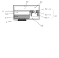
図18にビジネスユースのプリンタの構成例を示す。商品仕様によりけりではあるが、例えば10,000枚を超えるインク容量を提供しようとすることもあろう。この図のごとく容易に可能である。例えば番号6−3で示す黒用超大容量オフキャリッジインクタンクは幅20cm、奥行き20cm、高さ2cmのインクタンクとすれば、800ccであり、16,000枚のプリントが可能である。インクタンクは薄いので、2段に配置することも可能である。番号6−4で示すYMC各色のカラー用超大容量オフキャリッジインクタンクは、幅10cm、奥行き20cm、高さ2cmのインクタンクとすれば、400ccであり、各色8,000枚のプリントが可能である。 FIG. 18 shows a configuration example of a business use printer. Depending on the product specifications, the ink capacity may exceed 10,000, for example. This is easily possible as shown in this figure. For example, if the black extra-large-capacity off-carriage ink tank indicated by reference numeral 6-3 is an ink tank having a width of 20 cm, a depth of 20 cm, and a height of 2 cm, it is 800 cc and can print 16,000 sheets. Since the ink tank is thin, it can be arranged in two stages. The ultra-large capacity off-carriage ink tank for each color of YMC indicated by No. 6-4 is 400 cc if an ink tank having a width of 10 cm, a depth of 20 cm, and a height of 2 cm is capable of printing 8,000 sheets of each color. .
本発明は以上の実施形態に限定されることなく、公知のインクジェット方式記録装置に提案されている様々な要素技術が設計の目的に応じて援用することが出来、種々の実施形態で対応可能である。補充用インクタンクの高さ幅2h mmが負圧変動許容幅2p mm以内と、水頭圧制御の開閉圧SをH+P(h=pの時)とすることを前提として。 The present invention is not limited to the above-described embodiments, and various elemental technologies proposed for known ink jet recording apparatuses can be incorporated according to the purpose of design, and can be supported by various embodiments. is there. Assuming that the height width 2h mm of the replenishment ink tank is within 2p mm of the negative pressure fluctuation allowable width and that the opening / closing pressure S of the head pressure control is H + P (when h = p).
本発明をコンシューマープロダクツとしてのインクジェト方式記録装置を中心に説明し、ビジネスユースのプリンタへの適用も紹介してきた。コストをかけても良い、大判プリンタや、プロ仕様の写真用プリンタ、あるいは産業用のプリンタにも適用できる。また、さらにはポータブルプリンタですら、設計の狙いによれば使ってみることも有意な効果をもたらしてくれることもあろう。 The present invention has been mainly described with an inkjet recording apparatus as a consumer product, and has also been introduced to business use printers. It can also be applied to large format printers, professional photographic printers, or industrial printers that may be costly. And even portable printers can have a significant effect if you use them, depending on your design goals.
4 プリントヘッド
5 オンキャリッジインクタンク
6 補充用オフキャリッジインクタンク
6−3 黒用超大容量オフキャリッジインクタンク例
6−4 カラー用超大容量オフキャリッジインクタンク例
7 インク導管
8 補充用オフキャリッジインクタンク拡張用予備スペース
10 従来機外形の概念図
11 本案記録装置の外形概念図
50 インク室
51 水頭圧制御機構
52 弁箱
53 コイルスプリング
55 弁体
55−1 バネ板弁体
55−2 ボール弁体
55−3 コイルばね
56 プリントヘッドに連なる液室
57 緩衝機構
59 気体放出機構
59−3 多孔質の4フッ化エチレン薄膜
59−4 一方向弁
59−5 ボール弁体
59−6 コイルばね
63 連結用シール部材
72 ニードル
4 Print head
5 On-
8 Supplementary space for expansion of off-carriage ink tank for
Claims (1)
Priority Applications (2)
| Application Number | Priority Date | Filing Date | Title |
|---|---|---|---|
| JP2012083007A JP5994043B2 (en) | 2012-03-30 | 2012-03-30 | Inkjet recording device |
| PCT/JP2013/059547 WO2013147167A2 (en) | 2012-03-30 | 2013-03-29 | Ink-jet recording device |
Applications Claiming Priority (1)
| Application Number | Priority Date | Filing Date | Title |
|---|---|---|---|
| JP2012083007A JP5994043B2 (en) | 2012-03-30 | 2012-03-30 | Inkjet recording device |
Publications (3)
| Publication Number | Publication Date |
|---|---|
| JP2013212602A JP2013212602A (en) | 2013-10-17 |
| JP2013212602A5 JP2013212602A5 (en) | 2015-02-12 |
| JP5994043B2 true JP5994043B2 (en) | 2016-09-21 |
Family
ID=49261358
Family Applications (1)
| Application Number | Title | Priority Date | Filing Date |
|---|---|---|---|
| JP2012083007A Expired - Fee Related JP5994043B2 (en) | 2012-03-30 | 2012-03-30 | Inkjet recording device |
Country Status (2)
| Country | Link |
|---|---|
| JP (1) | JP5994043B2 (en) |
| WO (1) | WO2013147167A2 (en) |
Families Citing this family (4)
| Publication number | Priority date | Publication date | Assignee | Title |
|---|---|---|---|---|
| JP2015205437A (en) | 2014-04-18 | 2015-11-19 | 船井電機株式会社 | printer |
| JP7091753B2 (en) * | 2017-10-20 | 2022-06-28 | セイコーエプソン株式会社 | Liquid sprayer |
| US10696054B2 (en) * | 2017-10-24 | 2020-06-30 | Seiko Epson Corporation | Recording apparatus, liquid storage unit, and medium accommodation unit |
| JP7056177B2 (en) | 2017-10-24 | 2022-04-19 | セイコーエプソン株式会社 | Recording device, liquid storage unit, and medium storage unit |
Family Cites Families (2)
| Publication number | Priority date | Publication date | Assignee | Title |
|---|---|---|---|---|
| JP3991993B2 (en) * | 2001-11-12 | 2007-10-17 | セイコーエプソン株式会社 | Liquid ejector |
| JP2010052359A (en) * | 2008-08-29 | 2010-03-11 | Sii Printek Inc | Liquid jet recorder and liquid jet recording method |
-
2012
- 2012-03-30 JP JP2012083007A patent/JP5994043B2/en not_active Expired - Fee Related
-
2013
- 2013-03-29 WO PCT/JP2013/059547 patent/WO2013147167A2/en active Application Filing
Also Published As
| Publication number | Publication date |
|---|---|
| WO2013147167A2 (en) | 2013-10-03 |
| WO2013147167A3 (en) | 2013-11-28 |
| JP2013212602A (en) | 2013-10-17 |
Similar Documents
| Publication | Publication Date | Title |
|---|---|---|
| AU2003264950B2 (en) | Liquid supply system, fluid communicating structure, ink supply system, and inkjet recording head utilizing the fluid communicating structure | |
| JP6498098B2 (en) | Recording apparatus and liquid storage member | |
| JP5994043B2 (en) | Inkjet recording device | |
| JP2005219483A (en) | Device for continuously feeding ink under constant pressure | |
| JP5978400B2 (en) | Liquid supply mechanism and printing apparatus | |
| JP2005161854A (en) | Ink cartridge | |
| WO2006068313A1 (en) | Ink tank and ink jet recording apparatus | |
| JP2008296415A (en) | Fluid feeding system and fluid jet apparatus using the system | |
| US20130061982A1 (en) | Ink cartridge refilling device | |
| JP2023115276A (en) | Inkjet recording device and ink tank | |
| JP4457637B2 (en) | Head cartridge and liquid ejection device | |
| WO2013165012A1 (en) | Inkjet recording device | |
| JP6119338B2 (en) | Image recording device | |
| JP2006110959A (en) | Ink container | |
| CN109878215B (en) | Image forming agent replenishing bottle | |
| CN201633285U (en) | Ink box of ink-jet printer | |
| KR100809884B1 (en) | Ink Cartridge for Printer | |
| JP2013230651A5 (en) | ||
| CN201604359U (en) | Ink-jet printer ink box | |
| JP2010143135A (en) | Inkjet recording apparatus and inkjet recording method | |
| JP3991993B2 (en) | Liquid ejector | |
| JP2022026847A (en) | Inkjet recording device and ink tank | |
| JP6296377B2 (en) | Liquid cartridge | |
| JP6666052B2 (en) | Recording device | |
| JP2018099860A (en) | Liquid ejecting apparatus |
Legal Events
| Date | Code | Title | Description |
|---|---|---|---|
| A521 | Written amendment |
Free format text: JAPANESE INTERMEDIATE CODE: A523 Effective date: 20141012 |
|
| AA91 | Notification of revocation by ex officio |
Free format text: JAPANESE INTERMEDIATE CODE: A971091 Effective date: 20141209 |
|
| A621 | Written request for application examination |
Free format text: JAPANESE INTERMEDIATE CODE: A621 Effective date: 20141217 |
|
| A871 | Explanation of circumstances concerning accelerated examination |
Free format text: JAPANESE INTERMEDIATE CODE: A871 Effective date: 20150323 |
|
| A975 | Report on accelerated examination |
Free format text: JAPANESE INTERMEDIATE CODE: A971005 Effective date: 20150519 |
|
| A131 | Notification of reasons for refusal |
Free format text: JAPANESE INTERMEDIATE CODE: A131 Effective date: 20150616 |
|
| A521 | Written amendment |
Free format text: JAPANESE INTERMEDIATE CODE: A523 Effective date: 20150814 |
|
| A131 | Notification of reasons for refusal |
Free format text: JAPANESE INTERMEDIATE CODE: A131 Effective date: 20151124 |
|
| A521 | Written amendment |
Free format text: JAPANESE INTERMEDIATE CODE: A523 Effective date: 20160123 |
|
| TRDD | Decision of grant or rejection written | ||
| A01 | Written decision to grant a patent or to grant a registration (utility model) |
Free format text: JAPANESE INTERMEDIATE CODE: A01 Effective date: 20160329 |
|
| A61 | First payment of annual fees (during grant procedure) |
Free format text: JAPANESE INTERMEDIATE CODE: A61 Effective date: 20160427 |
|
| R150 | Certificate of patent or registration of utility model |
Ref document number: 5994043 Country of ref document: JP Free format text: JAPANESE INTERMEDIATE CODE: R150 |
|
| LAPS | Cancellation because of no payment of annual fees |