JP5993312B2 - Pressure measuring instrument and substrate processing apparatus including the pressure measuring instrument - Google Patents
Pressure measuring instrument and substrate processing apparatus including the pressure measuring instrument Download PDFInfo
- Publication number
- JP5993312B2 JP5993312B2 JP2013005777A JP2013005777A JP5993312B2 JP 5993312 B2 JP5993312 B2 JP 5993312B2 JP 2013005777 A JP2013005777 A JP 2013005777A JP 2013005777 A JP2013005777 A JP 2013005777A JP 5993312 B2 JP5993312 B2 JP 5993312B2
- Authority
- JP
- Japan
- Prior art keywords
- diaphragm
- pressure measuring
- pressure
- measuring device
- pressure chamber
- Prior art date
- Legal status (The legal status is an assumption and is not a legal conclusion. Google has not performed a legal analysis and makes no representation as to the accuracy of the status listed.)
- Active
Links
- 239000000758 substrate Substances 0.000 title claims description 71
- 238000012545 processing Methods 0.000 title claims description 68
- 238000005259 measurement Methods 0.000 claims description 30
- 238000004891 communication Methods 0.000 claims description 19
- 238000001514 detection method Methods 0.000 claims description 19
- 230000008859 change Effects 0.000 claims description 18
- 238000006073 displacement reaction Methods 0.000 claims description 16
- 230000003287 optical effect Effects 0.000 claims description 3
- 239000007789 gas Substances 0.000 description 72
- 239000007787 solid Substances 0.000 description 33
- 238000000034 method Methods 0.000 description 21
- 230000000052 comparative effect Effects 0.000 description 19
- 238000006243 chemical reaction Methods 0.000 description 17
- 239000007795 chemical reaction product Substances 0.000 description 12
- 239000002244 precipitate Substances 0.000 description 8
- 238000000231 atomic layer deposition Methods 0.000 description 7
- 239000010408 film Substances 0.000 description 7
- 230000008569 process Effects 0.000 description 7
- 239000002245 particle Substances 0.000 description 6
- 238000002474 experimental method Methods 0.000 description 5
- 238000010926 purge Methods 0.000 description 5
- 239000012495 reaction gas Substances 0.000 description 4
- 230000007423 decrease Effects 0.000 description 3
- 238000000151 deposition Methods 0.000 description 3
- 230000000694 effects Effects 0.000 description 3
- 238000010438 heat treatment Methods 0.000 description 3
- 239000002052 molecular layer Substances 0.000 description 3
- IJGRMHOSHXDMSA-UHFFFAOYSA-N Atomic nitrogen Chemical compound N#N IJGRMHOSHXDMSA-UHFFFAOYSA-N 0.000 description 2
- 230000008901 benefit Effects 0.000 description 2
- 238000009530 blood pressure measurement Methods 0.000 description 2
- 230000008021 deposition Effects 0.000 description 2
- 238000010586 diagram Methods 0.000 description 2
- 239000012530 fluid Substances 0.000 description 2
- 239000000463 material Substances 0.000 description 2
- 238000012986 modification Methods 0.000 description 2
- 230000004048 modification Effects 0.000 description 2
- 239000000047 product Substances 0.000 description 2
- CBENFWSGALASAD-UHFFFAOYSA-N Ozone Chemical compound [O-][O+]=O CBENFWSGALASAD-UHFFFAOYSA-N 0.000 description 1
- XUIMIQQOPSSXEZ-UHFFFAOYSA-N Silicon Chemical compound [Si] XUIMIQQOPSSXEZ-UHFFFAOYSA-N 0.000 description 1
- 230000015572 biosynthetic process Effects 0.000 description 1
- 239000000919 ceramic Substances 0.000 description 1
- 230000008602 contraction Effects 0.000 description 1
- 239000011261 inert gas Substances 0.000 description 1
- 229910052757 nitrogen Inorganic materials 0.000 description 1
- 239000010453 quartz Substances 0.000 description 1
- 239000000376 reactant Substances 0.000 description 1
- 229910052594 sapphire Inorganic materials 0.000 description 1
- 239000010980 sapphire Substances 0.000 description 1
- VSZWPYCFIRKVQL-UHFFFAOYSA-N selanylidenegallium;selenium Chemical compound [Se].[Se]=[Ga].[Se]=[Ga] VSZWPYCFIRKVQL-UHFFFAOYSA-N 0.000 description 1
- 229910052710 silicon Inorganic materials 0.000 description 1
- 239000010703 silicon Substances 0.000 description 1
- VYPSYNLAJGMNEJ-UHFFFAOYSA-N silicon dioxide Inorganic materials O=[Si]=O VYPSYNLAJGMNEJ-UHFFFAOYSA-N 0.000 description 1
- 239000010409 thin film Substances 0.000 description 1
- 238000012546 transfer Methods 0.000 description 1
- 230000009466 transformation Effects 0.000 description 1
Images


Classifications
-
- G—PHYSICS
- G01—MEASURING; TESTING
- G01L—MEASURING FORCE, STRESS, TORQUE, WORK, MECHANICAL POWER, MECHANICAL EFFICIENCY, OR FLUID PRESSURE
- G01L19/00—Details of, or accessories for, apparatus for measuring steady or quasi-steady pressure of a fluent medium insofar as such details or accessories are not special to particular types of pressure gauges
- G01L19/14—Housings
- G01L19/145—Housings with stress relieving means
-
- G—PHYSICS
- G01—MEASURING; TESTING
- G01L—MEASURING FORCE, STRESS, TORQUE, WORK, MECHANICAL POWER, MECHANICAL EFFICIENCY, OR FLUID PRESSURE
- G01L19/00—Details of, or accessories for, apparatus for measuring steady or quasi-steady pressure of a fluent medium insofar as such details or accessories are not special to particular types of pressure gauges
- G01L19/06—Means for preventing overload or deleterious influence of the measured medium on the measuring device or vice versa
- G01L19/0627—Protection against aggressive medium in general
- G01L19/0636—Protection against aggressive medium in general using particle filters
-
- G—PHYSICS
- G01—MEASURING; TESTING
- G01L—MEASURING FORCE, STRESS, TORQUE, WORK, MECHANICAL POWER, MECHANICAL EFFICIENCY, OR FLUID PRESSURE
- G01L9/00—Measuring steady of quasi-steady pressure of fluid or fluent solid material by electric or magnetic pressure-sensitive elements; Transmitting or indicating the displacement of mechanical pressure-sensitive elements, used to measure the steady or quasi-steady pressure of a fluid or fluent solid material, by electric or magnetic means
- G01L9/0041—Transmitting or indicating the displacement of flexible diaphragms
- G01L9/0042—Constructional details associated with semiconductive diaphragm sensors, e.g. etching, or constructional details of non-semiconductive diaphragms
Landscapes
- Physics & Mathematics (AREA)
- General Physics & Mathematics (AREA)
- Health & Medical Sciences (AREA)
- Child & Adolescent Psychology (AREA)
- Chemical & Material Sciences (AREA)
- Analytical Chemistry (AREA)
- Measuring Fluid Pressure (AREA)
- Engineering & Computer Science (AREA)
- Condensed Matter Physics & Semiconductors (AREA)
- Manufacturing & Machinery (AREA)
- Computer Hardware Design (AREA)
- Microelectronics & Electronic Packaging (AREA)
- Power Engineering (AREA)
Description
本発明は、圧力測定器、又は、その圧力測定器を備える基板処理装置に関する。 The present invention relates to a pressure measuring device or a substrate processing apparatus including the pressure measuring device.
基準圧力室と測定圧力室との境界にダイヤフラム(例えば隔膜式センサ)を配置し、基準圧力室と測定圧力室との圧力差で変形したダイヤフラムの変形量に基づいて、測定圧力室の圧力を測定する圧力測定器(所謂、ダイヤフラム式測定器)が知られている。圧力測定器のダイヤフラムには、変形可能な弾性体(例えば薄膜など)が用いられる。圧力測定器では、ダイヤフラムにパーティクル、反応生成物等が付着すると、付着したパーティクル等によってダイヤフラムに応力が作用し(例えば図1のf1又はf2)、ダイヤフラム(図1のTd)の変形量(撓み量)に影響を与える。 A diaphragm (for example, a diaphragm type sensor) is arranged at the boundary between the reference pressure chamber and the measurement pressure chamber, and the pressure in the measurement pressure chamber is adjusted based on the deformation amount of the diaphragm deformed due to the pressure difference between the reference pressure chamber and the measurement pressure chamber. A pressure measuring device (so-called diaphragm type measuring device) for measuring is known. A deformable elastic body (for example, a thin film) is used for the diaphragm of the pressure measuring device. In the pressure measuring device, when particles, reaction products, or the like adhere to the diaphragm, stress is applied to the diaphragm by the adhered particles or the like (for example, f1 or f2 in FIG. 1), and the deformation amount (deflection) of the diaphragm (Td in FIG. 1). Quantity).
特許文献1では、ダイヤフラムの表面に複数のT字状の突起物を形成して、T字状の突起物で気体中のパーティクル等を捕捉する技術を開示している。 Patent Document 1 discloses a technique in which a plurality of T-shaped protrusions are formed on the surface of a diaphragm and particles or the like in the gas are captured by the T-shaped protrusions.
しかしながら、特許文献1に開示されている技術では、ダイヤフラムに付着するパーティクル等を低減することができるが、複数のT字状の突起物を形成するため、ダイヤフラムの表面の構造が複雑となる。また、特許文献1に開示されている技術では、気体中に含まれる固体(パーティクルなど)をダイヤフラムの表面に形成したT字状の突起物で捕捉することができるが、ダイヤフラムの表面で析出される析出物(付着物)を捕捉することができない場合がある。 However, with the technique disclosed in Patent Document 1, particles and the like attached to the diaphragm can be reduced, but a plurality of T-shaped protrusions are formed, so that the structure of the surface of the diaphragm becomes complicated. In the technique disclosed in Patent Document 1, solids (particles, etc.) contained in a gas can be captured by a T-shaped projection formed on the surface of the diaphragm, but are deposited on the surface of the diaphragm. In some cases, deposits (attachments) cannot be captured.
例えば原子層成膜(ALD)法(又は、分子層成膜(MLD)法)を用いて基板処理する場合で、圧力測定器を用いて処理室内の圧力を測定するためには、互いに反応する2種類のガスを交互に供給したときの処理室内の圧力をそれぞれ測定する必要がある。この場合、互いに反応する2種類のガスが交互にダイヤフラム表面と接触するため、ダイヤフラム表面に2種類のガスの反応物(析出物)が生成される(析出する)場合がある。すなわち、特許文献1に開示されている技術では、ダイヤフラムの表面で析出する析出物をその表面に形成したT字状の突起物で捕捉することができない場合がある。また、特許文献1に開示されている技術では、析出物によって作用する応力によって、基準圧力室と測定圧力室との圧力差によるダイヤフラムの変形を正しく測定することができない場合がある。 For example, when a substrate is processed using an atomic layer deposition (ALD) method (or a molecular layer deposition (MLD) method), in order to measure the pressure in the processing chamber using a pressure measuring device, they react with each other. It is necessary to measure the pressure in the processing chamber when two kinds of gases are alternately supplied. In this case, since two kinds of gases that react with each other alternately come into contact with the diaphragm surface, reactants (precipitates) of the two kinds of gases may be generated (deposited) on the diaphragm surface. That is, in the technique disclosed in Patent Document 1, there is a case where the precipitate deposited on the surface of the diaphragm cannot be captured by the T-shaped projection formed on the surface. Further, in the technique disclosed in Patent Document 1, there is a case where the deformation of the diaphragm due to the pressure difference between the reference pressure chamber and the measurement pressure chamber cannot be correctly measured due to the stress acting on the precipitate.
本発明は、上記の事情に鑑み、ダイヤフラムに固体が付着した場合でも、付着した固体によって作用する応力がダイヤフラムの変形に与える影響を軽減することができる圧力測定器を提供することを目的とする。 In view of the above circumstances, an object of the present invention is to provide a pressure measuring instrument that can reduce the influence of stress acting on the diaphragm on the deformation of the diaphragm even when the solid adheres to the diaphragm. .
本発明の一の態様によれば、基準圧力室と測定圧力室との境界に配置されたダイヤフラムを用いて、前記ダイヤフラムの変形を検出することによって、該測定圧力室の圧力を測定する圧力測定器であって、前記基準圧力室を内部に備える検出部と、前記ダイヤフラムと前記測定圧力室とを連通する連通部と、前記検出部と前記連通部との間に配置され、略円環形状の通路を形成する円環流路形成部とを有し、前記検出部は、円筒形状であり、該円筒形状の内部に前記ダイヤフラムを配置され、前記連通部は、前記検出部の該円筒形状の内径より小さい内径を有する円管形状であり、前記測定圧力室の気体を前記略円環形状の通路に流入させ、前記円環流路形成部は、前記連通部から流入する気体を前記略円環形状の通路に通過させ、通過させた気体を前記ダイヤフラムの側面に供給し、前記略円環形状の通路は、前記ダイヤフラムの単位面積当たりの変位量の微分値が最大値となる位置と対向する位置に形成される、ことを特徴とする圧力測定器が提供される。また、前記略円環形状の通路の内径と外径との範囲は、前記基準圧力室と前記測定圧力室との圧力差によって前記ダイヤフラムが軸対称で変形する位置に対向する所定の範囲である、ことを特徴とする、圧力測定器であってもよい。また、前記円環流路形成部は、円形平板を備え、前記円形平板の外径は、前記検出部の内径又は前記ダイヤフラムの外径に対して10%から30%の範囲内の大きさである、ことを特徴とする、圧力測定器であってもよい。また、前記円形平板の外径は、前記検出部の内径又は前記ダイヤフラムの外径に基づいて設定されることによって、前記圧力測定器の使用時間に対する0点位置の変化量及び/又は0点位置の変化する方向を制御する、ことを特徴とする、圧力測定器であってもよい。更に、前記ダイヤフラムの変形を静電容量式、圧電式、又は、光学式で検出する、ことを特徴とする、圧力測定器であってもよい。
According to one aspect of the present invention, a pressure measurement that measures the pressure of the measurement pressure chamber by detecting deformation of the diaphragm using a diaphragm disposed at the boundary between the reference pressure chamber and the measurement pressure chamber. A detector that includes the reference pressure chamber therein, a communication portion that communicates the diaphragm and the measurement pressure chamber, and a substantially annular shape that is disposed between the detection portion and the communication portion. An annular flow path forming part that forms a passage of the sensor, wherein the detection part has a cylindrical shape, the diaphragm is disposed inside the cylindrical shape, and the communication part has a cylindrical shape of the detection part. An annular tube having an inner diameter smaller than an inner diameter, and the gas in the measurement pressure chamber is caused to flow into the substantially annular passage, and the annular flow path forming portion causes the gas flowing in from the communication portion to flow into the substantially annular ring. Let it pass through the shaped passage The gas is supplied to the side surface of the diaphragm, the passage of the substantially circular ring shape, the differential value of the displacement amount per unit area of the diaphragm is formed at a position located opposed to the maximum value, and characterized in that A pressure gauge is provided. The range between the inner diameter and the outer diameter of the substantially annular passage is a predetermined range facing a position where the diaphragm is deformed in an axial symmetry due to a pressure difference between the reference pressure chamber and the measurement pressure chamber. A pressure measuring device may be used. The annular flow path forming portion includes a circular flat plate, and the outer diameter of the circular flat plate is in a range of 10% to 30% with respect to the inner diameter of the detection portion or the outer diameter of the diaphragm. A pressure measuring device may be used. Further, the outer diameter of the circular flat plate is set based on the inner diameter of the detection unit or the outer diameter of the diaphragm, so that the change amount of the zero point position and / or the zero point position with respect to the usage time of the pressure measuring device is set. The pressure measuring device may be characterized by controlling the direction in which the pressure changes . Furthermore, the pressure measuring device may be characterized in that the deformation of the diaphragm is detected by a capacitance type, a piezoelectric type, or an optical type.
本発明の他の態様によれば、上記のいずれか一つの圧力測定器と、前記測定圧力室と連通する処理室で基板を処理する基板処理手段と、を有する基板処理装置が提供される。 According to another aspect of the present invention, there is provided a substrate processing apparatus including any one of the pressure measuring devices described above and a substrate processing means for processing a substrate in a processing chamber communicating with the measurement pressure chamber.
本発明に係る圧力測定器又は基板処理装置によれば、ダイヤフラムに固体が付着した場合でも、付着した固体によって作用する応力がダイヤフラムの変形に与える影響を軽減することができる。 According to the pressure measuring instrument or the substrate processing apparatus of the present invention, even when a solid adheres to the diaphragm, it is possible to reduce the influence of the stress acting on the attached solid on the deformation of the diaphragm.
添付の図面を参照しながら、限定的でない例示の実施形態に係る圧力測定器を用いて、本発明を説明する。本発明は、以下に説明する圧力測定器以外でも、ダイヤフラム(例えば隔膜)を用いて、ダイヤフラムの変形量に基づいて圧力を測定するもの(装置、機器、ユニット、システムなど)であれば、いずれのものにも用いることができる。 The present invention will be described using a pressure measuring device according to a non-limiting exemplary embodiment with reference to the accompanying drawings. The present invention is not limited to the pressure measuring device described below, and any device that measures the pressure based on the amount of deformation of the diaphragm (for example, a diaphragm) (apparatus, device, unit, system, etc.) Can also be used.
なお、以後の説明において、添付の全図面の記載の同一又は対応する装置、部品又は部材には、同一又は対応する参照符号を付し、重複する説明を省略する。また、図面は、特に説明しない限り、装置、部品若しくは部材間の限定的な関係を示すことを目的としない。したがって、具体的な相関関係は、以下の限定的でない実施形態に照らし、当業者により決定することができる。 In the following description, the same or corresponding devices, parts, or members described in all the attached drawings are denoted by the same or corresponding reference numerals, and redundant description is omitted. Also, the drawings are not intended to show a limited relationship between devices, parts or members unless specifically described. Accordingly, specific correlations can be determined by one skilled in the art in light of the following non-limiting embodiments.
第1の実施形態に係る圧力測定器100又は第2の実施形態に係る基板処理装置200を用いて、本発明を説明する。
The present invention will be described using the
[第1の実施形態]
[圧力測定器の構成]
図2を用いて、本発明の第1の実施形態に係る圧力測定器100について説明する。なお、図2は、本実施形態に係る圧力測定器100の一例を説明する概略断面図である。
[First Embodiment]
[Configuration of pressure measuring instrument]
The pressure measuring
図2に示すように、本実施形態に係る圧力測定器100は、所謂ダイヤフラム式測定器である。すなわち、圧力測定器100は、基準圧力室10Aの内圧と測定圧力室10Bの内圧との圧力差に基づいて、測定圧力室10Bの圧力を測定(検出)する。また、圧力測定器100は、基準圧力室10Aと測定圧力室10Bとの境界に配置されたダイヤフラム10の変形量に基づいて、基準圧力室10Aの内圧と測定圧力室10Bの内圧との圧力差を検出する。
As shown in FIG. 2, the
ここで、基準圧力室10Aとは、圧力測定器100の外部から隔離された密閉空間である。基準圧力室10Aは、例えば高い真空度を有する空間であってもよい。測定圧力室10Bとは、圧力を測定する空間と連通する空間である。すなわち、測定圧力室10Bは、圧力を測定する空間の圧力変動に追従して、その内圧を変化させる。圧力測定器100は、圧力を測定する空間から気体を流入された測定圧力室10Bの圧力(内圧)を測定することによって、圧力を測定する空間の圧力を検出する。
Here, the reference pressure chamber 10 </ b> A is a sealed space isolated from the outside of the
圧力測定器100は、基準圧力室10Aを内部に備える検出部21と、ダイヤフラム10と測定圧力室10Bとを連通する連通部22と、検出部21と連通部22との間に配置された円環流路形成部23とを有する。
The
ダイヤフラム10は、基準圧力室10Aと測定圧力室10Bとの圧力差によって変形するもの(隔膜など)である。ダイヤフラム10は、本実施形態では、図2に示すように、検出部21の内部に配置(固定)される。ダイヤフラム10は、例えばステンレスダイヤフラム、シリコンダイヤフラム、セラミックダイヤフラム又はサファイアダイヤフラムなどを用いることができる。また、ダイヤフラム10の変形を測定する方法は、静電容量式(キャパシタンス式)、圧電式、光学式又はその他変形を検出できる方法を用いることができる。
The diaphragm 10 is deformed by a pressure difference between the
検出部21は、基準圧力室10Aを形成する部材である。検出部21は、本実施形態では、円筒形状を有する。また、検出部21は、円筒形状の内部にダイヤフラム10を配置(固定)している。
The
連通部22は、ダイヤフラム10の側面と測定圧力室10Bとを連通する部材である。連通部22は、本実施形態では、円管形状を有する。連通部22の円管形状の一方の開口は、圧力(内圧)を測定する空間(例えば図4の基板処理装置200の反応管212(処理室))と連通している。連通部22の円管形状の他方の開口は、円環流路形成部23と接続されている。
The
円環流路形成部23は、検出部21と連通部22との間に略円環形状の通路を形成する部材である。円環流路形成部23は、その中央部に略円形の開口23Paを有する。また、円環流路形成部23は、その開口23Paに後述する円形平板23Pを固定する。
The annular flow
円形平板23Pは、連通部22から流入する気体(流体)の流れを阻害(邪魔)する部材である。円形平板23Pは、例えば邪魔板、バッファ板などを用いることができる。円形平板23Pの外径は、開口23Paの径より小さい。すなわち、円形平板23Pは、開口23Paに固定されることによって、開口23Paに略円環形状の通路を形成する。なお、円形平板23Pの仕様は、後述する[圧力測定器の内部流路]で説明する。
The circular
[圧力測定器の内部流路]
以下に、本発明の実施形態に係る圧力測定器100の内部流路について説明する。
[Internal flow path of pressure measuring instrument]
Below, the internal flow path of the
図1は、ダイヤフラムに作用する応力を説明する説明図である。 FIG. 1 is an explanatory diagram for explaining the stress acting on the diaphragm.
図1に示すように、圧力測定器のダイヤフラムTdは、ダイヤフラムTdの一方の側面と他方の側面との圧力差によって撓む。すなわち、ダイヤフラムTdは、その中心を軸対称に変形する。ダイヤフラムTdは、例えば基準圧力室10Aの内圧より測定圧力室10Bの圧力が高い場合に、その中心部が上方(図中の−y方向)に移動(変形)する。
As shown in FIG. 1, the diaphragm Td of the pressure measuring device is bent by a pressure difference between one side surface and the other side surface of the diaphragm Td. That is, the diaphragm Td deforms its center symmetrically. For example, when the pressure in the
また、ダイヤフラムTdでは、測定圧力室10Bに流入した気体に固体(パーティクルなど)が含まれる場合で、その固体がダイヤフラムTdの表面に付着したときに、その付着した固体によってダイヤフラムTdの表面に応力が発生する。ダイヤフラムTdでは、例えば付着した固体が膜を形成し、その膜が収縮すると、ダイヤフラムTdの表面に収縮応力が発生する。このとき、発生した応力は、ダイヤフラムTdの変形に基づく圧力測定時において、圧力を過大に測定させるプラスシフト応力(図中のf1)、又は、圧力を過小に測定させるマイナスシフト応力(図中のf2)となる。このように、圧力測定器は、ダイヤフラムTdの表面に固体が付着すると、圧力差に基づくダイヤフラムTdの変形に誤差が含まれ、圧力を測定する精度が低下する。
In the case of the diaphragm Td, when the gas flowing into the
図3は、本実施形態に係る圧力測定器100のダイヤフラム10の変形を説明する説明図である。ここで、図3の横軸は、ダイヤフラム10の中心位置を原点としたときのダイヤフラム10の中心位置からの距離(図1のx軸方向の位置)を示す。図3の点線Ldhは、ダイヤフラム10の中心位置から離間する位置における変位量H(図1のy軸方向の変位)を示し、左縦軸に対応する。図3の実線Lhは、ダイヤフラム10の単位面積当たりの変化量dH(単位面積当たりの変位量の微分値)を示し、右縦軸に対応する。
FIG. 3 is an explanatory diagram for explaining a modification of the diaphragm 10 of the
図3に示すように、本実施形態に係る圧力測定器100のダイヤフラム10は、ダイヤフラム10の外縁の位置を基準として、その外縁から中心に向かって変位量Hを増加させる。また、圧力測定器100は、ダイヤフラム10の中心から所定の距離を離間した位置において、変化量dH(変位量Hの微分値)が最大値となる。ここで、ダイヤフラム10の変化量dHが最大値となる位置は、ダイヤフラム10の形状及び材質等によって変化する。圧力測定器100は、ダイヤフラム10の半径に対して例えば10%から20%の距離を外縁に向かった位置で変化量dHが最大となってもよいし、例えば5%から15%の距離を外縁に向かった位置で変化量dHが最大値となってもよい。なお、圧力測定器100のダイヤフラム10は、その中心付近では変化量dHが急激に減少し、その外縁に向かって変化量dHが緩やかに減少する。
As shown in FIG. 3, the diaphragm 10 of the
ダイヤフラム10の変化量dHはダイヤフラム10の撓み量であるが、撓み量の大きい箇所に上記の固体を付着(又は成膜)されても、付着(又は成膜)によって発生する応力は撓み量と比較して相対的に小さい。一方、ダイヤフラム10の撓み量が小さい箇所に上記の固体を付着(又は成膜)された場合では、付着(又は成膜)によって発生する応力が撓み量と比較して相対的に大きくなる。すなわち、圧力測定器100は、変化量dH(撓み量)の大きい箇所に固体を付着させることによって、固体により発生する応力のダイヤフラム10への影響を相対的に低減することができる。
The amount of change dH of the diaphragm 10 is the amount of deflection of the diaphragm 10, but even if the solid is attached (or film-formed) to a location where the amount of deflection is large, the stress generated by the adhesion (or film-forming) is the amount of deflection. It is relatively small compared. On the other hand, when the above-mentioned solid is adhered (or film-formed) to a location where the amount of deflection of the diaphragm 10 is small, the stress generated by the adhesion (or film-forming) becomes relatively larger than the amount of deflection. That is, the
本実施形態に係る圧力測定器100の内部流路は、ダイヤフラム10の表面に固体が付着(又は析出)することを想定して、図3に示すように、ダイヤフラム10の変化量dHが最大となる範囲Rd(以下、「所定の範囲」という。)に固体が付着(又は析出)する流路とする。すなわち、圧力測定器100は、変化量dHの大きい所定の範囲Rdに固体を付着させることによって、付着した固体によって発生する応力がダイヤフラム10の変形に与える影響を低減する。これにより、圧力測定器100は、付着した固体によって発生する応力がダイヤフラム10の変形に与える影響を低減することができるので、ダイヤフラム10に固体が付着した場合でも、ダイヤフラム10の変形に基づいて高精度に圧力を測定することができる。
As shown in FIG. 3, the internal flow path of the
ここで、所定の範囲Rdとは、ダイヤフラム10の変化量dHが最大値となる位置を含む。また、所定の範囲Rdとは、ダイヤフラム10の形状及び材質等に基づいて定められる範囲とすることができる。更に、所定の範囲Rdは、実験又は計算等によって予め定められる範囲とすることができる。 Here, the predetermined range Rd includes a position where the amount of change dH of the diaphragm 10 becomes the maximum value. The predetermined range Rd can be a range determined based on the shape and material of the diaphragm 10. Furthermore, the predetermined range Rd can be a range determined in advance by experiments or calculations.
所定の範囲Rdに固体が付着(又は析出)する圧力測定器100の内部流路の構成を具体的に説明する。
The configuration of the internal flow path of the
図1に示すように、本実施形態に係る圧力測定器100は、円形平板23Pを用いて、開口23Paに略円環形状の通路を形成し、連通部22から流入する気体(流体)の流れを阻害する。また、圧力測定器100は、連通部22から流入する気体を円形平板23Pによって形成した略円環形状の通路に通過させることによって、ダイヤフラム10の所定の範囲Rdに向けて気体を供給する。
As shown in FIG. 1, the
すなわち、圧力測定器100は、円形平板23Pの外径をダイヤフラム10の軸対象の変形に対応する大きさとすることによって、ダイヤフラム10の変化量dHが最大となる位置を含む範囲に対応する略円環形状の通路を形成することができる。これにより、圧力測定器100は、ダイヤフラム10の所定の範囲Rdに付着(又は析出)する固体を増加させ、ダイヤフラム10の所定の範囲Rd以外に付着(又は析出)する固体を減少させることができる。
That is, the
[第2の実施形態]
第1の実施形態に係る圧力測定器100を含む第2の実施形態に係る基板処理装置(縦型熱処理装置)200を用いて、本発明を説明する。本実施形態に係る基板処理装置200は、互いに反応するAガス及びBガスを交互に処理室に供給することによって、処理室内に配置された基板を処理する。また、基板処理装置200は、不活性ガスのCガスを用いて、処理室内をパージする。このとき、基板処理装置200は、圧力測定器100を用いて、処理状態に応じて処理室内の圧力をそれぞれ測定する。
[Second Embodiment]
The present invention will be described using a substrate processing apparatus (vertical heat treatment apparatus) 200 according to the second embodiment including the
以後の説明では基板処理装置200が原子層成膜(ALD)法(又は、分子層成膜(MLD)法)を用いて基板処理(成膜)する例を説明するが、本発明を用いることができる装置及び処理は基板処理装置又は原子層成膜法等に限定されるものではない。なお、ALD法とは、互いに反応する2種類の反応ガスのうちの一方の反応ガスを基板表面に吸着させ、吸着させた反応ガスと他方の反応ガスとを反応させて生成物を生成し、生成した生成物を基板表面に堆積させるというサイクルを繰り返す成膜処理である。
In the following description, an example in which the
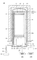
図4及び図5を用いて、基板処理装置200の構成等を具体的に説明する。図4は、本実施形態に係る基板処理装置200を説明する概略縦断面図である。図5は、基板処理装置200を説明する概略横断面図である。
The configuration and the like of the
図4に示すように、基板処理装置200は、直径寸法が例えば300mmの基板Wを棚状に積載するための基板保持具211と、基板保持具211を内部に気密に収納して成膜処理する反応管212(処理室)とを備える。また、基板処理装置200は、反応管212の外側に、内壁面の周方向に配置された加熱部213を備える。更に、基板処理装置200は、水平方向に伸びるベースプレート215を用いて、反応管212及び加熱炉本体214の下端部を支持している。
As shown in FIG. 4, the
基板保持具211は、上下方向に伸びる複数本(例えば3本)の支柱232を備える。ここで、支柱232は、複数の溝部232aを有する。支柱232は、複数の溝部232aを用いて、複数の基板Wをそれぞれの保持位置で保持する。
The
反応管212は、外管212aと外管212aの内部に収納された内管212bとを有する二重管構造である。外管212a及び内管212bは、下面側が開口するように形成されている。外管212aの天井面は外側に膨らむように概略円筒形状に形成されている。内管212bの天井面は水平に形成されている。外管212a及び内管212bの下端面は、フランジ部217によって気密に支持されている。
The
図5に示すように、基板処理装置200は、ガス供給系として、反応管212を上方側から見て時計回り(右回り)に「第1のガスインジェクター251a」、「第2のガスインジェクター251b」及び「第3のガスインジェクター251c」を備える。第1のガスインジェクター251aは、Aガス(例えばジルコニウム(Zr)を含むZr系ガス(原料ガス)、テトラキスエチルメチルアミノジルコニウム(TEMAZr)ガスなど)の貯留源255aに接続されている。第2のガスインジェクター251bは、Bガス(例えばO3(オゾン)ガスなど)の貯留源255bに接続されている。第3のガスインジェクター251cは、Cガス(例えばN2(窒素)ガスなど)の貯留源255cに接続されている。基板処理装置200は、バルブ253及び流量調整部254を用いて、ガスインジェクター251a等から供給するガスの流量を制御する。
As shown in FIG. 5, the
基板処理装置200は、ガスインジェクター251a等を内管212bの外側に膨らんだ部分に収納している。ガスインジェクター251a等は、基板保持具211の長さ方向に沿って配置されると共に、反応管212の周方向に沿って互いに離間するように配置される。ガスインジェクター251a等は、例えば石英の管を用いることができる。
The
基板処理装置200は、ガス排気系として、ガスインジェクター251等に対向する内管212bの側面に、内管212bの長さ方向に沿うようにスリット状の排気口216を有する。また、基板処理装置200は、内管212bと外管212aとの間の領域に連通するように、フランジ部217の側壁に排気口221を有する。基板処理装置200は、圧力調整部223を介して、排気口221から伸びる排気路222と真空ポンプ224とを接続している。基板処理装置200は、排気口216を用いて、ガスインジェクター251a又は251bから供給されたガスを内管212bと外管212aとの間の領域に排気する。
The
本実施形態に係る基板処理装置200は、排気路222に後述する圧力測定器100を備える。これにより、基板処理装置200は、圧力測定器100を用いて、Aガス、Bガス又はCガスを供給された反応管212(処理室)の内圧(圧力)を測定することができる。
The
基板処理装置200は、装置全体の動作をコントロールするコンピュータからなる制御部200Cを備える。制御部200C(のメモリ)は、成膜処理を行うためのプログラムを格納している。このプログラムは、ハードディスク、コンパクトディスク、光磁気ディスク、メモリカード、フレキシブルディスクなどの記憶媒体である記憶部200Mから制御部200C内にインストールされる。
The
以下に、基板処理装置200が実施する処理を説明する。基板処理装置200は、先ず、反応管212の下方側の搬送アーム(不図示)を用いて、基板保持具211に基板W(例えば150枚の12インチ(300mm)サイズの基板)を載置する。次に、基板処理装置200は、基板保持具211を反応管212内に気密に挿入して、真空ポンプ224を用いて反応管212内の雰囲気を真空排気する。また、基板処理装置200は、基板保持具211を鉛直軸周りに回転させながら、ヒータ213を用いて載置した基板Wを加熱する。次いで、基板処理装置200は、圧力測定器100(排気路222)の測定結果を用いて、反応管212内の圧力を処理圧力(例えば1.0Torr(133Pa))に調整しながら、第1のガスインジェクター251aを用いて反応管212内にAガス(第1の処理ガス)を例えば0.4slm(リットル/分)で供給する。このとき、基板Wの表面にAガスが接触すると、基板Wの表面にAガスの原子層あるいは分子層が吸着する。
Below, the process which the
その後、基板処理装置200は、Aガスの供給を停止すると共に、第3のガスインジェクター251cから反応管212内にCガス(パージガス)を例えば20slm〜100slmで供給する。次いで、基板処理装置200は、Cガスの供給を停止し、反応管212内にBガス(第2の処理ガス)を例えば300g/Nm3で供給する。このとき、Bガスは、基板Wに吸着しているAガスの成分と反応し(例えば酸化し)、反応生成物を生成する。更にその後、基板処理装置200は、Bガスの供給を停止し、Cガスを供給して反応管212の雰囲気をパージする。
Thereafter, the
以上のとおり、基板処理装置200は、Aガス(反応ガス)、Cガス(パージガス)、Bガス(反応ガス)及びCガス(パージガス)の供給サイクルを複数回行って、反応生成物の層を基板W表面に積層する。これにより、基板処理装置200は、基板W表面に均一性の高い膜を成膜することができる。
As described above, the
実施例に係る圧力測定器100Eを用いて、本発明を説明する。
The present invention will be described using the
[圧力測定器]
図6を用いて、本実施例に係る圧力測定器100Eの構成等を具体的に説明する。図6は、本実施例に係る圧力測定器100Eを説明する概略断面図である。
[Pressure measuring instrument]
The configuration and the like of the
本実施例に係る圧力測定器100は、第2の実施形態に係る基板処理装置200に用いた場合に、ダイヤフラム11の表面にAガスとBガスとの反応生成物(固体)が析出(又は付着)することを想定して、変化量dHの大きい所定の範囲Rdに反応生成物を析出させることによって、反応生成物によって発生する応力がダイヤフラム11の変形に影響を与えることを低減する。
When the
圧力測定器100Eは、例えば圧力差によるダイヤフラム11の変位量をAとし、反応生成物によって発生した応力による変位量をBとすると、実際の変位量ArはA+Bとなる。また、実際の変位量Arと圧力差による変位量Aとの比は、Ar/A=(A+B)/A=1+B/Aとなる。したがって、本実施例に係る圧力測定器100Eは、圧力差による変位量Aを増加させることによって、比Ar/Aを1に近づけることができる。すなわち、本実施例に係る圧力測定器100Eは、圧力差による変位量Aの値が大きくなるダイヤフラム11の位置に反応生成物を析出(又は付着)させることによって、実際の変位量Arに対する反応生成物の応力による変位量Bの影響を低減することができる。
In the
具体的には、図6に示すように、本実施例に係る圧力測定器100Eは、ダイヤフラム11の直径Dd1を50mmとした。また、圧力測定器100Eは、円形平板23Pを用いて、円環形状のスリットを形成した。ここで、円環形状のスリットは、その中心径Ds1を14.4mmとした。また、円環形状のスリットは、そのスリット幅Ws1を3.2mmとした。すなわち、圧力測定器100Eは、ダイヤフラム11の直径Dd1に対して28.8%の中心径Ds1の円環形状のスリットを形成した。また、圧力測定器100Eは、ダイヤフラム11の直径Dd1に対して6.4%のスリット幅Ws1の円環形状のスリットを形成した。
Specifically, as shown in FIG. 6, in the
[比較例1]
図7(a)は、比較例1に係る圧力測定器301を説明する概略断面図である。
[Comparative Example 1]
FIG. 7A is a schematic cross-sectional view illustrating a
図7(a)に示すように、比較例1に係る圧力測定器301は、ダイヤフラムの直径Ddaを50mmとした。また、比較例1に係る圧力測定器301は、円形平板を用いて円環形状のスリットを形成した。ここで、円環形状のスリットは、その中心径Dsaを29.5mmとした。また、円環形状のスリットは、そのスリット幅Wsaを5.3mmとした。
As shown to Fig.7 (a), the
すなわち、本比較例に係る圧力測定器301は、実施例に係る圧力測定器100Eと比較して、円環形状のスリットの位置が異なる。具体的には、本比較例に係る圧力測定器301は、ダイヤフラムの直径Ddaに対して59%の中心径Dsaの円環形状のスリットを形成した。また、本比較例に係る圧力測定器301は、ダイヤフラムの直径Ddaに対して10.6%のスリット幅Wsaの円環形状のスリットを形成した。この場合、本比較例に係る圧力測定器301は、図7(a)に示す位置に固体DPが付着(又は析出)する。
That is, the
[比較例2]
図7(b)は、比較例2に係る圧力測定器302を説明する概略断面図である。
[Comparative Example 2]
FIG. 7B is a schematic cross-sectional view illustrating the
図7(b)に示すように、比較例2に係る圧力測定器302は、ダイヤフラムの直径Ddbを50mmとした。また、比較例2に係る圧力測定器302は、円形平板を用いない。すなわち、本比較例に係る圧力測定器302は、圧力を測定する空間から流入する気体がダイヤフラムの中心方向に直接供給される。この場合、本比較例に係る圧力測定器302は、図7(b)に示す位置に固体DPが付着(又は析出)する。
As shown in FIG.7 (b), the
[実験]
図8に、本実施例に係る圧力測定器100Eの効果・利点を確認するために行った実験の実験結果の一例を示す。本実験は、本実施例に係る圧力測定器100E(図6)の実験結果L1と比較例の圧力測定器301、302(図7(a)、図7(b))の実験結果La、Lbとを比較した。ここで、図8の横軸は、圧力測定器の使用時間tである。図8の縦軸は、圧力測定器の0点位置を示す無次元数Spである。
[Experiment]
FIG. 8 shows an example of an experimental result of an experiment performed to confirm the effect and advantage of the
図8に示すように、本実施例に係る圧力測定器100Eの実験結果L1は、使用時間tが増加した場合でも、その0点位置の変化量(以下、「シフト量」という。)は小さい値となった。一方、比較例の圧力測定器301、302の実験結果La、Lbは、使用時間tが増加した場合に、そのシフト量が大きい値となった。また、比較例の圧力測定器301、302では、使用時間tの増加とともに、ダイヤフラムに固体が累積し、累積した固体によって加算的にシフト量が増加する傾向となった。
As shown in FIG. 8, the experimental result L1 of the
すなわち、本実施例に係る圧力測定器100Eによれば、使用時間tが増加した場合(ダイヤフラムに固体が付着した場合)でも、シフト量の絶対値を低減することができた。また、本実施例に係る圧力測定器100Eによれば、シフト量が0点位置から変化する方向(以下、「シフト方向」という。)として、マイナスのシフト方向にシフト量を変化させることができた。したがって、本発明を用いることができる圧力測定器は、ダイヤフラムの直径(例えば図6のDd1)に対応する円形平板(例えば図6の23P)の外径(直径)を設定することで、シフト量及び/又はシフト方向を制御(コントロール)することができる。本実施例に係る圧力測定器100Eは、例えば装置の安全性を高めるためにマイナスのシフト方向にシフトさせたい場合には、所定の範囲(図3のRd)より外縁側に固体が付着するように円形平板の外径を決定することができる。また、本実施例に係る圧力測定器100Eは、例えばプラスのシフト方向にシフトさせたい場合には、所定の範囲(図3のRd)より中心側に固体が付着するように円形平板の外径を決定することができる。
That is, according to the
以上のとおり、本実施例に係る圧力測定器100Eでは、比較例の圧力測定器301、302と比較して、ダイヤフラムに付着(又は析出)した固体によって発生する応力がシフト量に与える影響を低減することができる。また、本実施例に係る圧力測定器100Eによれば、ダイヤフラムに固体が付着した場合でもシフト量が小さい値となるため、ダイヤフラムの変形に基づいて高精度に圧力を測定することができる。更に、本実施例に係る圧力測定器100Eによれば、原子層成膜法を用いて基板処理する装置において、処理室内の圧力を測定する場合に、互いに反応する2種類のガスが交互にダイヤフラム表面と接触し、ダイヤフラム表面に2種類のガスの反応生成物が析出する場合でも、析出した反応生成物によって発生する応力がシフト量に与える影響を低減することができる。
As described above, in the
以上、本発明の圧力測定器又はその圧力測定器を備える基板処理装置に係る実施形態及び実施例を参照しながら、本発明を説明したが、本発明は上記の実施形態及び実施例に限定されることなく、添付の特許請求の範囲に照らし、種々に変更又は変形することが可能である。 The present invention has been described above with reference to the embodiments and examples of the pressure measuring instrument of the present invention or the substrate processing apparatus including the pressure measuring instrument. However, the present invention is limited to the above-described embodiments and examples. Without departing from the scope of the invention, various changes and modifications can be made in light of the appended claims.
100、100E : 圧力測定器
200 : 基板処理装置
10、11 : ダイヤフラム
10A: 基準圧力室
10B: 測定圧力室
21 : 検出部
22 : 連通部
23 : 円環流路形成部
23P: 円形平板
23Pa:円形の開口
Dd、Dd1 : ダイヤフラムの外径(第1の連通部の内径)
Ds、Ds1 : 円環形状の通路の中心径
Ws、Ws1 : 円環形状の通路の幅
Rd : 所定の範囲
f1、f2 : ダイヤフラムに作用する応力
100, 100E: Pressure measuring device 200: Substrate processing apparatus 10, 11:
Ds, Ds1: Central diameter of the annular passage Ws, Ws1: Width of the annular passage Rd: Predetermined range f1, f2: Stress acting on the diaphragm
Claims (6)
前記基準圧力室を内部に備える検出部と、
前記ダイヤフラムと前記測定圧力室とを連通する連通部と、
前記検出部と前記連通部との間に配置され、略円環形状の通路を形成する円環流路形成部と
を有し、
前記検出部は、円筒形状であり、該円筒形状の内部に前記ダイヤフラムを配置され、
前記連通部は、前記検出部の該円筒形状の内径より小さい内径を有する円管形状であり、前記測定圧力室の気体を前記略円環形状の通路に流入させ、
前記円環流路形成部は、前記連通部から流入する気体を前記略円環形状の通路に通過させ、通過させた気体を前記ダイヤフラムの側面に供給し、
前記略円環形状の通路は、前記ダイヤフラムの単位面積当たりの変位量の微分値が最大値となる位置と対向する位置に形成される、
ことを特徴とする圧力測定器。 A pressure measuring instrument that measures the pressure of the measurement pressure chamber by detecting deformation of the diaphragm using a diaphragm disposed at a boundary between a reference pressure chamber and a measurement pressure chamber,
A detection unit having the reference pressure chamber therein;
A communication portion for communicating the diaphragm and the measurement pressure chamber;
An annular flow path forming portion that is disposed between the detection portion and the communication portion and forms a substantially annular passage;
The detection unit has a cylindrical shape, and the diaphragm is disposed inside the cylindrical shape,
The communication portion has a circular tube shape having an inner diameter smaller than the inner diameter of the cylindrical shape of the detection portion, and allows the gas in the measurement pressure chamber to flow into the substantially annular passage,
The annular flow path forming portion passes the gas flowing in from the communication portion through the substantially annular passage, and supplies the passed gas to the side surface of the diaphragm.
The substantially ring-shaped passage is formed at a position facing a position where a differential value of a displacement amount per unit area of the diaphragm is a maximum value.
A pressure measuring device characterized by that.
前記円形平板の外径は、前記検出部の内径又は前記ダイヤフラムの外径に対して10%から30%の範囲内の大きさである、ことを特徴とする、請求項1又は請求項2に記載の圧力測定器。 The annular flow path forming portion includes a circular flat plate,
The outer diameter of the circular flat plate has a size within a range of 10% to 30% with respect to the inner diameter of the detection unit or the outer diameter of the diaphragm. The pressure measuring instrument described.
前記測定圧力室と連通する処理室で基板を処理する基板処理手段と、
を有する基板処理装置。 A pressure measuring device according to any one of claims 1 to 5;
Substrate processing means for processing a substrate in a processing chamber communicating with the measurement pressure chamber;
A substrate processing apparatus.
Priority Applications (3)
| Application Number | Priority Date | Filing Date | Title |
|---|---|---|---|
| JP2013005777A JP5993312B2 (en) | 2013-01-16 | 2013-01-16 | Pressure measuring instrument and substrate processing apparatus including the pressure measuring instrument |
| KR1020140000821A KR101810729B1 (en) | 2013-01-16 | 2014-01-03 | Pressure measuring instrument and substrate processing apparatus with the pressure measuring instrument |
| US14/150,457 US9360390B2 (en) | 2013-01-16 | 2014-01-08 | Pressure measuring instrument and substrate processing apparatus provided with the pressure measuring instrument |
Applications Claiming Priority (1)
| Application Number | Priority Date | Filing Date | Title |
|---|---|---|---|
| JP2013005777A JP5993312B2 (en) | 2013-01-16 | 2013-01-16 | Pressure measuring instrument and substrate processing apparatus including the pressure measuring instrument |
Publications (3)
| Publication Number | Publication Date |
|---|---|
| JP2014137275A JP2014137275A (en) | 2014-07-28 |
| JP2014137275A5 JP2014137275A5 (en) | 2016-05-19 |
| JP5993312B2 true JP5993312B2 (en) | 2016-09-14 |
Family
ID=51164152
Family Applications (1)
| Application Number | Title | Priority Date | Filing Date |
|---|---|---|---|
| JP2013005777A Active JP5993312B2 (en) | 2013-01-16 | 2013-01-16 | Pressure measuring instrument and substrate processing apparatus including the pressure measuring instrument |
Country Status (3)
| Country | Link |
|---|---|
| US (1) | US9360390B2 (en) |
| JP (1) | JP5993312B2 (en) |
| KR (1) | KR101810729B1 (en) |
Cited By (1)
| Publication number | Priority date | Publication date | Assignee | Title |
|---|---|---|---|---|
| JP2020034325A (en) * | 2018-08-28 | 2020-03-05 | 株式会社エー・アンド・デイ | Pressure sensor |
Families Citing this family (9)
| Publication number | Priority date | Publication date | Assignee | Title |
|---|---|---|---|---|
| US9429110B2 (en) | 2013-01-16 | 2016-08-30 | Ford Global Technologies, Llc | Method and system for vacuum control |
| JP6727871B2 (en) | 2016-03-18 | 2020-07-22 | 東京エレクトロン株式会社 | Exhaust system and substrate processing apparatus using the same |
| CN106197828B (en) * | 2016-06-28 | 2019-01-01 | 蚌埠大洋传感系统工程有限公司 | A kind of sensor that accuracy is high |
| CN106197825B (en) * | 2016-06-28 | 2018-10-12 | 蚌埠大洋传感系统工程有限公司 | A kind of sensor for measuring pressure |
| CN106197827B (en) * | 2016-06-28 | 2019-01-01 | 蚌埠大洋传感系统工程有限公司 | A kind of accurate sensor of measurement |
| CN106197826B (en) * | 2016-06-28 | 2018-10-12 | 蚌埠大洋传感系统工程有限公司 | A kind of high-precision sensor |
| US10310028B2 (en) * | 2017-05-26 | 2019-06-04 | Allegro Microsystems, Llc | Coil actuated pressure sensor |
| JP7330060B2 (en) * | 2019-10-18 | 2023-08-21 | 東京エレクトロン株式会社 | Deposition apparatus, control apparatus, and method for adjusting pressure gauge |
| CN110987282A (en) * | 2019-11-29 | 2020-04-10 | 中国科学院微电子研究所 | Anti-deposition air homogenizing ring |
Family Cites Families (9)
| Publication number | Priority date | Publication date | Assignee | Title |
|---|---|---|---|---|
| US5811685A (en) * | 1996-12-11 | 1998-09-22 | Mks Instruments, Inc. | Fluid pressure sensor with contaminant exclusion system |
| JP3494594B2 (en) * | 1999-08-05 | 2004-02-09 | 忠弘 大見 | Pressure detector mounting structure |
| US7252011B2 (en) * | 2002-03-11 | 2007-08-07 | Mks Instruments, Inc. | Surface area deposition trap |
| US7253107B2 (en) * | 2004-06-17 | 2007-08-07 | Asm International N.V. | Pressure control system |
| US7204150B2 (en) * | 2005-01-14 | 2007-04-17 | Mks Instruments, Inc. | Turbo sump for use with capacitive pressure sensor |
| US20100162952A1 (en) | 2005-09-27 | 2010-07-01 | Hitachi Kokusai Electric Inc. | Substrate processing apparatus |
| US7765874B2 (en) | 2006-01-18 | 2010-08-03 | Inficon Gmbh | Vacuum measuring cell with membrane |
| US7707891B2 (en) | 2008-06-27 | 2010-05-04 | Inficon Gmbh | Optical interferometric pressure sensor |
| SG10201509452UA (en) * | 2011-10-11 | 2015-12-30 | Mks Instr Inc | Pressure sensor |
-
2013
- 2013-01-16 JP JP2013005777A patent/JP5993312B2/en active Active
-
2014
- 2014-01-03 KR KR1020140000821A patent/KR101810729B1/en active IP Right Grant
- 2014-01-08 US US14/150,457 patent/US9360390B2/en active Active
Cited By (2)
| Publication number | Priority date | Publication date | Assignee | Title |
|---|---|---|---|---|
| JP2020034325A (en) * | 2018-08-28 | 2020-03-05 | 株式会社エー・アンド・デイ | Pressure sensor |
| JP7002821B2 (en) | 2018-08-28 | 2022-01-20 | 株式会社エー・アンド・デイ | Pressure sensor |
Also Published As
| Publication number | Publication date |
|---|---|
| US9360390B2 (en) | 2016-06-07 |
| JP2014137275A (en) | 2014-07-28 |
| KR20140092762A (en) | 2014-07-24 |
| KR101810729B1 (en) | 2017-12-19 |
| US20140196545A1 (en) | 2014-07-17 |
Similar Documents
| Publication | Publication Date | Title |
|---|---|---|
| JP5993312B2 (en) | Pressure measuring instrument and substrate processing apparatus including the pressure measuring instrument | |
| US11725277B2 (en) | Pressure transmitter for a semiconductor processing environment | |
| CN108458828B (en) | Capacitance type pressure sensor | |
| US20130267100A1 (en) | Method of manufacturing semiconductor device, substrate processing apparatus and evaporation system | |
| US20140251209A1 (en) | Support member and semiconductor manufacturing apparatus | |
| TWI773705B (en) | Methods, systems and apparatus for enhanced flow detection repeatability of thermal-based mass flow controllers (mfcs) | |
| US10094022B2 (en) | Substrate processing apparatus and method of fabricating substrate loading unit | |
| EP2593580B1 (en) | Process chamber pressure control system and method | |
| JP6758163B2 (en) | Board processing equipment | |
| KR102247946B1 (en) | Substrate processing apparatus | |
| CN111850512A (en) | Film forming method and film forming apparatus | |
| TW202117065A (en) | Gas introduction structure, heattreatment device, and gas supply method | |
| CN108389770B (en) | Ozone gas heating mechanism, substrate processing apparatus, and substrate processing method | |
| US20220411933A1 (en) | Film forming apparatus | |
| US12024776B2 (en) | Gas supply apparatus, gas supply method, and substrate processing apparatus | |
| WO2009096379A1 (en) | Heating device for pressure measurement and pressure measuring device | |
| JPWO2019181397A1 (en) | Diaphragm valve and mass flow control device using it | |
| US20220356581A1 (en) | Gas supply device and gas supply method | |
| US20240124972A1 (en) | Canister, precursor transfer system having the same and method for measuring precursor remaining amount thereof | |
| KR20170078068A (en) | Exhaust sysyem of atomic layer deposition apparatus | |
| JP2021014614A (en) | Substrate treatment method and substrate treatment apparatus |
Legal Events
| Date | Code | Title | Description |
|---|---|---|---|
| A621 | Written request for application examination |
Free format text: JAPANESE INTERMEDIATE CODE: A621 Effective date: 20150619 |
|
| A521 | Request for written amendment filed |
Free format text: JAPANESE INTERMEDIATE CODE: A523 Effective date: 20160329 |
|
| A977 | Report on retrieval |
Free format text: JAPANESE INTERMEDIATE CODE: A971007 Effective date: 20160525 |
|
| A131 | Notification of reasons for refusal |
Free format text: JAPANESE INTERMEDIATE CODE: A131 Effective date: 20160531 |
|
| A521 | Request for written amendment filed |
Free format text: JAPANESE INTERMEDIATE CODE: A523 Effective date: 20160622 |
|
| TRDD | Decision of grant or rejection written | ||
| A01 | Written decision to grant a patent or to grant a registration (utility model) |
Free format text: JAPANESE INTERMEDIATE CODE: A01 Effective date: 20160809 |
|
| A61 | First payment of annual fees (during grant procedure) |
Free format text: JAPANESE INTERMEDIATE CODE: A61 Effective date: 20160819 |
|
| R150 | Certificate of patent or registration of utility model |
Ref document number: 5993312 Country of ref document: JP Free format text: JAPANESE INTERMEDIATE CODE: R150 |
|
| R250 | Receipt of annual fees |
Free format text: JAPANESE INTERMEDIATE CODE: R250 |
|
| R250 | Receipt of annual fees |
Free format text: JAPANESE INTERMEDIATE CODE: R250 |
|
| R250 | Receipt of annual fees |
Free format text: JAPANESE INTERMEDIATE CODE: R250 |
|
| R250 | Receipt of annual fees |
Free format text: JAPANESE INTERMEDIATE CODE: R250 |
|
| R250 | Receipt of annual fees |
Free format text: JAPANESE INTERMEDIATE CODE: R250 |
|
| R250 | Receipt of annual fees |
Free format text: JAPANESE INTERMEDIATE CODE: R250 |