JP5987714B2 - Metal workpiece processing method - Google Patents
Metal workpiece processing method Download PDFInfo
- Publication number
- JP5987714B2 JP5987714B2 JP2013018748A JP2013018748A JP5987714B2 JP 5987714 B2 JP5987714 B2 JP 5987714B2 JP 2013018748 A JP2013018748 A JP 2013018748A JP 2013018748 A JP2013018748 A JP 2013018748A JP 5987714 B2 JP5987714 B2 JP 5987714B2
- Authority
- JP
- Japan
- Prior art keywords
- groove
- workpiece
- metal workpiece
- forming
- protrusion
- Prior art date
- Legal status (The legal status is an assumption and is not a legal conclusion. Google has not performed a legal analysis and makes no representation as to the accuracy of the status listed.)
- Active
Links
Images


Landscapes
- Mechanical Operated Clutches (AREA)
Description
本発明は、金属製ワークに転造加工により突条部を形成した後、該突条部の頂面部に、プレス加工により、該突条部を横切るように溝部を形成する、金属製ワークの加工方法に関する技術分野に属する。 The present invention provides a metal workpiece in which, after forming a ridge portion by rolling on a metal workpiece, a groove is formed on the top surface of the ridge portion so as to cross the ridge portion by pressing. It belongs to the technical field related to processing methods.
一般に、自動車の自動変速機に用いられるクラッチドラムを成形する場合、転造加工により、金属製の円筒状ワークの内周面にスプライン歯を形成し、その後、プレス加工により、全てのスプライン歯の頂面部に、該スプライン歯を横切るようにスナップリング用溝部を形成する。スナップリング用溝部にはスナップリングが嵌められる。このスナップリングは、クラッチドラムと該クラッチドラムの内側に配設されかつ外周側にスプライン歯が形成されたクラッチハブとの間において軸方向に交互に配設されたクラッチ板及び摩擦板の抜け止めとされ、クラッチ板及び摩擦板が互いの係合のためにスナップリングの側に押圧されるときの押圧力を受け止める。 Generally, when forming a clutch drum used in an automatic transmission of an automobile, spline teeth are formed on the inner peripheral surface of a metal cylindrical workpiece by rolling, and then all spline teeth are formed by pressing. A snap ring groove is formed on the top surface so as to cross the spline teeth. A snap ring is fitted into the groove for the snap ring. The snap ring prevents the clutch plate and the friction plate, which are alternately disposed in the axial direction, between the clutch drum and the clutch hub disposed inside the clutch drum and having spline teeth formed on the outer peripheral side. And receives the pressing force when the clutch plate and the friction plate are pressed to the snap ring side for mutual engagement.
ところが、スナップリング用溝部を形成する際、プレス加工によりワーク材料を径方向外側に押し込むので、押し込まれて形成されたスナップリング用溝部の底壁面部(特に、該底壁面部に対して軸方向に隣接する押し込まれない部分との境界部分)にクラックが生じる可能性がある。特に、スナップリングの引っ掛かり代を大きくするべく、スナップリング用溝部の深さを深くすると、クラックがより一層生じ易くなる。このようなクラックが生じると、スナップリング用溝部の側壁面部にスナップリングを介して上記押圧力が作用したときに、スナップリング用溝部の壁面部が破断して、スナップリングが上記押圧力を受け止めることができなくなるという問題が生じる。 However, when forming the snap ring groove, the work material is pushed radially outward by pressing, so that the bottom wall surface portion of the snap ring groove portion formed by pressing (particularly, axial direction relative to the bottom wall surface portion). There is a possibility that a crack may occur at a boundary part between the part not adjacent to the part and not pushed in. In particular, if the depth of the snap ring groove is increased in order to increase the snap ring catch, cracks are more likely to occur. When such a crack occurs, when the pressing force acts on the side wall surface portion of the snap ring groove portion via the snap ring, the wall surface portion of the snap ring groove portion breaks, and the snap ring receives the pressing force. The problem of being unable to do so arises.
そこで、例えば特許文献1では、クラッチドラムにおけるスナップリング当接部の裏側(径方向外側)で構成する棚状部面の一部に、該棚状部面上からクラッチドラムの開口端側の外周壁に向かって延在する肉厚部を突出形成することによって、スナップリング用溝部におけるクラッチドラム開口端側壁部と棚状部との間に渡る梁構造を形成して、肉厚部においてクラックが生じるのを防止している。
Therefore, in
上記特許文献1のような肉厚部を形成すれば、その肉厚部によって、スナップリング用溝部の壁面部が破断するのを防止することができるが、本発明者らは、上記肉厚部を形成しなくても、そのような効果が得られる方法を見出した。
If the thick portion as in
本発明は、斯かる点に鑑みてなされたものであり、その目的とするところは、金属製ワークに転造加工により突条部を形成した後、該突条部の頂面部に、プレス加工により、該突条部を横切るように溝部を形成する場合に、溝部の側壁面部に対して溝部の幅方向に押圧力が作用しても、溝部の壁面部が破断するのを防止しようとすることにある。 The present invention has been made in view of such points, and the object of the present invention is to form a protrusion on a metal workpiece by rolling, and then press the top surface of the protrusion. Thus, when the groove is formed so as to cross the protrusion, even if a pressing force acts on the side wall surface of the groove in the width direction of the groove, the wall surface of the groove is prevented from breaking. There is.
上記の目的を達成するために、本発明では、金属製ワークに転造加工により突条部を形成した後、該突条部の頂面部に、プレス加工により、該突条部を横切るように溝部を形成する、金属製ワークの加工方法を対象として、転造加工により、上記金属製ワークに上記突条部を形成すると同時に、該突条部の頂面部における幅方向中央部であって少なくとも上記溝部の形成予定領域に、該溝部の深さ以下の所定深さを有する凹部を形成する凹部形成工程と、上記凹部形成工程の後、上記突条部の頂面部における上記溝部の形成予定領域に、プレス加工により上記溝部を形成する溝部形成工程とを含むようにした。 In order to achieve the above object, in the present invention, after forming a ridge portion by rolling on a metal workpiece, the top surface portion of the ridge portion is crossed by the press processing. For the method of processing a metal workpiece that forms a groove, at the same time as forming the protrusion on the metal workpiece by rolling, at the same time, at least in the widthwise central portion of the top surface of the protrusion in the groove forming area of the concave portion forming step of forming a recess having a predetermined depth depth below the groove portion, after the recess forming step, the forming schedule of the groove area at the top surface of the ridge And a groove portion forming step of forming the groove portion by press working.
上記方法により、凹部形成工程で、突条部の頂面部における幅方向中央部であって少なくとも溝部の形成予定領域に、凹部が形成され、この後、溝部形成工程で、突条部の頂面部における溝部の形成予定領域に、プレス加工により溝部が形成される。 By the method described above, in the concave portion forming step, at least the groove forming region of a widthwise central portion of the top wall of the ridge, recess is formed, thereafter, in the groove forming step, the top surface of the ridge the formation region of the groove in the groove is formed by pressing.
上記凹部は、転造加工により突条部の形成と同時に形成されるので、凹部の壁面部にクラックが生じることはない。また、凹部は突条部の頂面部における幅方向中央部に形成されるので、突条部の幅方向両側の側面が他の部材と係合する係合面であったとしても、凹部の形成が、突条部の幅方向両側面に対して悪影響を及ぼすことはない。 Since the concave portion is formed simultaneously with the formation of the protruding portion by rolling, no crack is generated in the wall surface portion of the concave portion. In addition, since the concave portion is formed in the central portion in the width direction of the top surface portion of the ridge portion, the concave portion is formed even if the side surfaces on both sides in the width direction of the ridge portion are engaging surfaces that engage with other members. However, it does not adversely affect both side surfaces of the protrusion in the width direction.
上記溝部は、突条部の頂面部における溝部の形成予定領域において凹部形成領域(幅方向中央部)とこの凹部形成領域に対して突条部の幅方向両側の領域に形成されることになる。上記凹部形成領域では、プレス加工による溝部形成のための押し込み量は少なくて済む。特に凹部が溝部の深さと同じ深さを有していれば、上記押し込み量は0となる。この結果、凹部の所定深さを適切に設定することで、溝部の底壁面部における凹部形成領域に対応する部分では、突条部の延びる方向に沿った材料の繋がりを確保することができ、クラックが生じるのを防止することができる。一方、上記溝部の形成予定領域において凹部形成領域に対して突条部の幅方向両側の領域では、プレス加工による溝部形成のための押し込み量は溝部の深さと同じになり、溝部の底壁面部において凹部形成領域の両側領域に対応する部分(特に、該部分に対して突条部の延びる方向に隣接する押し込まれない部分との境界部分)にクラックが生じる可能性があるが、たとえクラックが生じても、溝部の底壁面部における凹部形成領域に対応する部分ではクラックが生じていないため、溝部の壁面部全体としては強度が確保され、溝部の側壁面部に対して溝部の幅方向に押圧力が作用しても、溝部の壁面部が破断するのを防止することができる。尚、溝部の側壁面部は、凹部形成領域に対応する部分では、存在しないか又は高さが低くなるため、上記押圧力は、基本的に、溝部の側壁面部における凹部形成領域の両側領域に対応する部分に作用することになるが、上記のように溝部の壁面部全体として強度が確保されているので、溝部の壁面部が破断することはない。 The groove portion is formed in a region where the groove portion is to be formed on the top surface portion of the ridge portion and in a region on both sides in the width direction of the ridge portion with respect to the recessed portion formation region (width direction center portion). . In the recessed portion forming region, the amount of pushing for forming the groove portion by press working may be small. In particular, if the recess has the same depth as the groove, the amount of pushing will be zero. As a result, by appropriately setting the predetermined depth of the concave portion, in the portion corresponding to the concave portion formation region in the bottom wall surface portion of the groove portion, it is possible to ensure the connection of the material along the direction in which the ridge portion extends, Cracks can be prevented from occurring. On the other hand, in the both sides in the width direction of the region of the ridges relative to the recess forming region in the forming region of the groove, the pressing amount for groove formation by press working the same as the depth of the groove bottom of the groove wall portion Cracks may occur in portions corresponding to both side regions of the recess formation region (especially, a boundary portion with a portion not pressed in adjacent to the portion in the direction in which the protruding portion extends). Even if it occurs, since the crack does not occur in the portion corresponding to the recess forming region in the bottom wall surface portion of the groove portion, the strength of the entire wall surface portion of the groove portion is ensured, and the wall surface portion of the groove portion is pushed in the width direction of the groove portion. Even when pressure acts, it is possible to prevent the wall surface of the groove from breaking. Note that the side wall surface portion of the groove portion does not exist in the portion corresponding to the concave portion formation region or the height thereof is low, so the above pressing force basically corresponds to both side regions of the concave portion formation region in the side wall surface portion of the groove portion. However, since the strength of the entire wall surface portion of the groove portion is ensured as described above, the wall surface portion of the groove portion is not broken.
本発明の一実施形態によれば、上記金属製ワークは、円筒状ワークであり、上記突条部は、上記円筒状ワークの内周面に形成される複数のスプライン歯であり、上記溝部は、上記複数のスプライン歯の頂面部に形成された、スナップリングが嵌められるスナップリング用溝部である。 According to an embodiment of the present invention, the metal workpiece is a cylindrical workpiece, the protruding portion is a plurality of spline teeth formed on an inner peripheral surface of the cylindrical workpiece, and the groove portion is , A snap ring groove formed on the top surface of the plurality of spline teeth and fitted with a snap ring.
このことにより、クラッチドラムのような、スプライン歯とスナップリング用溝部とを有する部材を容易に成形することができるとともに、スナップリング用溝部に嵌められたスナップリングに軸方向に押圧力が作用したときに、その押圧力を安定して受け止めることができるようになる。 As a result, a member having spline teeth and a snap ring groove, such as a clutch drum, can be easily formed, and a pressing force is applied in the axial direction to the snap ring fitted in the snap ring groove. Sometimes, the pressing force can be received stably.
以上説明したように、本発明の金属製ワークの加工方法によると、転造加工により、金属製ワークに突条部を形成すると同時に、突条部の頂面部における幅方向中央部であって少なくとも溝部の形成予定領域に凹部を形成し、その後、突条部の頂面部における溝部の形成予定領域に、プレス加工により溝部を形成したことにより、溝部の側壁面部に対して溝部の幅方向に押圧力が作用しても、溝部の壁面部が破断するのを防止することができる。 As described above, according to the method for processing a metal workpiece of the present invention, at the same time as forming the ridge portion on the metal workpiece by rolling, at least the widthwise central portion of the top surface portion of the ridge portion, A recess is formed in the region where the groove is to be formed, and then the groove is formed by pressing in the region where the groove is to be formed in the top surface of the ridge, thereby pushing the side wall surface of the groove in the width direction of the groove. Even when pressure acts, it is possible to prevent the wall surface of the groove from breaking.
以下、本発明の実施形態を図面に基づいて詳細に説明する。 Hereinafter, embodiments of the present invention will be described in detail with reference to the drawings.
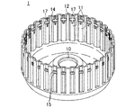
図1は、本発明の実施形態に係る加工方法により製造された金属製のクラッチドラム1を示す。このクラッチドラム1は、一端が開放された有底円筒状をなし、その底部には、クラッチドラム1を支持する軸部材を通す軸孔10が設けられている。クラッチドラム1の円筒部の内周面には、該円筒部の軸方向に延びかつ内側に突出した突条部としての複数のスプライン歯11が上記円筒部の周方向に等間隔をあけて並ぶように形成されている。相隣接する2つのスプライン歯11の間は、スプライン溝12とされている。
FIG. 1 shows a
クラッチドラム1の円筒部の内周面における開放端の近傍には、スナップリングが嵌められるスナップリング用溝部14(以下、溝部14という)が形成されている。この溝部14は、上記円筒部の周方向に延びていて、該円筒部の内周面全周に亘って設けられるが、溝部14の深さがスプライン溝12にまでは及ばないので、実際にはスプライン歯11のみに設けられている。溝部14は、上記円筒部の軸方向に延びる各スプライン歯11を横切るように該円筒部の周方向に延びていることになる。尚、上記円筒部の外周面において溝部14の底壁面部における凹部17が形成されていない領域に対応する部分には、後述の如く溝部14を形成する際に生じる突出部15が形成されている。
Near the open end of the inner peripheral surface of the cylindrical portion of the
上記スナップリングは、クラッチドラム1と該クラッチドラム1の内側に配設されかつ外周側にスプライン歯が形成されたクラッチハブとの間において上記円筒部の軸方向に交互に配設されたクラッチ板及び摩擦板の抜け止めとされ、クラッチ板及び摩擦板が互いの係合のために上記スナップリングの側に押圧されるときの押圧力を受け止める。クラッチ板及び摩擦板の一方は、クラッチドラム1のスプライン歯と上記円筒部の軸方向に移動可能に係合し、他方は、クラッチハブのスプライン歯と上記円筒部の軸方向に移動可能に係合しており、クラッチ板と摩擦板とが互いに係合したとき、クラッチドラム1とクラッチハブとが一体回転することになる。
The snap rings are arranged alternately between the
本実施形態では、図1及び図2に示すように、各スプライン歯11の歯先面部の歯厚方向(上記円筒部の周方向)の中央部、つまり突条部の頂面部における幅方向中央部に、上記円筒部の軸方向に延びる溝状の凹部17が形成されている。この凹部17は、本実施形態では、上記円筒部の開放端から溝部14を超えて底部側へ延びている。凹部17は、溝部14の形成前に、転造加工により、スプライン歯11と同時に、スプライン歯11の歯先面部における歯厚方向中央部(突条部の頂面部における幅方向中央部)であって溝部14の形成予定領域及び該形成予定領域に対して上記円筒部の軸方向両側部分に形成したものである。凹部17は、溝部14の深さ以下の所定深さ(本実施形態では、溝部14の深さと同じ深さ)を有する。
In this embodiment, as shown in FIGS. 1 and 2, the center in the tooth thickness direction (circumferential direction of the cylindrical portion) of the tip surface portion of each
尚、複数のスプライン溝12のうちの一部のスプライン溝12(上記円筒部の軸方向において溝部14よりも底部側)には、図示を省略する油孔が形成されており、この油孔から自動変速機油(ATF)がクラッチドラム1の円筒部外に排出されるようになっている。
An oil hole (not shown) is formed in a part of the plurality of spline grooves 12 (on the bottom side of the
次に、上記クラッチドラム1の製造方法について説明する。
Next, a method for manufacturing the
先ず、図3(a)に示すように、金属板に対して、不図示のプレス装置によって打ち抜き加工と絞り加工とを施して、転造加工を施す対象である金属製ワークWを作製する。このワークWは、クラッチドラム1の基本的な形状である有底円筒状をなしており、このワークWの底部には軸孔10が形成されている。ワークWにおける円筒部の軸方向の長さは、完成寸法よりも短く、該円筒部は余剰な板厚を有している。
First, as shown in FIG. 3A, a metal workpiece W, which is a subject to be subjected to a rolling process, is manufactured by subjecting a metal plate to punching and drawing using a pressing device (not shown). The work W has a bottomed cylindrical shape that is a basic shape of the
続いて、図3(b)に示すように、ワークWの円筒部の内周面に、転造加工によりスプライン歯11及びスプライン溝12を形成する。この転造加工は、スプライン成形装置20により行う。このスプライン成形装置20は、スプライン歯11に対応する複数の歯部と該各歯部の歯先面にそれぞれ設けられかつ凹部17に対応する凸部とが形成された外周部21aを有するマンドレル21と、外周面に、歯形を有する突部が形成された転造ローラ22とを備える。
Subsequently, as shown in FIG. 3B,
転造ローラ22は、回転ヘッド23に回転自在に支持されて転造ローラ22自身の回転軸を中心に自転するようにr1方向に回転可能であるとともに、回転ヘッド23が回転することによってマンドレル21に対して近接と離間とを繰り返しながら、回転ヘッド23の回転軸23aの周りを公転するようにr2方向に回転可能である。また、1つの回転ヘッド23に対して2つの転造ローラ22(1つの転造ローラ22であってもよい)が支持されており、この回転ヘッド23は、マンドレル21を径方向に挟んで対向するように一対(2つ)配置され、一対の回転ヘッド23は互いに反対方向に回転可能である。尚、回転ヘッド23が1つであってもよい。
The rolling
上記スプライン成形装置20によりワークWにスプライン歯11を形成するには、先ず、ワークWの円筒部の内側にマンドレル21を挿入して、固定具24によりワークWをマンドレル21に固定する(図3(b)参照)。
In order to form the
続いて、転造ローラ22の公転周期とマンドレル21の軸方向d1及び周方向d2への送り量及び送り速度とを同期させながら、転造ローラ22の突部によりワークWの円筒部をマンドレル21の外周部21aに対して押圧することによって、転造ローラ22の突部とマンドレル21の外周部21aとの間でスプライン歯11及び凹部17を同時に形成する。凹部17は、溝部14の深さと同じ深さを有していて、スプライン歯11の歯先面部における歯厚方向中央部であって溝部14の形成予定領域及び該形成予定領域に対してワークWの円筒部の軸方向両側部分に形成される。
Subsequently, the cylindrical portion of the workpiece W is moved by the protrusion of the rolling
次いで、上記スプライン歯11の歯先面部における溝部14の形成予定領域に、プレス加工により溝部14を形成するとともに、一部のスプライン溝12に油孔を形成する。また、ワークWの開放端側の有効範囲以外の部分を切断する。すなわち、上記スプライン成形装置20による転造加工の際に、ワークWはその円筒部の軸方向及び周方向に伸びるように変形するため、その軸方向に伸びた部分を切除する。尚、ワークWの周方向に伸びた分は、予め試験等により伸び量を予測しておき、この予測された伸び量を見込んでマンドレル21の外周部21aの形状を決定している。こうしてクラッチドラム1が完成する。
Next, the
上記溝部14の形成は、図4〜図6に示すように、ダイ30及びパンチ40によって行う。ダイ30は、不図示の回転テーブルに載せられたワークWの円筒部の径方向外側に位置していて、不図示の駆動機構により、ワークWに対して離接する方向(ワークWの円筒部の径方向)に移動可能である。ダイ30は、ワークWの円筒部の軸方向から見て、ワークWの円筒部の凹凸に対応した形状をなしていて、ワークWの円筒部の外周面に略密着することが可能である。ダイ30におけるワークWの円筒部の外周面に略密着する面には、溝部14の形成時に突出して生じる上記突出部15に対応して、凹陥部30a(図6参照)が形成されている。一方、パンチ40は、上記ワークWの円筒部の径方向内側に位置していて、不図示の駆動機構により、ワークWに対して離接する方向(ワークWの円筒部の径方向)に移動可能である。そして、ダイ30がワークWの円筒部の外周面に略密着した状態にあるとき、パンチ40がワークWの円筒部の内周面(スプライン歯11の歯先面部における溝部14の形成予定領域)を押圧することで、スプライン歯11の歯先面部における溝部14の形成予定領域に、溝部14を形成する。
The
本実施形態では、一度に2つのスプライン歯11の歯先面部に溝部14を形成する。2つのスプライン歯11に溝部14を形成した後、ダイ30及びパンチ40をワークWから離し、その後、上記回転テーブルを回転させて次の2つのスプライン歯11が、ダイ30及びパンチ40の間に位置するようにし、次いで、ダイ30及びパンチ40によって、上記と同様に、次の2つのスプライン歯11に同時に溝部14を形成する。この動作を繰り返して、全てのスプライン歯11に溝部14を形成し、こうして溝部14の形成が完了する。
In this embodiment, the
上記溝部14の形成の際、上記溝部14の形成予定領域において凹部17が形成されていない領域(凹部17に対してスプライン歯11の歯厚方向両側の領域)では、プレス加工による溝部14形成のための押し込み量は溝部14の深さと同じになり、図6に示すように、溝部14の底壁面部がワークWの円筒部の径方向外側に突出して突出部15が形成される。このとき、溝部14の底壁面部において凹部17が形成されていない領域に対応する部分(突出部15)、特に、突出部15に対してワークWの円筒部の軸方向に隣接する押し込まれない部分との境界部分(図6の×印の部分)に、クラックが生じる可能性がある。仮に溝部14の形成前に凹部17が形成されていなかったとすると、溝部14の底壁面部の周方向全体が径方向外側に突出するため、溝部14の底壁面部の周方向全体に亘って、ワークWの円筒部の軸方向に沿った材料の繋がりを確保することが困難になる。
In the formation of the
これに対し、本実施形態では、溝部14の形成前に凹部17が形成されており、上記溝部14の形成予定領域において凹部17の形成領域では、プレス加工による溝部14の形成のための押し込み量は0である(図5参照)。この結果、溝部14の底壁面部における凹部17の形成領域に対応する部分(該部分は、その両側の突出部15に引っ張られて僅かに径方向外側に突出するようになっている(図5ではその突出を省略しているが、図2及び図4には記載している))では、ワークWの円筒部の軸方向に沿った材料の繋がりを確保することができ、クラックが生じるのを防止することができる。これにより、溝部14の底壁面部において凹部17が形成されていない領域に対応する部分(突出部15)にクラックが生じたとしても、溝部14の壁面部全体としては強度が確保される。したがって、溝部14に嵌められたスナップリングを介して、溝部14の側壁面部に対して溝部14の幅方向(クラッチドラム1の円筒部の軸方向)に押圧力が作用しても、溝部14の壁面部が破断するのを防止することができる。
On the other hand, in this embodiment, the
尚、凹部17は、転造加工によりスプライン歯11の形成と同時に形成されるので、凹部17の壁面部にクラックが生じることはない。また、凹部17は、スプライン歯11の歯先面部における歯厚方向中央部に形成されるので、凹部17の形成が、スプライン歯11における上記クラッチ板又は摩擦板との係合面(スプライン歯11の歯先面部に対して歯厚方向両側に位置する面)に対して悪影響を及ぼす(例えば係合面を変形させる)ことはない。
In addition, since the recessed
本発明は、上記実施形態に限られるものではなく、請求の範囲の主旨を逸脱しない範囲で代用が可能である。 The present invention is not limited to the embodiment described above, and can be substituted without departing from the spirit of the claims.
例えば、上記実施形態では、凹部17の深さを溝部14の深さと同じにしたが、凹部17は、溝部14の深さ以下の所定深さであればよい。この所定深さは、プレス加工により溝14を形成したときに、溝部14の底壁面部における凹部17の形成領域に対応する部分でクラックが生じないような深さとすればよい。凹部17の深さが、溝部14の深さよりも浅い場合には、溝部14の側壁面部において、凹部17が形成されていない領域に対応する部分に加えて、凹部17の形成領域に対応する部分にも、スナップリングを介して、溝部14の幅方向に押圧力が作用することになり、その押圧力を分散させることができる。
For example, in the above embodiment, the depth of the
また、上記実施形態では、凹部17を、スプライン歯11の歯先面部における歯厚方向中央部であって溝部14の形成予定領域及び該形成予定領域に対してワークWの円筒部の軸方向両側部分に形成したが、凹部17は、スプライン歯11の歯先面部における歯厚方向中央部であって少なくとも溝部14の形成予定領域に形成すればよい。但し、転造加工後に、マンドレル21をワークWの円筒部の内側から抜くために、凹部17を、溝部14の形成予定領域及び該形成予定領域に対してワークWの円筒部の軸方向の開放端側に形成することが好ましい。マンドレル21の外周部21aにおいて凹部17を形成するための凸部を進退可能に構成すれば、凹部17を、スプライン歯11の歯先面部における歯厚方向中央部でかつ溝部14の形成予定領域のみに形成することも可能である。
Moreover, in the said embodiment, the recessed
さらに、上記実施形態では、本発明を、クラッチドラム1の製造に適用したが、本発明は、円筒部の内周面に、スプライン歯とスナップリングが嵌められるスナップリング用溝部とが形成される部材に適用することができる。また、金属製ワークに転造加工により突条部を形成した後、該突条部の頂面部に、プレス加工により、該突条部を横切るように溝部を形成することによって製造されるものであれば、どのようなものにも本発明を適用することができる。
Furthermore, in the above-described embodiment, the present invention is applied to the manufacture of the
上述の実施形態は単なる例示に過ぎず、本発明の範囲を限定的に解釈してはならない。本発明の範囲は請求の範囲によって定義され、請求の範囲の均等範囲に属する変形や変更は、全て本発明の範囲内のものである。 The above-described embodiments are merely examples, and the scope of the present invention should not be interpreted in a limited manner. The scope of the present invention is defined by the scope of the claims, and all modifications and changes belonging to the equivalent scope of the claims are within the scope of the present invention.
本発明は、金属製ワークに転造加工により突条部を形成した後、該突条部の頂面部に、プレス加工により、該突条部を横切るように溝部を形成する、金属製ワークの加工方法に有用である。 The present invention provides a metal workpiece in which, after forming a ridge portion by rolling on a metal workpiece, a groove is formed on the top surface of the ridge portion so as to cross the ridge portion by pressing. Useful for processing methods.
W 金属製ワーク
1 クラッチドラム
11 スプライン歯(突条部)
14 スナップリング用溝部
17 凹部
14
Claims (2)
転造加工により、上記金属製ワークに上記突条部を形成すると同時に、該突条部の頂面部における幅方向中央部であって少なくとも上記溝部の形成予定領域に、該溝部の深さ以下の所定深さを有する凹部を形成する凹部形成工程と、
上記凹部形成工程の後、上記突条部の頂面部における上記溝部の形成予定領域に、プレス加工により上記溝部を形成する溝部形成工程とを含むことを特徴とする金属製ワークの加工方法。 This is a method for processing a metal workpiece, in which after a protrusion is formed on a metal workpiece by rolling, a groove is formed on the top surface of the protrusion by a press process so as to cross the protrusion. And
At the same time as forming the ridges on the metal workpiece by rolling, at the center of the width direction of the top surface of the ridges, at least in the region where the groove is to be formed, the depth of the groove or less A recess forming step for forming a recess having a predetermined depth;
After the said recessed part formation process, the groove part formation process which forms the said groove part by press work in the formation plan area | region of the said groove part in the top surface part of the said protrusion part includes the metal workpiece processing method characterized by the above-mentioned.
上記金属製ワークは、円筒状ワークであり、
上記突条部は、上記円筒状ワークの内周面に形成される複数のスプライン歯であり、
上記溝部は、上記複数のスプライン歯の頂面部に形成された、スナップリングが嵌められるスナップリング用溝部であることを特徴とする金属製ワークの加工方法。 In the processing method of the metal workpiece of Claim 1,
The metal workpiece is a cylindrical workpiece,
The protrusions are a plurality of spline teeth formed on the inner peripheral surface of the cylindrical workpiece,
The above-mentioned groove part is a groove part for snap rings formed in the top face part of a plurality of above-mentioned spline teeth, and a snap ring is fitted, The processing method of a metal work characterized by things.
Priority Applications (1)
| Application Number | Priority Date | Filing Date | Title |
|---|---|---|---|
| JP2013018748A JP5987714B2 (en) | 2013-02-01 | 2013-02-01 | Metal workpiece processing method |
Applications Claiming Priority (1)
| Application Number | Priority Date | Filing Date | Title |
|---|---|---|---|
| JP2013018748A JP5987714B2 (en) | 2013-02-01 | 2013-02-01 | Metal workpiece processing method |
Publications (2)
| Publication Number | Publication Date |
|---|---|
| JP2014147961A JP2014147961A (en) | 2014-08-21 |
| JP5987714B2 true JP5987714B2 (en) | 2016-09-07 |
Family
ID=51571405
Family Applications (1)
| Application Number | Title | Priority Date | Filing Date |
|---|---|---|---|
| JP2013018748A Active JP5987714B2 (en) | 2013-02-01 | 2013-02-01 | Metal workpiece processing method |
Country Status (1)
| Country | Link |
|---|---|
| JP (1) | JP5987714B2 (en) |
Families Citing this family (3)
| Publication number | Priority date | Publication date | Assignee | Title |
|---|---|---|---|---|
| JP2018076895A (en) * | 2016-11-08 | 2018-05-17 | Nskワーナー株式会社 | Clutch drum manufacturing method |
| CN110076230B (en) * | 2019-04-04 | 2021-01-01 | 华南理工大学 | Rolling and spinning forming device and method for tooth-shaped part |
| CN114192646B (en) * | 2020-09-17 | 2024-03-08 | 宝山钢铁股份有限公司 | Design method of rotary gear tooth profile line during rotary forming of inner and outer gear parts |
Family Cites Families (4)
| Publication number | Priority date | Publication date | Assignee | Title |
|---|---|---|---|---|
| JP2869872B2 (en) * | 1990-03-30 | 1999-03-10 | 株式会社エフ・シー・シー | Cylindrical housing for multi-plate clutch and molding method thereof |
| US5180043A (en) * | 1992-02-20 | 1993-01-19 | Koppy Corporation | Splined assembly |
| JP3389593B2 (en) * | 1997-03-25 | 2003-03-24 | 日産自動車株式会社 | Clutch drum manufacturing method and tooth forming device |
| JP2010279985A (en) * | 2009-06-05 | 2010-12-16 | Toyota Motor Corp | Method of forming snap ring groove |
-
2013
- 2013-02-01 JP JP2013018748A patent/JP5987714B2/en active Active
Also Published As
| Publication number | Publication date |
|---|---|
| JP2014147961A (en) | 2014-08-21 |
Similar Documents
| Publication | Publication Date | Title |
|---|---|---|
| JP5987714B2 (en) | Metal workpiece processing method | |
| JP6689151B2 (en) | Cylindrical ring member manufacturing method, radial rolling bearing manufacturing method, and one-way clutch manufacturing method | |
| JP5065966B2 (en) | Method for forming cylindrical clutch parts | |
| US8997542B2 (en) | Manufacturing method and manufacturing apparatus for cup-shaped member | |
| JP2006077888A (en) | Clutch hub | |
| JPH091279A (en) | Device for forming tooth-form of sheet metal-made drum | |
| JP6536584B2 (en) | Bearing device and manufacturing method of bearing device | |
| JP6514506B2 (en) | Thrust roller bearing cage and method of manufacturing the same | |
| JP5176450B2 (en) | Spline member manufacturing apparatus and manufacturing method | |
| JP5428183B2 (en) | Method and apparatus for forming cylindrical clutch component | |
| JP2015066585A (en) | Method and apparatus for processing metal work | |
| JP2017018991A5 (en) | Rolling bearing unit manufacturing method, vehicle manufacturing method | |
| JP2006275089A (en) | Clutch drum and its manufacture | |
| JP2020165538A5 (en) | ||
| JP6148098B2 (en) | Tooth profile part manufacturing method and tooth profile part manufacturing apparatus | |
| JP2008249047A (en) | Method of manufacturing radial needle bearing cage | |
| JP5929569B2 (en) | Gear manufacturing method | |
| JP3567632B2 (en) | Forming cylindrical parts | |
| JPS62142040A (en) | Production of member having tooth part with groove for snap ring and its device | |
| JP5713817B2 (en) | Separator plate and core plate manufacturing method, and wet multi-plate clutch using separator plate and core plate | |
| JP2017056466A (en) | Forging device for forging end face clutch gear for one-way clutch | |
| JP5857565B2 (en) | Ball screw nut manufacturing method, ball screw nut | |
| JP2008221248A (en) | Roller forming apparatus | |
| JP7095558B2 (en) | Cold forging method for gears | |
| JP2009168180A (en) | Cage for roller bearing |
Legal Events
| Date | Code | Title | Description |
|---|---|---|---|
| A621 | Written request for application examination |
Free format text: JAPANESE INTERMEDIATE CODE: A621 Effective date: 20150312 |
|
| A977 | Report on retrieval |
Free format text: JAPANESE INTERMEDIATE CODE: A971007 Effective date: 20160202 |
|
| A131 | Notification of reasons for refusal |
Free format text: JAPANESE INTERMEDIATE CODE: A131 Effective date: 20160209 |
|
| A521 | Written amendment |
Free format text: JAPANESE INTERMEDIATE CODE: A523 Effective date: 20160317 |
|
| TRDD | Decision of grant or rejection written | ||
| A01 | Written decision to grant a patent or to grant a registration (utility model) |
Free format text: JAPANESE INTERMEDIATE CODE: A01 Effective date: 20160712 |
|
| A61 | First payment of annual fees (during grant procedure) |
Free format text: JAPANESE INTERMEDIATE CODE: A61 Effective date: 20160725 |
|
| R150 | Certificate of patent (=grant) or registration of utility model |
Ref document number: 5987714 Country of ref document: JP Free format text: JAPANESE INTERMEDIATE CODE: R150 |