JP5987338B2 - Eyeglass lens supply system - Google Patents
Eyeglass lens supply system Download PDFInfo
- Publication number
- JP5987338B2 JP5987338B2 JP2012027507A JP2012027507A JP5987338B2 JP 5987338 B2 JP5987338 B2 JP 5987338B2 JP 2012027507 A JP2012027507 A JP 2012027507A JP 2012027507 A JP2012027507 A JP 2012027507A JP 5987338 B2 JP5987338 B2 JP 5987338B2
- Authority
- JP
- Japan
- Prior art keywords
- tray
- conveyor line
- unit
- control unit
- identification information
- Prior art date
- Legal status (The legal status is an assumption and is not a legal conclusion. Google has not performed a legal analysis and makes no representation as to the accuracy of the status listed.)
- Active
Links
Images


Classifications
-
- B—PERFORMING OPERATIONS; TRANSPORTING
- B24—GRINDING; POLISHING
- B24B—MACHINES, DEVICES, OR PROCESSES FOR GRINDING OR POLISHING; DRESSING OR CONDITIONING OF ABRADING SURFACES; FEEDING OF GRINDING, POLISHING, OR LAPPING AGENTS
- B24B9/00—Machines or devices designed for grinding edges or bevels on work or for removing burrs; Accessories therefor
- B24B9/02—Machines or devices designed for grinding edges or bevels on work or for removing burrs; Accessories therefor characterised by a special design with respect to properties of materials specific to articles to be ground
- B24B9/06—Machines or devices designed for grinding edges or bevels on work or for removing burrs; Accessories therefor characterised by a special design with respect to properties of materials specific to articles to be ground of non-metallic inorganic material, e.g. stone, ceramics, porcelain
- B24B9/08—Machines or devices designed for grinding edges or bevels on work or for removing burrs; Accessories therefor characterised by a special design with respect to properties of materials specific to articles to be ground of non-metallic inorganic material, e.g. stone, ceramics, porcelain of glass
- B24B9/14—Machines or devices designed for grinding edges or bevels on work or for removing burrs; Accessories therefor characterised by a special design with respect to properties of materials specific to articles to be ground of non-metallic inorganic material, e.g. stone, ceramics, porcelain of glass of optical work, e.g. lenses, prisms
- B24B9/148—Machines or devices designed for grinding edges or bevels on work or for removing burrs; Accessories therefor characterised by a special design with respect to properties of materials specific to articles to be ground of non-metallic inorganic material, e.g. stone, ceramics, porcelain of glass of optical work, e.g. lenses, prisms electrically, e.g. numerically, controlled
-
- B—PERFORMING OPERATIONS; TRANSPORTING
- B24—GRINDING; POLISHING
- B24B—MACHINES, DEVICES, OR PROCESSES FOR GRINDING OR POLISHING; DRESSING OR CONDITIONING OF ABRADING SURFACES; FEEDING OF GRINDING, POLISHING, OR LAPPING AGENTS
- B24B13/00—Machines or devices designed for grinding or polishing optical surfaces on lenses or surfaces of similar shape on other work; Accessories therefor
- B24B13/0031—Machines having several working posts; Feeding and manipulating devices
-
- B—PERFORMING OPERATIONS; TRANSPORTING
- B24—GRINDING; POLISHING
- B24B—MACHINES, DEVICES, OR PROCESSES FOR GRINDING OR POLISHING; DRESSING OR CONDITIONING OF ABRADING SURFACES; FEEDING OF GRINDING, POLISHING, OR LAPPING AGENTS
- B24B41/00—Component parts such as frames, beds, carriages, headstocks
- B24B41/005—Feeding or manipulating devices specially adapted to grinding machines
-
- B—PERFORMING OPERATIONS; TRANSPORTING
- B24—GRINDING; POLISHING
- B24B—MACHINES, DEVICES, OR PROCESSES FOR GRINDING OR POLISHING; DRESSING OR CONDITIONING OF ABRADING SURFACES; FEEDING OF GRINDING, POLISHING, OR LAPPING AGENTS
- B24B9/00—Machines or devices designed for grinding edges or bevels on work or for removing burrs; Accessories therefor
- B24B9/02—Machines or devices designed for grinding edges or bevels on work or for removing burrs; Accessories therefor characterised by a special design with respect to properties of materials specific to articles to be ground
- B24B9/06—Machines or devices designed for grinding edges or bevels on work or for removing burrs; Accessories therefor characterised by a special design with respect to properties of materials specific to articles to be ground of non-metallic inorganic material, e.g. stone, ceramics, porcelain
- B24B9/08—Machines or devices designed for grinding edges or bevels on work or for removing burrs; Accessories therefor characterised by a special design with respect to properties of materials specific to articles to be ground of non-metallic inorganic material, e.g. stone, ceramics, porcelain of glass
- B24B9/14—Machines or devices designed for grinding edges or bevels on work or for removing burrs; Accessories therefor characterised by a special design with respect to properties of materials specific to articles to be ground of non-metallic inorganic material, e.g. stone, ceramics, porcelain of glass of optical work, e.g. lenses, prisms
- B24B9/146—Accessories, e.g. lens mounting devices
Landscapes
- Engineering & Computer Science (AREA)
- Mechanical Engineering (AREA)
- Chemical & Material Sciences (AREA)
- Ceramic Engineering (AREA)
- Inorganic Chemistry (AREA)
- Eyeglasses (AREA)
- Grinding And Polishing Of Tertiary Curved Surfaces And Surfaces With Complex Shapes (AREA)
- Constituent Portions Of Griding Lathes, Driving, Sensing And Control (AREA)
- Discharge Of Articles From Conveyors (AREA)
Description
本発明は、複数の眼鏡レンズ周縁加工装置に眼鏡レンズを供給する眼鏡レンズ供給システムに関する。 The present invention relates to a spectacle lens supply system that supplies spectacle lenses to a plurality of spectacle lens peripheral edge processing apparatuses.
眼鏡レンズ周縁加工工場では、レンズ周縁加工装置を複数台並べ、レンズが入れられたトレイをベルト等のコンベアラインによってレンズ周縁加工装置に自働搬送するシステムが採られている(例えば、特許文献1参照)。コンベアラインによって加工装置に運ばれたトレイ内のレンズは、ロボットによって加工装置に移動される。加工装置によって加工されたレンズは、再びロボットによってコンベアライン上のトレイに戻される。加工済みレンズが入ったトレイは、コンベアラインによって下流側に搬送される。 A spectacle lens peripheral processing factory employs a system in which a plurality of lens peripheral processing devices are arranged, and a tray in which lenses are placed is automatically conveyed to the lens peripheral processing device by a conveyor line such as a belt (for example, Patent Document 1). reference). The lens in the tray carried to the processing apparatus by the conveyor line is moved to the processing apparatus by the robot. The lens processed by the processing apparatus is returned again to the tray on the conveyor line by the robot. The tray containing the processed lens is conveyed downstream by a conveyor line.
眼鏡レンズを大量に加工するための大規模のレンズ加工工場では、加工装置を複数台並べ、レンズを収納するトレイを各加工装置に搬送するためのコンベアラインのシステムを構築している。加工装置を複数台使用する従来のコンベアラインのシステムは、例えば、次のように構成されていた。 In a large-scale lens processing factory for processing a large amount of spectacle lenses, a plurality of processing devices are arranged, and a conveyor line system for transporting a tray for storing lenses to each processing device is constructed. A conventional conveyor line system using a plurality of processing devices has been configured as follows, for example.
加工装置に対応する個別コンベアラインは、トレイ搬入用の主コンベアラインに対して並列的(又は枝分かれ的)に設置されていた。また、トレイ搬入用の主コンベアラインと別に、トレイ搬出用の主コンベアラインが設けられていた。そのトレイ搬出用の主コンベアラインは、トレイ搬入用の主コンベアラインに対して平行に設けられていた。この構成の場合、主コンベアラインで搬送されたトレイは、個別コンベアラインの数分だけ用意されたトレイ振り分け機構により、各個別コンベアラインに振り分けて搬送される。個別コンベアライン上のトレイに入れられたレンズは、ロボットにより加工装置に移される。加工装置で加工されたレンズは、ロボットにより、再び、個別コンベアライン上のトレイに戻される。加工済みレンズが入れられたトレイは、個別コンベアラインにより搬出用の主コンベアラインに合流される。 The individual conveyor line corresponding to the processing apparatus was installed in parallel (or branched) with respect to the main conveyor line for carrying in the tray. In addition, a main conveyor line for carrying out trays is provided separately from the main conveyor line for carrying in trays. The main conveyor line for carrying out the tray is provided in parallel to the main conveyor line for carrying in the tray. In the case of this configuration, the trays conveyed on the main conveyor line are distributed and conveyed to each individual conveyor line by a tray distribution mechanism prepared for the number of individual conveyor lines. The lens put in the tray on the individual conveyor line is transferred to the processing apparatus by the robot. The lens processed by the processing apparatus is returned again to the tray on the individual conveyor line by the robot. The tray in which the processed lens is placed is joined to the main conveyor line for unloading by an individual conveyor line.
このようなコンベアラインの構成では、トレイを搬入及び搬出するための別々の主コンベアラインと、個別コンベアラインの数分だけ用意された振り分け機構と、各個別コンベアライン上のトレイをトレイ搬出用の主コンベアラインに合流させるための合流機構と、が必要となる。このため、コンベアラインのシステム全体が大型化する。また、並列的に配置された各個別コンベアラインのため、システム全体のスペースも多く必要となる。またさらに、加工装置、レンズを移動するロボット、振り分け機構及び合流機構の各台数は、レンズ加工システムを使用するユーザの要望により様々であり、各ユニットの配置もユーザの要望により様々である。このため、これら各ユニットを統合する制御プログラム(制御ソフト)は、ユーザが要望する仕様に合わせて特注となり、制御プログラムの開発時間が掛かるとともに、コスト高となる。 In such a conveyor line configuration, separate main conveyor lines for loading and unloading trays, sorting mechanisms prepared for the number of individual conveyor lines, and trays on each individual conveyor line are used for carrying out trays. And a merging mechanism for merging with the main conveyor line. This increases the size of the entire conveyor line system. In addition, since the individual conveyor lines are arranged in parallel, a large space is required for the entire system. Furthermore, the number of the processing device, the robot that moves the lens, the sorting mechanism, and the merging mechanism vary depending on the user's request using the lens processing system, and the arrangement of each unit also varies depending on the user's request. For this reason, a control program (control software) that integrates these units is custom-made according to the specifications requested by the user, and it takes time to develop the control program and increases the cost.
本発明は、上記従来技術の課題に鑑み、システムの大型化、設置スペースの増大を抑え、また、経済的に有利な眼鏡レンズ供給システムを提供することを技術課題とする。 In view of the above-described problems of the conventional technology, it is an object of the present invention to provide a spectacle lens supply system that suppresses an increase in system size and an installation space and is economically advantageous.
上記課題を解決するために、本発明は以下のような構成を備えることを特徴とする。
(1) 複数の眼鏡レンズ周縁加工装置に眼鏡レンズを供給する眼鏡レンズ供給システムにおいて、複数のコンベアラインユニットであって、1つのコンベアラインユニットが、レンズが入ったトレイを搬送する少なくとも1つのコンベアラインと、少なくとも1台の前記加工装置と、1台の前記加工装置に対してトレイを前記コンベアラインから離脱させて待機位置まで移動させ、加工終了したレンズが入ったトレイを前記コンベアラインに載せるトレイ移動ユニットと、前記トレイ移動ユニットの作動を制御する個別制御ユニットと、を有し、複数のコンベアラインユニットが並べられたときに、前記コンベアラインが実質的に1本のコンベアラインのように接続される複数のコンベアラインユニットと、前記各個別制御ユニットと通信可能な主制御ユニットであって、最上流のコンベアラインユニットのコンベアラインに搬送されるトレイ内のレンズを何れの前記加工装置に加工させるか、又はトレイを何れのコンベアラインユニットに搬送するか、を決める主制御ユニットと、最上流のコンベアラインユニットが有する前記コンベアラインに搬入されるトレイの識別情報を読み取る第1読取器と、トレイの識別情報を読み取る第2読取器であって、各コンベアラインユニットに配置された第2読取器と、を有し、前記主制御ユニットは、決定した搬送先のコンベアラインユニットの前記個別制御ユニットへ前記第1読取器で読み取られた識別情報を送信し、前記個別制御ユニットは、前記主制御ユニットから送信された識別情報と前記第2読取器で読み取られた識別情報とが一致する場合には、前記トレイ移動ユニットを作動させてトレイをコンベアラインから前記待機位置へ移動させ、前記主制御ユニットから送信された識別情報と前記第2読取器で読み取られた識別情報とが不一致の場合には、前記トレイ移動ユニットを作動させずにトレイを下流のコンベアラインに送ることを特徴とする。
(2) (1)の眼鏡レンズ供給システムにおいて、前記個別制御ユニットは、前記待機位置にトレイが受け入れ可能になると、トレイを要求する信号を前記主制御ユニットに送信し、前記主制御ユニットは、前記要求信号が有ると、トレイの搬送先のコンベアラインユニットを決め、最上流のコンベアラインへトレイを供給することを特徴とする。
(3) 複数の眼鏡レンズ周縁加工装置に眼鏡レンズを供給する眼鏡レンズ供給システムにおいて、
複数のコンベアラインユニットであって、1つのコンベアラインユニットが、レンズが入ったトレイを搬送する少なくとも1つのコンベアラインと、少なくとも1台の前記加工装置と、1台の前記加工装置に対して少なくとも2つのトレイを前記コンベアラインから離脱させて上流から搬送されてくるトレイを通過させることができるそれぞれの待機位置へ移動させ、加工終了したレンズが入ったトレイを前記コンベアラインに載せるトレイ移動ユニットと、前記トレイ移動ユニットの作動を制御する個別制御ユニットと、を有し、複数のコンベアラインユニットが並べられたときに、前記コンベアラインが実質的に1本のコンベアラインのように接続される複数のコンベアラインユニットと、前記各個別制御ユニットと通信可能な主制御ユニットであって、最上流のコンベアラインユニットのコンベアラインに搬送されるトレイ内のレンズを何れの前記加工装置に加工させるか、又はトレイを何れのコンベアラインユニットに搬送するかの振り分けを決め、最上流のコンベアラインへトレイを供給する主制御ユニットと、を備え、前記各個別制御ユニットは、自己のコンベアラインユニットに振り分けられたトレイが搬送されてきたときに前記トレイ移動ユニットを作動させ、トレイを前記コンベアラインから前記待機位置へ移動させる構成であることを特徴とする。
(4) (3)の眼鏡レンズ供給システムにおいて、最上流のコンベアラインユニットが有する前記コンベアラインに搬入されるトレイの識別情報を読み取る第1読取器と、トレイの識別情報を読み取る第2読取器であって、各コンベアラインユニットに配置された第2読取器と、を有し、前記主制御ユニットは、決定した搬送先のコンベアラインユニットの前記個別制御ユニットへ前記第1読取器で読み取られた識別情報を送信し、各コンベアラインユニットの前記個別制御ユニットは、前記主制御ユニットから送信された識別情報と前記第2読取器で読み取られた識別情報とが一致する場合には、前記トレイ移動ユニットを作動させ、トレイをコンベアラインから離脱させて前記待機位置へ順次移動させ、前記主制御ユニットから送信された識別情報と前記第2読取器で読み取られた識別情報とが一致しない場合には、前記トレイ移動ユニットを作動させず、トレイを下流のコンベアラインに送ることを特徴とする。
In order to solve the above problems, the present invention is characterized by having the following configuration.
(1) In a spectacle lens supply system that supplies spectacle lenses to a plurality of spectacle lens peripheral edge processing apparatuses, at least one conveyor that is a plurality of conveyor line units and that conveys a tray containing the lenses. A line, at least one processing device, and a tray with respect to one processing device are separated from the conveyor line and moved to a standby position, and a tray containing processed lenses is placed on the conveyor line. A tray moving unit; and an individual control unit that controls the operation of the tray moving unit. When a plurality of conveyor line units are arranged, the conveyor line is substantially like one conveyor line. a plurality of conveyor line units connected, communication allowed between the individual control units A main control unit capable of processing the lens in the tray conveyed to the conveyor line of the most upstream conveyor line unit in which processing device, or to which conveyor line unit the tray is conveyed, A first control unit for reading identification information of a tray carried in the conveyor line of the most upstream conveyor line unit, and a second reader for reading identification information of the tray, each conveyor A second reader disposed in the line unit, wherein the main control unit transmits the identification information read by the first reader to the individual control unit of the determined conveyor line unit of the transport destination. The individual control unit has identification information transmitted from the main control unit and identification information read by the second reader. In the case of matching, the tray moving unit is operated to move the tray from the conveyor line to the standby position, and the identification information transmitted from the main control unit and the identification information read by the second reader are obtained. In the case of mismatch, the tray is sent to the downstream conveyor line without operating the tray moving unit .
(2) In the spectacle lens supply system of (1), when the individual control unit becomes able to accept the tray at the standby position, the individual control unit transmits a signal requesting the tray to the main control unit, and the main control unit When the request signal is present, a conveyor line unit as a tray transfer destination is determined, and the tray is supplied to the most upstream conveyor line.
(3) In a spectacle lens supply system that supplies spectacle lenses to a plurality of spectacle lens peripheral edge processing apparatuses,
A plurality of conveyor line units, wherein one conveyor line unit is at least one conveyor line for conveying a tray containing lenses, at least one processing apparatus, and at least one processing apparatus. A tray moving unit that separates the two trays from the conveyor line and moves the trays to the respective standby positions where the trays conveyed from the upstream can pass, and places the trays with the processed lenses on the conveyor line; A plurality of individual control units that control the operation of the tray moving unit, and when the plurality of conveyor line units are arranged, the plurality of conveyor lines are connected substantially like one conveyor line. Main conveyor units that can communicate with the individual conveyor control units and the individual control units. And decide which sort of processing device the lens in the tray conveyed to the conveyor line of the most upstream conveyor line unit is to be processed, or to which conveyor line unit the tray is conveyed A main control unit for supplying a tray to the most upstream conveyor line, and each individual control unit operates the tray moving unit when the tray distributed to its own conveyor line unit is conveyed. The tray is moved from the conveyor line to the standby position .
(4) In the eyeglass lens supply system according to ( 3 ), a first reader that reads identification information of a tray carried into the conveyor line of the most upstream conveyor line unit, and a second reader that reads identification information of the tray. A second reader disposed in each conveyor line unit, wherein the main control unit is read by the first reader into the individual control unit of the determined conveyor line unit of the transport destination. The individual control unit of each conveyor line unit transmits the identification information when the identification information transmitted from the main control unit matches the identification information read by the second reader. Operate the moving unit, remove the tray from the conveyor line, move it sequentially to the standby position, and send it from the main control unit. And when the identification information read by the identification information and the second reader do not match, without operating the tray moving unit, and wherein the sending the tray downstream of the conveyor line.
本発明によれば、システムの大型化、設置スペースの増大を抑え、経済的に有利な眼鏡レンズ供給システムを構築することができる。 According to the present invention, an increase in the size of the system and an increase in installation space can be suppressed, and an economically advantageous spectacle lens supply system can be constructed.
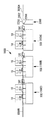
以下、本発明の実施形態を図面に基づいて説明する。図1は、本発明に係る眼鏡レンズ供給システムの全体概略図である。 Hereinafter, embodiments of the present invention will be described with reference to the drawings. FIG. 1 is an overall schematic diagram of a spectacle lens supply system according to the present invention.
眼鏡レンズ供給システム1000は、トレイTRを搬送するための少なくとも1つのベルト式のコンベアライン102を有する個別コンベアラインユニット(以下、RLCユニット)100を複数台備える。各RLCユニット100はベース101を有し、コンベアライン102に対応して少なくとも1台の眼鏡レンズ周縁加工装置10がベース101上に配置されている。加工装置10は、眼鏡レンズLEを保持するレンズチャック軸と、レンズLEの周縁を加工する周縁加工具と、を有し、入力された玉型に基づいてレンズLEと周縁加工具との相対的に移動を制御してレンズLEの周縁を加工する。この加工装置10の構成としては、特開平2004−34167号等に記載された周知のものであるので、説明は省略する。
The spectacle
トレイTRに左右一対の眼鏡レンズLE(図5参照)が収納されている。図1では、システム1000は3台のRCLユニット100(以下、3台のRCLユニット100を区別するときには、符号100A,100B,100Cを用いる)を備える。各RCLユニット100は、直列的に接続されている。すなわち、各RCLユニット100が有するコンベアライン102が直列的に接続されることにより、複数のコンベアラインユニット100が並べられたときに、コンベアライン102が実質的に1本のコンベアラインのように接続される。トレイTRは、上流側(図1上の右側)のRCLユニット100Aが有するコンベアライン102から、下流側(図1上の左側)のRCLユニット100Cが有するコンベアライン102に搬送される。
A pair of left and right eyeglass lenses LE (see FIG. 5) is stored in the tray TR. In FIG. 1, the
RCLユニット100Aの上流側には、未加工のレンズLEが入れられたトレイTRを搬入するための搬入用コンベアライン3000Aが配置されている。RCLユニット100Cの下流側には、加工済みのレンズLEが入れられたトレイTRを搬出するための搬出用コンベアライン3000Bが配置されている。また、RCLユニット100Aと搬入用コンベアライン3000Aとの間には、コンベアライン2002を有する振り分けユニット2000が配置されている。すなわち、最上流側のRCLユニット100Aより上流に振り分けユニット2000が設けられている。振り分けユニット2000は、最上流側のRCLユニット100Aのコンベアライン102にトレイTRを供給するトレイ供給ユニットとして機能し、上流側の搬入用コンベアライン3000Aから搬送されるトレイTRの移動を止めるストッパユニット2200と、識別子読み取り器(バーコードリーダ)2250と、主制御ユニット2050と、を備える。
On the upstream side of the RCL
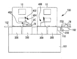
図2は、個別コンベアラインユニット100の構成を説明するための外観斜視図である。図3は、個別コンベアラインユニット100の概略的な正面図である。
FIG. 2 is an external perspective view for explaining the configuration of the individual
コンベアライン102は2本のベルト104を有し、駆動部110によって2本のベルト104が同時に移送される。コンベアライン102は、本実施形態のようにベルト式で構成される他、ローラ式等の種々の方式によって構成されても良い。コンベアライン102は、ベース101上に配置されている。ベルト104上に載せられたトレイTRは、図3上の右側から左側へ搬送される。コンベアライン102の上流側(図3の右側)には、ベルト104上のトレイTRの移動を止めるストッパユニット200と、トレイTRに添付された識別子であるバーコードBCを読み取る識別子読み取り器(バーコードリーダ)250と、が配置されている。
The
図4A及び図4Bは、ストッパユニット200の構成図であり、トレイTRの進行方向左から見た図(図3の見た図)である。ストッパユニット200は、図4A(図4B)の左右方向に延びるガイド軸203に沿って移動可能に保持された左ベース202L及び右ベース202Rを有する。左ベース202Lの上部及び右ベース202Rの上部には、それぞれストッパピン204が垂直に立てられている。左ベース202L及び右ベース202Rは、モータ208を有する駆動部206によって、互いに接近及び離れるように左右方向に移動される。駆動部206は、ラック及びピニオン等の周知の移動機構によって構成することができる。図4Aでは、2つのストッパピン204がベルト104上に載せられたトレイTRの幅WYより広く開いた状態が示されている。この場合、ベルト104の移動によってトレイTRが搬送される。図4Bでは、2つのストッパピン204がトレイTRの幅WY(トレイTRの進行方向に対して直交する方向の幅)より狭く閉じた状態が示されている。この場合、ストッパピン204がトレイTRの脚部に当り、ベルト104の移動に対してトレイTRの移動が停止される。
4A and 4B are configuration diagrams of the
図4A及び図4Bにおいて、トレイTRに添付されたバーコードBCを読み取る識別子読み取り器250が同時に示されている。トレイTRの搬送がストッパユニット200により止められた時、識別子読み取り器250によってバーコードBCが読み取られる。
4A and 4B, an
図2及び図3において、コンベアライン104上からトレイTRを移動し、加工済みレンズLEが入れられたトレイTRを再びコンベアライン104上に載せるトレイ移動ユニットとしてのトレイ昇降ユニット300が、加工装置10に対応して配置されている。トレイ昇降ユニット300は、1台の加工装置に対してコンベアライン104上から少なくとも2つのトレイTRを離脱させ、レンズ加工の待機のために設けられたそれぞれ所定の待機位置へ移動する。この例では、1台の加工装置10に対応して2台のトレイ昇降ユニット300が配置されている。図3では、RCLユニット100に対して2台の加工装置10が配置されているため、RCLユニット100に対して4台のトレイ昇降ユニット300が配置されている。
2 and 3, the tray lifting / lowering
図5は、トレイ昇降ユニット300の説明図である。コンベアライン102(ベルト104)に載せられたトレイTRは、矢印AX方向に搬送される。トレイ昇降ユニット300は、トレイTRの下端の脚部が載るプレート302を有する。プレート302は、上下移動のベース部304の上部に取り付けられている。ベース部304は、モータ306を有する上下移動機構310によって上下方向に移動される。上下移動機構310は、モータ306の回転軸に連結された送りネジを有するスライド機構、又はベルト方式のスライド機構等の周知のスライド機構によって構成される。
FIG. 5 is an explanatory diagram of the tray lifting / lowering
図5において、プレート302上の矢印AX方向(トレイTRの進行側)には、トレイTRの搬送を止める2個のストッパ部材320がコンベアライン102(2本のベルト104)を挟んで取り付けられている。2個のストッパ部材320の間隔は、トレイTRの幅WYより狭くされている。また、プレート302上には、トレイTRの幅WY方向の位置を整える接触部材322が配置されている。接触部材322はトレイTRに側面に接触される。
In FIG. 5, two
図6は、トレイ昇降ユニット300の上下移動の説明図である。図6(a)は、ベース部304が最下位の退避位置にある状態であり、ストッパ部材320の上端がコンベアライン102のベルト104の高さHBより下の位置にある。この場合、コンベアライン102(ベルト104)によって搬送されてきたトレイTRは止められず、トレイ昇降ユニット300上を通過する。
FIG. 6 is an explanatory diagram of the vertical movement of the tray lifting / lowering
コンベアライン102(ベルト104)によって搬送されてきたトレイTRを止めるときには、図6(b)のように、ベルト104の高さHBと同じ高さにプレート302が上昇される。このとき、ストッパ部材320がトレイTRに当り、トレイTRの搬送が止められる。
When stopping the tray TR conveyed by the conveyor line 102 (belt 104), the
図6(c)は、図6(b)に対してプレート302を上昇させることにより、プレート302上に載せられたトレイTRをベルト104上から離脱させた状態の図である。プレート302は、ベルト104によって搬送されてくるトレイTRの高さよりも高い所定位置に上昇される。これにより、ベルト104によって搬送されてくるトレイTRを通過させることができる。
FIG. 6C is a view showing a state in which the tray TR placed on the
再び、図2及び図3において、加工装置10とコンベアライン102との間には、レンズLEをトレイTRから取り出して加工装置10に移動し、加工装置10によって加工されたレンズLEを加工装置10から取り出し、再びトレイTRに移動するためのレンズ移動ユニットとしてのロボット400が配置されている。ロボット400は、特開2004−34167号公報に記載されたロボットハンドユニットと同様な機構により構成される。ロボット400は、ベルト104と平行に延びるレールに沿って、図3上の左右方向に移動される。ロボット400は、上下移動及び回転されるアーム402を有し、アーム402の先端にレンズLEを吸着する吸着部404が取り付けられている。トレイTR上のレンズLEは、吸着部404によって保持され、ロボット400の移動により加工装置10が有するレンズチャック軸に移動される。
2 and 3 again, between the
ロボット400は、RCLユニット100に対して少なくとも1台が設けられていれば良い。本実施形態の図2及び図3においては、RCLユニット100に2台のロボット400が配置されている。2台のロボット400により、レンズLEが効率よくトレイTRと加工装置10との間で移動される。
It is sufficient that at least one
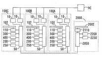
図7は、眼鏡レンズ供給システム1000の制御ブロック図である。RCLユニット100は、個別制御ユニット50を備える。個別制御ユニット50は、加工装置10、コンベアライン102の駆動部110、ストッパユニット200、識別子読み取り器250、トレイ昇降ユニット300、ロボット400に接続され、これらに制御信号を送り、これらを動作させる。
FIG. 7 is a control block diagram of the eyeglass
以上のような構成を有するRCLユニット100は、符号100A,100B,100Cで示される個別コンベアラインユニットで同じ構成とされている。このため、RCLユニット100B,100Cにおいては、個別制御ユニット50のみが図示され、他の構成は図示が略されている。
The
各RCLユニット100が有する個別制御ユニット50は、振り分けユニット2000が有する主制御ユニット2050に接続されている。振り分けユニット2000は、図4A,図4Bのストッパユニット200と同様な構成のストッパユニット2200を備える。また、トレイTRに添付されたバーコードBCを読み取る識別子読み取り器2250を備える。コンベアライン2002の駆動部2110、ストッパユニット2200、識別子読み取り器2250は、主制御ユニット2050に接続されている。また、各加工装置10はホストコンピュータHCに接続されている。ホストコンピュータHCには、作業番号に対応するレンズLEの加工条件データが記憶されている。左右一対のレンズLEの作業番号はバーコードBCに割り当てられる。作業番号が割り当てられたバーコードBCがトレイTRに添付されている。個別制御ユニット50によって取得されたバーコードBCは、加工装置10に送信される。加工装置10は、バーコードBCに対応する玉型等の加工条件データをホストコンピュータHCから取得する。加工装置10により、加工条件データに従ってレンズLEの周縁が加工される。
The
以上のような眼鏡レンズ供給システム1000において、その動作を説明する。搬入用コンベアライン3000Aには、未加工のレンズLEが入れられたトレイTRが載せられる。トレイTRは、振り分けユニット2000のコンベアライン2002に移動される。主制御ユニット2050は、ストッパユニット2200を作動させてトレイTRの移動を一旦停止し、識別子読み取り器2250によってトレイTRのバーコードを読み取る。
The operation of the spectacle
ここで、主制御ユニット2050が有するメモリには、下流側に接続されるRCLユニット100の数(図1の例では、RCLユニット100A,100B,100Cの3台である)と、各RCLユニット100が受け入れ可能なトレイTRの数(すなわち、各RCLユニット100が備えるトレイ昇降ユニット300の数)が登録されている。また、RCLユニット100の制御ユニット50は、トレイ昇降ユニット300上の待機位置にトレイTRが無く、トレイ昇降ユニット300が新規のトレイTRを受け入れ可能(搬入可能)であるときに、トレイTRを要求する要求信号を主制御ユニット2050に送信する。主制御ユニット2050は、各RCLユニット100の制御ユニット50から、トレイTRの要求信号が入力されると、識別子読み取り器2250で読み取ったバーコードを持つトレイTRの搬送先のRCLユニット100を何れにするかを決定した後、決定した搬送先のRCLユニット100の制御ユニット50に読み取ったバーコードの信号を送信する。
Here, the memory included in the
初期段階では、全てのRCLユニット100におけるトレイ昇降ユニット300がそれぞれの待機位置へトレイTRを移動可能な状態である。各制御ユニット50は、自己の担当するRCLユニット100が有するトレイ昇降ユニット300の数分の要求信号を主制御ユニット2050に送る。主制御ユニット2050は、各制御ユニット50と通信し、要求信号に基づいて搬入用コンベアライン3000A上のトレイTRを何れのRCLユニット100に搬送するかを決定する。又は、主制御ユニット2050は、搬入用コンベアライン3000Aのトレイ内のレンズを何れの加工装置10に加工させるかを決定することでも良い。そして、主制御ユニット2050は、各RCLユニット100の制御ユニット50にトレイTRに付された識別情報であるバーコードBCの信号を送信する。例えば、主制御ユニット2050は、最下流のRCLユニット100CからトレイTRを順番に搬送するように、搬送先のRCLユニット100を決定する。すなわち、主制御ユニット2050は、1番目のトレイTRをRCLユニット100Cへの振り分けに決定し、読み取り器2250で読み取ったバーコードBCの信号をユニット100Cの制御ユニット50に送信する。その後、主制御ユニット2050は、ストッパユニット2200のストッパピン204を開き、トレイTRを下流側のRCLユニット100Aに供給する。次に、制御ユニット2050は、2番目のトレイTRのバーコードBCを読み取るために、ストッパユニット2200のストッパピン204を閉じる。
In the initial stage, the tray lifting / lowering
各RCLユニット100では、上流から搬送されてきたトレイTRの識別情報であるバーコードBCを読み取り器250によって読み取り、制御ユニット50は、読み取られた識別情報と送信された識別情報とが一致する場合には、トレイ昇降ユニット300によって待機位置へトレイTRを移動させる。一方、読み取られた識別情報と送信された識別情報と一致しない場合には、制御ユニット50は、下流側のRCLユニット100へトレイTRを送る。具体的には以下である。
In each
RCLユニット100Aの制御ユニット50は、ストッパユニット200により1番目のトレイTRの移動を停止し、読み取り器250によってバーコードBCを読み取る。RCLユニット100Aの制御ユニット50は、このバーコードBCの読み取りにより、RCLユニット100Aに振り分けられたトレイTRで無いので、ストッパユニット200を開き、トレイTRを通過させる。次のRCLユニット100Bの制御ユニット50も、ストッパユニット200により1番目のトレイTRの移動を停止し、読み取り器250によってバーコードBCを読み取る。RCLユニット100Bの制御ユニット50も、RCLユニット100Aの場合と同様に、バーコードBCの読み取りにより、RCLユニット100Bに振り分けられたトレイTRで無いので、ストッパユニット200を開き、トレイTRを通過させる。
The
RCLユニット100Cの制御ユニット50は、ストッパユニット200により1番目のトレイTRの移動を停止し、読み取り器250によってバーコードBCを読み取る。そして、制御ユニット50は、バーコードBCの読み取りにより、RCLユニット100Cに割り当てられたトレイTRであると判定すると、このトレイTRのレンズLEを加工装置10に加工させるために、4台のトレイ昇降ユニット300の内の一つを動作させる。始めは、下流側の加工装置10にレンズLEを加工させるように、その加工装置10に対応する下流側のトレイ昇降ユニット300を動作させる。
The
図6(b)に示されたように、制御ユニット50は、高さHBの位置にプレート302を上昇させることにより、ストッパ部材320がベルト104より高い位置に移動され、ベルト104により搬送されてくるトレイTRが停止する。その後、さらにプレート302を上昇させる。これにより、図6(c)のように、トレイTRはプレート302に載せられ、所定の高さまの待機位置へ移動される。RCLユニット100Cの制御ユニット50は、トレイ昇降ユニット300に搭載されたトレイTRが所定の待機位置に位置すると、ロボット400を作動し、トレイTRに入れられた左右のレンズLEの一方を下流側の加工装置10に移動させる。その後、制御ユニット50は、加工装置10に加工指令信号及びバーコードBCの作業番号を送り、レンズLEの加工を開始させる。加工装置10は、バーコードBCの作業番号をホストコンピュータHCに送り、加工条件データを要求する。ホストコンピュータHCは、作業番号に対応する加工条件データを要求元の加工装置10に送信する。これにより、作業番号に対応付けられた所定の加工条件に基づいてレンズLEの周縁加工が行われる。
As shown in FIG. 6B, the
また、振り分けユニット2000の主制御ユニット2050は、RCLユニット100B及び100Aの各制御ユニット50からの要求により、2番目のトレイTRをRCLユニット100Bに振り分け、3番目のトレイTRをRCLユニット100Aに振り分ける。2番目のトレイTRはRCLユニット100Bに振り分けられているので、RCLユニット100Aの制御ユニット50は、先の説明と同様に、2番目のトレイTRのバーコードBCを読み取ると、ストッパユニット200を開放し、RCLユニット100B側に送る。RCLユニット100Bの制御ユニット50は、ストッパユニット200を作動させて2番目のトレイTRのバーコードBCを読み取ると、そのトレイTRが自己のRCLユニット100Bに振り分けられているので、RCLユニット100Cの時と同様に、下流側のトレイ昇降ユニット300を作動させる。そして、RCLユニット100Bの制御ユニット50は、ベルト104によって搬送されてきた2番目のトレイTRの移動を停止した後、プレート302を上昇させ、トレイTRを所定位置に移動させる。その後、ロボット400及び加工装置10が作動される。
Further, the
3番目のトレイTRがRCLユニット100Aのコンベアライン102に搬送されてくると、RCLユニット100Aの制御ユニット50は、ストッパユニット200及び読み取り器250の作動により、自己のユニット100Aに振り分けられたことを識別する。そして、先の説明と同様に、RCLユニット100Aの制御ユニット50は、下流側のトレイ昇降ユニット300を作動させ、トレイTRを所定位置に移動させた後、ロボット400及び加工装置10を作動させる。
When the third tray TR is conveyed to the
以後、同様に、振り分けユニット2000のコンベアライン2002に搬送されてきたトレイTRの振り分け先は、各制御ユニット50からの要求信号を受けた主制御ユニット2050により順次決定される。RCLユニット100A,100B及び100Cの各制御ユニット50は、自己のRCLユニット100に振り分けられたトレイTRで無い時には、トレイ昇降ユニット300を作動させずに、トレイTRを下流側のコンベアライン102又は搬出用コンベアライン3000Bへ送るために通過させる。制御ユニット50は、自己のRCLユニット100に振り分けられたトレイTRが搬送されてきたときには、トレイTRを待機位置へ移動可能なトレイ昇降ユニット300を決定し、そのトレイ昇降ユニット300を作動させ、トレイTRをコンベアライン102から離脱させる。
Thereafter, similarly, the distribution destination of the tray TR conveyed to the
なお、トレイTRには左右一対のレンズLEが入れられている。左右一対のレンズLEは、同一の加工装置10により加工されるように、ロボット400によりトレイTRに入れられた未加工のレンズLEが加工装置10に移動される。加工装置10は、レンズLEの加工が終了すると、その終了信号を制御ユニット50へ送る。制御ユニット50は、ロボット400を作動させ、加工装置10の加工済みレンズLEを元のトレイTRへ戻す。そして、トレイTRに左右のもう一方のレンズLEが未加工として残っていれば、ロボット400を作動し、その未加工のレンズLEを加工装置10へ移動する。制御ユニット50は、トレイTRに左右の加工済みレンズが戻されると、トレイ昇降ユニット300を作動させ、トレイTRをコンベアライン102に載せる。
The tray TR has a pair of left and right lenses LE. The unprocessed lens LE placed in the tray TR by the
また、1台の加工装置10に対して2台のトレイ昇降ユニット300が用意されている。このため、加工済みレンズLEの入ったトレイTRが次のトレイTRに交換されるのを待つことなく、2台目のトレイ昇降ユニット300によってトレイTRが待機位置へ移動され、準備されているトレイTR内のレンズLEの加工に移行することができる。すなわち、第1のトレイ昇降ユニット300によって第1待機位置へ移動されたトレイTR内のレンズLEの加工が終了した後、第1のトレイ昇降ユニット300にてトレイTRの交換中に、第2のトレイ昇降ユニット300によって第2待機位置に移動されたトレイTR内のレンズLEを加工装置10により加工させる。この加工中に、トレイTRを第1待機位置からコンベアライン102上に移動する。第1待機位置にトレイTRを受け入れ可能になると、コンベアライン102によって搬送されて来る次のトレイTR(未加工レンズが入れられたトレイ)を第1待機位置へ移動し、第1待機位置でトレイTRを待機させる。そして、第2待機位置のトレイTR内のレンズLEの加工が終了すれば、再び、第1待機位置で待機されているトレイTRのレンズLEの加工に移行する。これにより、加工装置10の稼働効率を上げることができ、レンズLEが効率よく加工される。
Further, two tray lifting / lowering
待機位置のトレイTR内の左右一対のレンズLEが加工されると、プレート302が下降され、コンベアライン102のベルト104上にトレイTRが載せられる。これにより、トレイTRが下流側の搬出用コンベアライン3000Bまで搬送される。
When the pair of left and right lenses LE in the tray TR at the standby position is processed, the
制御ユニット50は、トレイ昇降ユニット300のプレート302が最下位の退避位置に移動すると、次のトレイTRを待機位置へ受け入れる準備ができた旨の要求信号を主制御ユニット2050に送る。主制御ユニット2050は、各ユニット100の制御ユニット50からトレイTRの受け入れの要求信号を受信すると、ストッパユニット2200により搬送を停止していたトレイTRの振り分け先を順次決定する。そして、主制御ユニット2050は、ストッパユニット2200の停止を解除し、最上流側のコンベアライン102へトレイTRの供給を行う。各制御ユニット50からの要求信号が無いときには、ストッパユニット220によりトレイTRの搬送が停止したままとされ、振り分けユニット2000のコンベアライン2002及び搬入用コンベアライン3000AにトレイTRが待機することとなる。
When the
以上のように、搬入用コンベアライン3000Aと搬出用コンベアライン3000Bとの間で、複数のRCLユニット100がそれぞれ有するコンベアライン102が直列的に配置されているので、眼鏡レンズ供給システム1000の設置スペースの節約が図られる。また、複数のRCLユニット100が有するコンベアライン102を直列的に接続することにより、実質的に1本のコンベアラインとし、さらに、各RCLユニット100のトレイTRの搬送等の動作処理は、各ユニット100に設けた個別制御ユニット50により行われるため、システム1000全体を統合するための制御プログラムとして大掛かりなものが不要となる。主制御ユニット2050には、RCLユニット100の台数等の簡単な登録で済むため、ユーザの要望によってRCLユニット100の台数が変動しても、容易に対応できる。このため、ユーザの要望に対して、コストを掛けずに、経済的に有利なレンズ加工システムを構築することができる。
As described above, the
なお、最上流側に位置するRCLユニット100Aに振り分けユニット2000の機能を受け持たせ、振り分けユニット2000を省略することもできる。すなわち、RCLユニット100Aに設けられたストッパユニット200がストッパユニット2200を兼用すると共に、RCLユニット100Aに設けられた読み取り器250が読み取り器2250を兼用する。また、RCLユニット100Aの制御ユニット50が主制御ユニット2050の機能の役割を受け持つ。
The
また、図2に示すコンベアライン102は、未加工レンズが入れられたトレイTRの搬送用と、加工済みレンズが入れられたトレイTRの搬送用と、に兼用される構成とした、加工済みレンズが入れられたトレイTRを搬送するためのコンベアラインは、未加工レンズが入れられたトレイTRを搬送するコンベアラインとは別に設けられていても良い。例えば、図2において、未加工レンズが入れられたトレイTRを搬送するための第1コンベアライン102と平行に、加工済みレンズが入れられたトレイTRを搬送するための第2コンベアラインを各RCLユニット100に設ける。各RCLユニット100の第2コンベアラインも、直列的に接続されことで、実質的に1本のコンベアラインのように接続される。トレイ移動ユニット(トレイ昇降ユニット300)は、加工済みレンズが入れられたトレイTRを第2コンベアラインに載せるように制御される。これにより、加工済みレンズが入れられたトレイTRと未加工レンズが入れられたトレイTRとが、それぞれスムーズに搬送される。
Further, the
また、各個別コンベアラインユニット100(100A,10B,100C)では、読み取り器250によってトレイTRの識別情報を読み取る際には、必ずしもストッパユニット200を動作させなくても良い。読み取り器250が移動中のトレイTRのバーコードBCを読み取ることにより、搬送時間を短縮できる。
Further, in each individual conveyor line unit 100 (100A, 10B, 100C), when reading the identification information of the tray TR by the
このように、本件発は種々の変容が可能であり、技術的思想を同一にする範囲において、本件発明に含まれる。 As described above, the present invention can be variously modified, and is included in the present invention as long as the technical idea is the same.
10 加工装置
50 個別制御ユニット
100 個別コンベアラインユニット
102 コンベアライン
104 ベルト
200 ストッパユニット
250 識別子読み取り器
300 トレイ昇降ユニット
400 ロボット
1000 眼鏡レンズ供給システム
2000 振り分けユニット
2002 コンベアライン
2050 主制御ユニット
2200 ストッパユニット
2250 識別子読み取り器
DESCRIPTION OF
Claims (4)
複数のコンベアラインユニットであって、1つのコンベアラインユニットが、レンズが入ったトレイを搬送する少なくとも1つのコンベアラインと、少なくとも1台の前記加工装置と、1台の前記加工装置に対してトレイを前記コンベアラインから離脱させて待機位置まで移動させ、加工終了したレンズが入ったトレイを前記コンベアラインに載せるトレイ移動ユニットと、前記トレイ移動ユニットの作動を制御する個別制御ユニットと、を有し、複数のコンベアラインユニットが並べられたときに、前記コンベアラインが実質的に1本のコンベアラインのように接続される複数のコンベアラインユニットと、
前記各個別制御ユニットと通信可能な主制御ユニットであって、最上流のコンベアラインユニットのコンベアラインに搬送されるトレイ内のレンズを何れの前記加工装置に加工させるか、又はトレイを何れのコンベアラインユニットに搬送するか、を決める主制御ユニットと、
最上流のコンベアラインユニットが有する前記コンベアラインに搬入されるトレイの識別情報を読み取る第1読取器と、
トレイの識別情報を読み取る第2読取器であって、各コンベアラインユニットに配置された第2読取器と、を有し、
前記主制御ユニットは、決定した搬送先のコンベアラインユニットの前記個別制御ユニットへ前記第1読取器で読み取られた識別情報を送信し、
前記個別制御ユニットは、前記主制御ユニットから送信された識別情報と前記第2読取器で読み取られた識別情報とが一致する場合には、前記トレイ移動ユニットを作動させてトレイをコンベアラインから前記待機位置へ移動させ、前記主制御ユニットから送信された識別情報と前記第2読取器で読み取られた識別情報とが不一致の場合には、前記トレイ移動ユニットを作動させずにトレイを下流のコンベアラインに送ることを特徴とする眼鏡レンズ供給システム。 In a spectacle lens supply system that supplies spectacle lenses to a plurality of spectacle lens peripheral edge processing apparatuses,
A plurality of conveyor line units, wherein one conveyor line unit conveys a tray containing lenses, at least one processing apparatus, and a tray for one processing apparatus. A tray moving unit for moving the tray including the processed lens to the standby position and moving the tray to the standby position, and an individual control unit for controlling the operation of the tray moving unit. A plurality of conveyor line units that are connected like a single conveyor line when the plurality of conveyor line units are arranged;
Wherein a respective individual control units capable of communicating with the main control unit, whether to process the lens in the tray to be conveyed to the conveyor line of the conveyor line unit on the most upstream in any of the processing device, or any of the conveyor tray A main control unit that decides whether to transfer to the line unit;
A first reader for reading identification information of a tray carried into the conveyor line of the most upstream conveyor line unit;
A second reader for reading the identification information of the tray, and a second reader arranged in each conveyor line unit,
The main control unit transmits the identification information read by the first reader to the individual control unit of the determined conveyor line unit of the transport destination,
When the identification information transmitted from the main control unit matches the identification information read by the second reader, the individual control unit operates the tray moving unit to remove the tray from the conveyor line. When the identification information transmitted from the main control unit and the identification information read by the second reader do not match, the tray is moved to the downstream conveyor without operating the tray moving unit. A spectacle lens supply system characterized by being sent to a line .
複数のコンベアラインユニットであって、1つのコンベアラインユニットが、レンズが入ったトレイを搬送する少なくとも1つのコンベアラインと、少なくとも1台の前記加工装置と、1台の前記加工装置に対して少なくとも2つのトレイを前記コンベアラインから離脱させて上流から搬送されてくるトレイを通過させることができるそれぞれの待機位置へ移動させ、加工終了したレンズが入ったトレイを前記コンベアラインに載せるトレイ移動ユニットと、前記トレイ移動ユニットの作動を制御する個別制御ユニットと、を有し、複数のコンベアラインユニットが並べられたときに、前記コンベアラインが実質的に1本のコンベアラインのように接続される複数のコンベアラインユニットと、
前記各個別制御ユニットと通信可能な主制御ユニットであって、最上流のコンベアラインユニットのコンベアラインに搬送されるトレイ内のレンズを何れの前記加工装置に加工させるか、又はトレイを何れのコンベアラインユニットに搬送するかの振り分けを決め、最上流のコンベアラインへトレイを供給する主制御ユニットと、を備え、
前記各個別制御ユニットは、自己のコンベアラインユニットに振り分けられたトレイが搬送されてきたときに前記トレイ移動ユニットを作動させ、トレイを前記コンベアラインから前記待機位置へ移動させる構成であることを特徴とする眼鏡レンズ供給システム。 In a spectacle lens supply system that supplies spectacle lenses to a plurality of spectacle lens peripheral edge processing apparatuses,
A plurality of conveyor line units, wherein one conveyor line unit is at least one conveyor line for conveying a tray containing lenses, at least one processing apparatus, and at least one processing apparatus. A tray moving unit that separates the two trays from the conveyor line and moves the trays to the respective standby positions where the trays conveyed from the upstream can pass, and places the trays with the processed lenses on the conveyor line; A plurality of individual control units that control the operation of the tray moving unit, and when the plurality of conveyor line units are arranged, the plurality of conveyor lines are connected substantially like one conveyor line. Conveyor line unit
A main control unit capable of communicating with each of the individual control units, which causes the lens in the tray conveyed to the conveyor line of the most upstream conveyor line unit to be processed by any of the processing devices, or which conveyor the tray is A main control unit that determines whether to transfer to the line unit and supplies the tray to the most upstream conveyor line,
Each of the individual control units is configured to operate the tray moving unit when the tray distributed to its own conveyor line unit is conveyed and to move the tray from the conveyor line to the standby position. Eyeglass lens supply system.
最上流のコンベアラインユニットが有する前記コンベアラインに搬入されるトレイの識別情報を読み取る第1読取器と、
トレイの識別情報を読み取る第2読取器であって、各コンベアラインユニットに配置された第2読取器と、を有し、
前記主制御ユニットは、決定した搬送先のコンベアラインユニットの前記個別制御ユニットへ前記第1読取器で読み取られた識別情報を送信し、
各コンベアラインユニットの前記個別制御ユニットは、前記主制御ユニットから送信された識別情報と前記第2読取器で読み取られた識別情報とが一致する場合には、前記トレイ移動ユニットを作動させ、トレイをコンベアラインから離脱させて前記待機位置へ順次移動させ、前記主制御ユニットから送信された識別情報と前記第2読取器で読み取られた識別情報とが一致しない場合には、前記トレイ移動ユニットを作動させず、トレイを下流のコンベアラインに送ることを特徴とする眼鏡レンズ供給システム。 In the spectacle lens supply system according to claim 3 ,
A first reader for reading identification information of a tray carried into the conveyor line of the most upstream conveyor line unit;
A second reader for reading the identification information of the tray, and a second reader arranged in each conveyor line unit,
The main control unit transmits the identification information read by the first reader to the individual control unit of the determined conveyor line unit of the transport destination,
The individual control unit of each conveyor line unit operates the tray moving unit when the identification information transmitted from the main control unit matches the identification information read by the second reader, When the identification information transmitted from the main control unit and the identification information read by the second reader do not match, the tray moving unit is moved away from the conveyor line and sequentially moved to the standby position. A spectacle lens supply system that feeds a tray to a downstream conveyor line without being operated.
Priority Applications (3)
| Application Number | Priority Date | Filing Date | Title |
|---|---|---|---|
| JP2012027507A JP5987338B2 (en) | 2011-02-16 | 2012-02-10 | Eyeglass lens supply system |
| US13/397,046 US9031682B2 (en) | 2011-02-16 | 2012-02-15 | Eyeglass lens supplying system |
| EP12001021.0A EP2489468B1 (en) | 2011-02-16 | 2012-02-16 | Eyeglass lens supplying system |
Applications Claiming Priority (3)
| Application Number | Priority Date | Filing Date | Title |
|---|---|---|---|
| JP2011031459 | 2011-02-16 | ||
| JP2011031459 | 2011-02-16 | ||
| JP2012027507A JP5987338B2 (en) | 2011-02-16 | 2012-02-10 | Eyeglass lens supply system |
Publications (3)
| Publication Number | Publication Date |
|---|---|
| JP2012183633A JP2012183633A (en) | 2012-09-27 |
| JP2012183633A5 JP2012183633A5 (en) | 2015-03-19 |
| JP5987338B2 true JP5987338B2 (en) | 2016-09-07 |
Family
ID=45655057
Family Applications (1)
| Application Number | Title | Priority Date | Filing Date |
|---|---|---|---|
| JP2012027507A Active JP5987338B2 (en) | 2011-02-16 | 2012-02-10 | Eyeglass lens supply system |
Country Status (3)
| Country | Link |
|---|---|
| US (1) | US9031682B2 (en) |
| EP (1) | EP2489468B1 (en) |
| JP (1) | JP5987338B2 (en) |
Families Citing this family (8)
| Publication number | Priority date | Publication date | Assignee | Title |
|---|---|---|---|---|
| DE202012011690U1 (en) | 2012-03-09 | 2013-03-13 | Schneider Gmbh & Co. Kg | Plant for processing optical lenses |
| JP6225430B2 (en) * | 2013-02-09 | 2017-11-08 | 株式会社ニデック | Eyeglass lens peripheral processing system and spectacle lens peripheral processing program |
| DE102015015040A1 (en) * | 2015-11-12 | 2017-05-18 | Schneider Gmbh & Co. Kg | Method, installation and system for processing optical lenses |
| DE102016007837A1 (en) | 2016-05-25 | 2017-11-30 | Schneider Gmbh & Co. Kg | Method and system for processing optical lenses |
| EP3517284A1 (en) * | 2018-01-26 | 2019-07-31 | Essilor International | System and method for automated ophthalmic lens manufacturing |
| DE102019114439B4 (en) * | 2019-05-29 | 2021-03-25 | TGA Technische Gebäudeausrüstung Meiningen GmbH | Modular automation system and method for its operation |
| KR20210040265A (en) | 2019-10-03 | 2021-04-13 | 가부시키가이샤 니데크 | Eyeglass frame manufacturing system and recording medium |
| CN112059818A (en) * | 2020-08-19 | 2020-12-11 | 万盟特自动化(上海)有限公司 | Large casting polishing equipment |
Family Cites Families (30)
| Publication number | Priority date | Publication date | Assignee | Title |
|---|---|---|---|---|
| US4662119A (en) | 1984-07-25 | 1987-05-05 | Haruchika Precision Company, Ltd. | Automatic lens grinding apparatus |
| US5555504A (en) * | 1994-06-10 | 1996-09-10 | Johnson & Johnson Vision Products, Inc. | Production line tracking and quality control system |
| US5578331A (en) * | 1994-06-10 | 1996-11-26 | Vision Products, Inc. | Automated apparatus for preparing contact lenses for inspection and packaging |
| US5649410A (en) * | 1994-06-10 | 1997-07-22 | Johnson & Johnson Vision Products, Inc. | Post-hydration method and apparatus for transporting, inspecting and packaging contact lenses |
| JP3630888B2 (en) | 1996-10-31 | 2005-03-23 | 株式会社ニデック | Lens transport device, spectacle lens fixed cup for transporting spectacle lens, and lens transport method |
| JP3830617B2 (en) * | 1997-05-13 | 2006-10-04 | Hoya株式会社 | Method and system for separating and setting the transfer pallet on the free flow conveyor |
| DE19815728C2 (en) | 1998-04-08 | 2000-05-18 | Wernicke & Co Gmbh | System for shaping the edges of spectacle lenses |
| JP3778707B2 (en) | 1998-09-29 | 2006-05-24 | 株式会社ニデック | Eyeglass lens processing equipment |
| US6609041B1 (en) * | 1999-05-05 | 2003-08-19 | Johnson & Johnson Vision Care, Inc. | Method and system for SKU tracking and changeover |
| JP2007268706A (en) | 2000-02-22 | 2007-10-18 | Hoya Corp | Layout block device for lens |
| JP4414403B2 (en) | 2000-02-22 | 2010-02-10 | Hoya株式会社 | Lens layout block device and method for manufacturing spectacle lens |
| JP2002036083A (en) | 2000-07-24 | 2002-02-05 | Hoya Corp | Layout, block, and working device for eyeglass lens |
| US7051290B2 (en) * | 2001-02-20 | 2006-05-23 | Q2100, Inc. | Graphical interface for receiving eyeglass prescription information |
| US7139636B2 (en) * | 2001-02-20 | 2006-11-21 | Q2100, Inc. | System for preparing eyeglass lenses with bar code reader |
| US6790024B2 (en) * | 2001-02-20 | 2004-09-14 | Q2100, Inc. | Apparatus for preparing an eyeglass lens having multiple conveyor systems |
| CN100430185C (en) | 2001-07-25 | 2008-11-05 | 精工爱普生株式会社 | Polishing jig, conveyor tray, conveying method and conveying device |
| US6464484B1 (en) * | 2002-03-30 | 2002-10-15 | Q2100, Inc. | Apparatus and system for the production of plastic lenses |
| JP2004034166A (en) | 2002-06-28 | 2004-02-05 | Nidek Co Ltd | Lens machining system |
| JP2004034167A (en) | 2002-06-28 | 2004-02-05 | Nidek Co Ltd | Grinding fluid removing apparatus and lens machining system |
| JP4138569B2 (en) * | 2003-04-30 | 2008-08-27 | 株式会社ニデック | Lens processing system |
| US7448938B2 (en) * | 2003-11-05 | 2008-11-11 | Hoya Corporation | Method for supplying spectacle lens |
| US7090559B2 (en) * | 2003-11-19 | 2006-08-15 | Ait Industries Co. | Ophthalmic lens manufacturing system |
| JP2005202162A (en) * | 2004-01-15 | 2005-07-28 | Nidek Co Ltd | Lens stock apparatus and lens machining system having the same |
| DE102004029665A1 (en) | 2004-03-30 | 2005-10-27 | Continental Teves Ag & Co. Ohg | Modular transfer system for workpieces |
| JP4446934B2 (en) * | 2005-06-30 | 2010-04-07 | 株式会社ニデック | Eyeglass lens processing equipment |
| US7785092B2 (en) * | 2005-08-09 | 2010-08-31 | Coopervision International Holding Company, Lp | Systems and methods for producing contact lenses from a polymerizable composition |
| JP4853099B2 (en) * | 2006-05-09 | 2012-01-11 | 株式会社デンソー | Production system |
| MY147130A (en) * | 2007-05-18 | 2012-10-31 | Coopervision Int Holding Co Lp | Thermal curing methods and systems for forming contact lenses |
| US20100136227A1 (en) * | 2008-09-10 | 2010-06-03 | The Walman Optical Company | Lens handling in automated lens coating systems |
| DE102008041945B4 (en) * | 2008-09-10 | 2010-08-05 | Carl Zeiss Vision Gmbh | Transport container system for prescription eyeglass lens production and method for transporting spectacle lenses and / or spectacle lens blanks |
-
2012
- 2012-02-10 JP JP2012027507A patent/JP5987338B2/en active Active
- 2012-02-15 US US13/397,046 patent/US9031682B2/en active Active
- 2012-02-16 EP EP12001021.0A patent/EP2489468B1/en active Active
Also Published As
| Publication number | Publication date |
|---|---|
| JP2012183633A (en) | 2012-09-27 |
| US20120209416A1 (en) | 2012-08-16 |
| EP2489468A3 (en) | 2014-08-20 |
| EP2489468B1 (en) | 2017-04-12 |
| US9031682B2 (en) | 2015-05-12 |
| EP2489468A2 (en) | 2012-08-22 |
Similar Documents
| Publication | Publication Date | Title |
|---|---|---|
| JP5987338B2 (en) | Eyeglass lens supply system | |
| KR101763268B1 (en) | Transfer system | |
| KR101794700B1 (en) | Automatic Selecting Apparatus for FPCB | |
| US20160163576A1 (en) | Processing object transport system, and substrate inspection system | |
| JP5912764B2 (en) | Transport unit and transport device | |
| JP2012183633A5 (en) | ||
| KR20180006787A (en) | Wire bonder distribution system and magazine transferring method thereof | |
| JPH06177244A (en) | Dicing system | |
| JP6104429B2 (en) | Transport system | |
| JP6411852B2 (en) | Conveying device, conveying system, and conveying method | |
| JP6625857B2 (en) | Wafer processing method | |
| WO2018147016A1 (en) | Conveyance system | |
| JP4499661B2 (en) | Substrate transfer method and apparatus | |
| JP5015931B2 (en) | Device for transporting workpiece supports | |
| JP2011091288A (en) | Component mounting apparatus, and component mounting method | |
| KR101747756B1 (en) | Semiconductor manufacturing system and controlling method thereof | |
| KR20180020011A (en) | Dual substrate sorting apparatus and method | |
| CN110312415B (en) | Substrate conveying device and electronic component mounting device | |
| JP2009530212A (en) | Linear machine for processing portable object and method for processing portable object | |
| KR102471189B1 (en) | Apparatus for transferring substrates | |
| TWM630720U (en) | Feeding system and board separating equipment | |
| JP2013153226A (en) | Board transportation method in component mounting system | |
| KR101333522B1 (en) | Device for loading continuously in automatic manner | |
| JP2015038930A (en) | Component mount method and component mounting apparatus | |
| JP2854454B2 (en) | Plate transport device |
Legal Events
| Date | Code | Title | Description |
|---|---|---|---|
| A521 | Request for written amendment filed |
Free format text: JAPANESE INTERMEDIATE CODE: A523 Effective date: 20150130 |
|
| A621 | Written request for application examination |
Free format text: JAPANESE INTERMEDIATE CODE: A621 Effective date: 20150130 |
|
| A977 | Report on retrieval |
Free format text: JAPANESE INTERMEDIATE CODE: A971007 Effective date: 20151127 |
|
| A131 | Notification of reasons for refusal |
Free format text: JAPANESE INTERMEDIATE CODE: A131 Effective date: 20151222 |
|
| A521 | Request for written amendment filed |
Free format text: JAPANESE INTERMEDIATE CODE: A523 Effective date: 20160222 |
|
| TRDD | Decision of grant or rejection written | ||
| A01 | Written decision to grant a patent or to grant a registration (utility model) |
Free format text: JAPANESE INTERMEDIATE CODE: A01 Effective date: 20160712 |
|
| A61 | First payment of annual fees (during grant procedure) |
Free format text: JAPANESE INTERMEDIATE CODE: A61 Effective date: 20160725 |
|
| R150 | Certificate of patent or registration of utility model |
Ref document number: 5987338 Country of ref document: JP Free format text: JAPANESE INTERMEDIATE CODE: R150 |
|
| R250 | Receipt of annual fees |
Free format text: JAPANESE INTERMEDIATE CODE: R250 |
|
| R250 | Receipt of annual fees |
Free format text: JAPANESE INTERMEDIATE CODE: R250 |
|
| R250 | Receipt of annual fees |
Free format text: JAPANESE INTERMEDIATE CODE: R250 |
|
| R250 | Receipt of annual fees |
Free format text: JAPANESE INTERMEDIATE CODE: R250 |
|
| R250 | Receipt of annual fees |
Free format text: JAPANESE INTERMEDIATE CODE: R250 |