JP5985508B2 - Turbine engine starting method - Google Patents
Turbine engine starting method Download PDFInfo
- Publication number
- JP5985508B2 JP5985508B2 JP2013548874A JP2013548874A JP5985508B2 JP 5985508 B2 JP5985508 B2 JP 5985508B2 JP 2013548874 A JP2013548874 A JP 2013548874A JP 2013548874 A JP2013548874 A JP 2013548874A JP 5985508 B2 JP5985508 B2 JP 5985508B2
- Authority
- JP
- Japan
- Prior art keywords
- starting
- combustion chamber
- ignition
- shaft
- fuel
- Prior art date
- Legal status (The legal status is an assumption and is not a legal conclusion. Google has not performed a legal analysis and makes no representation as to the accuracy of the status listed.)
- Expired - Fee Related
Links
Images


Classifications
-
- F—MECHANICAL ENGINEERING; LIGHTING; HEATING; WEAPONS; BLASTING
- F02—COMBUSTION ENGINES; HOT-GAS OR COMBUSTION-PRODUCT ENGINE PLANTS
- F02C—GAS-TURBINE PLANTS; AIR INTAKES FOR JET-PROPULSION PLANTS; CONTROLLING FUEL SUPPLY IN AIR-BREATHING JET-PROPULSION PLANTS
- F02C7/00—Features, components parts, details or accessories, not provided for in, or of interest apart form groups F02C1/00 - F02C6/00; Air intakes for jet-propulsion plants
- F02C7/26—Starting; Ignition
- F02C7/268—Starting drives for the rotor, acting directly on the rotor of the gas turbine to be started
- F02C7/27—Fluid drives
-
- F—MECHANICAL ENGINEERING; LIGHTING; HEATING; WEAPONS; BLASTING
- F01—MACHINES OR ENGINES IN GENERAL; ENGINE PLANTS IN GENERAL; STEAM ENGINES
- F01D—NON-POSITIVE DISPLACEMENT MACHINES OR ENGINES, e.g. STEAM TURBINES
- F01D19/00—Starting of machines or engines; Regulating, controlling, or safety means in connection therewith
-
- F—MECHANICAL ENGINEERING; LIGHTING; HEATING; WEAPONS; BLASTING
- F02—COMBUSTION ENGINES; HOT-GAS OR COMBUSTION-PRODUCT ENGINE PLANTS
- F02C—GAS-TURBINE PLANTS; AIR INTAKES FOR JET-PROPULSION PLANTS; CONTROLLING FUEL SUPPLY IN AIR-BREATHING JET-PROPULSION PLANTS
- F02C7/00—Features, components parts, details or accessories, not provided for in, or of interest apart form groups F02C1/00 - F02C6/00; Air intakes for jet-propulsion plants
- F02C7/26—Starting; Ignition
- F02C7/262—Restarting after flame-out
-
- F—MECHANICAL ENGINEERING; LIGHTING; HEATING; WEAPONS; BLASTING
- F05—INDEXING SCHEMES RELATING TO ENGINES OR PUMPS IN VARIOUS SUBCLASSES OF CLASSES F01-F04
- F05D—INDEXING SCHEME FOR ASPECTS RELATING TO NON-POSITIVE-DISPLACEMENT MACHINES OR ENGINES, GAS-TURBINES OR JET-PROPULSION PLANTS
- F05D2220/00—Application
- F05D2220/30—Application in turbines
- F05D2220/32—Application in turbines in gas turbines
- F05D2220/329—Application in turbines in gas turbines in helicopters
-
- F—MECHANICAL ENGINEERING; LIGHTING; HEATING; WEAPONS; BLASTING
- F05—INDEXING SCHEMES RELATING TO ENGINES OR PUMPS IN VARIOUS SUBCLASSES OF CLASSES F01-F04
- F05D—INDEXING SCHEME FOR ASPECTS RELATING TO NON-POSITIVE-DISPLACEMENT MACHINES OR ENGINES, GAS-TURBINES OR JET-PROPULSION PLANTS
- F05D2260/00—Function
- F05D2260/85—Starting
-
- F—MECHANICAL ENGINEERING; LIGHTING; HEATING; WEAPONS; BLASTING
- F05—INDEXING SCHEMES RELATING TO ENGINES OR PUMPS IN VARIOUS SUBCLASSES OF CLASSES F01-F04
- F05D—INDEXING SCHEME FOR ASPECTS RELATING TO NON-POSITIVE-DISPLACEMENT MACHINES OR ENGINES, GAS-TURBINES OR JET-PROPULSION PLANTS
- F05D2260/00—Function
- F05D2260/99—Ignition, e.g. ignition by warming up of fuel or oxidizer in a resonant acoustic cavity
Description
本発明は、タービンエンジンの分野に関し、特に、航空機のターボシャフトエンジンの分野に関する。 The present invention relates to the field of turbine engines, and in particular to the field of aircraft turboshaft engines.
より詳細には、本発明は、
点火装置と少なくとも1つの主噴射装置とを有する燃焼室であって、出口を有する燃焼室と、
燃焼室に圧縮空気を供給するために燃焼室の上流側に配置された圧縮機ホイールに接続されるシャフトと、
前記シャフトに接続される始動装置と
を備えるタービンエンジンの始動方法であって、
シャフトを回転駆動するために始動装置が作動される第1の始動ステップと、
燃焼室に燃料が噴射され、点火装置が作動される第1の点火ステップと
を含む始動方法に関する。このステップの時に、主噴射装置に燃料が供給されるのが好ましい。
More particularly, the present invention provides:
A combustion chamber having an ignition device and at least one main injection device, the combustion chamber having an outlet;
A shaft connected to a compressor wheel disposed upstream of the combustion chamber for supplying compressed air to the combustion chamber;
A starting method for a turbine engine comprising: a starting device connected to the shaft;
A first starting step in which a starting device is actuated to drive the shaft in rotation;
And a first ignition step in which fuel is injected into a combustion chamber and an ignition device is operated. Preferably, fuel is supplied to the main injector during this step.
通常、第1の始動ステップの終わりに、点火装置(通常は、スパークプラグ)によって点火された後に燃焼室内で安定した燃焼が行われることにより、タービンエンジンを始動させることができる。 Usually, at the end of the first starting step, the turbine engine can be started by causing stable combustion in the combustion chamber after ignition by an igniter (usually a spark plug).
タービンエンジンが始動すると、すなわち、高圧タービンが燃焼室からの燃焼ガス流により回転駆動されてシャフトが自律回転できるようになると、点火装置と始動装置とはオフになる。 When the turbine engine starts, that is, when the high-pressure turbine is rotationally driven by the combustion gas flow from the combustion chamber and the shaft can rotate autonomously, the ignition device and the starter are turned off.
しかし、始動を試みた時に、例えば、始動装置によるトルクが高すぎる、または燃料噴射圧力が達成されると同時に、始動装置によってすでに駆動されているシャフトの回転速度が速すぎる場合には、タービンエンジンが機能しない場合がある。これは、例えば、燃料供給回路内に空気が存在するために発生する場合がある、または外部温度が非常に低い時に発生する場合がある。 However, when a start is attempted, for example, if the torque by the starter is too high or if the fuel injection pressure is achieved and at the same time the rotational speed of the shaft already driven by the starter is too high, the turbine engine May not work. This may occur, for example, due to the presence of air in the fuel supply circuit, or may occur when the external temperature is very low.
本発明の目的は、より信頼性があり、さらに始動が実行可能な範囲を、例えば、高い高度または非常に低い温度での始動のような厳しいウィンドウまで拡大することができるタービンエンジンの始動方法を提供することである。 It is an object of the present invention to provide a method for starting a turbine engine that is more reliable and can extend the feasible range of starting to a severe window, such as starting at high altitudes or very low temperatures. Is to provide.
本発明は、上述の目的を、本発明の方法が、シャフトが第1の所定の速度値に達した時に燃焼が適切に行われない場合に実行される再試行ステップであって、
始動装置と点火装置が停止される停止ステップと、
燃料が燃焼室に噴射され、点火装置が作動される第2の点火ステップであって、シャフトの回転速度が第2の所定の速度値に達した時に実行される第2の点火ステップと、
シャフトを回転駆動するために始動装置が再度作動される第2の始動ステップと
を含む再試行ステップをさらに含むことにより達成する。
The present invention has the above-mentioned object as a retry step that is performed if the method of the present invention is not properly combusted when the shaft reaches a first predetermined speed value,
A stop step in which the starting device and the ignition device are stopped;
A second ignition step in which fuel is injected into the combustion chamber and the ignition device is operated, the second ignition step being executed when the rotational speed of the shaft reaches a second predetermined speed value;
This is accomplished by further including a retry step including a second start step in which the starter is again actuated to drive the shaft in rotation.
したがって、再試行ステップは、タービンエンジンの点火が失敗した場合に実行される。 Thus, the retry step is performed when the turbine engine ignition fails.
点火ステップおよび始動ステップの時に、燃料は、主噴射装置によって噴射されるか、もしあれば、主噴射装置と同様に始動噴射装置によって噴射される。始動噴射装置は、主噴射装置と別個の装置としてもよいし、主噴射装置に組み込まれてもよい(2回路式主噴射装置)。 During the ignition and start steps, fuel is injected by the main injector or, if any, by the start injector as well as the main injector. The starting injection device may be a separate device from the main injection device, or may be incorporated in the main injection device (two-circuit main injection device).
タービンエンジンの点火不良は、本明細書では、シャフトが第1の所定の速度値に達した時に十分な熱を発生させる燃焼が行われていない状態として定義される。このような状況下では、シャフトの速度は、非常に遅い速度値と、第1の所定速度値と第2の所定の速度値との間にある他の速度値との間の値として定義された「始動」ウィンドウとして周知の速度ウィンドウ外にある。 Turbine engine ignition failure is defined herein as a condition in which there is no combustion that generates sufficient heat when the shaft reaches a first predetermined speed value. Under such circumstances, the shaft speed is defined as a value between a very slow speed value and another speed value between the first predetermined speed value and the second predetermined speed value. It is outside the speed window known as the “start” window.
また、第2の点火ステップと第2の始動ステップは、減速ステップの後に実行される。 The second ignition step and the second start step are executed after the deceleration step.
したがって、再試行ステップは、
タービンエンジンの第1の点火が失敗した場合にタービンエンジンを新たに始動させるステップであることがわかる。このステップは、有利には、始動装置が停止された結果、シャフトの回転速度が減速し、再度点火ウィンドウに入るまで十分に減速した時に実行される。
Therefore, the retry step is
It can be seen that this is the step of starting the turbine engine anew if the first ignition of the turbine engine fails. This step is advantageously performed when the speed of rotation of the shaft is reduced as a result of the starter being stopped and is sufficiently reduced until it enters the ignition window again.
さらに、本発明により、シャフトの回転速度が点火ウィンドウ内でより長い時間維持されるので、始動の機会を最大にすることができる。 Furthermore, the present invention maximizes the opportunity for starting because the rotational speed of the shaft is maintained for a longer time within the ignition window.
本発明では、シャフトの回転速度は、第2の点火ステップを実行する前に始動装置を停止することによって点火ウィンドウに戻される。すなわち、シャフトは停止ステップ時に減速する。 In the present invention, the rotational speed of the shaft is returned to the ignition window by stopping the starter before performing the second ignition step. That is, the shaft is decelerated during the stop step.
燃料の噴射は、停止ステップ時に停止されるのが好ましいが、これに限定されない。 The fuel injection is preferably stopped during the stop step, but is not limited thereto.
変形形態では、第2の点火ステップと第2の始動ステップは同時に実行されてもよい。 In a variant, the second ignition step and the second starting step may be performed simultaneously.
好ましくは、限定的ではないが、ヘリコプタ式航空機のターボシャフトエンジンの場合、第1の所定の速度値は、最大エンジン速度の15%〜20%の範囲内にあり、第2の所定の速度値は、最大エンジン速度の10%〜15%の範囲内にある。 Preferably, but not exclusively, in the case of a helicopter aircraft turboshaft engine, the first predetermined speed value is in the range of 15% to 20% of the maximum engine speed, and the second predetermined speed value. Is in the range of 10% to 15% of the maximum engine speed.
有利には、停止ステップは、シャフトが第1の所定の速度値に達した時に測定された燃焼室の出口の温度が第1の所定の温度値未満である場合に実行される。 Advantageously, the stopping step is performed when the temperature at the combustion chamber outlet, measured when the shaft reaches a first predetermined speed value, is less than the first predetermined temperature value.
燃焼室の出口で測定される温度は、燃焼が正確に行われているか(すなわち、主噴射装置(複数可)が正確に点火されているか否か、および/または始動噴射装置(複数可)が正確に点火されているか否か)を決定するという観点から有利な指標となる。 The temperature measured at the exit of the combustion chamber is such that the combustion is accurate (ie, whether the main injector (s) are correctly ignited and / or the starting injector (s)). This is an advantageous index from the viewpoint of determining whether or not the ignition is accurate.
したがって、第1の所定の温度値は、温度が燃焼室の出口で第1の所定の温度値より高い温度が測定された場合に、燃焼室は非常に高い確率で正確に点火されていることを示すように選択される。 Therefore, the first predetermined temperature value is that the combustion chamber is accurately ignited with a very high probability when a temperature is measured at the outlet of the combustion chamber that is higher than the first predetermined temperature value. Is selected.
逆に、第1の所定の温度値未満の温度が測定された場合、非常に高い確率で燃焼室が点火されていないことになる。 Conversely, if a temperature below the first predetermined temperature value is measured, the combustion chamber is not ignited with a very high probability.
好ましくは、限定的ではないが、第1の所定温度値は、150℃〜250℃である。 Preferably, but not exclusively, the first predetermined temperature value is 150 ° C to 250 ° C.
変形形態では、第1の所定の温度値は、第1の点火ステップの開始時のタービンエンジンの温度から決定される。例えば、第1の所定の温度値は、第1の始動の試みの開始時のタービンエンジンの温度より高い約100℃に相当する温度にしてもよい。 In a variant, the first predetermined temperature value is determined from the temperature of the turbine engine at the start of the first ignition step. For example, the first predetermined temperature value may be a temperature corresponding to about 100 ° C. that is higher than the temperature of the turbine engine at the start of the first start attempt.
したがって、第1の点火ステップ時に燃焼室の点火不良が生じ、この不良が燃焼室の出口の温度を測定することで検出された場合、始動装置と点火装置は、シャフトの速度が第2の所定の速度値未満になるまで停止され、その後、第2の点火ステップが実行される。 Accordingly, if a combustion chamber ignition failure occurs during the first ignition step and this failure is detected by measuring the temperature of the combustion chamber outlet, the starter and the ignition device have a shaft speed of a second predetermined value. Is stopped until the speed value is less than the speed value, and then the second ignition step is performed.
有利には、第2の始動ステップは、第2の点火ステップから一定の時間が経過した後に実行される。 Advantageously, the second start-up step is performed after a certain time has elapsed since the second ignition step.
利点としては、シャフトの回転速度を再度上昇させる前に主噴射装置(または、もしあれば始動噴射装置)が正確に点火されるのを確認することで、燃焼室が点火されずに点火ウィンドウを再び出るリスクを抑えることができるということである。 The advantage is that by confirming that the main injector (or the starter injector, if any) is ignited correctly before the shaft speed is increased again, the combustion window is not ignited and the ignition window is It means that the risk of coming out again can be suppressed.
好ましくは、第2の始動ステップは、燃焼室の出口の温度が第2の所定の温度値に達した時に実行される。 Preferably, the second starting step is performed when the temperature at the outlet of the combustion chamber reaches a second predetermined temperature value.
この検査により、主噴射装置および/または始動噴射装置が正確に点火されたか確認することができる。 By this inspection, it can be confirmed whether the main injection device and / or the starting injection device are correctly ignited.
この第2の所定の温度値は、第1の所定の温度値未満である。第2の所定の温度値は、好ましくは、50℃〜150℃である。 The second predetermined temperature value is less than the first predetermined temperature value. The second predetermined temperature value is preferably 50 ° C to 150 ° C.
変形形態では、第2の所定の温度値は、第2の点火ステップの開始時のタービンエンジンの温度から決定される。例えば、第2の所定の温度値は、第2の点火ステップの開始時のタービンエンジンの温度より高い約25℃に相当する温度にしてもよい。 In a variant, the second predetermined temperature value is determined from the temperature of the turbine engine at the start of the second ignition step. For example, the second predetermined temperature value may be a temperature corresponding to about 25 ° C., which is higher than the temperature of the turbine engine at the start of the second ignition step.
有利には、第2の始動ステップは、第2の点火ステップと同時に実行される。 Advantageously, the second starting step is performed simultaneously with the second ignition step.
第2の始動ステップ後、シャフトの速度は再度上昇し、本発明では、シャフトが第1の所定の速度値に再度達した時に燃焼室内で燃焼がまだ正確に行われていない場合、上述の再試行ステップが繰り返される。 After the second start-up step, the speed of the shaft increases again, and in the present invention, if the combustion has not yet been accurately performed in the combustion chamber when the shaft reaches the first predetermined speed value again, The trial step is repeated.
有利には、始動装置と点火装置は、シャフトが第3の所定の速度値に達した後に停止される。 Advantageously, the starting device and the ignition device are stopped after the shaft has reached a third predetermined speed value.
第2の所定の速度値より高い第3の所定の速度値は、シャフトの速度が第3の所定の速度値に達した時に、確実にタービンエンジンが自律的に動作するように選択される。 A third predetermined speed value that is higher than the second predetermined speed value is selected to ensure that the turbine engine operates autonomously when the shaft speed reaches the third predetermined speed value.
この時点で、燃料は、主噴射装置のみによって噴霧される。 At this point, fuel is sprayed only by the main injector.
好ましくは、第3の所定の回転速度値は、最大エンジン速度の30%〜65%である。 Preferably, the third predetermined rotational speed value is 30% to 65% of the maximum engine speed.
変形形態では、再試行ステップは、連続して点火不良が発生した場合に複数回繰り返されてもよい。しかし、この再試行の回数を制限するのが有利であり、適切な制御手段によって自動的に行われるのが好ましい。非限定的な例として、ヘリコプタエンジンの場合、始動を試みるのは2回のみ(第1の始動ステップと再試行ステップ)とするのが好ましいが、これに限らない。 In a variant, the retry step may be repeated a plurality of times when ignition failures occur continuously. However, it is advantageous to limit the number of retries and is preferably done automatically by appropriate control means. As a non-limiting example, in the case of a helicopter engine, it is preferable to try to start only twice (a first start step and a retry step), but this is not a limitation.
好適な実施形態では、燃焼室はさらに始動噴射装置を含み、始動噴射装置は、主噴射装置(複数可)とは別個のものであるのが好ましい。第1の点火ステップ時に、始動噴射装置は、燃料を燃焼室に噴射する。 In a preferred embodiment, the combustion chamber further includes a starter injector, which is preferably separate from the main injector (s). During the first ignition step, the starter injector injects fuel into the combustion chamber.
したがって、この実施形態では、このようなタービンエンジン(例えば、ヘリコプタターボシャフトエンジンとしてよいが、これに限らない)は、始動噴射装置と呼ばれる1つまたは複数の専用噴射装置を利用して始動されることがわかる。タービンエンジンを始動させるために、これらの噴射装置からの火炎が主噴射装置(複数可)で構成される主噴射システムに連続して伝播される。 Thus, in this embodiment, such a turbine engine (e.g., but not limited to a helicopter turboshaft engine) is started utilizing one or more dedicated injectors called starter injectors. I understand that. In order to start the turbine engine, flames from these injectors are continuously propagated to the main injection system comprised of the main injector (s).
この実施形態では、始動噴射装置は、停止ステップおよび再試行ステップの時に停止されるのが好ましいが、これに限らない。 In this embodiment, the starting injector is preferably stopped during the stop step and the retry step, but is not limited thereto.
さらに、この実施形態では、始動噴射装置は、第2の点火ステップ時に燃焼室に燃料を噴射する。 Furthermore, in this embodiment, the starting injector injects fuel into the combustion chamber during the second ignition step.
本発明はさらに、コンピュータプログラムがコンピュータ上で実行される時に本発明の始動方法のステップを実行するための命令を含むコンピュータプログラムに関する。本発明はさらに、上述のコンピュータプログラムが記憶されたコンピュータ可読記憶媒体に関する。 The invention further relates to a computer program comprising instructions for executing the steps of the starting method of the invention when the computer program is executed on a computer. The present invention further relates to a computer-readable storage medium storing the above-described computer program.
最後に、本発明は、本発明の記憶媒体を含むタービンエンジンコンピュータを提供する。 Finally, the present invention provides a turbine engine computer including the storage medium of the present invention.
以下の非限定的な例として挙げられた実施形態の説明を読めば、本発明はより十分に理解され、本発明の利点はより明らかになるであろう。添付図面を参照しながら説明する。 The invention will be more fully understood and the advantages of the invention will become more apparent after reading the following description of the embodiments given as non-limiting examples. This will be described with reference to the accompanying drawings.
ヘリコプタターボシャフトエンジン10の一例が図3に示されている。通常は、ターボシャフトエンジン10は、シャフト12が取り付けられ、それに続いて、圧縮段16の圧縮機ホイール14と高圧タービンホイール18とを有する。ターボシャフトエンジン10はさらに、圧縮段に通じる外気口20を有する。圧縮段16によって圧縮された空気は、燃焼室22に取り込まれて燃料と混合される。こうして得られた混合物は燃焼され、燃焼ガスが燃焼室22から燃焼室の出口24を通って排出される。図3に示されるように、燃焼ガス流は、高圧タービンホイール18を回転駆動し、さらに高圧タービンホイール18から下流側に配置されたフリータービン26を回転駆動する。
An example of a
したがって、周知の形では、通常の動作で、シャフトは燃焼室によって発生した燃焼ガス流によって回転駆動される。 Thus, in a known manner, in normal operation, the shaft is rotationally driven by the combustion gas flow generated by the combustion chamber.
本明細書では、特に、燃焼室22に焦点を合わせて説明する。
In this description, the description will focus on the
図3に示されるように、燃焼室は、1つまたは複数の始動噴射装置28(図では1つのみ)と、複数の主噴射装置30(図では1つのみ)とを有する。 As shown in FIG. 3, the combustion chamber has one or more starter injectors 28 (only one in the figure) and a plurality of main injectors 30 (only one in the figure).
当然、本発明の始動方法は、始動噴射装置の無い燃焼室または主噴射装置が始動噴射装置としての機能も果たす燃焼室を有するタービンエンジンで使用されてもよい。したがって、以下で説明する実施形態は限定的ではない。 Of course, the start method of the present invention may be used in a turbine engine having a combustion chamber without a starter injector or a combustion chamber in which the main injector also functions as a starter injector. Accordingly, the embodiments described below are not limiting.
主噴射装置の機能は、燃料を圧縮空気と混合するために燃料を燃焼室22内に噴霧することである。
The function of the main injector is to spray the fuel into the
さらに、始動噴射装置28に結合された点火装置32により始動噴射装置28が点火される。点火装置32は、始動噴射装置28によって噴霧された燃料を着火させる役目を果たす。例えば、点火装置は、スパークを発するスパークプラグとしてもよい。始動噴射装置28の正確な点火により火炎が発生し、火炎は燃焼室に伝播して、主噴射装置30によって噴霧された燃料を着火させる。
Further, the
本発明によれば、ターボシャフトエンジン10は、ランダムアクセスメモリ(RAM)、リードオンリメモリ(ROM)、もしくはハードディスクタイプの記憶媒体42、または任意の他のタイプのメモリの記憶媒体42を有するコンピュータ40を含む。記憶媒体42は、以下で説明する始動方法のステップを実行するための命令を含むコンピュータプログラムを記憶する。コンピュータはさらに、計算を実行するためのマイクロプロセッサを有する。したがって、コンピュータプログラムはコンピュータ40によって実行される。
In accordance with the present invention, the
図3を参照して分かるように、始動噴射装置28、主噴射装置30、および点火装置32は、コンピュータ40によって制御される。
As can be seen with reference to FIG. 3, the starting
シャフト12はさらに、周知の種類の伝動装置46を介して始動装置44に接続される。始動装置44は、通常、シャフトを回転駆動すると同時にターボシャフトエンジンを始動させる働きをする。
The shaft 12 is further connected to the
始動装置44も同様に、コンピュータ40によって制御される。
Similarly, the
最後に、コンピュータ40に接続される温度プローブ48は、燃焼室22から排出される燃焼ガスの温度Tを測定するように燃焼室22の下流側に配置され、好ましくは、高圧タービン18とフリータービン26との間に配置される。
Finally, a
図1および図2を参照しながら、ヘリコプタターボシャフトエンジン10の本発明の始動方法の実施形態について説明する。当然、この始動方法は、他のタイプのタービンエンジンとの使用にも十分に適している。
An embodiment of the starting method of the present invention for a
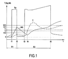
図1に示されるグラフは、複数の曲線、すなわち、燃焼室の下流側の燃焼ガスの温度Tを表す曲線、シャフト12の回転速度NGを表す曲線、および始動噴射装置28によって噴霧された時の燃料圧力Dpを表す曲線を重ね合わせたグラフである。
The graph shown in FIG. 1 includes a plurality of curves, ie, a curve representing the temperature T of the combustion gas downstream of the combustion chamber, a curve representing the rotational speed NG of the shaft 12, and when sprayed by the starting
時間tは、横軸に表示されている。 Time t is displayed on the horizontal axis.
より詳細には、図1は、第1の始動の試みE1が失敗した後に実行される再試行ステップE2を含むのが有利である本発明の始動方法を示している。 More particularly, FIG. 1 shows the start-up method of the present invention that advantageously includes a retry step E2 that is performed after the first start-up attempt E1 fails.
第1の始動の試みの時に、第1の始動ステップS100が実行され、始動装置44がシャフト12を回転駆動するために作動される。このステップは、時間t1の直後に開始される。
During the first start attempt, a first start step S100 is performed and the
時間t1の時点で、第1の点火ステップS110が実行され、始動噴射装置(複数可)が燃料を燃焼室22に噴射し、点火装置自体は始動噴射装置によって噴霧された燃料を着火させるために作動される。言い換えれば、時間t1の後に、始動噴射装置を点火してその後に主噴射装置を点火するのが望ましい。
At time t1, the first ignition step S110 is executed, the starter injector (s) injects fuel into the
時間t1と時間t2との間では、始動装置44によって駆動されるシャフト12の速度は上昇し、その間に始動噴射装置は燃料を噴霧しているが、燃焼室を点火するのに十分に安定した火炎を発生させることができない。その結果、温度Tはほとんど上昇しない。
Between time t1 and time t2, the speed of the shaft 12 driven by the
本発明によれば、温度Tは、時間t2の時点で測定される。時間t2は、シャフト12の回転速度が第1の所定の速度値NG1、具体的には、最大エンジン速度NGmax(この速度は、ほぼ数千回転/分(rpm))の20%を超えた時点に相当する。 According to the invention, the temperature T is measured at time t2. Time t2 is the time when the rotational speed of the shaft 12 exceeds 20% of the first predetermined speed value NG1, specifically, the maximum engine speed NGmax (this speed is approximately several thousand revolutions per minute (rpm)). It corresponds to.
この段階で、検査T120が実行され、測定された温度が第1の所定の温度値T1以上、具体的には250℃以上になれば、検査は合格となる。これは、燃焼が正確に開始されたということ、およびタービンエンジンが正確に始動していることを意味する。 At this stage, inspection T120 is executed, and if the measured temperature is equal to or higher than the first predetermined temperature value T1, specifically 250 ° C. or higher, the inspection passes. This means that combustion has started correctly and that the turbine engine has started correctly.
さもなければ、図示されるように、測定された温度TがT1未満であれば、検査は不合格となる。これは、主噴射装置30が点火されなかったということ、つまり、燃焼が正確に行われなかったということ、ひいてはタービンエンジンが始動しなかったということを意味する。
Otherwise, as shown, if the measured temperature T is less than T1, the test fails. This means that the
この状況で、本発明によれば、再試行ステップS200が実行され、再度ターボシャフトエンジン10の始動が試みられる。
In this situation, according to the present invention, the retry step S200 is executed and the start of the
再試行ステップS200は、連続する以下のステップを含む。 The retry step S200 includes the following successive steps.
まず、停止ステップS210の時に、始動装置44が停止され、同様に始動噴射装置28さらに点火装置32が停止される。その後、シャフト12が始動装置によって駆動されなくなるとシャフト12の速度NGは低下する。
First, at the stop step S210, the
その後、検査T220で、シャフト12の速度NGが第2の所定の速度値NG2、具体的には、上述の最大エンジン速度の10%に達したか否かが判断される。検査T220が不合格である場合、検査は繰り返される。通常、検査T220が合格であれば、シャフト12の速度が点火範囲に戻ったことを意味する。その後、本発明では、始動噴射装置を点火するために第2の点火ステップS230が実行される。このステップでは、始動噴射装置28が燃料を燃焼室22に噴射し、その後、点火装置32が作動される。図1のグラフでは、第2の点火ステップS230は、時間t3の時点で開始される。
Thereafter, in the test T220, it is determined whether or not the speed NG of the shaft 12 has reached a second predetermined speed value NG2, specifically 10% of the above-mentioned maximum engine speed. If inspection T220 fails, the inspection is repeated. Usually, if the inspection T220 is acceptable, it means that the speed of the shaft 12 has returned to the ignition range. Thereafter, in the present invention, a second ignition step S230 is performed to ignite the starting injector. In this step, the starting
その後、第2の始動ステップS250が実行され、再度始動装置がシャフト12を回転駆動するために作動される。検査T240の時に、燃焼室の出口で測定された温度Tが第2の所定の温度値T2、具体的には50℃に達したことが検出された場合、この第2の始動ステップが実行される。図示されている例では、第2の始動ステップS250は、時間t4の時点で実行される。この時点から、再びシャフト12の回転速度NGは上昇する。 Thereafter, a second starting step S250 is performed and the starting device is again activated to drive the shaft 12 in rotation. If it is detected during inspection T240 that the temperature T measured at the outlet of the combustion chamber has reached a second predetermined temperature value T2, specifically 50 ° C., this second starting step is performed. The In the illustrated example, the second starting step S250 is executed at the time t4. From this point, the rotational speed NG of the shaft 12 increases again.
その後、再度、検査T120が実行される。すなわち、シャフト12が再度速度値NG1に達した時点で燃焼室22の出口で温度が測定される。グラフから、この時点で、温度Tが第1の所定の温度値T1より高いことがわかる。これは、主噴射装置30が点火され、ひいてはターボシャフトエンジン10が正確に始動した確率が高いことを示している。
Thereafter, the inspection T120 is performed again. That is, the temperature is measured at the outlet of the
時間t5の時点で、シャフトが第3の所定の速度値NG3、具体的には最大エンジン速度の50%に達すると、ターボシャフトエンジンはもう自律的に動作しているので、始動装置が停止され、同様に始動噴射装置および点火装置が停止される。 At time t5, when the shaft reaches a third predetermined speed value NG3, specifically 50% of the maximum engine speed, the turboshaft engine is already operating autonomously and the starter is stopped. Similarly, the starting injection device and the ignition device are stopped.
Claims (11)
燃焼室(22)に圧縮空気を供給するために燃焼室(22)の上流側に配置された圧縮機ホイール(14)に接続されるシャフト(12)と、
前記シャフト(12)に接続される始動装置(44)と
を備えるタービンエンジン(10)の始動方法にして、
シャフトを回転駆動するために始動装置が作動される第1の始動ステップと、
燃焼室に燃料が噴射され、点火装置が作動される第1の点火ステップと
を含む始動方法であって、
シャフトが第1の所定の速度値(NG1)に達した時に主噴射装置(30)が点火されなかった場合に実行される再試行ステップ(S200)であって、
始動装置と点火装置とが停止される停止ステップ(S210)と、
燃料が燃焼室に噴射され、点火装置が作動される第2の点火ステップ(S230)であって、シャフトの回転速度が第2の所定の速度値(NG2)に達した時に実行される第2の点火ステップ(S230)と、
シャフトを回転駆動するために再度始動装置が作動される第2の始動ステップ(S250)と
を含む再試行ステップ(S200)をさらに含むことを特徴とする、始動方法。 A combustion chamber (22) having an ignition device and at least one main injection device (30), the combustion chamber (22) having an outlet;
A shaft (12) connected to a compressor wheel (14) disposed upstream of the combustion chamber (22) for supplying compressed air to the combustion chamber (22);
A starting method for a turbine engine (10) comprising a starting device (44) connected to the shaft (12);
A first starting step in which a starting device is actuated to drive the shaft in rotation;
A first ignition step in which fuel is injected into a combustion chamber and an ignition device is operated,
A retry step (S200) executed if the main injector (30) is not ignited when the shaft reaches a first predetermined speed value (NG1),
A stop step (S210) in which the starting device and the ignition device are stopped;
A second ignition step (S230) in which fuel is injected into the combustion chamber and the ignition device is operated, and is executed when the rotational speed of the shaft reaches a second predetermined speed value (NG2). Ignition step (S230) of
A starting method, further comprising a retry step (S200) including a second starting step (S250) in which the starting device is actuated again to drive the shaft in rotation.
Applications Claiming Priority (3)
| Application Number | Priority Date | Filing Date | Title |
|---|---|---|---|
| FR1150206A FR2970304B1 (en) | 2011-01-11 | 2011-01-11 | METHOD FOR STARTING A TURBOMACHINE |
| FR1150206 | 2011-01-11 | ||
| PCT/FR2012/050005 WO2012095590A1 (en) | 2011-01-11 | 2012-01-03 | Method for starting a turbomachine |
Publications (2)
| Publication Number | Publication Date |
|---|---|
| JP2014502699A JP2014502699A (en) | 2014-02-03 |
| JP5985508B2 true JP5985508B2 (en) | 2016-09-06 |
Family
ID=44484050
Family Applications (1)
| Application Number | Title | Priority Date | Filing Date |
|---|---|---|---|
| JP2013548874A Expired - Fee Related JP5985508B2 (en) | 2011-01-11 | 2012-01-03 | Turbine engine starting method |
Country Status (11)
| Country | Link |
|---|---|
| US (1) | US9518512B2 (en) |
| EP (1) | EP2663759B1 (en) |
| JP (1) | JP5985508B2 (en) |
| KR (1) | KR101895642B1 (en) |
| CN (1) | CN103299047B (en) |
| CA (1) | CA2823517C (en) |
| ES (1) | ES2528277T3 (en) |
| FR (1) | FR2970304B1 (en) |
| PL (1) | PL2663759T3 (en) |
| RU (1) | RU2594843C2 (en) |
| WO (1) | WO2012095590A1 (en) |
Families Citing this family (6)
| Publication number | Priority date | Publication date | Assignee | Title |
|---|---|---|---|---|
| JP6173171B2 (en) * | 2013-11-06 | 2017-08-02 | 株式会社日立製作所 | Gas turbine starting method and apparatus |
| CN105840318A (en) * | 2016-04-18 | 2016-08-10 | 姚军 | Fast restart method and device of engine |
| US10641179B2 (en) * | 2016-11-07 | 2020-05-05 | General Electric Company | System and method for starting gas turbine engines |
| CN108131205B (en) * | 2017-11-20 | 2019-06-18 | 北京动力机械研究所 | A kind of fanjet startup combustor method |
| FR3076321B1 (en) * | 2017-12-29 | 2022-02-18 | Safran Aircraft Engines | COLD WEATHER TURBOMACHINE STARTING METHOD AND TURBOMACHINE STARTING SYSTEM |
| US20210172376A1 (en) * | 2019-12-10 | 2021-06-10 | General Electric Company | Combustor ignition timing |
Family Cites Families (23)
| Publication number | Priority date | Publication date | Assignee | Title |
|---|---|---|---|---|
| JPS599737B2 (en) * | 1979-02-28 | 1984-03-05 | 株式会社東芝 | Gas turbine starting device |
| JPS5915639A (en) * | 1982-07-19 | 1984-01-26 | Yanmar Diesel Engine Co Ltd | Control device of gas turbine engine |
| JPH01124338U (en) * | 1988-02-17 | 1989-08-24 | ||
| JPH06264767A (en) * | 1993-03-11 | 1994-09-20 | Nissan Motor Co Ltd | Starting equipment of gas turbine engine |
| US5551227A (en) * | 1994-12-22 | 1996-09-03 | General Electric Company | System and method of detecting partial flame out in a gas turbine engine combustor |
| JPH1037762A (en) * | 1996-04-26 | 1998-02-10 | Toshiba Corp | Method and device for controlling power generating plant with gas turbine |
| US5907949A (en) * | 1997-02-03 | 1999-06-01 | United Technologies Corporation | Starting fuel control method for a turbine engine |
| US5844383A (en) * | 1997-07-15 | 1998-12-01 | Sundstrand Corporation | Gas turbine engine starting system and method |
| JP4169952B2 (en) * | 2001-05-30 | 2008-10-22 | 新潟原動機株式会社 | Gas turbine engine restart method and restart device used therefor |
| EP1427928A1 (en) * | 2001-08-27 | 2004-06-16 | Elliott Energy Systems, Inc. | Method for gas turbine light-off |
| US6810676B2 (en) * | 2001-12-14 | 2004-11-02 | Pratt & Whitney Canada Corp. | Method of engine starting in a gas turbine engine |
| JP4027154B2 (en) * | 2002-05-10 | 2007-12-26 | 株式会社アイ・エイチ・アイ・エアロスペース | Gas turbine start-up control method |
| RU2260135C1 (en) * | 2003-11-28 | 2005-09-10 | Открытое акционерное общество "Научно-производственное объединение "Сатурн" (ОАО "НПО "Сатурн") | Gas-turbine engine starting system |
| US7509812B2 (en) * | 2004-08-20 | 2009-03-31 | Hamilton Sundstrand Corporation | Dual ignition system for a gas turbine engine |
| JP2006083730A (en) * | 2004-09-15 | 2006-03-30 | Hitachi Ltd | Firing detection method for gas turbine |
| US7386982B2 (en) * | 2004-10-26 | 2008-06-17 | General Electric Company | Method and system for detecting ignition failure in a gas turbine engine |
| EP1953454A1 (en) | 2007-01-30 | 2008-08-06 | Siemens Aktiengesellschaft | Method of detecting a partial flame failure in a gas turbine engine and a gas turbine engine |
| FR2913250B1 (en) * | 2007-03-02 | 2009-05-29 | Turbomeca Sa | METHOD FOR STARTING A GAS TURBINE HELICOPTER ENGINE, FUEL SUPPLY CIRCUIT FOR SUCH AN ENGINE, AND MOTOR HAVING SUCH A CIRCUIT |
| US7861534B2 (en) * | 2007-05-03 | 2011-01-04 | Pratt & Whitney Canada Corp. | Method of starting turbine engine from low engine speed |
| RU2380560C2 (en) * | 2007-11-12 | 2010-01-27 | Закрытое Акционерное общество "Научно-Производственная Фирма "НЕВТУРБОТЕСТ" (ЗАО НПФ "НЕВТУРБОТЕСТ") | Procedure for power gas-turbine installation start-up |
| ITMI20080164A1 (en) * | 2008-02-04 | 2009-08-05 | Nuovo Pignone Spa | METHOD FOR STARTING A GAS TURBINE |
| FR2947006B1 (en) * | 2009-06-17 | 2014-10-17 | Eurocopter France | DEVICE AND METHOD FOR STARTING A TURBINE ENGINE EQUIPPED WITH A HELICOPTER, IMPLEMENTING AN ELECTRIC POWER SOURCE COMPRISING DISCHARGE SUPPORT ORGANS |
| US8925328B2 (en) * | 2009-10-26 | 2015-01-06 | Siemens Energy, Inc. | Gas turbine starting process |
-
2011
- 2011-01-11 FR FR1150206A patent/FR2970304B1/en not_active Expired - Fee Related
-
2012
- 2012-01-03 JP JP2013548874A patent/JP5985508B2/en not_active Expired - Fee Related
- 2012-01-03 WO PCT/FR2012/050005 patent/WO2012095590A1/en active Application Filing
- 2012-01-03 RU RU2013137429/06A patent/RU2594843C2/en active
- 2012-01-03 PL PL12702576T patent/PL2663759T3/en unknown
- 2012-01-03 ES ES12702576.5T patent/ES2528277T3/en active Active
- 2012-01-03 US US13/979,190 patent/US9518512B2/en active Active
- 2012-01-03 KR KR1020137019498A patent/KR101895642B1/en active IP Right Grant
- 2012-01-03 CN CN201280004905.5A patent/CN103299047B/en active Active
- 2012-01-03 EP EP12702576.5A patent/EP2663759B1/en active Active
- 2012-01-03 CA CA2823517A patent/CA2823517C/en active Active
Also Published As
| Publication number | Publication date |
|---|---|
| EP2663759B1 (en) | 2014-11-19 |
| JP2014502699A (en) | 2014-02-03 |
| EP2663759A1 (en) | 2013-11-20 |
| CA2823517C (en) | 2020-04-14 |
| FR2970304A1 (en) | 2012-07-13 |
| FR2970304B1 (en) | 2013-02-08 |
| CN103299047A (en) | 2013-09-11 |
| RU2013137429A (en) | 2015-02-20 |
| US20130291551A1 (en) | 2013-11-07 |
| CN103299047B (en) | 2016-08-17 |
| RU2594843C2 (en) | 2016-08-20 |
| WO2012095590A1 (en) | 2012-07-19 |
| US9518512B2 (en) | 2016-12-13 |
| ES2528277T3 (en) | 2015-02-06 |
| KR101895642B1 (en) | 2018-10-04 |
| KR20140008330A (en) | 2014-01-21 |
| PL2663759T3 (en) | 2015-04-30 |
| CA2823517A1 (en) | 2012-07-19 |
Similar Documents
| Publication | Publication Date | Title |
|---|---|---|
| JP5985508B2 (en) | Turbine engine starting method | |
| US10907834B2 (en) | Slinger combustor having main combustion chamber and sub-combustion chamber, and gas turbine engine system having the same | |
| US11300054B2 (en) | Fuel flow control system and method for engine start | |
| CA2651746C (en) | Method for the start-up of a gas turbine | |
| US10598040B2 (en) | Method, system and computer program for monitoring a turbomachine start-up sequence by monitoring the speed of the high-pressure spool | |
| US11859555B2 (en) | Systems and methods for starting a gas turbine engine | |
| RU2636602C2 (en) | Method for monitoring engine start cycle of gas-turbine plant | |
| EP2644865A2 (en) | Method of startup control for a gas turbine system operating in a fired deceleration shutdown process mode | |
| US7000405B2 (en) | Gas turbine apparatus and a starting method thereof | |
| US11300055B2 (en) | Method for detecting the ignition of a turbine engine | |
| US8806872B2 (en) | Procedure for igniting a turbine engine combustion chamber | |
| EP3502441A1 (en) | Light-off detection system for gas turbine engines | |
| JPH0355654B2 (en) | ||
| RU2773081C2 (en) | Method for determination of ignition of gas turbine engine | |
| JP7369069B2 (en) | Gas turbine ignition detection method, ignition detection device, gas turbine system, and program | |
| JPH0355653B2 (en) | ||
| JP2006342712A (en) | Fuel control device of gas turbine, starting method and gas turbine power generation facility | |
| JPH0693884A (en) | Gas turbine combustor |
Legal Events
| Date | Code | Title | Description |
|---|---|---|---|
| A521 | Request for written amendment filed |
Free format text: JAPANESE INTERMEDIATE CODE: A523 Effective date: 20141226 |
|
| A621 | Written request for application examination |
Free format text: JAPANESE INTERMEDIATE CODE: A621 Effective date: 20141226 |
|
| A977 | Report on retrieval |
Free format text: JAPANESE INTERMEDIATE CODE: A971007 Effective date: 20160114 |
|
| A131 | Notification of reasons for refusal |
Free format text: JAPANESE INTERMEDIATE CODE: A131 Effective date: 20160119 |
|
| A521 | Request for written amendment filed |
Free format text: JAPANESE INTERMEDIATE CODE: A523 Effective date: 20160413 |
|
| TRDD | Decision of grant or rejection written | ||
| A01 | Written decision to grant a patent or to grant a registration (utility model) |
Free format text: JAPANESE INTERMEDIATE CODE: A01 Effective date: 20160705 |
|
| A61 | First payment of annual fees (during grant procedure) |
Free format text: JAPANESE INTERMEDIATE CODE: A61 Effective date: 20160803 |
|
| R150 | Certificate of patent or registration of utility model |
Ref document number: 5985508 Country of ref document: JP Free format text: JAPANESE INTERMEDIATE CODE: R150 |
|
| R250 | Receipt of annual fees |
Free format text: JAPANESE INTERMEDIATE CODE: R250 |
|
| R250 | Receipt of annual fees |
Free format text: JAPANESE INTERMEDIATE CODE: R250 |
|
| LAPS | Cancellation because of no payment of annual fees |