JP5985405B2 - Waste heat recovery system for oil-cooled gas compressor - Google Patents
Waste heat recovery system for oil-cooled gas compressor Download PDFInfo
- Publication number
- JP5985405B2 JP5985405B2 JP2013013358A JP2013013358A JP5985405B2 JP 5985405 B2 JP5985405 B2 JP 5985405B2 JP 2013013358 A JP2013013358 A JP 2013013358A JP 2013013358 A JP2013013358 A JP 2013013358A JP 5985405 B2 JP5985405 B2 JP 5985405B2
- Authority
- JP
- Japan
- Prior art keywords
- oil
- temperature
- hot water
- heat recovery
- exhaust heat
- Prior art date
- Legal status (The legal status is an assumption and is not a legal conclusion. Google has not performed a legal analysis and makes no representation as to the accuracy of the status listed.)
- Active
Links
- 238000011084 recovery Methods 0.000 title claims description 181
- 239000007789 gas Substances 0.000 title claims description 120
- 239000002918 waste heat Substances 0.000 title claims description 11
- XLYOFNOQVPJJNP-UHFFFAOYSA-N water Substances O XLYOFNOQVPJJNP-UHFFFAOYSA-N 0.000 claims description 258
- 239000003921 oil Substances 0.000 claims description 104
- 230000004087 circulation Effects 0.000 claims description 45
- 238000001816 cooling Methods 0.000 claims description 34
- 239000010687 lubricating oil Substances 0.000 claims description 3
- 239000000498 cooling water Substances 0.000 description 28
- 238000010586 diagram Methods 0.000 description 10
- 238000012360 testing method Methods 0.000 description 7
- 230000000694 effects Effects 0.000 description 6
- 238000005406 washing Methods 0.000 description 4
- 238000004140 cleaning Methods 0.000 description 3
- 230000006835 compression Effects 0.000 description 3
- 238000007906 compression Methods 0.000 description 3
- 239000008400 supply water Substances 0.000 description 3
- 230000007423 decrease Effects 0.000 description 2
- 238000005265 energy consumption Methods 0.000 description 2
- 239000012530 fluid Substances 0.000 description 2
- 230000017525 heat dissipation Effects 0.000 description 2
- 230000005855 radiation Effects 0.000 description 2
- 230000009897 systematic effect Effects 0.000 description 2
- 238000009835 boiling Methods 0.000 description 1
- 230000003247 decreasing effect Effects 0.000 description 1
- 230000002542 deteriorative effect Effects 0.000 description 1
- 238000010438 heat treatment Methods 0.000 description 1
- 238000009434 installation Methods 0.000 description 1
- 238000012986 modification Methods 0.000 description 1
- 230000004048 modification Effects 0.000 description 1
- 238000010792 warming Methods 0.000 description 1
Images


Classifications
-
- F—MECHANICAL ENGINEERING; LIGHTING; HEATING; WEAPONS; BLASTING
- F24—HEATING; RANGES; VENTILATING
- F24H—FLUID HEATERS, e.g. WATER OR AIR HEATERS, HAVING HEAT-GENERATING MEANS, e.g. HEAT PUMPS, IN GENERAL
- F24H1/00—Water heaters, e.g. boilers, continuous-flow heaters or water-storage heaters
- F24H1/18—Water-storage heaters
- F24H1/20—Water-storage heaters with immersed heating elements, e.g. electric elements or furnace tubes
- F24H1/208—Water-storage heaters with immersed heating elements, e.g. electric elements or furnace tubes with tubes filled with heat transfer fluid
-
- F—MECHANICAL ENGINEERING; LIGHTING; HEATING; WEAPONS; BLASTING
- F04—POSITIVE - DISPLACEMENT MACHINES FOR LIQUIDS; PUMPS FOR LIQUIDS OR ELASTIC FLUIDS
- F04B—POSITIVE-DISPLACEMENT MACHINES FOR LIQUIDS; PUMPS
- F04B39/00—Component parts, details, or accessories, of pumps or pumping systems specially adapted for elastic fluids, not otherwise provided for in, or of interest apart from, groups F04B25/00 - F04B37/00
- F04B39/06—Cooling; Heating; Prevention of freezing
-
- F—MECHANICAL ENGINEERING; LIGHTING; HEATING; WEAPONS; BLASTING
- F04—POSITIVE - DISPLACEMENT MACHINES FOR LIQUIDS; PUMPS FOR LIQUIDS OR ELASTIC FLUIDS
- F04B—POSITIVE-DISPLACEMENT MACHINES FOR LIQUIDS; PUMPS
- F04B41/00—Pumping installations or systems specially adapted for elastic fluids
-
- F—MECHANICAL ENGINEERING; LIGHTING; HEATING; WEAPONS; BLASTING
- F04—POSITIVE - DISPLACEMENT MACHINES FOR LIQUIDS; PUMPS FOR LIQUIDS OR ELASTIC FLUIDS
- F04B—POSITIVE-DISPLACEMENT MACHINES FOR LIQUIDS; PUMPS
- F04B53/00—Component parts, details or accessories not provided for in, or of interest apart from, groups F04B1/00 - F04B23/00 or F04B39/00 - F04B47/00
- F04B53/08—Cooling; Heating; Preventing freezing
-
- F—MECHANICAL ENGINEERING; LIGHTING; HEATING; WEAPONS; BLASTING
- F04—POSITIVE - DISPLACEMENT MACHINES FOR LIQUIDS; PUMPS FOR LIQUIDS OR ELASTIC FLUIDS
- F04C—ROTARY-PISTON, OR OSCILLATING-PISTON, POSITIVE-DISPLACEMENT MACHINES FOR LIQUIDS; ROTARY-PISTON, OR OSCILLATING-PISTON, POSITIVE-DISPLACEMENT PUMPS
- F04C29/00—Component parts, details or accessories of pumps or pumping installations, not provided for in groups F04C18/00 - F04C28/00
- F04C29/04—Heating; Cooling; Heat insulation
-
- Y—GENERAL TAGGING OF NEW TECHNOLOGICAL DEVELOPMENTS; GENERAL TAGGING OF CROSS-SECTIONAL TECHNOLOGIES SPANNING OVER SEVERAL SECTIONS OF THE IPC; TECHNICAL SUBJECTS COVERED BY FORMER USPC CROSS-REFERENCE ART COLLECTIONS [XRACs] AND DIGESTS
- Y02—TECHNOLOGIES OR APPLICATIONS FOR MITIGATION OR ADAPTATION AGAINST CLIMATE CHANGE
- Y02P—CLIMATE CHANGE MITIGATION TECHNOLOGIES IN THE PRODUCTION OR PROCESSING OF GOODS
- Y02P80/00—Climate change mitigation technologies for sector-wide applications
- Y02P80/10—Efficient use of energy, e.g. using compressed air or pressurized fluid as energy carrier
- Y02P80/15—On-site combined power, heat or cool generation or distribution, e.g. combined heat and power [CHP] supply
Description
本発明は油冷式ガス圧縮機における排熱回収システムに関し、特に油冷式の空気圧縮機からの排熱を回収するシステムに関する。 The present invention relates to an exhaust heat recovery system in an oil-cooled gas compressor, and more particularly to a system for recovering exhaust heat from an oil-cooled air compressor.
工場全体で消費されるエネルギーのうち、空気圧縮機などのガス圧縮機によって消費される総合エネルギーは、20〜25%に相当すると言われており、ガス圧縮機からの排熱を回収する効果は大きい。特に、地球温暖化問題を発端としたCO2排出量の削減目標達成のためにも、ガス圧縮機からの排熱利用は、今後更に重要視されてくると予想される。 It is said that the total energy consumed by a gas compressor such as an air compressor is equivalent to 20 to 25% of the energy consumed in the whole factory, and the effect of recovering exhaust heat from the gas compressor is large. In particular, it is expected that the use of exhaust heat from gas compressors will become more important in the future in order to achieve the CO 2 emission reduction target due to the global warming problem.
ガス圧縮機は、空気などのガスを圧縮する圧縮機本体、圧縮により発生する熱を吸収する冷却系統、圧縮機の駆動力源であるモータなどにより構成される。また、ガス圧縮機では、モータ入力電力を100%とすると、冷却系統において吸収される熱量はそのうちの90%以上にも相当し、その熱量は、通常外気に放出されており、非常に多くのエネルギーが大気に排出されている。排熱量を低減するため、圧縮機本体やモータの高効率化が推進されているが、その効果は数%が限界であり、ガス圧縮機からの排熱の有効利用が求められる。 The gas compressor includes a compressor body that compresses a gas such as air, a cooling system that absorbs heat generated by the compression, a motor that is a driving force source of the compressor, and the like. Further, in a gas compressor, assuming that the motor input power is 100%, the amount of heat absorbed in the cooling system is equivalent to 90% or more of that, and the amount of heat is normally released to the outside air, and a great amount Energy is released into the atmosphere. In order to reduce the amount of exhaust heat, higher efficiency of the compressor body and the motor is being promoted, but the effect is limited to several percent, and effective use of exhaust heat from the gas compressor is required.
ガス圧縮機からの排熱の有効利用に関しては、暖房への利用、温水活用、ボイラーの給水予熱への活用などの事例がある。
なお、この種の従来技術としては特許第4329875号公報(特許文献1)や特開2012−67743号公報(特許文献2)に記載のものなどがある。
前記特許文献1のものは、蒸気を用いて圧縮機を駆動すると共に、圧縮機で発生する熱を、ボイラーに供給する水(給水)の予熱に利用して、ボイラーでの消費エネルギーを削減させるようにしたものである。
前記特許文献2のものは、油冷式ガス圧縮機に排熱回収熱交換器を設け、圧縮機を冷却して加熱された油などからの排熱回収を可能としたものである。
Examples of effective use of exhaust heat from gas compressors include heating, hot water, and boiler water preheating.
In addition, as this kind of prior art, there exist a thing of patent 4329875 (patent document 1) and Unexamined-Japanese-Patent No. 2012-67743 (patent document 2).
In
In Patent Document 2, an exhaust heat recovery heat exchanger is provided in an oil-cooled gas compressor, and exhaust heat recovery from oil heated by cooling the compressor is made possible.
上記特許文献1のものでは、空気圧縮機で発生する熱を、ボイラーの給水予熱として活用しているもので、空気圧縮機の冷却系統として1つの水冷冷却系統を有し、空気圧縮機で発生した熱を前記水冷冷却系統の水で吸収し、これにより温度上昇した水をボイラーへの供給水と混合させることにより、ボイラー供給水温度を上昇させ、ボイラーでの消費エネルギーを削減するものである。
The thing of the said
この特許文献1のものでは、空気圧縮機で発生した熱により給水タンクへの補給水の温度を上昇させることはできるが、この補給水の温度は、水量を極限まで絞った条件でも、空気圧縮機の吐出温度より数十度低い温度になる。また、圧縮機の負荷率が低くなるほど、前記補給水の温度は低くなってしまう。
In this
従って、特許文献1に記載のような排熱回収システムでは、補給水などの水の温度を圧縮機排熱を利用して単に上昇させれば良いというシステムには利用できるが、供給する温水に要求温水温度下限がある場合や、前記要求温水温度下限が圧縮機吐出温度よりも数度しか低くないという条件では、その要求温度の温水を供給できないという課題がある。また、補給水温度を上昇させる為に水量を絞ると熱交換率も悪くなるという課題もある。
Therefore, the exhaust heat recovery system described in
上記特許文献2のものでは、排熱回収熱交換器で、油配管を流れる高温の油及びガス配管を流れる高温の圧縮空気と、排熱回収機器からの冷却水とを熱交換させて、冷却水を加熱するようにしているが、油冷式ガス圧縮機のアンロード運転(無負荷運転)時や停止状態となった場合における前記排熱回収熱交換器からの放熱に関しては配慮が為されていない。このため前記排熱回収機器の冷却水(温水)温度が高い場合、油冷式ガス圧縮機のアンロード運転時や停止時には前記排熱回収機器側からの放熱が生じて、排熱回収率を悪化させるという課題がある。 In the above-mentioned Patent Document 2, the exhaust heat recovery heat exchanger performs heat exchange between the hot oil flowing through the oil piping and the hot compressed air flowing through the gas piping and the cooling water from the exhaust heat recovery equipment, and cooling Although water is heated, consideration is given to heat dissipation from the exhaust heat recovery heat exchanger when the oil-cooled gas compressor is unloaded (no-load operation) or stopped. Not. For this reason, when the temperature of the cooling water (warm water) of the exhaust heat recovery device is high, heat is dissipated from the exhaust heat recovery device when the oil-cooled gas compressor is unloaded or stopped, and the exhaust heat recovery rate is reduced. There is a problem of making it worse.
本発明の目的は、圧縮機負荷率が低い場合でも要求温度の温水を供給することが可能であり、しかも排熱回収機器側からの放熱を抑制して排熱回収率を向上することのできる油冷式ガス圧縮機における排熱回収システムを得ることにある。 The object of the present invention is to supply hot water at a required temperature even when the compressor load factor is low, and to improve the exhaust heat recovery rate by suppressing the heat radiation from the exhaust heat recovery device side. The object is to obtain an exhaust heat recovery system in an oil-cooled gas compressor.
上記課題を解決するため本発明は、圧縮機本体と、該圧縮機本体から吐出された圧縮ガスから油を分離する油分離器と、この油分離器で油を分離された圧縮ガスを需要先に送るためのガス配管と、前記油分離器で分離された油を前記圧縮機本体に戻すための油配管と、前記ガス配管を流れる圧縮ガスと前記油配管を流れる油の少なくとも何れかから熱回収するための排熱回収熱交換器とを備える油冷式ガス圧縮機における排熱回収システムであって、前記排熱回収熱交換器で受け取った熱を温水として貯える貯温水タンクと、前記排熱回収熱交換器で受け取った熱を前記貯温水タンクに移動させるために、熱媒体を前記排熱回収熱交換器と前記貯温水タンクとの間に循環させる循環回路と、この循環回路に設けられた循環用ポンプと、前記排熱回収熱交換器で熱交換される前記油または前記圧縮ガスの温度が前記貯温水タンク内の温水温度以下の場合に、前記循環用ポンプを停止させるかその回転数を低下させるように制御する制御装置を備えることを特徴とする。 In order to solve the above problems, the present invention provides a compressor main body, an oil separator that separates oil from the compressed gas discharged from the compressor main body, and a compressed gas separated from the oil by the oil separator. Heat from at least one of a gas pipe for sending to the oil pipe, an oil pipe for returning the oil separated by the oil separator to the compressor body, a compressed gas flowing through the gas pipe, and an oil flowing through the oil pipe An exhaust heat recovery system in an oil-cooled gas compressor comprising an exhaust heat recovery heat exchanger for recovering, wherein a hot water storage tank for storing heat received by the exhaust heat recovery heat exchanger as hot water, and the exhaust In order to move the heat received by the heat recovery heat exchanger to the hot water storage tank, a circulation circuit for circulating a heat medium between the exhaust heat recovery heat exchanger and the hot water tank, and provided in the circulation circuit A circulating pump, and the exhaust Control for controlling to stop the circulation pump or reduce its rotational speed when the temperature of the oil or the compressed gas to be heat exchanged in the recovery heat exchanger is equal to or lower than the hot water temperature in the hot water storage tank A device is provided.
本発明によれば、圧縮機負荷率が低い場合でも要求温度の温水を供給することが可能であり、しかも排熱回収機器側からの放熱を抑制して排熱回収率を向上することのできる油冷式ガス圧縮機における排熱回収システムを得ることができる。 According to the present invention, it is possible to supply hot water at a required temperature even when the compressor load factor is low, and it is possible to improve the exhaust heat recovery rate by suppressing the heat radiation from the exhaust heat recovery device side. An exhaust heat recovery system in an oil-cooled gas compressor can be obtained.
以下、本発明の油冷式ガス圧縮機における排熱回収システムの具体的実施例を、図面を用いて説明する。各図において、同一符号を付した部分は同一或いは相当する部分を示している。 Hereinafter, specific examples of the exhaust heat recovery system in the oil-cooled gas compressor of the present invention will be described with reference to the drawings. In each figure, the part which attached | subjected the same code | symbol has shown the part which is the same or it corresponds.
本発明の油冷式ガス圧縮機における排熱回収システムの実施例1を図1に示す系統図により説明する。
図1において、3は圧縮機本体で、本実施例では油冷式のスクリュー空気圧縮機で構成されている。前記圧縮機本体3がモータ4により駆動されると、圧縮機ユニット20内に吸込まれたガス(空気)は、吸込フィルタ1及び吸込絞り弁2を介して前記圧縮機本体3内に吸引された後、圧縮されて吐出され、油分離器(オイルタンク)6に流入する。5は吐出温度センサ(圧縮機本体出口温度センサ)(T1)で、前記圧縮機本体3から吐出された圧縮ガス(圧縮空気)の温度を検出するものである。この吐出温度センサ5により温度が検出された後、前記圧縮ガスは前記油分離器6に流入する。
A first embodiment of the exhaust heat recovery system in the oil-cooled gas compressor of the present invention will be described with reference to the system diagram shown in FIG.
In FIG. 1,
この油分離器6に流入する前記圧縮ガスには油(潤滑油)が混合されており、前記油分離器6内では、圧縮ガスと油が遠心分離されて、圧縮ガスは、油分離器6上部のガス配管(空気配管)8から流出して、水冷熱交換器で構成された排熱回収熱交換器10に流入する。前記油分離器6下部に溜まった油は、油配管7から流出し、温調弁9により、油温が高い場合には前記排熱回収熱交換器10側に流れ、油温が低い場合には前記オイルフィルタ16側にバイパスして流れる。前記オイルフィルタ16を通過した油は再び前記圧縮機本体3に流入するように構成されている。
The compressed gas flowing into the
前記排熱回収熱交換器10は、貯温水タンクユニット(排熱回収機器)23に接続されている。この貯温水タンクユニット23が稼動している場合には、熱媒体(水などの流体)を循環配管(熱媒体入口配管17及び熱媒体出口配管18)を介して前記排熱回収熱交換器10に循環させており、排熱回収熱交換器10への熱媒体入口配管17から前記熱媒体を流入させて、熱媒体出口配管18から温度の上昇した熱媒体として回収することで、前記圧縮機本体3で発生する圧縮熱の熱量を前記貯温水タンクユニット23で回収するように構成している。
The exhaust heat
即ち、前記排熱回収熱交換器10では、油配管7を流れる高温の油及びガス配管8を流れる高温の圧縮ガスと、前記貯温水タンクユニット23からの熱媒体とが熱交換して、前記熱媒体は加熱されると共に、前記圧縮ガスと油は冷却されるように構成されている。
That is, in the exhaust heat
前記排熱回収熱交換器10は、排熱回収ユニット21内に配置されている。また、前記貯温水タンクユニット23には水(水とは温水である場合も含む)を溜める貯温水タンク19が設けられ、この貯温水タンク19には水を供給するための水入口配管27と、貯温水タンク19で温度の上昇した水(温水)を温水供給先に送るための温水出口配管28が接続されている。また、前記貯温水タンク19内には水対水熱交換器24が設置されており、前記循環配管を流れる熱媒体と前記貯温水タンク19内の水(温水)とが熱交換することで貯温水タンク19内の水の温度を上昇させるように構成されている。
The exhaust heat
また、前記循環配管には前記熱媒体を循環させるための循環ポンプ22が設けられている。本実施例では、前記循環ポンプ22は、前記貯温水タンクユニット23内の前記熱媒体入口配管17に設置されているが、前記熱媒体出口配管18に設置するようにしても良い。前記循環用ポンプ22により、前記循環配管17,18を介して前記熱媒体を、前記排熱回収熱交換器10と前記貯温水タンク19とに何度も循環させることが可能となる。これにより、前記貯温水タンク19内の水を予め決めた所定の温度まで上昇させることが可能となる。また、空気圧縮機の負荷率が小さくなった場合でも、空気圧縮機は基本的にその負荷率に関係なく吐出温度を保つことが可能であるため、空気圧縮機の負荷率に関係なく要求温度の温水供給が可能となる。従って、要求温水温度下限がある場合で、更にその要求温水温度下限が圧縮機吐出温度より数度しか低くないというような場合であっても、圧縮機の負荷率に関係なく、要求温度の温水を供給することが可能になる。
The circulation pipe is provided with a
前記排熱回収熱交換器10の下流側には空冷熱交換器13が設けられており、前記排熱回収熱交換器10を通過した前記圧縮ガスと油は、この空冷熱交換器13も通過するように構成されている。即ち、前記圧縮ガスと油は、前記排熱回収熱交換器10において前記循環する熱媒体により冷却された後、或いは前記循環ポンプ22が停止している場合には熱媒体との熱交換がされない状態で前記空冷熱交換器13に流入する。この空冷熱交換器13では、冷却ファン14により送風される冷却風により前記圧縮ガスと油を冷却できるように構成されている。
An air-cooled
15は前記冷却ファン14を駆動するファンモータで、インバータ29により回転数制御が可能な構成となっている。従って、前記排熱回収熱交換器10から出た前記圧縮ガスや油の温度が所定温度よりも高い場合にはその温度に応じて冷却ファン14の回転数を制御することにより、前記圧縮ガスや油の温度を所定の範囲にして供給することが可能な構成となっている。
前記空冷熱交換器13を出た圧縮ガスは圧縮機ユニット20外の需要先に供給され、また前記油は、前記温調弁9によりバイパスされた油がある場合にはその油と合流した後、前記オイルフィルタ16を介して圧縮機本体3に注入される。
The compressed gas leaving the air-cooled
次に、前記冷却ファン14の回転数を制御することにより、前記圧縮ガスや油の温度を所望の温度にして供給する制御について詳しく説明する。
30は前記ファンモータ15の回転数を制御する制御装置で、この制御装置30には、前記吐出温度センサ5からの吐出温度情報、及び前記排熱回収熱交換器10下流側における温度センサ(ガス温度センサ)(TA)11からの圧縮空気(圧縮ガス)の温度情報、温度センサ(油温度センサ)(TO)12からの油の温度情報が入力される。
Next, control for supplying the compressed gas and oil at a desired temperature by controlling the number of rotations of the cooling
これらの温度情報に基づいて、前記制御装置30は、前記吐出温度センサ5で検出される圧縮空気の吐出温度が予め設定されている目標吐出温度との温度差が小さくなるように、前記インバータ29を介して前記ファンモータ15を制御し、冷却ファン14の回転数を変化させて、圧縮機本体3に注入される油を適正な温度に冷却する。この冷却された油はオイルフィルタ16を介して圧縮機本体3に注入される。
Based on the temperature information, the
即ち、前記排熱回収熱交換器10での熱交換量が少ない場合には、前記空冷熱交換器13での熱交換量が増加するように、排熱回収熱交換器10での熱交換量が多い場合には、空冷熱交換器13での熱交換量が低減するように、前記冷却ファン14の回転速度は制御される。
That is, when the heat exchange amount in the exhaust heat
前記排熱回収熱交換器10及び前記空冷熱交換器13でのそれぞれの熱交換器容量は、圧縮機本体3で発生する全熱量をそれぞれ単独で処理可能な容量に設計されている。このため、前記排熱回収熱交換器10において最大の熱回収が行われた場合、該排熱回収熱交換器10から出た潤滑油及び圧縮空気の温度は十分に冷却されているので、前記空冷熱交換器13においては前記ファンモータ15が停止される場合もある。
The heat exchanger capacities of the exhaust heat
油冷式スクリュー空気圧縮機の場合、圧縮機ユニット20に内に充填されている油の循環回数(圧縮機本体3から吐出された油が再び圧縮機本体に戻る循環回数)は一般に2〜5回/分程度と多いため、前記冷却ファン14の回転速度が変化すると前記吐出温度センサ5で検出される吐出圧縮空気の温度も比較的敏感に変化する。従って、吐出温度センサ5の温度に応じて、冷却ファン14の回転速度を変化させるインバータ制御を行うことにより、圧縮機本体3から吐出される圧縮空気の温度をほぼ目標吐出温度(所定範囲の吐出温度)に制御することが可能である。
In the case of an oil-cooled screw air compressor, the number of circulations of the oil filled in the compressor unit 20 (the number of circulations in which the oil discharged from the
なお、本実施例では、前記温度センサ(TA)11及び前記温度センサ(TO)12も備えているので、前記空冷熱交換器13に流入する圧縮空気の温度及び油の温度が分かることから、これらの温度センサ11,12からの温度情報も考慮して前記冷却ファン14の回転速度を調整することも可能となり、圧縮機本体3から吐出される圧縮空気の温度をより迅速に精度良く目標温度に近づけることが可能となる。
In this embodiment, since the temperature sensor (TA) 11 and the temperature sensor (TO) 12 are also provided, the temperature of the compressed air and the temperature of the oil flowing into the air-cooled
以上のように、前記冷却ファン14の回転数制御を実施することにより、前記貯温水タンクユニット23での排熱回収状況(稼働状況)に関係なく、つまり、前記排熱回収熱交換器10での熱交換量に関係なく、前記吐出温度センサ5の温度が一定となるように、圧縮機ユニット20を稼働させることが可能となる。
As described above, by controlling the rotation speed of the cooling
前記貯温水タンクユニット23内には、前記排熱回収熱交換器10と前記貯温水タンク19との間に熱媒体を循環させる前記循環配管17,18のうち、前記熱媒体出口配管18を流れる熱媒体の温度を検出する温度センサ(熱媒体温度センサ)(Tw1)25、前記貯温水タンク19内の温水温度を検出する温度センサ(温水温度センサ)(Tw2)26、及び制御装置31が設けられている。この制御装置31には、前記温度センサ25及び前記温度センサ26の温度情報が入力され、これらの温度情報に基づいて、前記制御装置31は前記循環ポンプ22の制御を実施するように構成されている。例えば、前記温度センサ(Tw2)26で検出された温度が、予め定めた所定温度(例えば、温水供給先での要求温度)を超えた場合に、前記循環ポンプ22を停止させるか或いはその回転数を低下させるように制御する。
In the hot water
また、前記温度センサ(Tw1)25で検出された温度が、前記温度センサ(Tw2)26で検出された温度よりも、低い或いは所定温度以上低い場合には、前記貯温水タンク19内の温水温度を低下させるおそれがあるので、この場合にも前記循環ポンプ22を停止させるか或いはその回転数を低下させるようにしても良い。
When the temperature detected by the temperature sensor (Tw1) 25 is lower than the temperature detected by the temperature sensor (Tw2) 26 or lower than a predetermined temperature, the hot water temperature in the
また、前記制御装置31には、前記温度センサ25,26から入力された温度情報などを外部へ出力するための出力端子としての機能を持たせることができる。即ち、前記制御装置31から出力された前記温度センサ25,26の温度情報に基づいて、前記水入口配管27や温水出口配管28での温水制御に使用することができる。例えば、温度センサ(Tw2)26で検出された温度が予め定めた所定温度(温水供給先での要求温度)以上となった場合には、前記温水出口配管28に設けた弁(図示せず)を開として温水を供給先に供給し、同時に前記水入口配管27に設けた弁(図示せず)も開として、前記貯温水タンク19内に水を補給するように制御することができる。
Further, the
また、前記温度センサ25,26からの温度情報を、前記制御装置31から、外部の表示装置や、排熱回収システム全体を制御する後述する制御装置32などに出力することもできる。
Further, the temperature information from the
32は図1に示す油冷式ガス圧縮機における排熱回収システム全体を制御する制御装置で、この制御装置32は、前記貯温水タンクユニット23内、或いは前記圧縮機ユニット20内に設けられている。そして、この制御装置32には、前記温度センサ(TO)12で検出された油温度の情報及び前記温度センサ(Tw2)26で検出された貯温水タンク19内の温水温度の情報が入力され、前記温度センサ12で検出された温度が、前記温度センサ26で検出された温度以下となった場合、前記循環ポンプ22を停止させる、或いはその回転数を下げるように制御する。
32 is a control device for controlling the entire exhaust heat recovery system in the oil-cooled gas compressor shown in FIG. 1, and this control device 32 is provided in the hot
なお、この制御装置32には前記温度センサ(TA)11で検出された圧縮ガス温度の情報も前記制御装置30を介して入力可能に構成されているので、この温度センサ11で検出された温度が、前記温度センサ26で検出された温度以下となった場合に、前記循環ポンプ22を停止させる、或いはその回転数を下げるように制御しても良い。
The control device 32 is configured so that the information of the compressed gas temperature detected by the temperature sensor (TA) 11 can also be input via the
また、前記制御装置32には、前記温度センサ(TA)11、前記温度センサ(TO)12、前記温度センサ(Tw2)26から入力された温度情報を外部に出力するための出力端子としての機能を持たせることもできる。 The control device 32 functions as an output terminal for outputting temperature information input from the temperature sensor (TA) 11, the temperature sensor (TO) 12, and the temperature sensor (Tw2) 26 to the outside. Can also be given.
前記圧縮機ユニット20が停止状態や無負荷運転状態の場合、前記排熱回収熱交換器10で受け取れる排熱回収熱量は少量である。また、前記貯温水タンク19内の温水温度よりも前記排熱回収熱交換器10での油配管を流れる油の温度の方が低い場合、前記循環回路を流れる熱媒体を介して前記貯温水タンク19内の熱が前記排熱回収熱交換器10へ移動してしまうので、排熱回収率を悪化させる。
When the
これに対し、本実施例では、上述したように、温度センサ(TO)12或いは温度センサ(TA)11で検出された温度が、温度センサ(Tw2)26で検出された温度以下となった場合、前記循環ポンプ22を例えば停止させるように制御する。従って、本実施例によれば、排熱回収率の悪化を防止することが可能となる。
On the other hand, in the present embodiment, as described above, when the temperature detected by the temperature sensor (TO) 12 or the temperature sensor (TA) 11 is equal to or lower than the temperature detected by the temperature sensor (Tw2) 26. The
また、前記制御装置32から外部に出力された前記温度情報を基にして、前記水入口配管27や温水出口配管28の制御に使用することもできる。即ち、温度センサ(TO)12或いは温度センサ(TA)11の検出温度が温度センサ(Tw2)26の検出温度以下となった場合、貯温水タンク19内の温水の更なる温度上昇は望めないので、この場合にも、温水出口配管28に設けた前記弁を開として温水を活用し、水入口配管27に設けた前記弁も開いて水を貯温水タンク19内に補給するようにしても良い。
Further, it can be used for controlling the
なお、図1に示す実施例では、前記制御装置32により、排熱回収熱交換器10で熱交換される油または圧縮ガスの温度が、温水温度センサ26で検出された貯温水タンク内の温水温度以下の場合に、前記循環用ポンプ22を停止させるかその回転数を低下させるように制御する例について述べたが、次のように制御しても良い。
In the embodiment shown in FIG. 1, the temperature of the oil or compressed gas heat-exchanged by the exhaust heat
即ち、前記制御装置32により、排熱回収熱交換器10で熱交換される油または圧縮ガスの温度が、前記熱媒体温度センサ25で検出された温度以下の場合に、前記循環用ポンプ22を停止させるかその回転数を低下させるように制御しても良い。
即ち、前記温水温度センサ26は貯温水タンク19の上方の温度を検出しているので、通常は、前記熱媒体温度センサ25で検出される温度は前記温水温度センサ26で検出される温度とほぼ近い温度になっている。従って、前記熱媒体温度センサ25で検出された温度を用いて制御しても、前記温水温度センサ26を用いて制御した場合とほぼ同様の効果が得られる。
That is, when the temperature of the oil or compressed gas heat-exchanged by the exhaust heat
That is, since the hot
また、前記圧縮機本体3が停止状態や無負荷運転状態の場合で、貯温水タンク19内の温水温度が、沸き上げ途中の状態では、貯温水タンク19内の温水温度が上方で高く、下方では低くなっている。このため、水対水熱交換器24で熱媒体は低温の水とも熱交換するため、熱媒体入口配管17を流れる熱媒体温度は温水温度センサ26で検出される温度よりも低下している。この状態では排熱回収熱交換器10内での油や圧縮ガスの温度が前記温水温度センサ26で検出された温度よりも低い場合もありうる。しかし、このような状態であっても、前記熱媒体温度センサ25で検出される温度が前記油温度センサ12或いはガス温度センサ11で検出される温度より低い場合には、排熱回収をしていることになるので、循環ポンプ22の駆動を継続した方が良い。
Further, when the compressor
一方、前記油温度センサ12或いはガス温度センサ11で検出される温度が、前記熱媒体温度センサ25で検出される温度より低い場合には、熱媒体側から油或いは圧縮ガス側に熱移動させることになるので、この場合には循環ポンプ22を停止させる。このように制御することにより、排熱回収率を向上することができる。
On the other hand, when the temperature detected by the
また、本実施例では、前記制御装置32は、温度センサ(TO)12或いは温度センサ(TA)11の検出温度と、温度センサ(Tw2)26または温度センサ(Tw1)25の検出温度を比較して制御する例を説明した。しかし、前記吐出温度センサ(T1)5で検出された温度情報も前記制御装置30を介して前記制御装置32に入力されるように構成されているので、前記温度センサ(TO)12或いは温度センサ(TA)11の代わりに、前記吐出温度センサ(T1)5の検出温度を用いて前記の制御をすることもでき、このようにしてもほぼ同様の効果を得ることができる。更に、前記温度センサ5、11、12の全ての検出温度を用いて制御すれば、より精度の高い制御が可能となる。
In this embodiment, the control device 32 compares the temperature detected by the temperature sensor (TO) 12 or the temperature sensor (TA) 11 with the temperature detected by the temperature sensor (Tw2) 26 or the temperature sensor (Tw1) 25. An example of controlling is described. However, since the temperature information detected by the discharge temperature sensor (T1) 5 is also input to the control device 32 via the
なお、本実施例では、前記温水温度センサ(Tw2)26を貯温水タンク19の上部に1個だけ設置した例を示したが、前記温水温度センサ26の設置位置は上部に限られず例えば中央部付近に設置するようにしても良い。好ましくは、前記水対水熱交換器24よりも上部に設置すると良い。また、前記温水温度センサ26を貯温水タンク19内の上下方向に複数個設置し、これら複数の温度センサを用いて制御すれば、より排熱回収率を向上させることのできる排熱回収システムとすることも可能となる。
In the present embodiment, an example in which only one hot water temperature sensor (Tw2) 26 is installed in the upper part of the
また、前記吐出温度センサ5で検出された温度が、前記油温度センサ12または前記ガス温度センサ11の少なくとも何れかで検出された温度よりも低い場合には、前記排熱回収熱交換器10で熱交換される前記油または前記圧縮ガスの温度が、前記貯温水タンク19内の温水温度よりも低くなっていると考えられる。従って、制御装置32は、吐出温度センサ5で検出された温度が、油温度センサ12またはガス温度センサ11の少なくとも何れかで検出された温度よりも低い場合には、排熱回収熱交換器10で熱交換される油または圧縮ガスの温度が、貯温水タンク19内の温水温度よりも低くなっていると判定し、前記循環用ポンプ22を停止させるかその回転数を低下させるようにしても良い。
When the temperature detected by the
図2は図1に示す油冷式ガス圧縮機における排熱回収システムにおいて、圧縮機本体3から吐出される圧縮ガス温度を約100℃(図2には「吐出温度99℃」と表記)とし、排熱回収熱交換器10に冷却水を何度も循環させるのではなく、1度だけ通水したときの、冷却水量と、通水した冷却水の排熱回収熱交換器出口での温度上昇との関係の試験結果を示す線図である。
FIG. 2 shows that in the exhaust heat recovery system for the oil-cooled gas compressor shown in FIG. 1, the temperature of the compressed gas discharged from the
図2の試験結果を利用し、本実施例1による具体的な排熱回収熱交換器10での温度上昇の効果について説明する。この試験結果は、図1に示す排熱回収システムにおいて、貯温水タンク19が存在しない排熱回収システムで試験を行った結果である。横軸は排熱回収熱交換器10への冷却水量を示し、縦軸は排熱回収熱交換器10を通過後の温水の温度上昇を示す。また、線図は、前記排熱回収熱交換器10における油配管7側(オイルクーラOC側)と、ガス配管8側(エアクーラAC側)とを合せた排熱回収によって得られた冷却水の温度(温度上昇)を示すものである。
A specific effect of the temperature rise in the exhaust heat
図2から分かるように、冷却水量を絞るほど高い温水温度を得られるが、冷却水量が2L/min以下では、排熱回収熱交換器10の能力の限界によって、冷却水量を更に絞っても温水温度を上昇させることができず、温水温度の上昇は80℃で限界となる。つまり、排熱回収熱交換器10への通水が1回限りの場合(即ち、1パス通水の場合)、圧縮機本体出口を約100℃になるよう設定した油冷式スクリュー圧縮機(この例では22kWの容量のものを使用)からの排熱回収によって得られる温水の温度は80℃までの温度上昇が限界である。
As can be seen from FIG. 2, the hot water temperature can be increased as the cooling water amount is reduced, but if the cooling water amount is 2 L / min or less, the hot water can be reduced even if the cooling water amount is further reduced due to the limit of the capacity of the exhaust heat
これに対して、図1に示す油冷式ガス圧縮機における排熱回収システムの場合、貯温水タンク19と排熱回収熱交換器10の間を、循環配管17,18を介して、水(温水)を何度でも循環させるため(1回限りの通水ではなく何度も循環させるマルチパス通水であるため)、貯温水タンク19内の温度を、最終的には圧縮機吐出温度に近い温度、例えば約93℃まで上昇させることが可能となる。即ち、同じ条件での前記1回限りの通水(1パス通水)の場合に比較して、10℃以上温度が高い約93℃の高温の温水を得ることができる。また、排熱回収熱交換器10への通水が1回限りの場合、圧縮機の負荷率が低いと得られる温水温度も低下する。しかし、圧縮機は基本的に負荷率に関係なく吐出温度を保つことが可能であるから、上記本実施例の構成とすることにより、圧縮機の負荷率に関係なく、要求温度の温水供給が可能となる。
On the other hand, in the case of the exhaust heat recovery system in the oil-cooled gas compressor shown in FIG. 1, between the hot
図3は図1に示す油冷式ガス圧縮機における排熱回収システムにおいて、圧縮機本体3から吐出される圧縮ガス温度を約78℃とし、排熱回収熱交換器10に冷却水を何度も循環させるのではなく、1度だけ通水したときの、冷却水量と、通水した冷却水による排熱回収率との関係の試験結果を示す線図である。
FIG. 3 shows an exhaust heat recovery system for the oil-cooled gas compressor shown in FIG. 1. The temperature of the compressed gas discharged from the
図3は、図2と同様に、図1に示す排熱回収システムにおいて、貯温水タンク19が存在しない排熱回収システムで試験を行った結果である。横軸は排熱回収熱交換器10への冷却水量を示し、縦軸は排熱回収熱交換器10への冷却水の通水による排熱回収率を示している。また、線図は、前記排熱回収熱交換器10における油配管7側(オイルクーラOC側)と、ガス配管8側(エアクーラAC側)とを合せた排熱回収による排熱回収率を示している。ここで、排熱回収率とは、排熱回収熱交換器10で受け取った熱量を圧縮機の総合入力で割った値であり、排熱回収率が高いほど圧縮機排熱を有効活用していることになる。
FIG. 3 shows the result of testing in the exhaust heat recovery system shown in FIG. 1 using the exhaust heat recovery system in which the hot
図3から分かるように、冷却水量を絞るほど排熱回収率が低くなり、前述した図2において、最高温水温度を確保できる冷却水量2L/minでは、図3に示すように、排熱回収率は10%程度しかなく、排熱回収の効率が非常に悪いことがわかる。つまり、1回の通水のみで温水を生成する場合で、ある程度高温の温水が求められる場合、冷却水量を絞る必要があるので、排熱回収率は非常に低くなってしまう。 As can be seen from FIG. 3, the exhaust heat recovery rate decreases as the amount of cooling water is reduced. In FIG. 2, the exhaust heat recovery rate is as shown in FIG. 3 at a cooling water amount of 2 L / min that can secure the maximum hot water temperature. Is only about 10%, and it can be seen that the efficiency of exhaust heat recovery is very poor. That is, in the case where warm water is generated by only one water flow and warm water that is hot to some extent is required, the amount of cooling water needs to be reduced, so the exhaust heat recovery rate becomes very low.
逆に、冷却水量を多くしていくと、ある程度の冷却水量以上(図3では10L/min以上)では、排熱回収率を80%近くまで上昇させることができ、またそれ以上に冷却水量を増やしても、排熱回収率をそれ以上は上昇できないが高い値に維持できる。即ち、図3の試験結果で言えば、冷却水量を10L/min以上(例えば20L/min)とすることにより、高い排熱回収率での熱交換をさせることができる。従って、図1に示す本実施例において、この冷却水量(例えば20L/minの循環水量)に設定することにより、高温の温水が得られるだけでなく、排熱回収率も高い排熱回収システムとすることができる。 Conversely, if the amount of cooling water is increased, the exhaust heat recovery rate can be increased to nearly 80% above a certain amount of cooling water (10 L / min or more in FIG. 3), and the amount of cooling water can be further increased. Even if it is increased, the exhaust heat recovery rate cannot be increased any more, but it can be maintained at a high value. That is, in terms of the test results in FIG. 3, heat exchange can be performed with a high exhaust heat recovery rate by setting the cooling water amount to 10 L / min or more (for example, 20 L / min). Therefore, in this embodiment shown in FIG. 1, by setting this cooling water amount (for example, a circulating water amount of 20 L / min), not only high-temperature hot water can be obtained, but also an exhaust heat recovery system with a high exhaust heat recovery rate can be obtained. can do.
次に、本発明を、温水による洗浄設備に適用した場合の適用事例を説明する。この洗浄設備の適用事例は、従来、ヒータが5kWのもの2個を備えていてこれに通電することで、300Lの水を20℃から80℃以上まで上昇させ、その得られた温水により洗浄を行うようにした設備である。ここで、ヒータ通電の熱量が全て水の温度上昇に使用されたとして計算すると、80℃以上まで温度上昇するのに要する時間は2時間程度となる。しかし、実際の設備では、当然のことながら熱が大気に逃げるため、2.5時間以上の通電で、水を目標温度80℃以上の温水に上昇させていた。更に、1日8時間の作業中も、温水を80℃以上にキープさせるため、5kWのヒータのオン、オフを繰返していた。これらにより、従来は、合計47kWh程度の電力を消費していた。 Next, application examples when the present invention is applied to a washing facility using hot water will be described. The application example of this cleaning equipment is that two heaters of 5 kW are conventionally provided and 300 L of water is raised from 20 ° C. to 80 ° C. or more by energizing the heater, and washing is performed with the obtained hot water. It is the equipment that was made to do. Here, if it is calculated that the amount of heat applied by the heater is all used to increase the temperature of water, the time required for the temperature to rise to 80 ° C. or higher is about 2 hours. However, in actual equipment, since heat naturally escapes to the atmosphere, water was raised to warm water having a target temperature of 80 ° C. or more by energization for 2.5 hours or more. Further, during the work for 8 hours a day, the heater of 5 kW was repeatedly turned on and off in order to keep the hot water at 80 ° C. or higher. As a result, conventionally, a total of about 47 kWh of electric power has been consumed.
上記の温水による洗浄設備への本発明の適用事例を説明する。前記洗浄設備の横には、容量が22kWの油冷式のスクリュー空気圧縮機ユニット(空冷タイプ)が従来から設置されていた。そこで、この圧縮機ユニットの排熱を利用して、前記洗浄設備で使用される温水を製造するシステムを検討し、図1に示すような排熱回収システムとして、温水を製造した。図1に示す貯温水タンク19から排熱回収熱交換器10への水(温水)の循環量を20L/minとした。
An application example of the present invention to the above-described hot water cleaning facility will be described. An oil-cooled screw air compressor unit (air-cooled type) having a capacity of 22 kW has been installed next to the washing equipment. Then, the system which manufactures the warm water used by the said washing | cleaning equipment using the waste heat of this compressor unit was examined, and warm water was manufactured as a waste heat recovery system as shown in FIG. The circulation amount of water (hot water) from the hot
これにより、図3で説明したように、80%もの高い熱回収率が得られ、300Lの水を20℃から80℃以上まで上昇させるのに要する時間は120分(2時間)となり、従来のヒータを使用していたものより30分早く目標温度に到達させることができた。また、80℃の目標温度到達後も、圧縮機排熱により目標温度80℃以上をキープすることができたため、従来のヒータを利用していたときの使用電力量が1日あたり47kWhであったものを0kWhにすることができた。また、80℃以上の高温水を得ることが可能となった。これは、貯温水タンク内の温水を何度も排熱回収熱交換器へ循環させるという本発明の適用により成し遂げられたものであり、排熱回収熱交換器への通水が1回だけのものでは、この温度への到達は困難である。 As a result, as described in FIG. 3, a heat recovery rate as high as 80% is obtained, and the time required to raise 300 L of water from 20 ° C. to 80 ° C. or more is 120 minutes (2 hours). The target temperature could be reached 30 minutes earlier than that using the heater. In addition, even after reaching the target temperature of 80 ° C., the target temperature of 80 ° C. or higher could be kept by exhaust heat from the compressor, so the amount of power used when using a conventional heater was 47 kWh per day. Things could be reduced to 0 kWh. Moreover, it became possible to obtain high-temperature water at 80 ° C. or higher. This is achieved by applying the present invention in which the hot water in the hot water storage tank is circulated to the exhaust heat recovery heat exchanger many times, and water is passed through the exhaust heat recovery heat exchanger only once. It is difficult to reach this temperature.
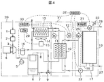
本発明の油冷式ガス圧縮機における排熱回収システムの実施例2を図4に示す系統図により説明する。この図4において、上記図1と同一符号を付した部分は同一或いは相当する部分であるので、図1に示す実施例1と異なる部分を中心に説明する。 Embodiment 2 of the exhaust heat recovery system in the oil-cooled gas compressor of the present invention will be described with reference to the system diagram shown in FIG. In FIG. 4, the parts denoted by the same reference numerals as those in FIG. 1 are the same or corresponding parts, and therefore, different parts from the first embodiment shown in FIG. 1 will be mainly described.
上記実施例1では、貯温水タンク19内に水対水熱交換器24を設け、循環回路17,18を循環する熱媒体を、前記水対水熱交換器24に通過させ、前記貯温水タンク19内の水(温水)と熱交換させるようにした例について説明した。
これに対し、本実施例2では、図1に示す上記水対水熱交換器24を設けず、前記循環回路17,18を循環させる熱媒体を、貯温水タンク19内の水(水とは温水である場合も含む)にしていることが異なっている。
In the first embodiment, the water-to-
On the other hand, in the second embodiment, the water-to-
即ち、貯温水タンクユニット23の前記貯温水タンク19内の水をその下部から直接熱媒体入口配管17に導き、循環ポンプ22により、排熱回収ユニット21の排熱回収熱交換器(水冷熱交換器)10に送るように構成している。前記排熱回収熱交換器10に送られた前記水(熱媒体)は、該排熱回収熱交換器内の油配管7を流れる高温の油及びガス配管(空気配管)8を流れる高温の圧縮ガスと熱交換されてこれらの油及び圧縮ガスから熱を回収して加熱される。
That is, the water in the hot
水に熱を回収されて冷却された前記油と圧縮ガスは、油配管7またはガス配管8を介して下流側に設置されている空冷熱交換器13に送られて更に冷却されるように構成されている。また、前記排熱回収熱交換器10で加熱されて温度の上昇した前記水(温水)は熱媒体出口配管18を介して、前記貯温水タンク19に戻される。このようにして、前記貯温水タンク19内の水は何度も前記排熱回収熱交換器10へ循環される。従って、貯温水タンク19内の水の温度を次第に上昇させることができる。
The oil and compressed gas cooled by recovering heat in water are sent to an air
これにより、前記貯温水タンク19内の水を予め決めた所定の温度まで上昇させることが可能となる。また、空気圧縮機の負荷率が小さくなった場合でもその負荷率に関係なく要求温度の温水供給が可能となるから、温水の要求下限温度がある場合で、更にその要求温度が圧縮機吐出温度より数度しか低くないような場合であってもその要求温度の温水を供給することが可能になる。
As a result, the water in the
本実施例2のように構成しても上記実施例1と同様の効果が得られる。また、本実施例2では、実施例1に示すような水対水熱交換器を設ける必要がないので、構造が簡単となり安価に製作することができる共に、前記水対水熱交換器による熱交換をさせなくて良い分、排熱回収率を向上させることができる。 Even if it is configured as in the second embodiment, the same effect as in the first embodiment can be obtained. Further, in this second embodiment, it is not necessary to provide a water-to-water heat exchanger as shown in the first embodiment, so that the structure can be simplified and can be manufactured at low cost, and the heat from the water-to-water heat exchanger can be reduced. The waste heat recovery rate can be improved by the amount that does not require replacement.
また、貯温水タンク19内の最下部から水を導いて排熱回収熱交換器10で熱交換させることができるから、貯温水タンク19内の最も低い温度の水と圧縮機からの高温の油と圧縮ガスとを熱交換させるので、排熱回収率を更に向上することもできる。
他の構成や制御については上記実施例1と同様であるので、説明を省略する。
Further, since water can be introduced from the lowermost part of the
Since other configurations and controls are the same as those in the first embodiment, description thereof will be omitted.
以上説明したように、本発明の各実施例によれば、ガス配管8を流れる圧縮ガスと油配管7を流れる油の少なくとも何れかから熱回収するための排熱回収熱交換器10を備え、更に、この排熱回収熱交換器10で受け取った熱を温水として貯える貯温水タンク19と、前記排熱回収熱交換器10で受け取った熱を前記貯温水タンク19に移動させるために、熱媒体(水などの流体)を前記排熱回収熱交換器10と前記貯温水タンク19との間に循環させる循環回路(循環配管17,18)と、この循環回路に設けられた循環用ポンプ22と、前記排熱回収熱交換器で熱交換される油または圧縮ガスの温度が前記貯温水タンク内の温水温度以下の場合に、前記循環用ポンプを停止させるかその回転数を低下させるように制御する制御装置を備えている。
As described above, according to each embodiment of the present invention, the exhaust heat
従って、圧縮機負荷率が低い場合でも要求温度の温水を供給することが可能であり、しかも排熱回収機器からの放熱を抑制して排熱回収率を向上することのできる油冷式ガス圧縮機における排熱回収システムを得ることができる。 Therefore, even when the compressor load factor is low, it is possible to supply hot water at the required temperature, and oil-cooled gas compression that can improve the exhaust heat recovery rate by suppressing heat dissipation from the exhaust heat recovery device An exhaust heat recovery system in the machine can be obtained.
即ち、本実施例では、油冷式ガス圧縮機の冷却系統として、主たる第1の冷却系統である空冷熱交換器13に加えて、第2の冷却系統である排熱回収熱交換器10を備え、更に圧縮機ユニット20に貯温水タンクユニット(排熱回収機器)23を並設して排熱回収システムを構成し、貯温水タンク19と排熱回収熱交換器10の間を、循環配管17,18を介して、熱媒体(上記実施例では水)を何度でも循環させるようにしている。このため、貯温水タンク19内の温水を圧縮機出口温度より数℃だけ低い温度(圧縮機出口温度に近い温度)まで上昇させることが可能になる。
That is, in this embodiment, as the cooling system for the oil-cooled gas compressor, in addition to the air-
油冷式スクリュー圧縮機の出口温度は通常100℃以下と低いので、その排熱により温水を製造する場合、その温度は熱交換器の限界により更に低くなってしまうが、本実施例を採用することにより、圧縮機出口温度に極めて近い温水温度を得ることができる。 Since the outlet temperature of the oil-cooled screw compressor is usually as low as 100 ° C. or lower, when hot water is produced by the exhaust heat, the temperature is further lowered due to the limit of the heat exchanger, but this embodiment is adopted. Thus, a hot water temperature very close to the compressor outlet temperature can be obtained.
また、前記制御装置は、前記排熱回収熱交換器10で熱交換される油または圧縮ガスの温度が前記貯温水タンク19内の温水温度以下の場合に、前記循環用ポンプ22を停止させるかその回転数を低下させるように制御するので、前記循環回路を流れる熱媒体を介して前記貯温水タンク19内の熱が前記排熱回収熱交換器10へ移動して、排熱回収率が悪化するのを抑制することもできる。
Whether the control device stops the
更に、本実施例によれば、前記排熱回収熱交換器10での熱交換量、即ち、前記貯温水タンクユニット(排熱回収機器)23の稼働状況に関係なく、圧縮機ユニット20内の空冷熱交換器13へ送風する冷却ファン14が回転数制御が可能な構成としているので、圧縮機本体3の出口温度が一定の目標温度になるように制御することが可能である。従って、前記貯温水タンクユニット(排熱回収機器)23の稼働状況と圧縮機ユニット20の稼働状況を一致させる必要のない油冷式ガス圧縮機における排熱回収システムを得ることができる。
Furthermore, according to the present embodiment, the amount of heat exchange in the exhaust heat
なお、本発明は上記した実施例に限定されるものではなく、様々な変形例が含まれる。
例えば、上記各実施例では、油冷式ガス圧縮機として油冷式のスクリュー空気圧縮機を例に挙げ説明したが、これには限られず、例えばスクロール圧縮機のような他の方式の圧縮機でも同様に適用できる。
In addition, this invention is not limited to an above-described Example, Various modifications are included.
For example, in each of the above-described embodiments, the oil-cooled screw air compressor has been described as an example of the oil-cooled gas compressor. However, the present invention is not limited to this, and other types of compressors such as a scroll compressor, for example. But it is equally applicable.
また、油冷式ガス圧縮機で圧縮される媒体も空気には限られず、他のガスを圧縮する圧縮機でも同様に適用可能である。更に、駆動源もモータ以外の他の駆動源、例えばエンジンやタービンなどでも良い。 The medium compressed by the oil-cooled gas compressor is not limited to air, and can be similarly applied to a compressor that compresses another gas. Furthermore, the drive source may be a drive source other than the motor, such as an engine or a turbine.
また、上述した実施例では、油冷式ガス圧縮機における排熱回収システムを、圧縮機ユニット20、排熱回収ユニット21及び貯温水タンクユニット23の3つのユニットを並列に配置して接続した例で説明したが、前記3つのユニットを一体化して1ユニットにしたり、或いは2ユニットの構成とすることも可能である。
また、上記した実施例は本発明を分かり易く説明するために詳細に説明したものであり、必ずしも説明した全ての構成を備えるものに限定されるものではない。
In the above-described embodiment, the exhaust heat recovery system in the oil-cooled gas compressor is an example in which three units of the
The above-described embodiments have been described in detail for easy understanding of the present invention, and are not necessarily limited to those having all the configurations described.
1:吸込フィルタ、2:吸込絞り弁、3:圧縮機本体、4:主モータ、
5:吐出温度センサ(圧縮機本体出口温度センサ)、
6:油分離器(オイルタンク)、
7:油配管、8:ガス配管(空気配管)、
9:温調弁、
10:排熱回収熱交換器(水冷熱交換器)
11:温度センサ(ガス温度センサ)(TA)、
12:温度センサ(油温度センサ)(TO)、
13:空冷熱交換器、14:冷却ファン、15:ファンモータ、
16:オイルフィルタ、
17,18:循環配管(循環回路)(17:熱媒体入口配管、18:熱媒体出口配管)、
19:貯温水タンク、
20:圧縮機ユニット、21:排熱回収ユニット、
22:循環ポンプ、
23:貯温水タンクユニット(排熱回収機器)、
24:水対水熱交換器、
25:温度センサ(熱媒体温度センサ)(Tw1)、
26:温度センサ(温水温度センサ)(Tw2)、
27:水入口配管、28:温水出口配管、
29:インバータ、
30〜32:制御装置。
1: Suction filter, 2: Suction throttle valve, 3: Compressor body, 4: Main motor,
5: Discharge temperature sensor (compressor body outlet temperature sensor),
6: Oil separator (oil tank),
7: Oil piping, 8: Gas piping (air piping),
9: Temperature control valve,
10: Waste heat recovery heat exchanger (water-cooled heat exchanger)
11: Temperature sensor (gas temperature sensor) (TA),
12: Temperature sensor (oil temperature sensor) (TO),
13: Air-cooled heat exchanger, 14: Cooling fan, 15: Fan motor,
16: Oil filter,
17, 18: Circulation pipe (circulation circuit) (17: Heat medium inlet pipe, 18: Heat medium outlet pipe),
19: Hot water tank
20: Compressor unit, 21: Waste heat recovery unit,
22: Circulation pump,
23: Hot water tank unit (exhaust heat recovery equipment),
24: Water-to-water heat exchanger,
25: Temperature sensor (heat medium temperature sensor) (Tw1),
26: Temperature sensor (warm water temperature sensor) (Tw2),
27: Water inlet piping, 28: Hot water outlet piping,
29: Inverter
30-32: Control device.
Claims (9)
前記排熱回収熱交換器で受け取った熱を温水として貯える貯温水タンクと、
前記排熱回収熱交換器で受け取った熱を前記貯温水タンクに移動させるために、熱媒体を前記排熱回収熱交換器と前記貯温水タンクとの間に循環させる循環回路と、
この循環回路に設けられた循環用ポンプと、
前記排熱回収熱交換器で熱交換される前記油または前記圧縮ガスの温度が前記貯温水タンク内の温水温度以下の場合に、前記循環用ポンプを停止させるかその回転数を低下させるように制御する制御装置を備える
ことを特徴とする油冷式ガス圧縮機における排熱回収システム。 A compressor body, an oil separator for separating oil from the compressed gas discharged from the compressor body, a gas pipe for sending the compressed gas separated by the oil separator to a customer, and the oil An oil pipe for returning the oil separated by the separator to the compressor main body, and an exhaust heat recovery heat exchanger for recovering heat from at least one of the compressed gas flowing through the gas pipe and the oil flowing through the oil pipe An exhaust heat recovery system in an oil-cooled gas compressor comprising:
A hot water storage tank for storing the heat received by the exhaust heat recovery heat exchanger as hot water;
A circulation circuit for circulating a heat medium between the exhaust heat recovery heat exchanger and the hot water tank in order to move the heat received by the exhaust heat recovery heat exchanger to the hot water tank;
A circulation pump provided in the circulation circuit;
When the temperature of the oil or the compressed gas that is heat-exchanged in the exhaust heat recovery heat exchanger is equal to or lower than the hot water temperature in the hot water tank, the circulation pump is stopped or its rotational speed is reduced. An exhaust heat recovery system for an oil-cooled gas compressor, characterized by comprising a control device for controlling.
前記貯温水タンク内の温水温度を検出するための温水温度センサを備え、前記制御装置は、前記排熱回収熱交換器で熱交換される前記油または前記圧縮ガスの温度が、前記温水温度センサで検出された貯温水タンク内の温水温度以下の場合に、前記循環用ポンプを停止させるかその回転数を低下させる
ことを特徴とする油冷式ガス圧縮機における排熱回収システム。 An exhaust heat recovery system for an oil-cooled gas compressor according to claim 1,
A hot water temperature sensor for detecting a hot water temperature in the hot water tank is provided, and the control device detects whether the temperature of the oil or the compressed gas to be heat exchanged in the exhaust heat recovery heat exchanger is the hot water temperature sensor. The exhaust heat recovery system in an oil-cooled gas compressor, wherein the circulating pump is stopped or its rotation speed is reduced when the temperature is equal to or lower than the temperature of the hot water in the hot water tank detected in step (1).
前記排熱回収熱交換器と前記貯温水タンク間の循環回路の熱媒体温度を検出する熱媒体温度センサを備え、前記制御装置は、前記排熱回収熱交換器で熱交換される前記油または前記圧縮ガスの温度が、前記熱媒体温度センサで検出された温度以下の場合に、前記循環用ポンプを停止させるかその回転数を低下させる
ことを特徴とする油冷式ガス圧縮機における排熱回収システム。 An exhaust heat recovery system for an oil-cooled gas compressor according to claim 1,
A heat medium temperature sensor for detecting a heat medium temperature in a circulation circuit between the exhaust heat recovery heat exchanger and the hot water tank, and the control device is configured to exchange the oil or the heat exchanged by the exhaust heat recovery heat exchanger When the temperature of the compressed gas is equal to or lower than the temperature detected by the heat medium temperature sensor, the circulating pump is stopped or its rotational speed is reduced. Waste heat in an oil-cooled gas compressor, Collection system.
前記圧縮機本体の吐出側温度を検出する吐出温度センサ、前記排熱回収熱交換器の出口側の前記油温度を検出する油温度センサ、前記排熱回収熱交換器の出口側の前記圧縮ガスの温度を検出するガス温度センサの少なくとも何れかを備え、これら吐出温度センサ、油温度センサ、ガス温度センサの少なくとも何れかで検出された温度が、前記温水温度センサまたは前記熱媒体温度センサの何れかで検出された温度以下の場合に、前記循環用ポンプを停止させるかその回転数を低下させる
ことを特徴とする油冷式ガス圧縮機における排熱回収システム。 An exhaust heat recovery system for an oil-cooled gas compressor according to claim 2,
A discharge temperature sensor for detecting the discharge side temperature of the compressor body, an oil temperature sensor for detecting the oil temperature on the outlet side of the exhaust heat recovery heat exchanger, and the compressed gas on the outlet side of the exhaust heat recovery heat exchanger The temperature detected by at least one of the discharge temperature sensor, the oil temperature sensor, and the gas temperature sensor is either the hot water temperature sensor or the heat medium temperature sensor. The exhaust heat recovery system in an oil-cooled gas compressor is characterized in that the circulation pump is stopped or its rotational speed is reduced when the temperature is equal to or lower than the temperature detected in the above.
前記圧縮機本体の吐出側温度を検出する吐出温度センサを備えると共に、前記排熱回収熱交換器の出口側の前記油温度を検出する油温度センサまたは前記排熱回収熱交換器の出口側の前記圧縮ガスの温度を検出するガス温度センサの少なくとも何れかを備え、
前記吐出温度センサで検出された温度が、前記油温度センサまたはガス温度センサの少なくとも何れかで検出された温度よりも低い場合、前記制御装置は、前記排熱回収熱交換器で熱交換される前記油または前記圧縮ガスの温度が前記貯温水タンク内の温水温度以下になっていると判定して、前記循環用ポンプを停止させるかその回転数を低下させる
ことを特徴とする油冷式ガス圧縮機における排熱回収システム。 An exhaust heat recovery system for an oil-cooled gas compressor according to claim 1,
A discharge temperature sensor for detecting a discharge side temperature of the compressor body, and an oil temperature sensor for detecting the oil temperature on the outlet side of the exhaust heat recovery heat exchanger or an outlet side of the exhaust heat recovery heat exchanger Comprising at least one of gas temperature sensors for detecting the temperature of the compressed gas,
When the temperature detected by the discharge temperature sensor is lower than the temperature detected by at least one of the oil temperature sensor and the gas temperature sensor, the control device exchanges heat with the exhaust heat recovery heat exchanger. It is determined that the temperature of the oil or the compressed gas is equal to or lower than the temperature of the hot water in the hot water tank, and the circulating pump is stopped or its rotational speed is reduced. Waste heat recovery system for compressors.
前記貯温水タンク内に水対水熱交換器を設け、前記循環回路の熱媒体を前記水対水熱交換器に通過させて貯温水タンク内の水(温水)と熱交換させるように構成していることを特徴とする油冷式ガス圧縮機における排熱回収システム。 An exhaust heat recovery system for an oil-cooled gas compressor according to claim 1,
A water-to-water heat exchanger is provided in the hot water tank, and the heat medium in the circulation circuit is passed through the water-to-water heat exchanger to exchange heat with water (hot water) in the hot water tank. An exhaust heat recovery system for an oil-cooled gas compressor.
前記循環回路を循環させる熱媒体は前記貯温水タンク内の水(温水)であることを特徴とする油冷式ガス圧縮機における排熱回収システム。 An exhaust heat recovery system for an oil-cooled gas compressor according to claim 1,
An exhaust heat recovery system for an oil-cooled gas compressor, wherein the heat medium circulating in the circulation circuit is water (hot water) in the hot water storage tank.
前記貯温水タンク内の温水温度を検出するための温水温度センサを備え、前記制御装置は、前記温水温度センサで検出された貯温水タンク内の温水温度が、所定温度(要求最低温度)以上になると、供給先への温水供給が可能になるように構成されていることを特徴とする油冷式ガス圧縮機における排熱回収システム。 An exhaust heat recovery system for an oil-cooled gas compressor according to claim 1,
A hot water temperature sensor for detecting a hot water temperature in the hot water tank is provided, and the control device detects that the hot water temperature in the hot water tank detected by the hot water temperature sensor is equal to or higher than a predetermined temperature (required minimum temperature). In this case, the exhaust heat recovery system in the oil-cooled gas compressor is configured so that hot water can be supplied to the supply destination.
前記排熱回収熱交換器の下流側に設けられ、前記ガス配管を流れる圧縮ガスと前記油配管を流れる潤滑油を冷却するための空冷熱交換器と、この空冷熱交換器に冷却風を送る冷却ファンを備え、
前記冷却ファンは前記圧縮機本体から吐出される圧縮ガスの温度が所定の範囲になるように回転数制御される
ことを特徴とする油冷式ガス圧縮機における排熱回収システム。 An exhaust heat recovery system for an oil-cooled gas compressor according to claim 1,
An air-cooled heat exchanger provided on the downstream side of the exhaust heat recovery heat exchanger for cooling the compressed gas flowing through the gas pipe and the lubricating oil flowing through the oil pipe, and sends cooling air to the air-cooled heat exchanger With cooling fan,
The exhaust heat recovery system in an oil-cooled gas compressor, wherein the cooling fan is controlled in rotation speed so that the temperature of the compressed gas discharged from the compressor main body falls within a predetermined range.
Priority Applications (15)
| Application Number | Priority Date | Filing Date | Title |
|---|---|---|---|
| JP2013013358A JP5985405B2 (en) | 2013-01-28 | 2013-01-28 | Waste heat recovery system for oil-cooled gas compressor |
| TR2019/03912T TR201903912T4 (en) | 2013-01-28 | 2014-01-15 | Waste heat recovery system in oil cooled gas compressor. |
| ES19156289T ES2863456T3 (en) | 2013-01-28 | 2014-01-15 | Oil-cooled gas compressor waste heat recovery system |
| US14/763,358 US10041698B2 (en) | 2013-01-28 | 2014-01-15 | Waste-heat recovery system in oil-cooled gas compressor |
| EP21157494.2A EP3842636B8 (en) | 2013-01-28 | 2014-01-15 | Waste-heat recovery system in oil-cooled gas compressor |
| EP19156289.1A EP3499037B2 (en) | 2013-01-28 | 2014-01-15 | Waste-heat recovery system in oil-cooled gas compressor |
| EP14743578.8A EP2949939B1 (en) | 2013-01-28 | 2014-01-15 | Waste-heat recovery system in oil-cooled gas compressor |
| PL19156289.1T PL3499037T5 (en) | 2013-01-28 | 2014-01-15 | Waste-heat recovery system in oil-cooled gas compressor |
| PL21157494.2T PL3842636T3 (en) | 2013-01-28 | 2014-01-15 | Waste-heat recovery system in oil-cooled gas compressor |
| ES21157494T ES2927692T3 (en) | 2013-01-28 | 2014-01-15 | Waste heat recovery system in oil-cooled gas compressor |
| PCT/JP2014/050548 WO2014115616A1 (en) | 2013-01-28 | 2014-01-15 | Waste-heat recovery system in oil-cooled gas compressor |
| CN201480006338.6A CN104968942B (en) | 2013-01-28 | 2014-01-15 | The residual neat recovering system of oil injection type gas compressor |
| US16/032,554 US10578339B2 (en) | 2013-01-28 | 2018-07-11 | Waste-heat recovery system in oil-cooled gas compressor |
| US16/748,062 US11300322B2 (en) | 2013-01-28 | 2020-01-21 | Waste-heat recovery system in oil-cooled gas compressor |
| US17/674,909 US11821657B2 (en) | 2013-01-28 | 2022-02-18 | Waste-heat recovery system in oil-cooled gas compressor |
Applications Claiming Priority (1)
| Application Number | Priority Date | Filing Date | Title |
|---|---|---|---|
| JP2013013358A JP5985405B2 (en) | 2013-01-28 | 2013-01-28 | Waste heat recovery system for oil-cooled gas compressor |
Related Child Applications (1)
| Application Number | Title | Priority Date | Filing Date |
|---|---|---|---|
| JP2016152635A Division JP6533196B2 (en) | 2016-08-03 | 2016-08-03 | Gas compressor |
Publications (2)
| Publication Number | Publication Date |
|---|---|
| JP2014145273A JP2014145273A (en) | 2014-08-14 |
| JP5985405B2 true JP5985405B2 (en) | 2016-09-06 |
Family
ID=51227408
Family Applications (1)
| Application Number | Title | Priority Date | Filing Date |
|---|---|---|---|
| JP2013013358A Active JP5985405B2 (en) | 2013-01-28 | 2013-01-28 | Waste heat recovery system for oil-cooled gas compressor |
Country Status (8)
| Country | Link |
|---|---|
| US (2) | US10041698B2 (en) |
| EP (3) | EP2949939B1 (en) |
| JP (1) | JP5985405B2 (en) |
| CN (1) | CN104968942B (en) |
| ES (2) | ES2863456T3 (en) |
| PL (2) | PL3499037T5 (en) |
| TR (1) | TR201903912T4 (en) |
| WO (1) | WO2014115616A1 (en) |
Families Citing this family (16)
| Publication number | Priority date | Publication date | Assignee | Title |
|---|---|---|---|---|
| JP6607960B2 (en) * | 2015-12-25 | 2019-11-20 | 株式会社日立産機システム | Gas compressor |
| JP6741196B2 (en) * | 2016-08-08 | 2020-08-19 | 三浦工業株式会社 | Air compression system |
| JP6833172B2 (en) * | 2016-08-08 | 2021-02-24 | 三浦工業株式会社 | Heat recovery system |
| EP3315780B2 (en) | 2016-10-28 | 2021-11-24 | ALMiG Kompressoren GmbH | Oil-injected screw air compressor |
| CN106931641A (en) * | 2017-03-27 | 2017-07-07 | 湖南创化低碳环保科技有限公司 | Directly-heated type Teat pump boiler |
| WO2018179789A1 (en) * | 2017-03-31 | 2018-10-04 | 株式会社日立産機システム | Gas compressor |
| CN107939645A (en) * | 2017-12-13 | 2018-04-20 | 宁波勋辉电器有限公司 | Air compressor machine heat reclamation device control system |
| JP7302460B2 (en) * | 2019-12-02 | 2023-07-04 | 三浦工業株式会社 | air compression system |
| DE102020115300A1 (en) * | 2020-06-09 | 2021-12-09 | Knorr-Bremse Systeme für Schienenfahrzeuge GmbH | Compressor system and method for controlling a cooling device of a compressor system |
| JP7282720B2 (en) | 2020-08-13 | 2023-05-29 | 株式会社日立産機システム | LIQUID-COOLED GAS COMPRESSOR AND PREHEATING CONTROL METHOD THEREOF |
| CN113449977B (en) * | 2021-06-23 | 2022-02-22 | 广东鑫钻节能科技股份有限公司 | Heat recycling system of air compression station |
| BE1029818B1 (en) * | 2021-10-04 | 2023-05-03 | Atlas Copco Airpower Nv | Air-cooled device and method for controlling an air-cooled device |
| PL440055A1 (en) * | 2021-12-31 | 2023-07-03 | Asfi Spółka Z Ograniczoną Odpowiedzialnością | System and method of recovery of waste thermal energy contained in oil in an oil-cooled air compressor |
| JP2023129975A (en) * | 2022-03-07 | 2023-09-20 | 株式会社日立産機システム | gas compressor |
| CN114876768B (en) * | 2022-06-21 | 2023-04-07 | 华海(北京)科技股份有限公司 | Waste heat recovery type energy-saving compressor |
| BE1030667B1 (en) * | 2022-06-28 | 2024-01-30 | Atlas Copco Airpower Nv | Cooling device and method for recovering waste heat from a pumping device for compressing gas flow |
Family Cites Families (43)
| Publication number | Priority date | Publication date | Assignee | Title |
|---|---|---|---|---|
| US3856493A (en) * | 1973-05-08 | 1974-12-24 | Dunham Bush Inc | Energy recovery system for oil injected screw compressors |
| US4238931A (en) * | 1979-01-25 | 1980-12-16 | Energy Conservation Unlimited, Inc. | Waste heat recovery system controller |
| JPS56165912U (en) | 1980-05-13 | 1981-12-09 | ||
| JPS5867981A (en) * | 1981-10-16 | 1983-04-22 | Hitachi Ltd | Discharge heat recovery unit of compressor |
| JPS6021880U (en) | 1983-07-23 | 1985-02-15 | 大和興業株式会社 | Waste heat utilization equipment |
| JPH0424157Y2 (en) * | 1985-04-30 | 1992-06-05 | ||
| JPS62258952A (en) * | 1986-04-11 | 1987-11-11 | Daikin Ind Ltd | Temperature regulator for bath |
| JPH083889Y2 (en) | 1989-11-01 | 1996-01-31 | ダイキン工業株式会社 | Cooling water heater |
| US5440894A (en) | 1993-05-05 | 1995-08-15 | Hussmann Corporation | Strategic modular commercial refrigeration |
| US6347528B1 (en) * | 1999-07-26 | 2002-02-19 | Denso Corporation | Refrigeration-cycle device |
| JP2001255002A (en) * | 2000-03-09 | 2001-09-21 | Tokyo Gas Co Ltd | Water heater |
| US6644400B2 (en) * | 2001-10-11 | 2003-11-11 | Abi Technology, Inc. | Backwash oil and gas production |
| JP3968632B2 (en) * | 2001-12-07 | 2007-08-29 | 矢崎総業株式会社 | Liquefied gas supply device |
| NO323437B1 (en) | 2004-08-30 | 2007-05-07 | Terje Engervik | Air pre-treatment plant |
| JP2006125302A (en) * | 2004-10-29 | 2006-05-18 | Hitachi Industrial Equipment Systems Co Ltd | Oil-free screw compressor |
| JP2006250523A (en) * | 2005-02-14 | 2006-09-21 | Osaka Gas Co Ltd | Hot water heat source hot water supply system, hot water heat source hot water supply device and hot water heat source hot water supply method |
| GB0510892D0 (en) * | 2005-05-27 | 2005-07-06 | Boc Group Plc | Vacuum pump |
| JP2007271211A (en) * | 2006-03-31 | 2007-10-18 | Daikin Ind Ltd | Refrigerating device |
| US20080127665A1 (en) * | 2006-11-30 | 2008-06-05 | Husky Injection Molding Systems Ltd. | Compressor |
| KR100779107B1 (en) * | 2006-12-08 | 2007-11-27 | 한국전자통신연구원 | Apparatus and method for determining the timing of user equipment's initial ranging using rangings of other ues over mmr system |
| JP5110882B2 (en) | 2007-01-05 | 2012-12-26 | 株式会社日立産機システム | Oil-free screw compressor |
| DE202007011546U1 (en) | 2007-08-17 | 2009-01-02 | Kroll, Markus | Tempering device based on heat pumps |
| JP5268317B2 (en) * | 2007-09-28 | 2013-08-21 | 株式会社日立産機システム | Oil-cooled air compressor |
| JP5084460B2 (en) * | 2007-11-16 | 2012-11-28 | 株式会社日立産機システム | Oil-cooled air compressor |
| JP4329875B1 (en) | 2008-06-05 | 2009-09-09 | 三浦工業株式会社 | Steam system |
| JP5223526B2 (en) * | 2008-07-31 | 2013-06-26 | 三浦工業株式会社 | Boiler water supply system |
| US8590324B2 (en) | 2009-05-15 | 2013-11-26 | Emerson Climate Technologies, Inc. | Compressor and oil-cooling system |
| JP5495293B2 (en) * | 2009-07-06 | 2014-05-21 | 株式会社日立産機システム | Compressor |
| JP5502459B2 (en) | 2009-12-25 | 2014-05-28 | 三洋電機株式会社 | Refrigeration equipment |
| EP2339265B1 (en) | 2009-12-25 | 2018-03-28 | Sanyo Electric Co., Ltd. | Refrigerating apparatus |
| JP5598724B2 (en) | 2010-04-01 | 2014-10-01 | 三浦工業株式会社 | Compression heat recovery system |
| JP5816422B2 (en) | 2010-08-27 | 2015-11-18 | 日立アプライアンス株式会社 | Waste heat utilization system of refrigeration equipment |
| EP2610495B1 (en) * | 2010-08-27 | 2018-03-07 | Hitachi Industrial Equipment Systems Co., Ltd. | Oil-cooled gas compressor |
| AU2011320032B2 (en) | 2010-10-29 | 2016-11-03 | Kenneth John Tucker | Heating apparatus |
| JP5821235B2 (en) | 2011-03-30 | 2015-11-24 | 三浦工業株式会社 | Liquid cooling system |
| JP5724536B2 (en) | 2011-03-30 | 2015-05-27 | 三浦工業株式会社 | Compressor unit |
| DE102011017433C5 (en) | 2011-04-18 | 2018-02-15 | Compair Drucklufttechnik Zweigniederlassung Der Gardner Denver Deutschland Gmbh | Method for the intelligent control of a compressor system with heat recovery |
| JP5187420B2 (en) | 2011-08-10 | 2013-04-24 | パナソニック株式会社 | Water filling method for fuel cell system |
| JP5885439B2 (en) * | 2011-09-16 | 2016-03-15 | アネスト岩田株式会社 | Waste heat utilization equipment for air compressor |
| CN202402252U (en) | 2011-12-08 | 2012-08-29 | 亿和精密工业(苏州)有限公司 | Waste heat recycling system of air compressor |
| CN202579188U (en) | 2012-03-30 | 2012-12-05 | 东莞市雅迪勤压缩机制造有限公司 | Oil-spraying screw air compressor capable of recovering excess heat |
| JP5568591B2 (en) | 2012-05-11 | 2014-08-06 | 株式会社日立産機システム | Oil-free screw compressor |
| US10746177B2 (en) * | 2014-12-31 | 2020-08-18 | Ingersoll-Rand Industrial U.S., Inc. | Compressor with a closed loop water cooling system |
-
2013
- 2013-01-28 JP JP2013013358A patent/JP5985405B2/en active Active
-
2014
- 2014-01-15 PL PL19156289.1T patent/PL3499037T5/en unknown
- 2014-01-15 TR TR2019/03912T patent/TR201903912T4/en unknown
- 2014-01-15 EP EP14743578.8A patent/EP2949939B1/en active Active
- 2014-01-15 CN CN201480006338.6A patent/CN104968942B/en active Active
- 2014-01-15 ES ES19156289T patent/ES2863456T3/en active Active
- 2014-01-15 WO PCT/JP2014/050548 patent/WO2014115616A1/en active Application Filing
- 2014-01-15 EP EP21157494.2A patent/EP3842636B8/en active Active
- 2014-01-15 PL PL21157494.2T patent/PL3842636T3/en unknown
- 2014-01-15 US US14/763,358 patent/US10041698B2/en active Active
- 2014-01-15 ES ES21157494T patent/ES2927692T3/en active Active
- 2014-01-15 EP EP19156289.1A patent/EP3499037B2/en active Active
-
2020
- 2020-01-21 US US16/748,062 patent/US11300322B2/en active Active
Also Published As
| Publication number | Publication date |
|---|---|
| ES2863456T3 (en) | 2021-10-11 |
| EP2949939A4 (en) | 2016-09-14 |
| JP2014145273A (en) | 2014-08-14 |
| EP3842636B1 (en) | 2022-09-07 |
| CN104968942B (en) | 2017-08-25 |
| WO2014115616A1 (en) | 2014-07-31 |
| US20150362212A1 (en) | 2015-12-17 |
| US10041698B2 (en) | 2018-08-07 |
| PL3842636T3 (en) | 2023-02-20 |
| EP3842636B8 (en) | 2022-10-12 |
| US20200158377A1 (en) | 2020-05-21 |
| PL3499037T5 (en) | 2024-03-04 |
| ES2927692T3 (en) | 2022-11-10 |
| TR201903912T4 (en) | 2019-04-22 |
| EP2949939A1 (en) | 2015-12-02 |
| US11300322B2 (en) | 2022-04-12 |
| EP3842636A1 (en) | 2021-06-30 |
| CN104968942A (en) | 2015-10-07 |
| EP3499037A1 (en) | 2019-06-19 |
| EP2949939B1 (en) | 2019-03-13 |
| EP3499037B1 (en) | 2021-03-03 |
| EP3499037B2 (en) | 2023-12-13 |
| PL3499037T3 (en) | 2021-10-18 |
Similar Documents
| Publication | Publication Date | Title |
|---|---|---|
| JP5985405B2 (en) | Waste heat recovery system for oil-cooled gas compressor | |
| US11821657B2 (en) | Waste-heat recovery system in oil-cooled gas compressor | |
| KR101878763B1 (en) | Heat recovery system | |
| JP5851148B2 (en) | Oil-cooled air compressor | |
| JP5063486B2 (en) | Heat pump hot water heating system | |
| JP6571491B2 (en) | heat pump | |
| CN111503910B (en) | Method for operating a cooler | |
| US10794278B2 (en) | Compressed air storage power generation device | |
| US11686511B2 (en) | Motor temperature control technique with temperature override | |
| JP7050132B2 (en) | Waste heat recovery system | |
| JP6826155B2 (en) | Exhaust heat recovery system | |
| JP6533196B2 (en) | Gas compressor | |
| WO2018193768A1 (en) | Compressed-air storage power generation device | |
| JP5563521B2 (en) | Geothermal heat pump device | |
| WO2018193769A1 (en) | Compressed-air storage power generation device | |
| CN111742185B (en) | Capacity control technique using motor temperature override | |
| JP2019174105A (en) | heat pump |
Legal Events
| Date | Code | Title | Description |
|---|---|---|---|
| RD02 | Notification of acceptance of power of attorney |
Free format text: JAPANESE INTERMEDIATE CODE: A7422 Effective date: 20141027 |
|
| A621 | Written request for application examination |
Free format text: JAPANESE INTERMEDIATE CODE: A621 Effective date: 20150702 |
|
| TRDD | Decision of grant or rejection written | ||
| A01 | Written decision to grant a patent or to grant a registration (utility model) |
Free format text: JAPANESE INTERMEDIATE CODE: A01 Effective date: 20160705 |
|
| A61 | First payment of annual fees (during grant procedure) |
Free format text: JAPANESE INTERMEDIATE CODE: A61 Effective date: 20160803 |
|
| R150 | Certificate of patent or registration of utility model |
Ref document number: 5985405 Country of ref document: JP Free format text: JAPANESE INTERMEDIATE CODE: R150 |