JP5983765B2 - Controller, control method and control program - Google Patents
Controller, control method and control program Download PDFInfo
- Publication number
- JP5983765B2 JP5983765B2 JP2014551009A JP2014551009A JP5983765B2 JP 5983765 B2 JP5983765 B2 JP 5983765B2 JP 2014551009 A JP2014551009 A JP 2014551009A JP 2014551009 A JP2014551009 A JP 2014551009A JP 5983765 B2 JP5983765 B2 JP 5983765B2
- Authority
- JP
- Japan
- Prior art keywords
- manipulated variable
- control
- change
- cooling
- operation amount
- Prior art date
- Legal status (The legal status is an assumption and is not a legal conclusion. Google has not performed a legal analysis and makes no representation as to the accuracy of the status listed.)
- Active
Links
Images


Classifications
-
- G—PHYSICS
- G05—CONTROLLING; REGULATING
- G05B—CONTROL OR REGULATING SYSTEMS IN GENERAL; FUNCTIONAL ELEMENTS OF SUCH SYSTEMS; MONITORING OR TESTING ARRANGEMENTS FOR SUCH SYSTEMS OR ELEMENTS
- G05B11/00—Automatic controllers
- G05B11/01—Automatic controllers electric
- G05B11/36—Automatic controllers electric with provision for obtaining particular characteristics, e.g. proportional, integral, differential
- G05B11/42—Automatic controllers electric with provision for obtaining particular characteristics, e.g. proportional, integral, differential for obtaining a characteristic which is both proportional and time-dependent, e.g. P.I., P.I.D.
-
- G—PHYSICS
- G05—CONTROLLING; REGULATING
- G05B—CONTROL OR REGULATING SYSTEMS IN GENERAL; FUNCTIONAL ELEMENTS OF SUCH SYSTEMS; MONITORING OR TESTING ARRANGEMENTS FOR SUCH SYSTEMS OR ELEMENTS
- G05B13/00—Adaptive control systems, i.e. systems automatically adjusting themselves to have a performance which is optimum according to some preassigned criterion
- G05B13/02—Adaptive control systems, i.e. systems automatically adjusting themselves to have a performance which is optimum according to some preassigned criterion electric
- G05B13/0205—Adaptive control systems, i.e. systems automatically adjusting themselves to have a performance which is optimum according to some preassigned criterion electric not using a model or a simulator of the controlled system
- G05B13/024—Adaptive control systems, i.e. systems automatically adjusting themselves to have a performance which is optimum according to some preassigned criterion electric not using a model or a simulator of the controlled system in which a parameter or coefficient is automatically adjusted to optimise the performance
-
- G—PHYSICS
- G05—CONTROLLING; REGULATING
- G05D—SYSTEMS FOR CONTROLLING OR REGULATING NON-ELECTRIC VARIABLES
- G05D23/00—Control of temperature
- G05D23/19—Control of temperature characterised by the use of electric means
- G05D23/1919—Control of temperature characterised by the use of electric means characterised by the type of controller
-
- G—PHYSICS
- G05—CONTROLLING; REGULATING
- G05B—CONTROL OR REGULATING SYSTEMS IN GENERAL; FUNCTIONAL ELEMENTS OF SUCH SYSTEMS; MONITORING OR TESTING ARRANGEMENTS FOR SUCH SYSTEMS OR ELEMENTS
- G05B2219/00—Program-control systems
- G05B2219/30—Nc systems
- G05B2219/37—Measurements
- G05B2219/37612—Transfer function, kinematic identification, parameter estimation, response
-
- G—PHYSICS
- G05—CONTROLLING; REGULATING
- G05B—CONTROL OR REGULATING SYSTEMS IN GENERAL; FUNCTIONAL ELEMENTS OF SUCH SYSTEMS; MONITORING OR TESTING ARRANGEMENTS FOR SUCH SYSTEMS OR ELEMENTS
- G05B2219/00—Program-control systems
- G05B2219/30—Nc systems
- G05B2219/42—Servomotor, servo controller kind till VSS
- G05B2219/42152—Learn, self, auto tuning, calibrating, environment adaptation, repetition
Description
本発明は、オートチューニング機能を有する調節器、その調節器における制御方法、およびその調節器を実現する制御プログラムに関する。 The present invention relates to a regulator having an auto-tuning function, a control method for the regulator, and a control program for realizing the regulator.
現在、PID制御系をはじめとするフィードバック制御系は、温度制御、速度制御、位置制御といった様々な用途で利用されている。このようなフィードバック制御系では、目標値の変更に対する応答性や外乱に対する収束性を高めるために、比例ゲイン、積分時間、微分時間といった制御パラメータを制御対象に応じて最適化することが重要である。 Currently, feedback control systems such as PID control systems are used in various applications such as temperature control, speed control, and position control. In such a feedback control system, it is important to optimize control parameters such as proportional gain, integration time, and derivative time according to the object to be controlled in order to improve the responsiveness to the change of the target value and the convergence to the disturbance. .
しかしながら、フィードバック制御系についての知識のないユーザが制御パラメータを最適化することは容易ではない。そのため、このような制御パラメータを自動的に最適化するオートチューニング機能が開発および実用化されている。このようなオートチューニング機能の代表例としては、ステップ応答法、限界感度法(非特許文献1参照)、リミットサイクル法(特許文献1および2参照)などが知られている。
However, it is not easy for a user who has no knowledge of the feedback control system to optimize the control parameters. Therefore, an auto tuning function for automatically optimizing such control parameters has been developed and put into practical use. As typical examples of such an auto tuning function, a step response method, a limit sensitivity method (see Non-Patent Document 1), a limit cycle method (see
具体的には、特開平05−289704号公報(特許文献1)は、加熱および冷却2種類のPID演算機能を有する加熱冷却調節計を開示する。この加熱冷却調節計は、加熱および冷却オートチューニング機能を有している。特開2004−227062号公報(特許文献2)は、加熱アクチュエータに操作量を出力するヒートモードと冷却アクチュエータに操作量を出力するクールモードとを適宜切り換えて温度制御を行うヒートクール制御技術を開示している。このヒートクール制御技術は、操作量振幅が一定のリミットサイクルを発生させて制御パラメータを調整するリミットサイクルオートチューニング方法を含む。 Specifically, Japanese Patent Application Laid-Open No. 05-289704 (Patent Document 1) discloses a heating / cooling controller having two types of PID calculation functions of heating and cooling. This heating / cooling controller has heating and cooling auto-tuning functions. Japanese Patent Laying-Open No. 2004-227062 (Patent Document 2) discloses a heat / cool control technique for performing temperature control by appropriately switching between a heat mode for outputting an operation amount to a heating actuator and a cool mode for outputting an operation amount to a cooling actuator. doing. This heat-cool control technique includes a limit cycle auto-tuning method for adjusting a control parameter by generating a limit cycle having a constant operation amount amplitude.
フィードバック制御系に非線形要素を含む場合、つまり、操作量と制御対象に生じる制御量との間の非線形性が強い場合には、オートチューニング機能では制御パラメータを最適化できないこともある。特許文献1に記載の加熱冷却調節計は、非線形の静特性を有する制御対象に対して、冷却オートチューニング時において、制限率を用いて操作量の個々のレベルを制限するという構成を採用する。しかしながら、この制限率をどのような値に決定すべきかについては何ら開示されておらず、制御対象に応じて経験的または試行錯誤的に決定せざるを得ない。また、特許文献2に記載のヒートクール制御装置は、第1のリミットサイクルと第2のリミットサイクルとを発生させ、その制御応答に基づいて制御パラメータを算出するという構成を採用する。しかしながら、この特許文献2に記載の構成は、ヒート側の加熱能力とクール側の冷却能力とに差がある場合を想定しており、加熱能力および/または冷却能力の各々が非線形性を有するような場合には対応できない。
When the feedback control system includes a nonlinear element, that is, when the nonlinearity between the manipulated variable and the controlled variable generated in the controlled object is strong, the auto tuning function may not optimize the control parameter. The heating / cooling controller described in
本発明は、このような課題を解決するためのものであり、その目的は、非線形性の強い制御対象に対しても、オートチューニングを適切に行うことのできる調節器、その調節器における制御方法、およびその調節器を実現する制御プログラムを提供することである。 The present invention is intended to solve such problems, and an object of the present invention is to provide a regulator capable of appropriately performing auto-tuning even for a highly nonlinear control target, and a control method in the regulator. And a control program for realizing the regulator.
本発明の別の目的は、ユーザフレンドリなオートチューニング機能を有する調節器、その調節器における制御方法、およびその調節器を実現する制御プログラムを提供することである。 Another object of the present invention is to provide a regulator having a user-friendly auto-tuning function, a control method for the regulator, and a control program for realizing the regulator.
本発明のある局面に係るオートチューニング機能を有する調節器は、制御対象から取得される観測量が目標値と一致するように、予め設定されたパラメータに従って、制御対象の制御量に第1の変化を生じさせるための第1の操作量、または、制御量に第1の変化とは反対の第2の変化を生じさせるための第2の操作量、を選択的に決定する操作量決定手段と、第1の操作量および第2の操作量を観測量に応じて交互に出力し、当該交互出力によって取得された応答特性からパラメータを決定するチューニング手段とを含む。チューニング手段は、第1の操作量および第2の操作量の交互出力において、出力の切替毎に第1の操作量の大きさを順次変更するとともに、第1の操作量に対する制御量の第1の変化が線形性を有していると判断されたときに取得された応答特性からパラメータを決定する。 A regulator having an auto-tuning function according to an aspect of the present invention has a first change in a control amount of a control target according to a preset parameter so that an observation amount acquired from the control target matches a target value. Manipulated variable determining means for selectively determining a first manipulated variable for generating a second manipulated variable or a second manipulated variable for causing a second change opposite to the first change in the controlled variable; And tuning means for alternately outputting the first manipulated variable and the second manipulated variable in accordance with the observed quantity and determining a parameter from the response characteristics acquired by the alternate output. In the alternate output of the first operation amount and the second operation amount, the tuning means sequentially changes the magnitude of the first operation amount every time the output is switched, and the first control amount with respect to the first operation amount. The parameter is determined from the response characteristic acquired when it is determined that the change in the signal has linearity.
好ましくは、チューニング手段は、直前の交互出力によって取得された応答特性から、新たな交互出力における第1の操作量の大きさを決定する。 Preferably, the tuning means determines the magnitude of the first manipulated variable in the new alternate output from the response characteristic acquired by the previous alternate output.
さらに好ましくは、チューニング手段は、直前の交互出力において第1の操作量が出力された期間の長さと第2の操作量が出力された期間の長さとに応じて、当該直前の交互出力における第1の操作量の大きさを補正することで、新たな交互出力における第1の操作量の大きさを決定する。 More preferably, the tuning means is configured to change the first output in the immediately preceding alternating output according to the length of the period in which the first manipulated variable is output and the length of the period in which the second manipulated variable is output. The magnitude of the first manipulated variable in the new alternate output is determined by correcting the magnitude of the manipulated variable of 1.
好ましくは、チューニング手段は、順次変更される第1の操作量の大きさの別に、第1の操作量に対応する制御量の変化速度との関係を評価することで、第1の操作量に対する制御量の第1の変化が線形性を有しているか否かを判断する。 Preferably, the tuning unit evaluates the relationship with the change rate of the control amount corresponding to the first operation amount, separately from the first operation amount that is sequentially changed, so that the first operation amount is changed. It is determined whether or not the first change in the control amount has linearity.
好ましくは、チューニング手段は、第1の操作量に対する制御量の第1の変化が線形性を有していると判断されなくとも、第1の操作量および第2の操作量の交互出力が予め定められた回数実行されると、最終の交互出力において取得された応答特性からパラメータを決定する。 Preferably, even if the tuning unit does not determine that the first change in the control amount with respect to the first operation amount has linearity, the alternate output of the first operation amount and the second operation amount is performed in advance. When executed a predetermined number of times, the parameters are determined from the response characteristics acquired in the final alternating output.
本発明の別の局面に係るオートチューニング機能を有する調節器は、制御対象から取得される観測量が目標値と一致するように、予め設定されたパラメータに従って、制御対象の制御量に第1の変化を生じさせるための第1の操作量、または、制御量に第1の変化とは反対の第2の変化を生じさせるための第2の操作量、を選択的に決定する操作量決定手段と、第1の操作量および第2の操作量を観測量に応じて交互に出力し、当該交互出力によって取得された応答特性からパラメータを決定するチューニング手段とを含む。チューニング手段は、直前の交互出力における第2の操作量が出力された期間の長さに対する第1の操作量が出力された期間の長さの比のn乗(n>1)に応じて、当該直前の交互出力における第1の操作量の大きさを補正することで、新たな交互出力における第1の操作量の大きさを決定する。 A regulator having an auto-tuning function according to another aspect of the present invention provides a first control amount for a control target according to a preset parameter so that an observation amount acquired from the control target matches a target value. An operation amount determination means for selectively determining a first operation amount for causing a change or a second operation amount for causing a second change in the control amount opposite to the first change. And tuning means for alternately outputting the first manipulated variable and the second manipulated variable in accordance with the observed quantity and determining a parameter from the response characteristic acquired by the alternate output. The tuning means is responsive to the nth power (n> 1) of the ratio of the length of the period during which the first manipulated variable is output to the length of the period during which the second manipulated variable is output in the previous alternate output. The magnitude of the first manipulated variable in the new alternate output is determined by correcting the magnitude of the first manipulated variable in the immediately preceding alternate output.
好ましくは、チューニング手段は、1.5≦n≦3.0を満たすようなnを用いて、新たな交互出力における第1の操作量の大きさを決定する。 Preferably, the tuning means determines the magnitude of the first operation amount in the new alternating output using n that satisfies 1.5 ≦ n ≦ 3.0.
好ましくは、制御対象は、加熱装置および冷却装置を含む押出成形機を含み、加熱装置により制御対象に生じる加熱についての制御量は、対応する操作量について相対的に強い線形性を有しており、冷却装置により制御対象に生じる冷却についての制御量は、対応する操作量について相対的に強い非線形性を有している。 Preferably, the control target includes an extruder including a heating device and a cooling device, and the control amount for heating generated in the control target by the heating device has relatively strong linearity with respect to the corresponding operation amount. The control amount for cooling generated in the controlled object by the cooling device has a relatively strong non-linearity with respect to the corresponding operation amount.
本発明のさらに別の局面に係るオートチューニング機能を有する調節器は、制御対象から取得される観測量が目標値と一致するように、予め設定されたパラメータに従って、制御対象の制御量に第1の変化を生じさせるための第1の操作量、または、制御量に第1の変化とは反対の第2の変化を生じさせるための第2の操作量、を選択的に決定する操作量決定手段と、第1の操作量および第2の操作量を観測量に応じて交互に1回ずつ出力し、第1の操作量および第2の操作量の1回ずつの交互出力によって取得された応答特性からパラメータを決定するチューニング手段とを含む。チューニング手段は、応答特性から第1の操作量に対する制御量の第1の変化が線形性を維持できる第1の操作量の範囲を推定するとともに、当該推定した範囲からパラメータを決定する。 The regulator having an auto-tuning function according to still another aspect of the present invention is configured such that the first controlled variable is controlled according to a preset parameter so that the observed value acquired from the controlled object matches the target value. The operation amount determination for selectively determining the first operation amount for causing the change or the second operation amount for causing the control amount to cause the second change opposite to the first change. The means and the first manipulated variable and the second manipulated variable are alternately output once each according to the observed quantity, and the first manipulated variable and the second manipulated variable are obtained by one-time alternate output. Tuning means for determining a parameter from the response characteristic. The tuning means estimates a range of the first manipulated variable in which the first change of the controlled variable with respect to the first manipulated variable can maintain linearity from the response characteristic, and determines a parameter from the estimated range.
本発明のさらに別の局面に係るオートチューニング機能を有する調節器は、制御対象から取得される観測量が目標値と一致するように、予め設定されたパラメータに従って、制御対象の制御量に第1の変化を生じさせるための第1の操作量、または、制御量に第1の変化とは反対の第2の変化を生じさせるための第2の操作量、を選択的に決定する操作量決定手段と、第1の操作量および第2の操作量を観測量に応じて交互に出力し、当該交互出力によって取得された応答特性からパラメータを決定するチューニング手段と、現在実行されている交互出力の回数を表示する表示手段とを含む。 The regulator having an auto-tuning function according to still another aspect of the present invention is configured such that the first controlled variable is controlled according to a preset parameter so that the observed value acquired from the controlled object matches the target value. The operation amount determination for selectively determining the first operation amount for causing the change or the second operation amount for causing the control amount to cause the second change opposite to the first change. Means, tuning means for alternately outputting the first manipulated variable and the second manipulated variable in accordance with the observed quantity, and determining parameters from the response characteristics obtained by the alternate output, and the alternating output currently being executed Display means for displaying the number of times.
本発明のさらに別の局面に係るオートチューニング機能を有する調節器は、制御対象から取得される観測量が目標値と一致するように、予め設定されたパラメータに従って、制御対象の制御量に第1の変化を生じさせるための第1の操作量、または、制御量に第1の変化とは反対の第2の変化を生じさせるための第2の操作量、を選択的に決定する操作量決定手段と、第1の操作量および第2の操作量を観測量に応じて交互に出力し、当該交互出力によって取得された応答特性からパラメータを決定するチューニング手段と、パラメータの決定に必要な交互出力が完了する時期を表示する表示手段とを含む。 The regulator having an auto-tuning function according to still another aspect of the present invention is configured such that the first controlled variable is controlled according to a preset parameter so that the observed value acquired from the controlled object matches the target value. The operation amount determination for selectively determining the first operation amount for causing the change or the second operation amount for causing the control amount to cause the second change opposite to the first change. Means, tuning means for alternately outputting the first manipulated variable and the second manipulated variable in accordance with the observed quantity, and determining a parameter from the response characteristic obtained by the alternate output, and the alternating necessary for determining the parameter Display means for displaying when the output is completed.
本発明のさらに別の局面に係るオートチューニング機能を有する調節器における制御方法は、制御対象から取得される観測量が目標値と一致するように、予め設定されたパラメータに従って、制御対象の制御量に第1の変化を生じさせるための第1の操作量、または、制御量に第1の変化とは反対の第2の変化を生じさせるための第2の操作量、を選択的に決定するステップと、第1の操作量および第2の操作量を観測量に応じて交互に出力し、当該交互出力によって取得された応答特性からパラメータを決定するステップとを含む。パラメータを決定するステップは、第1の操作量および第2の操作量の交互出力において、出力の切替毎に第1の操作量の大きさを順次変更するとともに、第1の操作量に対する制御量の第1の変化が線形性を有していると判断されたときに取得された応答特性からパラメータを決定するステップを含む。 The control method in the regulator having an auto-tuning function according to still another aspect of the present invention includes a control amount of a control target according to a preset parameter so that an observation amount acquired from the control target matches a target value. The first manipulated variable for causing the first change to be generated or the second manipulated variable for causing the control variable to produce the second change opposite to the first change is selectively determined. And a step of alternately outputting the first manipulated variable and the second manipulated variable according to the observed quantity and determining a parameter from the response characteristic acquired by the alternate output. In the step of determining the parameter, in the alternate output of the first operation amount and the second operation amount, the magnitude of the first operation amount is sequentially changed every time the output is switched, and the control amount with respect to the first operation amount is determined. Determining a parameter from a response characteristic obtained when it is determined that the first change of the first change is linear.
本発明のさらに別の局面に係るオートチューニング機能を有する調節器における制御方法は、制御対象から取得される観測量が目標値と一致するように、予め設定されたパラメータに従って、制御対象の制御量に第1の変化を生じさせるための第1の操作量、または、制御量に第1の変化とは反対の第2の変化を生じさせるための第2の操作量、を選択的に決定するステップと、第1の操作量および第2の操作量を観測量に応じて交互に出力し、当該交互出力によって取得された応答特性からパラメータを決定するステップとを含む。パラメータを決定するステップは、直前の交互出力における第2の操作量が出力された期間の長さに対する第1の操作量が出力された期間の長さの比のn乗(n>1)に応じて、当該直前の交互出力における第1の操作量の大きさを補正することで、新たな交互出力における第1の操作量の大きさを決定するステップを含む。 The control method in the regulator having an auto-tuning function according to still another aspect of the present invention includes a control amount of a control target according to a preset parameter so that an observation amount acquired from the control target matches a target value. The first manipulated variable for causing the first change to be generated or the second manipulated variable for causing the control variable to produce the second change opposite to the first change is selectively determined. And a step of alternately outputting the first manipulated variable and the second manipulated variable according to the observed quantity and determining a parameter from the response characteristic acquired by the alternate output. The step of determining the parameter is the nth power (n> 1) of the ratio of the length of the period in which the first manipulated variable is output to the length of the period in which the second manipulated variable is output in the previous alternate output. Accordingly, the method includes the step of determining the magnitude of the first manipulated variable in the new alternate output by correcting the magnitude of the first manipulated variable in the immediately preceding alternate output.
本発明のさらに別の局面に係るオートチューニング機能を有する調節器における制御方法は、制御対象から取得される観測量が目標値と一致するように、予め設定されたパラメータに従って、制御対象の制御量に第1の変化を生じさせるための第1の操作量、または、制御量に第1の変化とは反対の第2の変化を生じさせるための第2の操作量、を選択的に決定するステップと、第1の操作量および第2の操作量を観測量に応じて交互に1回ずつ出力し、第1の操作量および第2の操作量の1回ずつの交互出力によって取得された応答特性からパラメータを決定するステップとを含む。パラメータを決定するステップは、応答特性から第1の操作量に対する制御量の第1の変化が線形性を維持できる第1の操作量の範囲を推定するとともに、当該推定した範囲からパラメータを決定するステップを含む。 The control method in the regulator having an auto-tuning function according to still another aspect of the present invention includes a control amount of a control target according to a preset parameter so that an observation amount acquired from the control target matches a target value. The first manipulated variable for causing the first change to be generated or the second manipulated variable for causing the control variable to produce the second change opposite to the first change is selectively determined. The step, the first manipulated variable and the second manipulated variable are alternately output once according to the observed quantity, and the first manipulated variable and the second manipulated variable are obtained by one-time alternate output. Determining a parameter from the response characteristic. The step of determining the parameter estimates a range of the first manipulated variable in which the first change of the controlled variable with respect to the first manipulated variable can maintain linearity from the response characteristic, and determines the parameter from the estimated range. Includes steps.
本発明のさらに別の局面に係るオートチューニング機能を有する調節器における制御方法は、制御対象から取得される観測量が目標値と一致するように、予め設定されたパラメータに従って、制御対象の制御量に第1の変化を生じさせるための第1の操作量、または、制御量に第1の変化とは反対の第2の変化を生じさせるための第2の操作量、を選択的に決定するステップと、第1の操作量および第2の操作量を観測量に応じて交互に出力し、当該交互出力によって取得された応答特性からパラメータを決定するステップと、現在実行されている交互出力の回数を表示するステップとを含む。 The control method in the regulator having an auto-tuning function according to still another aspect of the present invention includes a control amount of a control target according to a preset parameter so that an observation amount acquired from the control target matches a target value. The first manipulated variable for causing the first change to be generated or the second manipulated variable for causing the control variable to produce the second change opposite to the first change is selectively determined. A step, a step of alternately outputting the first manipulated variable and the second manipulated variable in accordance with the observed amount, determining a parameter from the response characteristic acquired by the alternate output, and a currently executed alternate output Displaying the number of times.
本発明のさらに別の局面に係るオートチューニング機能を有する調節器における制御方法は、制御対象から取得される観測量が目標値と一致するように、予め設定されたパラメータに従って、制御対象の制御量に第1の変化を生じさせるための第1の操作量、または、制御量に第1の変化とは反対の第2の変化を生じさせるための第2の操作量、を選択的に決定するステップと、第1の操作量および第2の操作量を観測量に応じて交互に出力し、当該交互出力によって取得された応答特性からパラメータを決定するステップと、パラメータの決定に必要な交互出力が完了する時期を表示するステップとを含む。 The control method in the regulator having an auto-tuning function according to still another aspect of the present invention includes a control amount of a control target according to a preset parameter so that an observation amount acquired from the control target matches a target value. The first manipulated variable for causing the first change to be generated or the second manipulated variable for causing the control variable to produce the second change opposite to the first change is selectively determined. A step, a step of alternately outputting the first manipulated variable and the second manipulated variable according to the observed amount, determining a parameter from the response characteristic obtained by the alternate output, and an alternate output necessary for determining the parameter And a step of displaying a time when the is completed.
本発明のさらに別の局面に係るオートチューニング機能を有する調節器を実現する制御プログラムは、プロセッサに、制御対象から取得される観測量が目標値と一致するように、予め設定されたパラメータに従って、制御対象の制御量に第1の変化を生じさせるための第1の操作量、または、制御量に第1の変化とは反対の第2の変化を生じさせるための第2の操作量、を選択的に決定するステップと、第1の操作量および第2の操作量を観測量に応じて交互に出力し、当該交互出力によって取得された応答特性からパラメータを決定するステップとを実行させる。パラメータを決定するステップは、第1の操作量および第2の操作量の交互出力において、出力の切替毎に第1の操作量の大きさを順次変更するとともに、第1の操作量に対する制御量の第1の変化が線形性を有していると判断されたときに取得された応答特性からパラメータを決定するステップを含む。 A control program for realizing a controller having an auto-tuning function according to still another aspect of the present invention is a processor according to a parameter set in advance so that an observation amount acquired from a control target matches a target value. A first manipulated variable for causing a first change in the controlled variable to be controlled, or a second manipulated variable for causing a second change in the controlled variable opposite to the first change; The step of selectively determining and the step of alternately outputting the first manipulated variable and the second manipulated variable according to the observed quantity and determining the parameter from the response characteristic acquired by the alternate output are executed. In the step of determining the parameter, in the alternate output of the first operation amount and the second operation amount, the magnitude of the first operation amount is sequentially changed every time the output is switched, and the control amount with respect to the first operation amount is determined. Determining a parameter from a response characteristic obtained when it is determined that the first change of the first change is linear.
本発明のさらに別の局面に係るオートチューニング機能を有する調節器を実現する制御プログラムは、プロセッサに、制御対象から取得される観測量が目標値と一致するように、予め設定されたパラメータに従って、制御対象の制御量に第1の変化を生じさせるための第1の操作量、または、制御量に第1の変化とは反対の第2の変化を生じさせるための第2の操作量、を選択的に決定するステップと、第1の操作量および第2の操作量を観測量に応じて交互に出力し、当該交互出力によって取得された応答特性からパラメータを決定するステップとを実行させる。パラメータを決定するステップは、直前の交互出力における第2の操作量が出力された期間の長さに対する第1の操作量が出力された期間の長さの比のn乗(n>1)に応じて、当該直前の交互出力における第1の操作量の大きさを補正することで、新たな交互出力における第1の操作量の大きさを決定するステップを含む。 A control program for realizing a controller having an auto-tuning function according to still another aspect of the present invention is a processor according to a parameter set in advance so that an observation amount acquired from a control target matches a target value. A first manipulated variable for causing a first change in the controlled variable to be controlled, or a second manipulated variable for causing a second change in the controlled variable opposite to the first change; The step of selectively determining and the step of alternately outputting the first manipulated variable and the second manipulated variable according to the observed quantity and determining the parameter from the response characteristic acquired by the alternate output are executed. The step of determining the parameter is the nth power (n> 1) of the ratio of the length of the period in which the first manipulated variable is output to the length of the period in which the second manipulated variable is output in the previous alternate output. Accordingly, the method includes the step of determining the magnitude of the first manipulated variable in the new alternate output by correcting the magnitude of the first manipulated variable in the immediately preceding alternate output.
本発明のさらに別の局面に係るオートチューニング機能を有する調節器を実現する制御プログラムは、プロセッサに、制御対象から取得される観測量が目標値と一致するように、予め設定されたパラメータに従って、制御対象の制御量に第1の変化を生じさせるための第1の操作量、または、制御量に第1の変化とは反対の第2の変化を生じさせるための第2の操作量、を選択的に決定するステップと、第1の操作量および第2の操作量を観測量に応じて交互に1回ずつ出力し、第1の操作量および第2の操作量の1回ずつの交互出力によって取得された応答特性からパラメータを決定するステップとを実行させる。パラメータを決定するステップは、応答特性から第1の操作量に対する制御量の第1の変化が線形性を維持できる第1の操作量の範囲を推定するとともに、当該推定した範囲からパラメータを決定するステップを含む。 A control program for realizing a controller having an auto-tuning function according to still another aspect of the present invention is a processor according to a parameter set in advance so that an observation amount acquired from a control target matches a target value. A first manipulated variable for causing a first change in the controlled variable to be controlled, or a second manipulated variable for causing a second change in the controlled variable opposite to the first change; The step of selectively determining, the first manipulated variable and the second manipulated variable are alternately output once each according to the observed quantity, and the first manipulated variable and the second manipulated variable are alternately repeated once. Determining a parameter from the response characteristic obtained by the output. The step of determining the parameter estimates a range of the first manipulated variable in which the first change of the controlled variable with respect to the first manipulated variable can maintain linearity from the response characteristic, and determines the parameter from the estimated range. Includes steps.
本発明のさらに別の局面に係るオートチューニング機能を有する調節器を実現する制御プログラムは、プロセッサに、制御対象から取得される観測量が目標値と一致するように、予め設定されたパラメータに従って、制御対象の制御量に第1の変化を生じさせるための第1の操作量、または、制御量に第1の変化とは反対の第2の変化を生じさせるための第2の操作量、を選択的に決定するステップと、第1の操作量および第2の操作量を観測量に応じて交互に出力し、当該交互出力によって取得された応答特性からパラメータを決定するステップと、現在実行されている交互出力の回数を表示するステップとを実行させる。 A control program for realizing a controller having an auto-tuning function according to still another aspect of the present invention is a processor according to a parameter set in advance so that an observation amount acquired from a control target matches a target value. A first manipulated variable for causing a first change in the controlled variable to be controlled, or a second manipulated variable for causing a second change in the controlled variable opposite to the first change; A step of selectively determining, a step of alternately outputting the first manipulated variable and the second manipulated variable according to the observed amount, and determining a parameter from the response characteristic acquired by the alternate output; And a step of displaying the number of alternating outputs.
本発明のさらに別の局面に係るオートチューニング機能を有する調節器を実現する制御プログラムは、プロセッサに、制御対象から取得される観測量が目標値と一致するように、予め設定されたパラメータに従って、制御対象の制御量に第1の変化を生じさせるための第1の操作量、または、制御量に第1の変化とは反対の第2の変化を生じさせるための第2の操作量、を選択的に決定するステップと、第1の操作量および第2の操作量を観測量に応じて交互に出力し、当該交互出力によって取得された応答特性からパラメータを決定するステップと、パラメータの決定に必要な交互出力が完了する時期を表示するステップとを実行させる。 A control program for realizing a controller having an auto-tuning function according to still another aspect of the present invention is a processor according to a parameter set in advance so that an observation amount acquired from a control target matches a target value. A first manipulated variable for causing a first change in the controlled variable to be controlled, or a second manipulated variable for causing a second change in the controlled variable opposite to the first change; A step of selectively determining, a step of alternately outputting the first manipulated variable and the second manipulated variable in accordance with the observed amount, determining a parameter from the response characteristic acquired by the alternate output, and determining the parameter And a step of displaying a time when the alternate output necessary for the completion is completed.
本発明のある局面によれば、非線形性の強い制御対象に対しても、オートチューニングによって制御パラメータを適切に決定できる。また、本発明の別の局面によれば、ユーザフレンドリなオートチューニング機能を提供できる。 According to an aspect of the present invention, it is possible to appropriately determine a control parameter by auto-tuning even for a highly nonlinear control target. According to another aspect of the present invention, a user-friendly auto tuning function can be provided.
本発明の実施の形態について、図面を参照しながら詳細に説明する。なお、図中の同一または相当部分については、同一符号を付してその説明は繰返さない。 Embodiments of the present invention will be described in detail with reference to the drawings. Note that the same or corresponding parts in the drawings are denoted by the same reference numerals and description thereof will not be repeated.
[A.制御対象プロセス]
まず、本実施の形態に係る調節器の制御対象について説明する。図1は、本実施の形態に係るフィードバック制御系1を示す模式図である。図1を参照して、フィードバック制御系1は、調節器100と、制御対象プロセス200とを含む。制御対象プロセス200は、アクチュエータとして加熱装置210および冷却装置220を含み、これらの装置が制御対象230に対して加熱または冷却を行う。[A. Controlled process]
First, the control target of the regulator according to the present embodiment will be described. FIG. 1 is a schematic diagram showing a
調節器100は、制御対象230から取得される観測量(温度)が目標値と一致するように、予め設定されたパラメータに従って、制御対象230の制御量に第1の変化(冷却)を生じさせるための第1の操作量(冷却側の操作量)、または、制御量に第1の変化とは反対の第2の変化(加熱)を生じさせるための第2の操作量(加熱側の操作量)を選択的に決定する。すなわち、基本的には、加熱と冷却とが同時になされることはなく、制御対象230の温度が予め設定された目標値と一致するように、加熱装置210による制御対象230に対する加熱、および、冷却装置220による制御対象230に対する冷却が選択的に実行される。
The
このような制御を実現するため、調節器100は、フィードバックされる制御対象230の温度と予め設定される目標値とを比較して、加熱信号または冷却信号を選択的に、加熱装置210または冷却装置220へそれぞれ出力する。つまり、調節器100は、加熱装置210および冷却装置220を制御することで、制御対象230の温度を一定に保つ。
In order to realize such control, the
以下の説明においては、制御対象230に属する量のうちで制御目的を代表するものを「制御量」と称し、制御対象230に設けられた温度センサなどの検出部によって取得された量を「観測量」と称する。厳密に言えば、「観測量」は「制御量」に何らかの誤差を含む値として定義されるが、この誤差を無視すれば、「観測量」は制御対象230の「制御量」とみなすことができる。そのため、以下の説明において、「観測量」と「制御量」とを同義で用いることもある。
In the following description, a quantity representative of the control purpose among quantities belonging to the
図1に示す制御対象プロセス200としては、任意のプロセスを含めることができるが、典型的には、押出成形機における原料の温度制御や恒温槽内の温度制御などが挙げられる。以下、押出成形機における原料の温度制御を一例として、本実施の形態の詳細な内容について説明するが、本発明の適用範囲はこのプロセスに限られるものではない。
The
本実施の形態に係る調節器100を含むフィードバック制御系1は、PID制御系を含む。本明細書において、「PID制御系」は、比例動作(Proportional Operation:P動作)を行う比例要素、積分動作(Integral Operation:I動作)を行う積分要素、および微分動作(Derivative Operation:D動作)を行う微分要素のうち、少なくとも一つの要素を含む制御系を意味する。すなわち、本明細書において、PID制御系は、比例要素、積分要素および微分要素のいずれをも含む制御系に加えて、一部の制御要素、例えば比例要素および積分要素のみを含む制御系(PI制御系)なども包含する概念である。
本実施の形態に係る調節器100は、PID制御系に必要な制御パラメータ(以下、「PIDパラメータ」とも記す。)を最適化するためのオートチューニング機能を有している。このオートチューニング機能として、調節器100は、第1の操作量(冷却側の操作量)および第2の操作量(加熱側の操作量)を観測量に応じて交互に出力し、当該交互出力によって取得された応答特性からPIDパラメータを決定する。すなわち、調節器100は、冷却側の操作量と加熱側の操作量とを交互に出力してリミットサイクルを発生させ、この発生したリミットサイクルの応答特性に基づいて、PIDパラメータが決定される。このオートチューニング機能の詳細については、後述する。
The
[B.システム構成]
次に、図1に示すフィードバック制御系1を押出成形機のプロセスに適用した実装例について説明する。図2は、本実施の形態に係るフィードバック制御系1を実現するシステム構成を示す模式図である。[B. System configuration]
Next, a mounting example in which the
図2を参照して、調節器100は、制御対象プロセス200から測定された温度(観測量:Process Value;以下「PV」とも記す。)が、入力された目標値(設定値:Setting Point;以下「SP」とも記す。)と一致するように、操作量(Manipulated Value;以下「MV」とも記す。)を出力する。調節器100は、この操作量として、加熱に係る加熱信号および冷却に係る冷却信号を出力する。
Referring to FIG. 2, the
具体的には、調節器100は、制御部110と、アナログ・デジタル(A/D)変換部からなる入力部120と、2つのデジタル・アナログ(D/A)変換部からなる出力部130と、設定部140と、表示部150とを含む。
Specifically, the
制御部110は、通常のPID制御機能およびオートチューニング機能などを実現するための演算主体であり、CPU(Central Processing Unit)112と、プログラムモジュール118を不揮発的に格納するFlashROM(Read Only Memory)114と、RAM(Random Access Memory)116とを含む。CPU112は、プロセッサであり、FlashROM114に格納されたプログラムモジュール118を実行することで、後述するような処理を実現する。この際、読み出されたプログラムモジュール118の実行に必要なデータ(PVおよびSPなど)は、RAM116に一次的に格納される。CPU112に代えて、デジタル信号処理に向けられたDSP(Digital Signal Processor)を用いて構成してもよい。プログラムモジュール118については、各種の記録媒体を介して、アップデータできるように構成されてよい。そのため、プログラムモジュール118自体も本発明の技術的範囲に含まれ得る。また、制御部110の全体をFPGA(Field-Programmable Gate Array)やASIC(Application Specific Integrated Circuit)などを用いて実現してもよい。
The
入力部120は、後述する温度センサからの測定信号を受信し、その値を示す信号を制御部110へ出力する。例えば、温度センサが熱電対である場合には、入力部120は、その両端に発生する熱起電力を検出する回路を含む。あるいは、温度センサが抵抗測温体である場合には、入力部120は、当該抵抗測温体に生じる抵抗値を検出する回路を含む。さらに、入力部120は、高周波成分を除去するためのフィルタ回路を含んでいてもよい。
The
出力部130は、制御部110で算出される操作量に従って、加熱信号または冷却信号を選択的に出力する。具体的には、デジタル・アナログ変換部を含む加熱側出力部132は、制御部110で算出された操作量を示すデジタル信号をアナログ信号に変換し、加熱信号として出力する。一方、デジタル・アナログ変換部を含む冷却側出力部134は、制御部110で算出された操作量を示すデジタル信号をアナログ信号に変換し、冷却信号として出力する。
The
設定部140は、ユーザの操作を受け付けるボタンやスイッチなどを含み、受け付けたユーザ操作を示す情報を制御部110へ出力する。典型的には、設定部140は、ユーザから目標値(SP)の設定やオートチューニングの開始指令を受け付ける。
The setting unit 140 includes buttons and switches that accept user operations, and outputs information indicating the accepted user operations to the
表示部150は、ディスプレイやインジケータなどを含み、制御部110における処理の状態などを示す情報をユーザへ通知する。
The
一方、制御対象プロセス200は、制御対象230(図1)の一例である押出成形機232を含む。押出成形機232は、チューブセクションであるバレル236内の軸中心に設けられたスクリュー234の回転によって、その内部に挿入された原料(例えば、プラスチック)を押し出す。この原料の温度を検出するための温度センサ240が押出成形機232の内部に設けられている。温度センサ240は、一例として、熱電対や抵抗測温体(白金抵抗温度計)からなる。
On the other hand, the
押出成形機232では、新たな原料の挿入によって吸熱する一方で、スクリュー234の回転による原料の移動によって発熱する。そのため、この吸熱反応と発熱反応とによる温度変動を抑制するために、加熱装置210および冷却装置220(いずれも図1)が設けられる。
The
図2に示すフィードバック制御系1において、加熱装置210の一例として、押出成形機232の内部に発熱体を設けた構成を採用する。
In the
より具体的には、加熱装置210は、ソリッドステートリレー(Solid State Relay:SSR)212と、抵抗体である電熱ヒータ214とを含む。ソリッドステートリレー212は、AC電源と電熱ヒータ214との電気的な接続/遮断を制御する。より具体的には、調節器100は、加熱信号として、操作量に応じたデューティー比を有するPWM信号を出力する。ソリッドステートリレー212は、調節器100からのPWM信号に従って、回路をON/OFFする。この回路のON/OFFの比率に応じた電力が電熱ヒータ214へ供給される。電熱ヒータ214へ供給された電力は熱になって原料へ与えられる。
More specifically, the
一方、冷却装置220は、押出成形機232の周囲に配置された冷却配管222と、冷却配管222へ供給される冷却媒体(典型的には、水や油)の流量を制御する電磁弁224と、冷却配管222を通過した後の冷却媒体を冷却するための水温調整設備226とを含む。電磁弁224が冷却配管222を流れる冷却媒体の流量を調整することで、冷却能力を制御する。より具体的には、調節器100は、冷却信号として、操作量に応じた大きさの電圧値または電流値を有する信号を電磁弁224へ出力する。電磁弁224は、調節器100からの冷却信号に従って、弁の開度を調整する。この開度調整によって、押出成形機232か取り除かれる熱量が制御される。なお、2位置動作(開または閉)のみが可能な電磁弁を採用した場合には、上述の加熱信号と同様に、冷却信号として操作量に応じたデューティー比を有するPWM信号を出力し、電磁弁224の開時間と閉時間とを調整することで、冷却媒体の流量を制御する。
On the other hand, the
[C.課題]
次に、図2に示すフィードバック制御系1において生じ得る、操作量と制御対象に生じる制御量との間の非線形性に由来する制御上の課題について説明する。特に、オートチューニングを実行した場合に生じる課題について説明する。[C. Task]
Next, a description will be given of a control problem caused by nonlinearity between an operation amount and a control amount generated in a control target, which may occur in the
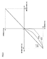
図3は、図2に示す制御対象プロセス200における操作量と加熱能力および冷却能力との特性例を示す図である。本明細書において、「加熱能力」および「冷却能力」を割合で示す場合には、以下のように定義される。
FIG. 3 is a diagram illustrating a characteristic example of the operation amount, the heating capacity, and the cooling capacity in the
加熱能力[%]=任意操作量での加熱温度[℃/sec]/最大加熱温度[℃/sec]×100[%]
冷却能力[%]=任意操作量での冷却温度[℃/sec]/最大冷却温度[℃/sec]×100[%]
まず、加熱特性(加熱の操作量に対する加熱能力の関係)については、図3に示すように、ほぼリニアである。つまり線形性を有しているといえる。これは、加熱装置210として電熱ヒータ214が用いられており、操作量に比例する電流(電力)を供給することで、発熱量をリニアに制御できるからである。Heating capacity [%] = heating temperature with arbitrary manipulated variable [° C./sec]/maximum heating temperature [° C./sec]×100 [%]
Cooling capacity [%] = Cooling temperature [° C./sec] at arbitrary manipulated variable / Maximum cooling temperature [° C./sec]×100 [%]
First, as shown in FIG. 3, the heating characteristics (the relationship between the heating capacity and the heating operation amount) are substantially linear. In other words, it can be said to have linearity. This is because an
これに対して、冷却特性(冷却の操作量に対する冷却能力の関係)は、冷却装置220を構成する冷却配管222を流れる冷却媒体に応じて、異なる特性を有する。例えば、冷却媒体として油を用いた場合には、相変化がなく安定しているので、冷却の操作量に対する冷却能力はほぼリニアになる。つまり線形性を有しているといえる。これに対して、冷却媒体として水を用いた場合や、空気を用いた場合(空冷方式)には、冷却の操作量に対する冷却能力は非線形となる。このように、冷却特性は、冷却媒体や冷却方式によって大きく異なったものとなる。
On the other hand, the cooling characteristics (relationship of the cooling capacity with respect to the cooling operation amount) have different characteristics depending on the cooling medium flowing through the
特に、水を用いた水冷方式では、液相から気相に変化する際の気化熱が相対的に大きく、このような気化熱が生じるような領域では冷却能力が非常に大きくなる。そのため、水を用いた冷却方式(水冷方式)では、この気化熱が大きく影響し、非線形性が強くなる。このような水冷方式について、その能力の特性を事前に把握することは容易ではない。 In particular, in the water cooling system using water, the heat of vaporization when changing from the liquid phase to the gas phase is relatively large, and the cooling capacity is very large in a region where such heat of vaporization occurs. For this reason, in the cooling method using water (water cooling method), this heat of vaporization has a great influence and the nonlinearity becomes strong. About such a water cooling system, it is not easy to grasp the characteristics of the capability in advance.
図4は、図2に示す制御対象プロセスにおける操作量と加熱能力および冷却能力との別の特性例を示す図である。図4に示す特性例は、図3に示す水冷方式を採用した場合に、その冷却能力を発揮するための水量を異ならせた場合の冷却能力の特性をそれぞれ示す。図4に示すように、水量を異ならせることで、非線形性を生じる操作量も変化することがわかる。 FIG. 4 is a diagram illustrating another characteristic example of the operation amount, the heating capacity, and the cooling capacity in the process to be controlled illustrated in FIG. The characteristic example shown in FIG. 4 shows the characteristic of the cooling capacity when the water cooling method shown in FIG. 3 is adopted and the amount of water for exhibiting the cooling capacity is varied. As shown in FIG. 4, it can be seen that the operation amount causing the non-linearity also changes by changing the amount of water.
このような非線形性の強いフィードバック制御系に対して、一般的なオートチューニングを実行してPIDパラメータを決定すると、制御性能が悪化し得る。このような制御性能が悪化する理由について以下説明する。 If a general auto-tuning is performed on such a highly nonlinear feedback control system to determine the PID parameter, the control performance may be deteriorated. The reason why such control performance deteriorates will be described below.
図5は、一般的なオートチューニング実行時における制御対象の温度(観測量)および操作量の時間変化の一例を示す図である。図6は、図5に示すオートチューニングの実行によって決定されたPIDパラメータを用いてフィードバック制御を行った場合の制御対象の温度(観測量)および操作量の時間変化の一例を示す図である。より具体的には、図6(a)には、冷却側の操作量と冷却能力との関係を示し、図6(b)には、フィードバック制御時の制御対象の温度(観測量)および操作量の時間変化の一例を示す。 FIG. 5 is a diagram illustrating an example of a temporal change in the temperature (observed amount) and the manipulated variable of the control target during execution of general auto tuning. FIG. 6 is a diagram illustrating an example of a temporal change in the temperature (observed amount) and the manipulated variable of the control target when feedback control is performed using the PID parameter determined by performing the auto-tuning illustrated in FIG. More specifically, FIG. 6A shows the relationship between the operation amount on the cooling side and the cooling capacity, and FIG. 6B shows the temperature (observed amount) to be controlled and the operation during feedback control. An example of the time change of quantity is shown.
図5には、リミットサイクル法を用いたオートチューニング機能の例を示す。図5に示すように、通常のリミットサイクル法を適用した場合には、加熱側の操作量および冷却側の操作量をいずれも最大値(つまり、100%および−100%)として、交互にこれらの操作量を制御対象へ与える。このようにして発生した応答特性に基づいて、制御対象に応じたPIDパラメータが決定される。 FIG. 5 shows an example of an auto-tuning function using the limit cycle method. As shown in FIG. 5, when the normal limit cycle method is applied, the operation amount on the heating side and the operation amount on the cooling side are both set to the maximum values (that is, 100% and −100%), and these are alternately performed. Is given to the control target. Based on the response characteristics generated in this way, the PID parameter corresponding to the control target is determined.
このように決定されたPIDパラメータを用いてフィードバック制御を行うにあたって、実際に使用される操作量がオートチューニング実行時と離れている場合には、非線形性の影響を受けて制御性能が悪化する。すなわち、オートチューニング実行時に、図5に示すように、冷却能力が最大となる操作量が出力されているので、冷却装置220の冷却能力の最大値を前提として冷却能力の特性が推定される。すなわち、オートチューニング機能によって、図6(a)の破線に示すような特性が推定される。その推定された特性に応じたPIDパラメータが決定される。
When performing the feedback control using the PID parameter determined in this way, if the operation amount actually used is different from that at the time of executing the auto tuning, the control performance is deteriorated due to the influence of nonlinearity. That is, when performing auto-tuning, as shown in FIG. 5, the operation amount that maximizes the cooling capacity is output, so the characteristics of the cooling capacity are estimated on the premise of the maximum value of the cooling capacity of the
しかしながら、実際の特性は、推定された特性とは乖離している領域もあり、図6(b)に示すように、操作量が相対的に小さい領域でフィードバック制御を行う場合には、推定された特性に対して、実際の特性は大きく乖離することになる。そのため、相対的に小さい操作量を用いて制御対象230を制御すると、オートチューニング機能によって設定されたPIDパラメータが前提とする想定より現実の冷却能力が高くなり、制御対象230を冷し過ぎるという事態が生じる。
However, there are areas where the actual characteristics deviate from the estimated characteristics. As shown in FIG. 6B, the actual characteristics are estimated when feedback control is performed in a region where the operation amount is relatively small. The actual characteristics will be greatly different from the actual characteristics. Therefore, when the
具体的には、冷却側の操作量を相対的に小さい領域(例えば、10〜30%)で制御対象230を冷却すると、図6(b)に示すように、何らかの外乱に応答して冷却が開始されると、目標値に対して温度が下がり過ぎてしまうとともに、振動的な温度変動が生じてしまい、その収束に時間を要する。このように、オートチューニング機能によって推定された冷却能力と実際の冷却能力との乖離によって、制御性能が悪化する。
Specifically, when the controlled
[D.解決手段の概要]
上述のような強い非線形性を有する制御対象230を含むフィードバック制御系に対して、より適切なPIDパラメータを設定できるオートチューニング機能について説明する。[D. Summary of solution]
An auto-tuning function that can set a more appropriate PID parameter for the feedback control system including the
本実施の形態においては、オートチューニングにおいて使用する操作量を段階的に変更しつつ、最も好ましい操作量の大きさを探索する。そして、最も好ましい操作量における応答特性に基づいてPIDパラメータを決定する。 In the present embodiment, the most preferable magnitude of the operation amount is searched while changing the operation amount used in the auto-tuning step by step. Then, the PID parameter is determined based on the response characteristic at the most preferable operation amount.
より具体的には、調節器100は、そのオートチューニング機能として、第1の操作量(冷却側の操作量)および第2の操作量(加熱側の操作量)の交互出力において、出力の切替毎に第1の操作量(冷却側の操作量)の大きさを順次変更するとともに、第1の操作量(冷却側の操作量)に対する制御量の第1の変化が線形性を有していると判断されたときに取得された応答特性からPIDパラメータを決定する。すなわち、調節器100は、冷却側の操作量を段階的に変更しつつ、リミットサイクルを複数回実行する。そして、各リミットサイクルの結果が予め定められた条件を満たすと判断されると、調節器100は、そのときの冷却特性(応答特性)から、冷却側のPIDパラメータを算出する。なお、加熱特性(応答特性)から、加熱側のPIDパラメータも算出される。
More specifically, the
図7は、本実施の形態に係る調節器100によるオートチューニング実行時の時間波形例を示す図である。図8は、本実施の形態に係る調節器100によるオートチューニング実行時の操作量の冷却能力の特性上における変化を示す図である。
FIG. 7 is a diagram illustrating an example of a time waveform when auto-tuning is performed by the
本実施の形態においては、冷却能力に非線形性が存在するので、調節器100は、図7に示すように、オートチューニングの各サイクルにおいて、冷却側の操作量の大きさを順次変更していく。なお、加熱能力に非線形性が存在する制御系であれば、加熱側の操作量の大きさについても順次変更していけばよい。
In the present embodiment, since there is nonlinearity in the cooling capacity, the
より具体的には、1回目のリミットサイクルにおける冷却側の操作量MVc_1を100%と設定し、2回目のリミットサイクルにおける冷却側の操作量MVc_2を1回目の操作量MVc_1をρ_1倍した値に設定し、3回目のリミットサイクルにおける冷却側の操作量MVc_3を2回目の操作量MVc_2をρ_2倍した値に設定する。以下同様にして、冷却側の操作量MVcをリミットサイクル毎に変更する。このように冷却側の操作量MVcを順次変更することで、オートチューニングにおいて考慮される冷却能力の大きさは、図8に示すように順次変化する。 More specifically, the operation amount MVc_1 on the cooling side in the first limit cycle is set to 100%, and the operation amount MVc_2 on the cooling side in the second limit cycle is set to a value obtained by multiplying the first operation amount MVc_1 by ρ_1. The cooling operation amount MVc_3 in the third limit cycle is set to a value obtained by multiplying the second operation amount MVc_2 by ρ_2. Similarly, the operation amount MVc on the cooling side is changed for each limit cycle. Thus, by sequentially changing the operation amount MVc on the cooling side, the size of the cooling capacity considered in the auto tuning changes sequentially as shown in FIG.
ここで、冷却側の操作量MVcの変更係数ρ_i(0<ρ_i<1)については、予め定められた一定値を採用してもよいが、直前の交互出力によって取得された応答特性から、新たな交互出力における冷却側の操作量MVcの大きさを決定することが好ましい。このような直前の交互出力の応答特性を利用する一例として、本実施の形態においては、加熱と冷却とのシステムゲイン比(能力比)を表す以下の比を用いる。 Here, as the change coefficient ρ_i (0 <ρ_i <1) of the operation amount MVc on the cooling side, a predetermined constant value may be adopted, but a new value is obtained from the response characteristic acquired by the immediately previous alternate output. It is preferable to determine the magnitude of the operation amount MVc on the cooling side in such alternate output. As an example of using the response characteristic of the alternating output just before, in this embodiment, the following ratio representing the system gain ratio (capacity ratio) between heating and cooling is used.
変更係数ρ_i=冷却出力時間Toff_i−1/加熱出力時間Ton_i−1
但し、冷却出力時間Toff_i−1は、(i−1)回目(前回)のリミットサイクルにおいて冷却側の操作量MVcが0に維持される時間の長さを示し、加熱出力時間Ton_i−1は、(i−1)回目(前回)のリミットサイクルにおいて冷却側の操作量MVcが出力される時間の長さを示す(図7参照)。Change coefficient ρ_i = cooling output time Toff_i−1 / heating output time Ton_i−1
However, the cooling output time Toff_i-1 indicates the length of time during which the cooling-side manipulated variable MVc is maintained at 0 in the (i-1) th (previous) limit cycle, and the heating output time Ton_i-1 is (I-1) Indicates the length of time during which the cooling-side manipulated variable MVc is output in the first (previous) limit cycle (see FIG. 7).
このとき、冷却出力時間Toff_i−1と加熱出力時間Ton_i−1との大きさの関係によっては、上述の式において、変更係数ρ_iが1を超える場合もあるので、算出される変更係数ρ_iが変更係数上限値ρ_max以下になるように制限することが好ましい。 At this time, depending on the relationship between the cooling output time Toff_i−1 and the heating output time Ton_i−1, the change coefficient ρ_i may exceed 1 in the above formula, so the calculated change coefficient ρ_i is changed. It is preferable to limit so as to be equal to or less than the coefficient upper limit value ρ_max.
このように、調節器100は、そのオートチューニング機能として、直前の交互出力において第1の操作量(冷却側の操作量)が出力された期間(冷却出力時間Toff)の長さと第2の操作量(加熱側の操作量)が出力された期間(加熱出力時間Ton)の長さとに応じて、当該直前の交互出力における第1の操作量の大きさを補正することで、新たな交互出力における第1の操作量の大きさを決定する。
As described above, the
次に、上述のような、冷却側の操作量MVcを順次変更した探索を終了する条件としては、冷却特性(冷却の操作量に対する冷却能力の関係)上において、線形性を有している領域の操作量であると判断されたことを採用してもよい。ここで、調節器100は、そのオートチューニング機能として、順次変更される第1の操作量(冷却側の操作量)の大きさ別に、第1の操作量に対応する制御量の変化速度との関係を評価することで、第1の操作量に対する制御量の第1の変化が線形性を有しているか否かを判断する。
Next, as a condition for ending the search in which the operation amount MVc on the cooling side is sequentially changed as described above, a region having linearity on the cooling characteristics (relationship of the cooling capacity with respect to the operation amount of cooling). It may be adopted that the operation amount is determined as follows. Here, as an auto-tuning function of the
より具体的には、この冷却特性上における線形性については、以下に説明するような誤差を用いて評価できる。すなわち、リミットサイクルの終了条件は、算出される誤差が予め設定したしきい値以下になったことを含む。 More specifically, the linearity on the cooling characteristic can be evaluated using an error as described below. That is, the end condition of the limit cycle includes that the calculated error is equal to or less than a preset threshold value.
そして、最終のリミットサイクルにおいて観測された冷却特性および加熱特性(応答特性)に基づいて、ZiegleおよびNicholsの限界感度法などを用いて、PIDパラメータが算出される。なお、PIDパラメータの算出方法については、公知の任意の方法を採用できる。 Then, based on the cooling characteristics and heating characteristics (response characteristics) observed in the final limit cycle, the PID parameters are calculated using the limit sensitivity method of Ziegle and Nichols. In addition, about the calculation method of a PID parameter, a well-known arbitrary method is employable.
但し、制御系の特性によっては、算出される誤差が予め設定したしきい値以下にならない場合も想定されるため、発生したリミットサイクルの数が上限値(N回)に到達すれば、リミットサイクルを終了させてもよい。すなわち、調節器100は、そのオートチューニング機能として、第1の操作量(冷却側の操作量)に対する制御量の第1の変化が線形性を有していると判断されなくとも、第1の操作量および第2の操作量の交互出力が予め定められた回数実行されると、最終の交互出力において取得された応答特性からPIDパラメータを決定する。
However, depending on the characteristics of the control system, it may be assumed that the calculated error does not fall below the preset threshold value. Therefore, if the number of generated limit cycles reaches the upper limit (N times), the limit cycle May be terminated. In other words, the
このようなオートチューニング方法を採用することで、制御対象が線形性を有している場合であっても、非線形性を有している場合であっても、適切なPIDパラメータを算出できる。例えば、図1に示す制御系においては、冷却媒体の種類(水や油)などに応じて、オートチューニングの手順などを変更する必要がない。 By adopting such an auto-tuning method, an appropriate PID parameter can be calculated regardless of whether the controlled object has linearity or non-linearity. For example, in the control system shown in FIG. 1, it is not necessary to change the auto-tuning procedure or the like according to the type of coolant (water or oil).
[E.誤差評価]
次に、線形性を有している領域の操作量であるか否かを判断するための誤差について説明する。図9は、本実施の形態に係る調節器100によるオートチューニングにおける誤差の評価方法を説明するための図である。図9に示すように、本実施の形態における「誤差」は、冷却特性(冷却の操作量に対する冷却能力の関係)において、前回のリミットサイクルで用いた操作量に対応する冷却能力で定義される直線に対して、今回のリミットサイクルで用いた操作量に対応する冷却能力がどの程度離れているかという度合いを示す値に相当する。[E. Error evaluation]
Next, an error for determining whether or not the operation amount is in a region having linearity will be described. FIG. 9 is a diagram for explaining an error evaluation method in auto-tuning by the
具体的には、図9に示すように、原点をP0とし、リミットサイクルi回目の冷却能力点をPi(Pi.x,Pi.y)と定義する。ここで、Pi.xは、冷却側操作量を示し、Pi.yは、冷却能力を示す。また、冷却能力Pi.yは、リミットサイクル1回目における温度低下時の傾き(変化速度)R1に対する、リミットサイクルi回目における温度低下時の傾きRiの比から算出される(つまり、Pi.y=Ri/R1)。そして、リミットサイクルi回目の各々において、冷却能力Piと原点P0とを結ぶ直線Liが設定される。誤差hiは、直線L(i−1)とi回目の冷却能力Pi(Pi.x,Pi.y)との距離として算出される。すなわち、この距離は、リミットサイクルi回目における線形判定の指標である誤差hiとして算出される。図9には、2回目のリミットサイクルについての誤差h2の算出例を示す。 Specifically, as shown in FIG. 9, the origin is defined as P0, and the cooling capacity point for the i-th limit cycle is defined as Pi (Pi.x, Pi.y). Here, Pi. x represents the cooling side manipulated variable, Pi. y represents the cooling capacity. In addition, the cooling capacity Pi. y is calculated from the ratio of the slope Ri at the time of temperature reduction in the limit cycle i to the slope (change rate) R1 at the time of temperature reduction in the first limit cycle (that is, Pi.y = Ri / R1). In each limit cycle i, a straight line Li connecting the cooling capacity Pi and the origin P0 is set. The error hi is calculated as the distance between the straight line L (i-1) and the i-th cooling capacity Pi (Pi.x, Pi.y). That is, this distance is calculated as an error hi that is an index for linear determination at the i th limit cycle. FIG. 9 shows a calculation example of the error h2 for the second limit cycle.
[F.処理手順]
次に、本実施の形態に係る調節器100において実行されるオートチューニングの処理手順について説明する。図10は、実施の形態に係る調節器100において実行されるオートチューニングの処理手順を示すフローチャートである。図10に示す各ステップは、典型的には、調節器100のCPU112がFlashROM114に格納されたプログラムモジュール118に含まれる命令コードを実行することで実現される。図10に示す処理手順は、ユーザなどがオートチューニングの開始を指示すると、予め定められた演算周期(例えば、100msec毎)に繰返し実行される。[F. Processing procedure]
Next, an auto-tuning processing procedure executed in the
図10を参照して、CPU112は、加熱側の操作量として100%を出力し(ステップS100)、制御対象プロセス200から測定された温度(制御対象の温度)PVが設定された目標値(設定温度)SPに到達したか否かを判断する(ステップS102)。制御対象の温度PVが設定温度SPに到達していなければ(ステップS102においてNOの場合)、ステップS100以下の処理が繰返される。
Referring to FIG. 10,
制御対象の温度PVが設定温度SPに到達していれば(ステップS102においてYESの場合)、ステップS104以下の処理が実行される。このステップS100およびS102の処理は、オートチューニングに係るリミットサイクルを発生させるための前処理である。 If temperature PV of control object has reached preset temperature SP (in the case of YES in Step S102), processing after Step S104 will be performed. The processing in steps S100 and S102 is preprocessing for generating a limit cycle related to auto tuning.
CPU112は、カウンタiに「1」をセットし(ステップS104)、1回目のリミットサイクルの発生を指示する(ステップS106)。このカウンタiは、リミットサイクル回数を示す。1回目のリミットサイクルにおける冷却側および加熱側の操作量はいずれも100%とする。リミットサイクルの発生指示は、制御対象の温度PVが設定温度SPと一致するまで冷却側の操作量(この場合は、100%)を出力し、制御対象の温度PVが設定温度SPと一致すると、加熱側の操作量(この場合は、100%)を出力するという一連の処理を含む。
The
1回分のリミットサイクルの発生が完了すると、CPU112は、カウンタiを1だけインクリメントする(ステップS108)。そして、CPU112は、前回のリミットサイクルにおける冷却側の操作量についての冷却出力時間Toff_i−1および加熱出力時間Ton_i−1を用いて、変更係数ρ_i(=Toff_i−1/Ton_i−1)を算出するとともに、算出した変更係数ρ_iを用いて今回の冷却側の操作量MVc_i(=MVc_i−1×ρ_i)を算出する(ステップS110)。
When the generation of one limit cycle is completed, the
続いて、CPU112は、i回目のリミットサイクルの発生を指示する(ステップS112)。i回目のリミットサイクルにおける冷却側の操作量はMVc_i%とし、加熱側の操作量は100%とする。リミットサイクルの発生指示は、制御対象の温度PVが設定温度SPと一致するまで冷却側の操作量(この場合は、MVc_i%)を出力し、制御対象の温度PVが設定温度SPと一致すると、加熱側の操作量(この場合は、100%)を出力するという一連の処理を含む。そして、CPU112は、今回の冷却特性(応答特性)と前回の冷却特性(応答特性)とから誤差hiを算出する(ステップS114)。
Subsequently, the
その後、CPU112は、算出した誤差hiがしきい値γ以下であるか否かを判断する(ステップS116)。算出した誤差hiがしきい値γを超えていれば(ステップS116においてNOの場合)には、CPU112は、現在のカウンタiの値がリミットサイクルの最大値Nに到達しているか否かを判断する(ステップS118)。
Thereafter, the
現在のカウンタiの値がリミットサイクルの最大値Nに到達していなければ(ステップS118においてNOの場合)には、CPU112は、ステップS108以下の処理を実行する。
If the current value of counter i has not reached the maximum value N of the limit cycle (NO in step S118),
これに対して、算出した誤差hiがしきい値γ以下の場合(ステップS116においてYESの場合)、または、現在のカウンタiの値がリミットサイクルの最大値Nに到達している場合(ステップS118においてYESの場合)には、CPU112は、i回目のリミットサイクルにおける応答特性から、PIDパラメータを算出する(ステップS120)。そして、処理は終了する。
On the other hand, when the calculated error hi is equal to or less than the threshold value γ (YES in step S116), or when the current counter i value has reached the maximum value N of the limit cycle (step S118). In the case of YES in step S120, the
[G.制御構成]
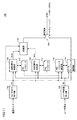
次に、本実施の形態に係る調節器100に搭載されるオートチューニング機能を実現する制御構成について説明する。図11は、本実施の形態に係る調節器100に搭載されるオートチューニング機能を実現する制御構成を示す模式図である。[G. Control configuration]
Next, a control configuration that realizes an auto-tuning function that is mounted on the
図11を参照して、調節器100は、その制御構成として、センサ出力受付部162と、ユーザ設定受付部164と、加熱側PID演算部166と、冷却側PID演算部168と、切換部170と、PIDパラメータ算出部172と、オートチューニング制御部174と、スイッチ180とを含む。
Referring to FIG. 11,
センサ出力受付部162は、温度センサ240からの出力信号を受け付け、所定のレンジ調整などを行った上で、制御対象の温度PVを出力する。ユーザ設定受付部164は、ユーザ操作に従って設定温度SPの設定を受け付ける。なお、外部装置(例えば、PLC(Programmable Logic Control)など)から設定温度SPが設定されることもある。
The sensor
加熱側PID演算部166および冷却側PID演算部168は、通常のPID制御を実行するための部位であり、それぞれPIDパラメータ176および178に従って、制御対象の温度PVと設定温度SPとから、操作量MVhおよびMVcをそれぞれ算出および出力する。PIDパラメータ176および178は、ユーザが直接的に入力してもよいが、本実施の形態においては、後述するPIDパラメータ算出部172によって自動的に設定される。
The heating-side
切換部170は、加熱側PID演算部166および冷却側PID演算部168からそれぞれ出力される操作量MVhおよびMVcを状況に応じて切り替えて出力する。図1に示すフィードバック制御系1では、加熱側PID演算部166および冷却側PID演算部168の両方がアクティブになる必要はないので、操作量を直接的に切り替える方式に代えて、加熱側PID演算部166および冷却側PID演算部168の一方のみを選択的にアクティブ化するような構成を採用してもよい。
The
PIDパラメータ算出部172およびオートチューニング制御部174は、オートチューニングを実行するための部位である。オートチューニング制御部174は、上述したようなリミットサイクルを発生させるための操作量(操作量MVhおよびMVc)を発生する。PIDパラメータ算出部172は、最終のリミットサイクルにおいて観測された加熱特性および冷却特性(応答特性)に基づいて、PIDパラメータ176および178を決定する。
The PID
スイッチ180は、通常の制御時とオートチューニング実行時との間で、操作量の出力元を切り換える。すなわち、通常の制御時には、切換部170からの操作量が制御対象プロセス200へ出力され、オートチューニング実行時には、オートチューニング制御部174からの操作量が制御対象プロセス200へ出力される。
The
[H.オートチューニング結果例]
次に、本実施の形態に係るオートチューニング機能の効果をシミュレーションによって評価した結果について説明する。[H. Example of auto tuning results]
Next, the result of evaluating the effect of the auto tuning function according to the present embodiment by simulation will be described.
図12は、本実施の形態に係るオートチューニングに係る各部の時間波形を示す一例である。図12に示すシミュレーション結果において、冷却側の操作量MVcの変更係数ρ_iは、変更係数ρ_i=冷却出力時間Toff_i−1/加熱出力時間Ton_i−1に従って、各サイクルにおいて算出した。但し、図1に示すフィードバック制御系1に含まれる制御対象プロセス200(すなわち、水冷方式または空冷方式の押出成形機)では、非線形点(特性が急激に変化する部分)は、一般的に、操作量が5〜20%の領域にあるため、変更係数上限値ρ_maxを0.4に設定した。
FIG. 12 is an example showing a time waveform of each part related to auto-tuning according to the present embodiment. In the simulation result shown in FIG. 12, the change coefficient ρ_i of the cooling-side manipulated variable MVc was calculated in each cycle according to the change coefficient ρ_i = cooling output time Toff_i−1 / heating output time Ton_i−1. However, in the
図12に示すシミュレーション結果では、5回目のリミットサイクルにおいて、その誤差hiがしきい値γ以下となった。そのため、5回目のリミットサイクルにおいて観測された冷却特性および加熱特性(応答特性)に基づいて、PIDパラメータが決定される。 In the simulation result shown in FIG. 12, the error hi is equal to or less than the threshold value γ in the fifth limit cycle. Therefore, the PID parameter is determined based on the cooling characteristic and the heating characteristic (response characteristic) observed in the fifth limit cycle.
図12に示すように、加熱側の操作量MVhは100%に維持されているのに対して、冷却側の操作量MVcが順次小さくなっているのがわかる。制御対象の温度PVに生じるリミットサイクルに基づいて、限界感度法などを用いてPIDパラメータが決定される。 As shown in FIG. 12, it can be seen that the operation amount MVh on the heating side is maintained at 100%, whereas the operation amount MVc on the cooling side is gradually decreased. A PID parameter is determined using a limit sensitivity method or the like based on a limit cycle occurring at the temperature PV to be controlled.
図13は、図12に示すオートチューニングの実行によって算出されたPIDパラメータを用いた制御性能の比較例を示す図である。図12には、従来のオートチューニングを用いて決定したPIDパラメータを用いてフィードバック制御を行った結果と、本実施の形態に係るオートチューニングを用いて決定したPIDパラメータを用いてフィードバック制御を行った結果とを示す。 FIG. 13 is a diagram illustrating a comparative example of control performance using the PID parameter calculated by executing the auto-tuning illustrated in FIG. FIG. 12 shows the result of feedback control using PID parameters determined using conventional auto-tuning and the feedback control using PID parameters determined using auto-tuning according to the present embodiment. Results are shown.
図13からわかるように、本実施の形態に係るオートチューニングによって決定したPIDパラメータを用いることで、制御対象の温度PVを設定温度SPとより高精度に一致させることができると言える。 As can be seen from FIG. 13, it can be said that the temperature PV to be controlled can be matched with the set temperature SP with higher accuracy by using the PID parameter determined by the auto-tuning according to the present embodiment.
なお、リミットサイクルの最大値Nを「3」に設定したような場合には、図12に示す段階的に変更される冷却側の操作量MVcのうち、3回目の変更がなされた時点でオートチューニングは完了することになる。この場合であっても、3回目のリミットサイクルにおける冷却側の操作量MVc_3と5回目のリミットサイクルにおける冷却側の操作量MVc_5とは、比較的近い値を示すので、概ね適切なPIDパラメータを決定できる。すなわち、オートチューニングに要する時間とPIDパラメータの精度との関係は、一種のトレードオフの関係にあるが、通常のPID制御において使用される範囲の操作量を用いてオートチューニングを実行すれば、非線形性の影響を回避したPIDパラメータを決定できる。 When the maximum value N of the limit cycle is set to “3”, the auto change is made when the third change is made among the cooling-side manipulated variables MVc shown in FIG. Tuning is complete. Even in this case, the operation amount MVc_3 on the cooling side in the third limit cycle and the operation amount MVc_5 on the cooling side in the fifth limit cycle are relatively close to each other. Therefore, an appropriate PID parameter is determined. it can. That is, the relationship between the time required for auto-tuning and the accuracy of the PID parameter is a kind of trade-off, but if auto-tuning is executed using an operation amount in a range used in normal PID control, nonlinearity is obtained. PID parameters that avoid the influence of sex can be determined.
[I.ユーザインターフェイス]
オートチューニングでは、制御対象に対して実際に何らかの操作量を与えて、その応答特性に基づいてPIDパラメータを算出する。特に、リミットサイクル法では、観測量(PV)を振動させて制御系の特性値を推定するため、時定数の長い制御系では、必要な応答特性を観測するために比較的長い時間を要する。そのため、オートチューニングの実行中において、その実行状態や完了時期(予測値)などをユーザへ通知することが、よりユーザフレンドリである。[I. User interface]
In auto-tuning, a certain amount of operation is actually given to the controlled object, and PID parameters are calculated based on the response characteristics. In particular, in the limit cycle method, since the characteristic value of the control system is estimated by vibrating the observation amount (PV), a control system having a long time constant requires a relatively long time to observe the required response characteristic. Therefore, it is more user-friendly to notify the user of the execution state and completion time (predicted value) during execution of auto-tuning.
以下、このようなオートチューニングに係るユーザ支援のためのユーザインターフェイスの一例について説明する。 Hereinafter, an example of a user interface for user support relating to such auto-tuning will be described.
(i1:オートチューニングの実行状態の通知)
まず、オートチューニングの実行状態を通知するユーザインターフェイスについて説明する。図14は、本実施の形態に係る調節器100が提供するユーザインターフェイスの一例を示す模式図である。図14に示す調節器100は、表示部150を有している。表示部150には、制御対象の温度PVおよび設定温度SPの現在値が表示されている。また、表示部150に近接して配置されたたボタンやスイッチなどをユーザが操作することで、設定温度SPなどが変更される。(I1: Notification of auto tuning execution status)
First, a user interface for notifying the execution state of auto tuning will be described. FIG. 14 is a schematic diagram illustrating an example of a user interface provided by the
図14には、オートチューニングの実行中のある状態を示す。図14に示すように、オートチューニングの実行状態の値として、現在発生しているリミットサイクルの回数、つまり何回目のリミットサイクルが実行されているかが表示される。表示部150は、現在のリミットサイクルの回数を示すインジケータ152を含む。つまり、調節器100は、現在実行されている交互出力の回数を表示する表示手段としての表示部150を含む。
FIG. 14 shows a state during execution of auto tuning. As shown in FIG. 14, the number of limit cycles currently occurring, that is, how many limit cycles are being executed, is displayed as the value of the execution state of auto-tuning.
リミットサイクルの最大値Nが予め設定されているので、ユーザは、このような現在のリミットサイクルの回数を見ることで、オートチューニングがあとどれくらいで完了するのかを知ることができる。 Since the maximum value N of the limit cycle is set in advance, the user can know how much auto-tuning will be completed by looking at the current number of limit cycles.
(i2:オートチューニングの完了時期の通知)
図14に示す現在のリミットサイクルの回数に代えて、あるいは、それ加えて、オートチューニングの完了までに要する時間を通知するようにしてもよい。すなわち、調節器100は、PIDパラメータの決定に必要な交互出力が完了する時期を表示する表示手段としての表示部150を含むようにしてもよい。(I2: Notification of auto-tuning completion time)
Instead of or in addition to the current number of limit cycles shown in FIG. 14, the time required to complete auto-tuning may be notified. That is, the
図15は、本実施の形態に係る調節器100が提供するユーザインターフェイスの別の一例を示す模式図である。
FIG. 15 is a schematic diagram illustrating another example of the user interface provided by the
図15(a)には、オートチューニングの完了までに要する残時間を示すインジケータ154を含む表示部150の例を示す。オートチューニングの完了までに要する残時間を予測する方法としては、まず、1回分のリミットサイクルを発生させて、それに要した時間を計測するとともに、その計測した時間にリミットサイクルの最大値Nを乗じた時間を、残時間として算出することができる。あるいは、リミットサイクルの半サイクル(冷却側または加熱側)の発生に要する時間から残時間を算出してもよい。さらに、以前にオートチューニングを実行したことがある場合には、そのときに取得された応答特性に基づいて、残時間を算出してもよい。
FIG. 15A shows an example of the
また、オートチューニングの完了までに要する残時間ではなく、オートチューニングが完了する時刻を表示するようにしてもよい。図15(b)に示す表示部150は、オートチューニングが完了することが予測される時刻を示すインジケータ156を含む。
Further, the time at which auto-tuning is completed may be displayed instead of the remaining time required to complete auto-tuning. The
このように、比較的時間のかかるオートチューニングについて、完了するタイミングを事前に知ることができるので、ユーザは、時間を有効に活用することができる。 As described above, since it is possible to know in advance the completion timing of the auto-tuning that takes a relatively long time, the user can effectively use the time.
[J.変形例1]
上述の実施の形態においては、加熱と冷却とのシステムゲイン比(能力比)を表す変更係数ρ_iを乗じることで、冷却側の操作量MVcを順次変更する構成例について説明した。この変更係数ρ_iについては、これに限らず任意の値に設定できる。また、各リミットサイクルにおいて変更係数ρ_iを動的に決定する構成に代えて、一連のオートチューニングにおいて変更係数ρとして固定値を採用してもよい。[J. Modification 1]
In the above-described embodiment, the configuration example in which the operation amount MVc on the cooling side is sequentially changed by multiplying the change coefficient ρ_i representing the system gain ratio (capacity ratio) between heating and cooling has been described. The change coefficient ρ_i is not limited to this and can be set to an arbitrary value. Further, instead of the configuration in which the change coefficient ρ_i is dynamically determined in each limit cycle, a fixed value may be adopted as the change coefficient ρ in a series of auto-tuning.
このように変更係数ρ_i(あるいは、変更係数ρ(固定値))については、制御対象などに応じて適宜設定すればよい。一方で、オートチューニングに要する時間を可能な限り短縮したいというニーズもある。そこで、変更係数に係る一つの変形例として、上述した加熱と冷却とのシステムゲイン比(能力比)という技術的意義を失わず、かつ、より短時間でオートチューニングが完了するための構成について説明する。 Thus, the change coefficient ρ_i (or the change coefficient ρ (fixed value)) may be set as appropriate according to the control target. On the other hand, there is a need to reduce the time required for auto tuning as much as possible. Therefore, as a modification of the change coefficient, a configuration for completing the auto-tuning in a shorter time without losing the technical significance of the system gain ratio (capacity ratio) between heating and cooling described above will be described. To do.
本変形例においては、各リミットサイクルが終了すると、次のリミットサイクルに用いられる新たな操作量として、現在の操作量に変更係数ρ_iの二乗を乗じた値を用いる。すなわち、以下のような数式に従って、操作量MVc_iを順次変更する。 In this modification, when each limit cycle ends, a value obtained by multiplying the current operation amount by the square of the change coefficient ρ_i is used as a new operation amount used in the next limit cycle. That is, the manipulated variable MVc_i is sequentially changed according to the following mathematical formula.
変更係数ρ_i=冷却出力時間Toff_i−1/加熱出力時間Ton_i−1
操作量MVc_i=MVc_1−1×ρ_i×ρ_i
このように、変更係数ρ_iの二乗を用いることで、図12に示すような冷却側の操作量MVcを段階的に変更する処理において、実質的に一つ飛ばしで操作量MVcを変更することになる。すなわち、調節器100は、そのオートチューニング機能として、直前の交互出力における第2の操作量(加熱側の出力)が出力された期間(加熱出力時間Ton)の長さに対する第1の操作量(加熱側の出力)が出力された期間(冷却出力時間Toff)の長さの比(ρ)の二乗に応じて、当該直前の交互出力における第1の操作量の大きさを補正することで、新たな交互出力における第1の操作量の大きさを決定する。Change coefficient ρ_i = cooling output time Toff_i−1 / heating output time Ton_i−1
Manipulation amount MVc_i = MVc — 1−1 × ρ_i × ρ_i
Thus, by using the square of the change coefficient ρ_i, in the process of changing the operation amount MVc on the cooling side in a stepwise manner as shown in FIG. 12, the operation amount MVc is changed substantially by skipping one. Become. That is, as an auto-tuning function of the
図16は、本実施の形態の変形例1に係るオートチューニングに係る各部の時間波形を示す一例である。変更係数ρ_iを乗じて操作量MVcを順次変更する場合(図12)には、5回のリミットサイクルを発生させなければ、誤差hiがしきい値γ以下にならなかったが、図16に示すように、変更係数ρ_iの二乗を乗じて操作量MVcを順次変更することで、リミットサイクルを3回の発生させることで、誤差hiをしきい値γ以下にできる。このように、制御対象が非線形性を有していることが予めわかっている場合には、操作量MVcを変更させる度合いをより大きくすることで、オートチューニングに係る時間を短縮化できる。 FIG. 16 is an example showing a time waveform of each part related to auto-tuning according to the first modification of the present embodiment. When the manipulated variable MVc is sequentially changed by multiplying by the change coefficient ρ_i (FIG. 12), the error hi does not become the threshold value γ or less unless five limit cycles are generated. Thus, by multiplying the square of the change coefficient ρ_i and sequentially changing the manipulated variable MVc, the error hi can be made equal to or less than the threshold value γ by generating the limit cycle three times. As described above, when it is known in advance that the control target has nonlinearity, the time for auto-tuning can be shortened by increasing the degree of changing the operation amount MVc.
[K.変形例2]
上述の変形例1においては、加熱と冷却とのシステムゲイン比(能力比)を表す変更係数ρ_iの二乗を乗じることで、操作量MVcを順次変更する例について説明した。しかしながら、変更係数ρ_iの二乗に限られることなく、変更係数ρ_iのn乗(n>1)を乗じて、操作量MVcを順次変更してもよい。以下、このような変更係数ρ_iのn乗(n>1)を乗じて、操作量MVcを順次変更してもよい理由について説明する。[K. Modification 2]
In the first modification described above, the example in which the manipulated variable MVc is sequentially changed by multiplying the square of the change coefficient ρ_i representing the system gain ratio (capacity ratio) between heating and cooling has been described. However, the manipulated variable MVc may be sequentially changed by multiplying the change coefficient ρ_i by the nth power (n> 1) without being limited to the square of the change coefficient ρ_i. Hereinafter, the reason why the manipulated variable MVc may be sequentially changed by multiplying the nth power (n> 1) of such a change coefficient ρ_i will be described.
上述したような押出成形機232において、冷却能力は、加熱能力より大きく、かつ、非線形性を有している。また、リミットサイクル法を用いたオートチューニング機能では、発生させるリミットサイクルを正弦波に近付けるほど、その精度を高めることができる。
In the
図17は、図2に示す制御対象プロセスにおける加熱能力および冷却能力と操作量(加熱および冷却)との間の関係の一例を示す図である。図17に示す特性例において、第1象限は、加熱能力(縦軸)と操作量(加熱)(横軸)との関係を示す。Ahは、操作量(加熱)が100%のときの加熱能力[℃/sec]の大きさを示す。また、第3象限は、冷却能力(縦軸)と操作量(冷却)(横軸)との関係を示す。Acは、操作量(冷却)が100%のときの冷却能力[℃/sec]の大きさを示す。なお、冷却能力は、設備の設置条件や設定条件によって変化するため、図17には、設定条件を3つに異ならせた場合の冷却能力の特性をそれぞれ示す。 FIG. 17 is a diagram illustrating an example of a relationship between the heating capacity and the cooling capacity and the operation amount (heating and cooling) in the process to be controlled illustrated in FIG. In the characteristic example shown in FIG. 17, the first quadrant shows the relationship between the heating capacity (vertical axis) and the operation amount (heating) (horizontal axis). Ah indicates the magnitude of the heating capacity [° C./sec] when the operation amount (heating) is 100%. The third quadrant shows the relationship between the cooling capacity (vertical axis) and the operation amount (cooling) (horizontal axis). Ac indicates the size of the cooling capacity [° C./sec] when the operation amount (cooling) is 100%. Since the cooling capacity varies depending on the installation conditions and setting conditions of the equipment, FIG. 17 shows the characteristics of the cooling capacity when the setting conditions are changed to three.
ここで、図17において、冷却能力の特性が変化する点(図17において●印で示す点)を非線形点と定義する。 Here, in FIG. 17, a point at which the characteristic of the cooling capacity changes (a point indicated by a mark ● in FIG. 17) is defined as a non-linear point.
上述の実施の形態において説明した加熱と冷却とのシステムゲイン比(能力比)を表す変更係数ρ_2(=冷却出力時間Toff_1/加熱出力時間Ton_1)を用いて、2回目のリミットサイクルにおける冷却側の操作量MVc_2を算出する場合には、以下のような数式に従って算出される。 Using the change coefficient ρ_2 (= cooling output time Toff_1 / heating output time Ton_1) representing the system gain ratio (capacity ratio) between heating and cooling described in the above embodiment, the cooling side in the second limit cycle is changed. When calculating the operation amount MVc_2, it is calculated according to the following mathematical formula.
MVc_2=100%×変更係数ρ_2
図17において、この数式に従って算出される2回目のリミットサイクルにおける冷却側の操作量MVc_2を○印で示す。すなわち、上の数式は、冷却能力の特性を線形とした場合に、加熱の能力と冷却の能力とのバランスを揃えるための計算式に相当する。MVc_2 = 100% × change coefficient ρ_2
In FIG. 17, the operation amount MVc_2 on the cooling side in the second limit cycle calculated according to this mathematical formula is indicated by a circle. In other words, the above formula corresponds to a calculation formula for balancing the heating capability and the cooling capability when the characteristics of the cooling capability are linear.
ここで、図17に示すように、例えば、冷却特性1について算出すべき冷却特性(線形特性)の範囲は、操作量が○印で示す点より小さい領域である。そのため、加熱と冷却との比(能力比)を乗じるだけでは、2回目のリミットサイクルにおける冷却側の操作量MVc_2が、非線形点(●印で示す位置)より大きいため、図17の矢印で示す範囲(線形部分)の特性を捉えることができないことになる。また、図17に示す他の冷却特性についても、それぞれの非線形点(●印で示す位置)が変化するため、加熱と冷却とのシステムゲイン比(能力比)を乗じるだけでは、線形部分を捉えることができない。 Here, as shown in FIG. 17, for example, the range of the cooling characteristic (linear characteristic) to be calculated for the cooling characteristic 1 is an area where the operation amount is smaller than the point indicated by a circle. Therefore, simply by multiplying the ratio of heating and cooling (capacity ratio), the operation amount MVc_2 on the cooling side in the second limit cycle is larger than the non-linear point (position indicated by the mark ●), and is indicated by the arrow in FIG. The characteristics of the range (linear part) cannot be captured. Also, with respect to the other cooling characteristics shown in FIG. 17, since the respective nonlinear points (positions indicated by ●) change, the linear portion is captured only by multiplying the system gain ratio (capacity ratio) between heating and cooling. I can't.
そこで、図17に示すような冷却特性を有する制御対象に対しては、上述のような数式に対して、非線形点より小さい範囲の線形特性を捉えるために、補正係数Xc(0<Xc<1)を導入する。すなわち、加熱と冷却とのシステムゲイン比(能力比)を表す変更係数ρ_2(=冷却出力時間Toff_1/加熱出力時間Ton_1)を用いて、2回目のリミットサイクルにおける冷却側の操作量MVc_2を算出する場合には、以下のような数式に従って算出される。 Therefore, for a control object having a cooling characteristic as shown in FIG. 17, a correction coefficient Xc (0 <Xc <1) is used to capture a linear characteristic in a range smaller than the non-linear point with respect to the above formula. ). That is, using the change coefficient ρ_2 (= cooling output time Toff_1 / heating output time Ton_1) representing the system gain ratio (capacity ratio) between heating and cooling, the operation amount MVc_2 on the cooling side in the second limit cycle is calculated. In this case, it is calculated according to the following mathematical formula.
MVc_2=100%×変更係数ρ_2×補正係数Xc
このような数式を用いることで、図17において、○印で示す位置(変更係数ρ_1を乗じることで算出される2回目のリミットサイクルにおける冷却側の操作量)は、さらにXc倍され、非線形点(●印で示す位置)より小さい点(つまり、ゼロ側)へ補正されることになる(破線の丸印)。MVc_2 = 100% × change coefficient ρ_2 × correction coefficient Xc
By using such a mathematical expression, the position indicated by a circle in FIG. 17 (the operation amount on the cooling side in the second limit cycle calculated by multiplying by the change coefficient ρ_1) is further multiplied by Xc, and the nonlinear point It is corrected to a point (that is, the zero side) smaller than (the position indicated by the mark ●) (dotted circle).
図17の冷却能力1〜3に示すように、非線形点(●印で示す位置)は、冷却能力(図17に示すAc)が大きくなるほどY軸に近づく傾向がある。すなわち、非線形点(●印で示す位置)のX座標値は、冷却能力の逆数(1/Ac)と因果関係があるといえる。
As shown in the
ここで、冷却能力の逆数(1/Ac)∝加熱と冷却とのシステムゲイン比(能力比:Ah/Ac)∝能力比(変更係数ρ)の関係が成立すると考えられるので、非線形点(●印で示す位置)の横軸の座標値は、能力比(変更係数ρ)と因果関係があるといえる。 Here, since it is considered that the relationship between the reciprocal of the cooling capacity (1 / Ac) ∝heating and cooling and the system gain ratio (capacity ratio: Ah / Ac) ∝capacity ratio (change coefficient ρ) holds, the nonlinear point (● It can be said that the coordinate value on the horizontal axis of the position indicated by the mark has a causal relationship with the capability ratio (change coefficient ρ).
図17に示すような特性は、加熱装置210および冷却装置220を含む押出成形機232において得られる。但し、加熱装置210により制御対象に生じる加熱についての制御量は、対応する操作量について相対的に強い線形性を有しており、冷却装置220により制御対象に生じる冷却についての制御量は、対応する操作量について相対的に強い非線形性を有している。そして、このような押出成形機232を制御対象とした場合には、補正係数Xcと能力比(変更係数ρ)との間の因果関係をXc=ρm(0.5≦m≦2.0)とモデル化することで、算出される2回目のリミットサイクルにおける冷却側の操作量(破線の丸印)が非線形点(●印で示す位置)より縦軸により近くなり、線形部分の特性を捉えることができる。この関係は、冷却能力の大きさが変化しても、押出成形機232においては成立すると考えられる。The characteristics as shown in FIG. 17 are obtained in the
したがって、補正係数Xcを含む上式は、以下のように変形できる。
MVc_2=100%×変更係数ρ_2×変更係数ρ_2m
=100%×変更係数ρ_2(m+1)=100%×変更係数ρ_2n
このように、現在の操作量に変更係数ρ_iのn乗を乗じた値を用いることで、操作量MVc_iが順次変更される。このn乗のnとしては、2の近傍の値を用いることが好ましい。より具体的には、調節器100は、1.5≦n≦3.0を満たすようなnを用いて、新たな交互出力における第1の操作量(冷却側の操作量)の大きさを決定する。Therefore, the above equation including the correction coefficient Xc can be modified as follows.
MVc_2 = 100% × change coefficient ρ_2 × change coefficient ρ_2 m
= 100% × change coefficient ρ_2 (m + 1) = 100% × change coefficient ρ_2 n
As described above, the operation amount MVc_i is sequentially changed by using a value obtained by multiplying the current operation amount by the nth power of the change coefficient ρ_i. It is preferable to use a value in the vicinity of 2 as n to the power of n. More specifically, the
このように、制御対象が非線形性を有していることが予めわかっている場合には、操作量MVcの変更係数のn乗を乗じて、新たなリミットサイクルにおける操作量MVcを算出することで、オートチューニングに係る時間を短縮化できる。 Thus, when it is known in advance that the controlled object has nonlinearity, the manipulated variable MVc in a new limit cycle is calculated by multiplying the manipulated variable MVc by the nth power of the change coefficient. The time for auto tuning can be shortened.
[L.変形例3]
上述の実施の形態においては、リミットサイクルを複数回発生させる例について説明したが、ある種類の制御対象については、1回のリミットサイクルによって取得される応答特性のみから適切なパラメータを決定することもできる。以下、1回のリミットサイクルを発生、つまり第1の操作量(冷却側の操作量)および第2の操作量(加熱側の操作量)を観測量に応じて交互に出力し、それによって取得される応答特性のみからパラメータを決定する方法について説明する。[L. Modification 3]
In the above-described embodiment, the example in which the limit cycle is generated a plurality of times has been described. However, for a certain type of control target, an appropriate parameter may be determined only from the response characteristic acquired by one limit cycle. it can. Thereafter, one limit cycle is generated, that is, the first manipulated variable (cooling-side manipulated variable) and the second manipulated variable (heating-side manipulated variable) are alternately output according to the observed quantity, and acquired by that. A method for determining the parameter only from the response characteristics to be performed will be described.
図18は、本実施の形態の変形例3に係るパラメータを決定する過程を説明するための図である。図18を参照して、まず、冷却側の操作量MVcを100%としてリミットサイクル(1回目)を発生させる。このとき、加熱側の操作量MVhも同じく100%とする。リミットサイクルの発生によって取得された応答特性(時間波形)から冷却能力Yc[℃/sec]を算出する。冷却側の操作量MVcを変化させたとしても、冷却能力Ycが変化しないと仮定して、もし2回目のリミットサイクルを発生させたのであれば、得られるであろう特性を推定する。 FIG. 18 is a diagram for explaining a process of determining parameters according to the third modification of the present embodiment. Referring to FIG. 18, first, a limit cycle (first time) is generated with the operation amount MVc on the cooling side being 100%. At this time, the operation amount MVh on the heating side is also set to 100%. The cooling capacity Yc [° C./sec] is calculated from the response characteristic (time waveform) acquired by the occurrence of the limit cycle. Even if the cooling-side manipulated variable MVc is changed, assuming that the cooling capacity Yc does not change, if the second limit cycle is generated, the characteristics that will be obtained are estimated.
より具体的には、非線形点(図18において●印で示す点)に相当する冷却側の操作量Xcを上述の変形例2に係る方法によって算出する。すなわち、1回目のリミットサイクルにおいて生じた応答特性に基づいて、加熱出力時間Tonに対する冷却出力時間Toffの比から変更係数ρを決定し、この決定された変更係数ρをn乗(但し、1.5≦n≦3.0)して得られる値を非線形点に相当する冷却側の操作量Xcとして決定する。さらに、静的または動的に決定される補正係数を乗じた値を採用してもよい。非線形点において、1回目のリミットサイクルから決定された冷却能力と同一の冷却能力Yc[℃/sec]が維持されていると仮定して、上述のような手順によって決定された操作量Xc[%]を用いて、非線形点の特性値を推定する。すなわち、図18に示す座標系における非線形点の座標は[Xc,Yc]となる。この非線形点[Xc,Yc]と原点[0,0]とを結ぶ直線(推定線)についての傾きAc[℃/sec]を線形性が維持される操作量Xcの範囲における冷却能力として決定する。そして、この冷却能力Ac[℃/sec]を用いて、PIDパラメータが決定される。 More specifically, the operation amount Xc on the cooling side corresponding to the non-linear point (the point indicated by ● in FIG. 18) is calculated by the method according to the above-described second modification. That is, based on the response characteristics generated in the first limit cycle, the change coefficient ρ is determined from the ratio of the cooling output time Toff to the heating output time Ton, and the determined change coefficient ρ is n-th power (where 1. 5 ≦ n ≦ 3.0) is determined as the cooling-side manipulated variable Xc corresponding to the nonlinear point. Furthermore, a value obtained by multiplying a correction coefficient determined statically or dynamically may be adopted. Assuming that the same cooling capacity Yc [° C./sec] as the cooling capacity determined from the first limit cycle is maintained at the nonlinear point, the manipulated variable Xc [%] determined by the procedure as described above. ] Is used to estimate the characteristic value of the nonlinear point. That is, the coordinates of the nonlinear point in the coordinate system shown in FIG. 18 are [Xc, Yc]. The slope Ac [° C./sec] for the straight line (estimated line) connecting the nonlinear point [Xc, Yc] and the origin [0, 0] is determined as the cooling capacity in the range of the manipulated variable Xc in which the linearity is maintained. . Then, using this cooling capacity Ac [° C./sec], the PID parameter is determined.
このように、本変形例においては、(1)1回目のリミットサイクル応答特性(時間波形)から冷却能力Yc[℃/sec]を算出し、(2)非線形点の冷却操作量Xc[%]を推定し、(3)冷却能力は冷却側の操作量が100%の場合と同等に維持されると仮定して非線形点[Xc,Yc]を決定し、(4)非線形点[Xc,Yc]と、原点とを通る推定線の傾きAcを冷却能力として算出し、(5)冷却能力Acを用いてPIDパラメータを算出する。 Thus, in this modification, (1) the cooling capacity Yc [° C./sec] is calculated from the first limit cycle response characteristic (time waveform), and (2) the cooling operation amount Xc [%] at the non-linear point. (3) The non-linear point [Xc, Yc] is determined on the assumption that the cooling capacity is maintained at the same level as when the operation amount on the cooling side is 100%, and (4) the non-linear point [Xc, Yc] ] And the slope Ac of the estimated line passing through the origin is calculated as the cooling capacity, and (5) the PID parameter is calculated using the cooling capacity Ac.
本変形例においては、調節器100は、オートチューニング機能として、第1の操作量(冷却側の操作量)および第2の操作量(加熱側の操作量)を観測量に応じて交互に1回ずつ出力し、第1の操作量(冷却側の操作量)および第2の操作量(加熱側の操作量)の1回ずつの交互出力によって取得された応答特性(時間波形)からPIDパラメータを決定する。このオートチューニング機能において、調節器100は、応答特性から第1の操作量(冷却側の操作量)に対する制御量の第1の変化が線形性を維持できる第1の操作量(冷却側の操作量)の範囲(すなわち、非線形点)を推定するとともに、当該推定した範囲からPIDパラメータを決定する。
In this modification, the
本変形例に係るオートチューニング機能の有効性を確認するために、上述した本実施の形態に係るオートチューニング機能と比較した結果を示す。より具体的には、本実施の形態に係るオートチューニング機能(非線形点の特性を実際に計測)と本変形例に係るオートチューニング機能(非線形点の特性を推定)とにおいてそれぞれ算出したPIDパラメータ(一例として、比例ゲイン(比例帯))間の乖離度合い(誤差率)を比較した。 In order to confirm the effectiveness of the auto-tuning function according to this modification, a result of comparison with the above-described auto-tuning function according to the present embodiment is shown. More specifically, the PID parameters calculated by the auto-tuning function (actually measuring the characteristics of the nonlinear point) according to the present embodiment and the auto-tuning function (estimating the characteristics of the nonlinear point) according to this modification ( As an example, the degree of deviation (error rate) between proportional gains (proportional bands)) was compared.
図19は、本変形例に係るオートチューニング機能によって算出されたPIDパラメータの誤差率の評価結果例を示す図である。図19に示す評価結果例においては、推定された非線形点(冷却側の操作量)毎に算出された誤差率eをプロットしている。この誤差率eは、本実施の形態に係るオートチューニング機能を用いて算出された比例帯Pb0と、本変形例に係るオートチューニング機能を用いて算出された比例帯Pbとを用いて、以下に示す式に従って算出される。 FIG. 19 is a diagram illustrating an example of an evaluation result of the error rate of the PID parameter calculated by the auto-tuning function according to the present modification. In the evaluation result example shown in FIG. 19, the error rate e calculated for each estimated nonlinear point (cooling side operation amount) is plotted. This error rate e is as follows using the proportional band Pb0 calculated using the auto-tuning function according to the present embodiment and the proportional band Pb calculated using the auto-tuning function according to the present modification. It is calculated according to the formula shown.
誤差e=(Pb−Pb0)/Pb0×100[%]
図19には、図2に示す冷却装置220に示すような、鋳込みヒータ冷却方式に適用した場合の評価結果を示す。図19に示す評価結果によれば、上述の本実施の形態に係るオートチューニング機能(非線形点の特性を実際に計測)に比較して、その誤差率は、平均が約10%で、最大値でも25%以内に収まっている。そのため、十分に実用的な精度が得られることがわかる。Error e = (Pb−Pb0) / Pb0 × 100 [%]
FIG. 19 shows an evaluation result when applied to a cast-in heater cooling system as shown in the
以上のとおり、本変形例においては、2回目のリミットサイクルは発生させることなく、1回目のリミットサイクルによって取得された応答特性(時間波形)から非線形点を推定し、そしてPIDパラメータを決定する。リミットサイクルを1回だけ発生させて、その結果からPIDパラメータを決定するという方法を採用することで、リミットサイクルを複数回発生させる場合に比較して、やや推定精度は低下する可能性はあるが、実用上の問題はない程度の精度低下であり、それにもまして、オートチューニングに要する時間を短縮することができるので、チューニング作業の時間効率を高めることができる。 As described above, in this modified example, the second limit cycle is not generated, the nonlinear point is estimated from the response characteristic (time waveform) acquired by the first limit cycle, and the PID parameter is determined. By adopting a method of generating a limit cycle only once and determining the PID parameter from the result, there is a possibility that the estimation accuracy may be slightly reduced as compared with the case of generating a limit cycle multiple times. The accuracy is lowered to such a degree that there is no problem in practical use. Furthermore, since the time required for auto-tuning can be shortened, the time efficiency of the tuning operation can be improved.
今回開示された実施の形態はすべての点で例示であって制限的なものではないと考えられるべきである。本発明の範囲は、上記した説明ではなく、請求の範囲によって示され、請求の範囲と均等の意味および範囲内でのすべての変更が含まれることが意図される。 The embodiment disclosed this time should be considered as illustrative in all points and not restrictive. The scope of the present invention is defined by the terms of the claims, rather than the description above, and is intended to include any modifications within the scope and meaning equivalent to the terms of the claims.
1 フィードバック制御系、100 調節器、110 制御部、112 CPU、114 ROM、116 RAM、118 プログラムモジュール、120 入力部、130 出力部、132 加熱側出力部、134 冷却側出力部、140 設定部、150 表示部、152,154,156 インジケータ、162 センサ出力受付部、164 ユーザ設定受付部、166 加熱側PID演算部、168 冷却側PID演算部、170 切換部、172 PIDパラメータ算出部、174 オートチューニング制御部、176 PIDパラメータ、180 スイッチ、200 制御対象プロセス、210 加熱装置、212 ソリッドステートリレー、214 電熱ヒータ、220 冷却装置、222 冷却配管、224 電磁弁、226 水温調整設備、230 制御対象、232 押出成形機、234 スクリュー、236 バレル、240 温度センサ。 1 feedback control system, 100 regulator, 110 control unit, 112 CPU, 114 ROM, 116 RAM, 118 program module, 120 input unit, 130 output unit, 132 heating side output unit, 134 cooling side output unit, 140 setting unit, 150 display unit, 152, 154, 156 indicator, 162 sensor output reception unit, 164 user setting reception unit, 166 heating side PID calculation unit, 168 cooling side PID calculation unit, 170 switching unit, 172 PID parameter calculation unit, 174 auto tuning Control unit, 176 PID parameter, 180 switch, 200 process to be controlled, 210 heating device, 212 solid state relay, 214 electric heater, 220 cooling device, 222 cooling pipe, 224 solenoid valve, 226 water temperature adjustment equipment, 30 control subjects, 232 extruder, 234 screw, 236 barrels, 240 temperature sensor.
Claims (13)
制御対象から取得される観測量が目標値と一致するように、予め設定されたパラメータに従って、前記制御対象の制御量に第1の変化を生じさせるための第1の操作量、または、前記制御量に前記第1の変化とは反対の第2の変化を生じさせるための第2の操作量、を選択的に決定する操作量決定手段と、
前記第1の操作量および前記第2の操作量を前記観測量に応じて交互に出力し、当該交互出力によって取得された応答特性から前記パラメータを決定するチューニング手段とを備え、
前記チューニング手段は、前記第1の操作量および前記第2の操作量の交互出力において、出力の切替毎に前記第1の操作量の大きさを順次変更するとともに、前記第1の操作量に対する前記制御量の第1の変化が線形性を有していると判断されたときに取得された応答特性から前記パラメータを決定する、調節器。 A controller having an auto-tuning function,
The first manipulated variable or the control for causing a first change in the control amount of the control target according to a preset parameter so that the observation amount acquired from the control target matches the target value An operation amount determining means for selectively determining a second operation amount for causing a second change in the amount opposite to the first change;
Tuning means for alternately outputting the first manipulated variable and the second manipulated variable according to the observed quantity, and determining the parameter from response characteristics acquired by the alternate output;
In the alternate output of the first manipulated variable and the second manipulated variable, the tuning means sequentially changes the magnitude of the first manipulated variable every time the output is switched, and with respect to the first manipulated variable. A regulator that determines the parameter from a response characteristic acquired when it is determined that the first change in the control amount has linearity.
制御対象から取得される観測量が目標値と一致するように、予め設定されたパラメータに従って、前記制御対象の制御量に第1の変化を生じさせるための第1の操作量、または、前記制御量に前記第1の変化とは反対の第2の変化を生じさせるための第2の操作量、を選択的に決定するステップと、
前記第1の操作量および前記第2の操作量を前記観測量に応じて交互に出力し、当該交互出力によって取得された応答特性から前記パラメータを決定するステップとを備え、
前記パラメータを決定するステップは、前記第1の操作量および前記第2の操作量の交互出力において、出力の切替毎に前記第1の操作量の大きさを順次変更するとともに、前記第1の操作量に対する前記制御量の第1の変化が線形性を有していると判断されたときに取得された応答特性から前記パラメータを決定するステップを含む、制御方法。 A control method in a regulator having an auto-tuning function,
The first manipulated variable or the control for causing a first change in the control amount of the control target according to a preset parameter so that the observation amount acquired from the control target matches the target value Selectively determining a second manipulated variable for causing a second change in amount opposite to the first change;
Alternately outputting the first manipulated variable and the second manipulated variable according to the observed quantity, and determining the parameter from response characteristics acquired by the alternate output,
In the step of determining the parameter, in the alternate output of the first manipulated variable and the second manipulated variable, the magnitude of the first manipulated variable is sequentially changed every time the output is switched, and the first manipulated variable is changed. A control method including the step of determining the parameter from a response characteristic acquired when it is determined that the first change of the control amount with respect to the manipulated variable has linearity.
制御対象から取得される観測量が目標値と一致するように、予め設定されたパラメータに従って、前記制御対象の制御量に第1の変化を生じさせるための第1の操作量、または、前記制御量に前記第1の変化とは反対の第2の変化を生じさせるための第2の操作量、を選択的に決定するステップと、
前記第1の操作量および前記第2の操作量を前記観測量に応じて交互に出力し、当該交互出力によって取得された応答特性から前記パラメータを決定するステップとを実行させ、
前記パラメータを決定するステップは、前記第1の操作量および前記第2の操作量の交互出力において、出力の切替毎に前記第1の操作量の大きさを順次変更するとともに、前記第1の操作量に対する前記制御量の第1の変化が線形性を有していると判断されたときに取得された応答特性から前記パラメータを決定するステップを含む、制御プログラム。 A control program for realizing a regulator having an auto-tuning function, wherein the control amount of the control target is set according to a parameter set in advance so that an observation amount acquired from the control target matches a target value. A first operation amount for causing a change of 1 or a second operation amount for causing a second change in the control amount opposite to the first change is selectively determined. Steps,
Alternately outputting the first manipulated variable and the second manipulated variable according to the observed quantity, and determining the parameter from the response characteristics acquired by the alternate output,
In the step of determining the parameter, in the alternate output of the first manipulated variable and the second manipulated variable, the magnitude of the first manipulated variable is sequentially changed every time the output is switched, and the first manipulated variable is changed. A control program comprising a step of determining the parameter from a response characteristic acquired when it is determined that the first change of the control amount with respect to an operation amount has linearity.
Applications Claiming Priority (3)
| Application Number | Priority Date | Filing Date | Title |
|---|---|---|---|
| JP2012268201 | 2012-12-07 | ||
| JP2012268201 | 2012-12-07 | ||
| PCT/JP2013/080404 WO2014087805A1 (en) | 2012-12-07 | 2013-11-11 | Adjustment device, control method, and control program |
Related Child Applications (1)
| Application Number | Title | Priority Date | Filing Date |
|---|---|---|---|
| JP2016105557A Division JP6197914B2 (en) | 2012-12-07 | 2016-05-26 | Controller, control method and control program |
Publications (2)
| Publication Number | Publication Date |
|---|---|
| JP5983765B2 true JP5983765B2 (en) | 2016-09-06 |
| JPWO2014087805A1 JPWO2014087805A1 (en) | 2017-01-05 |
Family
ID=50883231
Family Applications (2)
| Application Number | Title | Priority Date | Filing Date |
|---|---|---|---|
| JP2014551009A Active JP5983765B2 (en) | 2012-12-07 | 2013-11-11 | Controller, control method and control program |
| JP2016105557A Active JP6197914B2 (en) | 2012-12-07 | 2016-05-26 | Controller, control method and control program |
Family Applications After (1)
| Application Number | Title | Priority Date | Filing Date |
|---|---|---|---|
| JP2016105557A Active JP6197914B2 (en) | 2012-12-07 | 2016-05-26 | Controller, control method and control program |
Country Status (7)
| Country | Link |
|---|---|
| US (1) | US10248084B2 (en) |
| EP (1) | EP2930573B1 (en) |
| JP (2) | JP5983765B2 (en) |
| KR (2) | KR101738282B1 (en) |
| CN (1) | CN104813244B (en) |
| TW (1) | TWI587106B (en) |
| WO (1) | WO2014087805A1 (en) |
Families Citing this family (12)
| Publication number | Priority date | Publication date | Assignee | Title |
|---|---|---|---|---|
| JP2015124835A (en) * | 2013-12-26 | 2015-07-06 | 東ソー株式会社 | Solenoid valve drive circuit |
| US10496057B2 (en) * | 2015-01-19 | 2019-12-03 | Lennox Industries Inc. | HVAC system, a method for operating the HVAC system and a HVAC controller configured for the same |
| JP6383309B2 (en) * | 2015-03-17 | 2018-08-29 | アズビル株式会社 | Control device and control method |
| TWI564683B (en) | 2015-10-21 | 2017-01-01 | 財團法人工業技術研究院 | Parameter tuning method of unknown pid controller |
| JP6718124B2 (en) * | 2015-11-02 | 2020-07-08 | 理化工業株式会社 | PID control device and PID control method |
| WO2017077309A1 (en) * | 2015-11-06 | 2017-05-11 | Bae Systems Plc | Aircraft environmental control system |
| JP6751244B2 (en) * | 2016-11-30 | 2020-09-02 | 理化工業株式会社 | Auto tuning device |
| JP7164348B2 (en) | 2018-07-27 | 2022-11-01 | アズビル株式会社 | Controller |
| JP7304722B2 (en) * | 2018-11-29 | 2023-07-07 | 東京エレクトロン株式会社 | Temperature control device, temperature control method, and inspection device |
| US11169204B2 (en) * | 2018-11-29 | 2021-11-09 | Tokyo Electron Limited | Temperature control device, temperature control method, and inspection apparatus |
| JP2020160659A (en) * | 2019-03-26 | 2020-10-01 | アズビル株式会社 | Control device and control method |
| JP7361624B2 (en) * | 2020-02-12 | 2023-10-16 | 東京エレクトロン株式会社 | Heating source life estimation system, life estimation method, and inspection device |
Citations (4)
| Publication number | Priority date | Publication date | Assignee | Title |
|---|---|---|---|---|
| JPH0527802A (en) * | 1991-07-17 | 1993-02-05 | Rika Kogyo Kk | Controller |
| JPH06161509A (en) * | 1992-11-24 | 1994-06-07 | Mitsubishi Electric Corp | Autotuning controller |
| JPH06161569A (en) * | 1992-11-19 | 1994-06-07 | Komatsu Ltd | Temperature control method for cooling/heating enable element |
| JP2009157691A (en) * | 2007-12-27 | 2009-07-16 | Omron Corp | Auto-tuning method, temperature controller, and heat treatment device |
Family Cites Families (14)
| Publication number | Priority date | Publication date | Assignee | Title |
|---|---|---|---|---|
| US4912381A (en) * | 1985-05-31 | 1990-03-27 | Kollmorgen Corporation | Adaptive control system |
| CN1026444C (en) * | 1987-04-03 | 1994-11-02 | 株式会社日立制作所 | PID control system |
| US5245528A (en) * | 1989-03-20 | 1993-09-14 | Hitachi, Ltd. | Process control apparatus and method for adjustment of operating parameters of controller of the process control apparatus |
| JP2802460B2 (en) * | 1992-04-11 | 1998-09-24 | 理化工業株式会社 | Heating / cooling controller |
| JP3211444B2 (en) * | 1993-01-11 | 2001-09-25 | オムロン株式会社 | Control device |
| US5572558A (en) * | 1994-11-17 | 1996-11-05 | Cirrus Logic, Inc. | PID loop filter for timing recovery in a sampled amplitude read channel |
| US6980869B1 (en) * | 2000-11-20 | 2005-12-27 | National Instruments Corporation | System and method for user controllable PID autotuning and associated graphical user interface |
| JP3881593B2 (en) * | 2002-05-17 | 2007-02-14 | 株式会社山武 | Control device |
| US6870468B2 (en) * | 2002-09-27 | 2005-03-22 | Nissan Motor Co., Ltd. | Adaptive cruise speed controlling apparatus and method for automotive vehicle |
| JP4291002B2 (en) | 2003-01-20 | 2009-07-08 | 株式会社山武 | Limit cycle auto-tuning method and heat-cool control device |
| US7035694B2 (en) * | 2003-05-13 | 2006-04-25 | National Instruments Corporation | Automatic tuning of motion controllers using search techniques |
| US20060207272A1 (en) * | 2005-03-16 | 2006-09-21 | Yamatake Corporation | Control apparatus using time proportioning control |
| CN102176176B (en) * | 2011-01-17 | 2014-03-12 | 国家电网公司 | Sliding-pressure operation unit optimizing control method in automatic gain control (AGC) mode |
| CN102807390B (en) * | 2012-08-26 | 2013-10-16 | 西安墙体材料研究设计院 | Porous sintering heat-insulating hollow block and manufacturing process thereof |
-
2013
- 2013-11-11 CN CN201380061335.8A patent/CN104813244B/en active Active
- 2013-11-11 KR KR1020157013777A patent/KR101738282B1/en active IP Right Grant
- 2013-11-11 JP JP2014551009A patent/JP5983765B2/en active Active
- 2013-11-11 WO PCT/JP2013/080404 patent/WO2014087805A1/en active Application Filing
- 2013-11-11 US US14/646,993 patent/US10248084B2/en active Active
- 2013-11-11 EP EP13860031.7A patent/EP2930573B1/en active Active
- 2013-11-11 KR KR1020177012724A patent/KR101849509B1/en active IP Right Grant
- 2013-12-05 TW TW102144573A patent/TWI587106B/en active
-
2016
- 2016-05-26 JP JP2016105557A patent/JP6197914B2/en active Active
Patent Citations (4)
| Publication number | Priority date | Publication date | Assignee | Title |
|---|---|---|---|---|
| JPH0527802A (en) * | 1991-07-17 | 1993-02-05 | Rika Kogyo Kk | Controller |
| JPH06161569A (en) * | 1992-11-19 | 1994-06-07 | Komatsu Ltd | Temperature control method for cooling/heating enable element |
| JPH06161509A (en) * | 1992-11-24 | 1994-06-07 | Mitsubishi Electric Corp | Autotuning controller |
| JP2009157691A (en) * | 2007-12-27 | 2009-07-16 | Omron Corp | Auto-tuning method, temperature controller, and heat treatment device |
Also Published As
| Publication number | Publication date |
|---|---|
| KR101849509B1 (en) | 2018-05-28 |
| JP6197914B2 (en) | 2017-09-20 |
| KR20150079818A (en) | 2015-07-08 |
| US10248084B2 (en) | 2019-04-02 |
| TWI587106B (en) | 2017-06-11 |
| TW201435525A (en) | 2014-09-16 |
| EP2930573A1 (en) | 2015-10-14 |
| JP2016170806A (en) | 2016-09-23 |
| KR20170056710A (en) | 2017-05-23 |
| CN104813244B (en) | 2018-01-05 |
| JPWO2014087805A1 (en) | 2017-01-05 |
| US20150309482A1 (en) | 2015-10-29 |
| WO2014087805A1 (en) | 2014-06-12 |
| EP2930573B1 (en) | 2018-02-21 |
| EP2930573A4 (en) | 2016-07-20 |
| KR101738282B1 (en) | 2017-05-19 |
| CN104813244A (en) | 2015-07-29 |
Similar Documents
| Publication | Publication Date | Title |
|---|---|---|
| JP6197914B2 (en) | Controller, control method and control program | |
| JP5075701B2 (en) | Control device and power estimation method | |
| WO2014185141A1 (en) | Simulation method, recording medium wherein simulation program is stored, simulation device, and system | |
| CN111552330B (en) | Screen heating control method and system applied to terminal starting | |
| EP2725434A1 (en) | Feedback control method, feedback control apparatus, and feedback control program | |
| US10340774B2 (en) | Temperature estimating device of electric motor | |
| JP6859725B2 (en) | PID controller, PID control method, and PID control program | |
| WO2016042589A1 (en) | Control apparatus | |
| JP6070145B2 (en) | Controller, operation amount output method, program, and storage medium | |
| JP6874379B2 (en) | Control device, control method, control program | |
| JP2009157691A (en) | Auto-tuning method, temperature controller, and heat treatment device | |
| JP6555429B2 (en) | Temperature measuring device, temperature indicator and temperature controller | |
| JP6874719B2 (en) | Heating device and abnormality detection method for heating device | |
| JP6417175B2 (en) | Evaluation apparatus and evaluation method | |
| JP6800025B2 (en) | Control device and display method | |
| JP2012160144A (en) | Data collection apparatus and data collection method | |
| JP6751244B2 (en) | Auto tuning device | |
| JPWO2006061892A1 (en) | Temperature control method and temperature control device | |
| JP2010231671A (en) | Process monitoring device and process monitoring method | |
| JP2015069612A (en) | Fault detection system and fault detection method |
Legal Events
| Date | Code | Title | Description |
|---|---|---|---|
| TRDD | Decision of grant or rejection written | ||
| A01 | Written decision to grant a patent or to grant a registration (utility model) |
Free format text: JAPANESE INTERMEDIATE CODE: A01 Effective date: 20160705 |
|
| A61 | First payment of annual fees (during grant procedure) |
Free format text: JAPANESE INTERMEDIATE CODE: A61 Effective date: 20160718 |
|
| R150 | Certificate of patent or registration of utility model |
Ref document number: 5983765 Country of ref document: JP Free format text: JAPANESE INTERMEDIATE CODE: R150 |