JP5981103B2 - Linear motor - Google Patents
Linear motor Download PDFInfo
- Publication number
- JP5981103B2 JP5981103B2 JP2011142207A JP2011142207A JP5981103B2 JP 5981103 B2 JP5981103 B2 JP 5981103B2 JP 2011142207 A JP2011142207 A JP 2011142207A JP 2011142207 A JP2011142207 A JP 2011142207A JP 5981103 B2 JP5981103 B2 JP 5981103B2
- Authority
- JP
- Japan
- Prior art keywords
- linear motor
- linear motion
- motion shaft
- linear
- main body
- Prior art date
- Legal status (The legal status is an assumption and is not a legal conclusion. Google has not performed a legal analysis and makes no representation as to the accuracy of the status listed.)
- Expired - Fee Related
Links
Images


Classifications
-
- H—ELECTRICITY
- H02—GENERATION; CONVERSION OR DISTRIBUTION OF ELECTRIC POWER
- H02K—DYNAMO-ELECTRIC MACHINES
- H02K41/00—Propulsion systems in which a rigid body is moved along a path due to dynamo-electric interaction between the body and a magnetic field travelling along the path
- H02K41/02—Linear motors; Sectional motors
- H02K41/03—Synchronous motors; Motors moving step by step; Reluctance motors
- H02K41/031—Synchronous motors; Motors moving step by step; Reluctance motors of the permanent magnet type
-
- H—ELECTRICITY
- H02—GENERATION; CONVERSION OR DISTRIBUTION OF ELECTRIC POWER
- H02K—DYNAMO-ELECTRIC MACHINES
- H02K41/00—Propulsion systems in which a rigid body is moved along a path due to dynamo-electric interaction between the body and a magnetic field travelling along the path
- H02K41/02—Linear motors; Sectional motors
-
- H—ELECTRICITY
- H02—GENERATION; CONVERSION OR DISTRIBUTION OF ELECTRIC POWER
- H02K—DYNAMO-ELECTRIC MACHINES
- H02K35/00—Generators with reciprocating, oscillating or vibrating coil system, magnet, armature or other part of the magnetic circuit
- H02K35/02—Generators with reciprocating, oscillating or vibrating coil system, magnet, armature or other part of the magnetic circuit with moving magnets and stationary coil systems
Description
本発明は、可動子が固定子に対して往復移動するリニアモータに関するものである。 The present invention relates to a linear motor in which a mover reciprocates with respect to a stator.
特許第4385406号公報には、軸線方向に往復移動する直動軸及び直動軸に取付けられた永久磁石列を備えてなる可動子と、可動子が内部空間内を往復移動するように巻線導体がコイル状に巻回されてなる複数の励磁巻線が配置された構造を有する固定子とを備えた複数のリニアモータユニットが示されている。複数のリニアモータユニットは、それぞれ直動軸が平行に並ぶように配置されている。複数のリニアモータユニットのそれぞれの固定子の外側には、複数のリニアモータユニットのそれぞれの磁気回路の一部を構成する磁性材料のパイプからなるバックヨークが設けられている。そして、バックヨークが設けられた複数のリニアモータユニットは、ブロック状のフレームとカバーとに挟まれて支持されている。 Japanese Patent No. 4385406 discloses a mover comprising a linear motion shaft that reciprocates in the axial direction and a permanent magnet array attached to the linear motion shaft, and a winding so that the mover reciprocates in the internal space. A plurality of linear motor units including a stator having a structure in which a plurality of exciting windings formed by winding a conductor in a coil shape are shown. The plurality of linear motor units are arranged so that the linear axes are arranged in parallel. Outside the stator of each of the plurality of linear motor units, a back yoke made of a magnetic material pipe that constitutes a part of the magnetic circuit of each of the plurality of linear motor units is provided. The plurality of linear motor units provided with the back yoke are supported by being sandwiched between a block-shaped frame and a cover.
このような従来のリニアモータでは、パイプからなるバックヨークを複数のリニアモータユニットにそれぞれ取り付けるため、製造が煩雑であった。また、複数のリニアモータユニットを支持するブロック状のフレーム及びカバーを用いる必要があり、リニアモータの体積及び重量が大きくなるという問題があった。 In such a conventional linear motor, the back yoke made of a pipe is attached to each of the plurality of linear motor units, so that the manufacturing is complicated. In addition, it is necessary to use a block-shaped frame and a cover for supporting a plurality of linear motor units, and there is a problem that the volume and weight of the linear motor increase.
本発明の目的は、複数のリニアモータユニットに容易にバックヨークを取り付けることができるリニアモータを提供することにある。 An object of the present invention is to provide a linear motor in which a back yoke can be easily attached to a plurality of linear motor units.
本発明の他の目的は、上記目的に加えて、リニアモータの体積及び重量を小さくできるリニアモータを提供することにある。 Another object of the present invention is to provide a linear motor capable of reducing the volume and weight of the linear motor in addition to the above object.
本発明のリニアモータは、複数のリニアモータユニットとバックヨークとを備えている。複数のリニアモータユニットは、軸線方向に往復移動する直動軸及び直動軸に取付けられた複数の永久磁石からなる1以上の永久磁石列を備えてなる可動子と、可動子が内部空間内を往復移動するように巻線導体がコイル状に巻回されてなる複数の励磁巻線が直動軸の軸線に沿って並ぶように配置された構造を有する固定子とを備えた複数のリニアモータユニットを用いる。複数のリニアモータユニットは、それぞれ直動軸が平行に並ぶように配置されている。バックヨークは、複数のリニアモータユニットのそれぞれの固定子の外側に設けられて、複数のリニアモータユニットのそれぞれの磁気回路の一部を構成する。そして、バックヨークは、磁性材料からなり、複数のリニアモータユニットを全体的に包む包囲部を備えたバックヨーク・アセンブリによって構成されている。 The linear motor of the present invention includes a plurality of linear motor units and a back yoke. The plurality of linear motor units include a linear movement shaft that reciprocates in the axial direction, and a movable element that includes one or more permanent magnet rows each composed of a plurality of permanent magnets attached to the linear movement shaft. And a plurality of linear elements each having a stator having a structure in which a plurality of exciting windings formed by winding a winding conductor in a coil shape so as to reciprocate are arranged along the axis of a linear motion shaft Use a motor unit. The plurality of linear motor units are arranged so that the linear axes are arranged in parallel. The back yoke is provided outside the stator of each of the plurality of linear motor units, and constitutes a part of the magnetic circuit of each of the plurality of linear motor units. The back yoke is made of a magnetic material, and is constituted by a back yoke assembly including an enclosing portion that entirely encloses the plurality of linear motor units.
本発明のように、バックヨークを複数のリニアモータユニットを全体的に包む包囲部を備えたバックヨーク・アセンブリによって構成すれば、複数のリニアモータユニット全体に対して一組のバックヨーク・アセンブリを組み合わせるだけで複数のリニアモータユニットに容易にバックヨークを取り付けることができる。また、本発明のリニアモータでは、バックヨークをそのまま外部の被取付部材等に取り付ければよく、従来のように、複数のリニアモータユニットを支持するブロック状のフレーム及びカバー等の部材を用いる必要がない。そのため、リニアモータの体積及び重量を小さくできる。 As in the present invention, if the back yoke is constituted by a back yoke assembly having an enveloping portion that entirely encloses a plurality of linear motor units, a set of back yoke assemblies can be provided for the entire plurality of linear motor units. A back yoke can be easily attached to a plurality of linear motor units simply by combining them. In the linear motor of the present invention, the back yoke may be attached to an external member to be attached as it is, and it is necessary to use a member such as a block frame and a cover for supporting a plurality of linear motor units as in the prior art. Absent. Therefore, the volume and weight of the linear motor can be reduced.
バックヨーク・アセンブリは、前述の包囲部の内部に固定されて、隣接する2つのリニアモータユニット間を仕切って両者の間に共通磁気回路を形成する仕切り壁部を備えているのが好ましい。このようにすれば、隣接する2つのリニアモータユニットの間に共通磁気回路を容易に形成することができる。 The back yoke assembly is preferably provided with a partition wall portion that is fixed inside the above-described surrounding portion and partitions between two adjacent linear motor units to form a common magnetic circuit therebetween. If it does in this way, a common magnetic circuit can be easily formed between two adjacent linear motor units.
バックヨーク・アセンブリの包囲部は、複数のリニアモータユニットが並ぶ方向に分割面が延びるように組み合わされた分割可能な第1及び第2の分割アセンブリから構成し、仕切り壁部は、第1及び第2の分割アセンブリに嵌め合わせ構造を介して固定することができる。このようにすれば、第1及び第2の分割アセンブリと仕切り壁部とを組み合わせるだけでバックヨーク・アセンブリを容易に組み立てられる。 The surrounding portion of the back yoke assembly is composed of a first and a second divided assemblies that can be divided so that the dividing surfaces extend in a direction in which a plurality of linear motor units are arranged, and the partition wall portion includes the first and second divided assemblies. It can be secured to the second split assembly via a mating structure. In this way, the back yoke assembly can be easily assembled only by combining the first and second divided assemblies and the partition wall portion.
第1及び第2の分割アセンブリは、同じ寸法及び形状を有しているのが好ましい。このようにすれば、1種類の分割アセンブリを第1及び第2の分割アセンブリのいずれの分割アセンブリにも用いることができる。 The first and second split assemblies preferably have the same dimensions and shape. In this way, one type of split assembly can be used for either of the first and second split assemblies.
第1及び第2の分割アセンブリは、磁性板をプレス加工して成形することができる。このようにすれば、第1及び第2の分割アセンブリの形状が複雑な形状であっても、プレス加工により容易に第1及び第2の分割アセンブリを形成できる。また、磁性板を用いるので、リニアモータの体積及び重量を小さくできる。 The first and second divided assemblies can be formed by pressing a magnetic plate. In this way, even if the shapes of the first and second divided assemblies are complicated, the first and second divided assemblies can be easily formed by pressing. Further, since the magnetic plate is used, the volume and weight of the linear motor can be reduced.
通常、複数の励磁巻線には、それぞれ励磁巻線に電力を供給するリード線が接続されている。この場合、第1及び第2の分割アセンブリの少なくとも一方には、リード線が通過する貫通穴を形成するのが好ましい。このようにすれば、リード線を容易に外部に導出できる。 Normally, lead wires for supplying power to the excitation windings are connected to the plurality of excitation windings. In this case, it is preferable to form a through hole through which the lead wire passes in at least one of the first and second divided assemblies. In this way, the lead wire can be easily led out.
貫通穴は軸線方向に延びるスリットから構成することができる。この場合、貫通穴の軸線方向中心と、第1の分割アセンブリまたは第2の分割アセンブリの軸線方向中心との間の寸法は1/4τp〜1/2τp(τp=前記複数の永久磁石のピッチ)の範囲内とし、貫通穴の軸線方向の長さ寸法は(n−1/2)τp〜(n+1/2)τp(n=自然数,τp=前記複数の永久磁石のピッチ)とするのが好ましい。このようにすれば、スリット端部によるコギングの影響を小さくできる。 The through hole can be constituted by a slit extending in the axial direction. In this case, the dimension between the axial center of the through hole and the axial center of the first divided assembly or the second divided assembly is 1 / 4τp to 1 / 2τp (τp = pitch of the plurality of permanent magnets). And the length dimension in the axial direction of the through hole is preferably (n−1 / 2) τp to (n + 1/2) τp (n = natural number, τp = pitch of the plurality of permanent magnets). . In this way, the influence of cogging due to the slit end can be reduced.
固定子は、内部に可動子が配置され且つ励磁巻線が装着される絶縁パイプを備えることができる。その場合、絶縁パイプの軸線方向の両端には、直動軸の両端を軸線方向に移動可能に且つ周方向に回転不可能に支持する軸受が固定された一対のエンドブラケットを固定する。そして、バックヨーク・アセンブリは、一対のエンドブラケットに亘って配置するのが好ましい。このようにすれば、絶縁パイプに励磁巻線が装着するだけで容易に複数の励磁巻線を配置することができる。そして、バックヨーク・アセンブリをしっかりと複数のリニアモータユニットに固定できる。 The stator can include an insulating pipe in which a mover is disposed and an excitation winding is mounted. In that case, a pair of end brackets to which bearings that support both ends of the linear movement shaft in the axial direction and non-rotatably in the circumferential direction are fixed to both ends in the axial direction of the insulating pipe. The back yoke assembly is preferably disposed across the pair of end brackets. In this way, a plurality of excitation windings can be easily arranged simply by mounting the excitation windings on the insulating pipe. The back yoke assembly can be firmly fixed to a plurality of linear motor units.
直動軸は、同じ極性の磁極が向き合うように並べられた複数の永久磁石からなる永久磁石列が収容される筒状の直動軸本体と、直動軸本体の軸線方向の両端に接続されて一対の軸受にそれぞれ支持される一対の直動軸端部材とから構成することができる。その場合、直動軸本体と一対の直動軸端部材とは、連結ピースにより連結し、直動軸本体は、連結ピースの外周部に嵌合して固定し、直動軸端部材は、連結ピースの内周部に嵌合して固定するのが好ましい。このようにすれば、嵌合作業だけで容易に直動軸本体と一対の直動軸端部材とを連結ピースを介して接続できる。 The linear motion shaft is connected to a cylindrical linear motion shaft main body that houses a permanent magnet array composed of a plurality of permanent magnets arranged so that magnetic poles of the same polarity face each other, and both ends of the linear motion shaft main body in the axial direction. And a pair of linear motion shaft end members respectively supported by the pair of bearings. In that case, the linear motion shaft main body and the pair of linear motion shaft end members are connected by a connecting piece, the linear motion shaft main body is fitted and fixed to the outer periphery of the connection piece, and the linear motion shaft end member is It is preferable to fit and fix to the inner peripheral part of a connection piece. In this way, the linear motion shaft main body and the pair of linear motion shaft end members can be easily connected via the connecting piece only by the fitting operation.
連結ピースの外周部は、直動軸本体の長手方向中心側に位置する滑面部と、直動軸本体の長手方向中心から離れた側に位置する粗面部とを有しており、直動軸本体の両端部は連結ピースの滑面部と粗面部の両方に接触して配置するのが好ましい。このようにすれば、直動軸本体と連結ピースとの同芯を保ちつつ直動軸本体と連結ピースとをしっかりと固定できる。 The outer peripheral portion of the connecting piece has a smooth surface portion located on the longitudinal center side of the linear motion shaft main body and a rough surface portion located on the side away from the longitudinal center of the linear motion shaft main body. It is preferable that both ends of the main body are arranged in contact with both the smooth surface portion and the rough surface portion of the connecting piece. If it does in this way, a linear motion axis | shaft main body and a connection piece can be fixed firmly, maintaining the concentricity of a linear motion axis | shaft main body and a connection piece.
また、連結ピースの外周部に複数の凹部を形成し、直動軸本体の両端部に、複数の凹部に嵌合する複数の凸部を形成することができる。このようにすれば、連結ピースの複数の凹部と直動軸本体の複数の凸部との嵌合により、連結ピースと直動軸本体とを強固に固定できる。 Moreover, a some recessed part can be formed in the outer peripheral part of a connection piece, and the several convex part fitted to a some recessed part can be formed in the both ends of a linear_motion | direct_drive shaft main body. If it does in this way, a connection piece and a direct-acting shaft main body can be firmly fixed by fitting with a plurality of crevices of a connecting piece, and a plurality of convex parts of a direct-acting shaft main part.
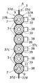
以下、本発明の実施の形態の一例を詳細に説明する。図1及び図2は、本発明のリニアモータの一例の正面図及び右側面図である。本図に示すように、本例のリニアモータ1は、6個のリニアモータユニット3とバックヨーク5とを有している。1個のリニアモータユニット3は、図3に示すように、可動子7と固定子9とを有している。なお、図3は、リニアモータユニット3の断面図であるが、理解を容易にするため、後述する一対の直動軸端部材19A,19B、永久磁石21及び連結ピース25は、平面で表している。可動子7は、直動軸11と、永久磁石列13と、リニアスケール15とを有している。直動軸11は、直動軸本体17と、一対の直動軸端部材19A,19Bとを有しており、軸線方向に往復移動する。図4及び図5に示すように、直動軸本体17は、非磁性のステンレスからなる円筒形のパイプからなり、内部には永久磁石列13が収容されている。なお、図4は図3の部分拡大図であり、図5は図4において後述する連結ピース25及び直動軸端部材19Aを断面で表わした図である。永久磁石列13は、複数の円柱形の永久磁石21が鉄などの磁性材料からなるスペーサ23を介して並べた構造を有している。複数の永久磁石21は、隣り合う2つの永久磁石が軸線方向に同じ極性の磁極が向き合うように並べられている。
Hereinafter, an example of an embodiment of the present invention will be described in detail. 1 and 2 are a front view and a right side view of an example of the linear motor of the present invention. As shown in the figure, the
図3に示すように、一対の直動軸端部材19A,19Bは、細長い円柱形を有している。一対の直動軸端部材19A,19Bは、直動軸本体17の軸線方向の両端に接続されて、後述する一対の軸受35にそれぞれスラスト方向にスライド可能に支持されている。図3に向かって右側に位置する直動軸端部材19Bには、リニアスケール15が取り付けられている。リニアスケール15は、リニアモータの外部に配置された図示しないリニアセンサと対向するように配置されている。リニアスケール15と図示しないリニアセンサとにより、可動子7の位置を検出する位置検出装置が構成される。なお、図2には、リニアスケールの図示は省略してある。一対の直動軸端部材19A,19Bは、図4及び図5に示すように、連結ピース25により直動軸本体17に連結されている。連結ピース25は、鉄、ステンレス等の金属材料からなり、図5に示すように、内部に中空部25aを有している。中空部25aは、小径部25bと、小径部25bより径寸法が大きく小径部25bの両側に位置する大径部25c,25dとを有している。言い換えるならば、中空部25aの軸線方向中央に近い部分に径方向内側に突出する突部25eが形成されている。また、図4に示すように、連結ピース25の外周部25fは、直動軸本体17の長手方向中心側に位置する表面が滑らかな滑面部25gと、直動軸本体17の長手方向中心から離れた側に位置する表面が粗い粗面部25hとを有している。粗面部25hは、加工器具で0.1〜0.3mm程度の棘のような傷をつけて形成されている。そして、直動軸本体17の両端部の内周面は、滑面部25gと粗面部25hとに接触して配置されている。本例では、連結ピース25の外周面25fに接着剤を塗布してから、連結ピース25を直動軸本体17内に圧入した。このため、連結ピース25と直動軸本体17とは塑性変形と接着力とによりしっかり固定される。一対の直動軸端部材19A,19Bは、図5に示すように、連結ピース25の内周部の大径部25cに嵌合されて固定されている。一対の直動軸端部材19A,19Bは端部に雌螺子が形成された孔部19cを有している。孔部19cに形成された雌螺子は、連結ピース25の中空部25a内に配置された螺子27に螺合されている。これにより、一対の直動軸端部材19A,19Bは、連結ピース25に強固に固定されている。
As shown in FIG. 3, the pair of linear motion shaft end members 19 </ b> A and 19 </ b> B has an elongated cylindrical shape. The pair of linear motion
図3に示すように、固定子9は、絶縁パイプ29と複数の励磁巻線31A〜31Iと一対のエンドブラケット33と一対の軸受35とを有している。絶縁パイプ29は、ガラエポや、絶縁塗料が表面に塗布されたステンレス等により形成されている。絶縁パイプ29は、図6(A)及び(B)に示すように、厚み0.2mm程度の円筒形の本体部29aと、本体部29aから径方向に延びる円環状形の10個の隔壁部29bとを有している。そして、隣接する2個の隔壁部29bの間には、励磁巻線31A〜31Iのそれぞれが配置されている。励磁巻線31A〜31Iは、巻線導体が隣り合う2つの隔壁部29b間に位置する絶縁パイプ29の本体部29a上にコイル状に巻回されて構成されている。励磁巻線31A〜31Iには、連続する3つの励磁巻線を一つのユニットとして、電気角で120度ずつ位相がずれた3相の励磁電流が供給される。この結果、励磁巻線31A〜31Iには、U相、V相、W相、U相、V相、W相、U相、V相、W相の順で電流が流れることとなる。励磁巻線31A〜31Iには、励磁巻線31A〜31Iにそれぞれ電力を供給する一対のリード線31jがそれぞれ接続されている。
As shown in FIG. 3, the
図7の断面図に示すように、一対のエンドブラケット33は、アルミ等の金属材料または加工性を有するプラスチックなどから形成されており、円筒形状を有している。1つのエンドブラケット33は、内部に中空部33aを有している。中空部33aは、小径部33bと小径部33bより径寸法の大きい大径部33cとを有している。絶縁パイプ29の端部は、エンドブラケット33の小径部33b内に嵌合されて固定されている。軸受35は、エンドブラケット33の大径部33cに嵌合されて固定されている。図3に示すように、一対の軸受35は、一対のエンドブラケット33にそれぞれ固定された状態で、可動子7の直動軸11の両端をスラスト方向(軸線方向)にスライド(移動)可能に且つ周方向に回転不可能に支持している。
As shown in the cross-sectional view of FIG. 7, the pair of
図1及び図2に戻って説明すると、上記において説明したリニアモータユニット3は、直動軸11が平行になるように6個並んでいる。そして、6個のリニアモータユニット3は、バックヨーク5により包まれている。
Returning to FIG. 1 and FIG. 2, six
バックヨーク5は、6個のリニアモータユニット3のそれぞれの固定子9の外側に設けられて、6個のリニアモータユニット3のそれぞれの磁気回路の一部を構成している。このバックヨーク5は、第1及び第2の分割アセンブリ37A,37Bと5個の仕切り壁部39とを含むバックヨーク・アセンブリにより構成されている。第1及び第2の分割アセンブリ37A,37Bは、同じ寸法及び形状を有しており、厚み0.5〜1.0mmの珪素鋼板またはSPCCからなる磁性板をプレス加工して成形されている。第1及び第2の分割アセンブリ37A,37Bは同じ寸法及び形状を有しているので、1つの分割アセンブリの正面及び右側面を示す図8(A)及び(B)を参照して、その構造を説明する。図8(A)及び(B)に示すように、第1及び第2の分割アセンブリ37A,37Bは、アセンブリ本体37cとアセンブリ本体37cの軸線方向と直交する方向の両端に配置された一対の取付板部37dとを有している。アセンブリ本体37cは6個の円弧部37eを有している。円弧部37eのそれぞれは、固定子9の励磁巻線31A〜31Iの一部とそれぞれ対向している。6個の円弧部37eの中央には、励磁巻線31A〜31Iに接続されたリード線31j(図3参照)が通過する貫通穴37fがそれぞれ形成されている。貫通穴37fは、直動軸11の軸線方向中央に位置して軸線方向に延びるスリットからなり、軸線方向の長さ寸法Lが(n−1/2)τp〜(n+1/2)τp(n=自然数,τp=複数の永久磁石のピッチ:図3参照)である。貫通穴37fの軸線方向中心と、第1及び第2の分割アセンブリ37A,37Bの軸線方向中心との間の寸法は、1/4τp〜1/2τp(τp=前記複数の永久磁石のピッチ)の範囲内に設定するのが好ましい。本例では、図2に示すように、励磁巻線31A〜31Iに接続されたリード線31jを束ねた束38を貫通穴37fの一方の端部から外部に導出している。そして、各リード線31jと貫通穴37fの大部分とを絶縁材料からなるカバーまたは樹脂モールド材40で覆っている。6個の円弧部37eの隣接する2個の円弧部37eの間には、後述する仕切り壁部39を支持するために利用される貫通穴37gが3個ずつ形成されている。3個の貫通穴37gは、それぞれ直動軸11の軸線方向に延びるスリットからなり、軸線方向に等間隔に配置されている。一対の取付板部37dは細長い平板形状を有している。一対の取付板部37dには、リニアモータを外部の被取付部材に取り付けるための貫通孔37hが7個ずつ形成されている。第1の分割アセンブリ37Aの一対の取付板部37dは、第2の分割アセンブリ37Bの一対の取付板部37dにそれぞれ当接している。このため、図1に示すように、第1及び第2の分割アセンブリ37A,37Bは、6個のリニアモータユニット3が並ぶ方向に分割面Aが延びるように組み合わされる。そして、第1及び第2の分割アセンブリ37A,37Bと6個のリニアモータユニット3と後述する5個の仕切り壁部39は、所定の位置に並べ組み立てられて、エポキシ樹脂などからなる接着剤或いはモールド樹脂成型により一体化されている。図2に示されるように、第1及び第2の分割アセンブリ37A,37Bは、両者が組み合わされた状態で、6個のリニアモータユニット3の一対のエンドブラケット33の間に配置される。本例では、第1及び第2の分割アセンブリ37A,37Bにより、6個のリニアモータユニット3を全体的に包むバックヨーク5の包囲部が構成されている。
The
5個の仕切り壁部39は、図9に示すように、第1及び第2の分割アセンブリ37A,37Bと同じ厚みの珪素鋼板またはSPCCからなる磁性板をプレス加工してそれぞれ成形されている。仕切り壁部39は、細長い板形状を有しており、壁部本体39aと、壁部本体39aの両側部から3個ずつ突出する突出部39bとを有している。1個の仕切り壁部39は、隣接する2つのリニアモータユニット3の間に配置されるように、一方の側部から突出する3個の突出部39bが第1の分割アセンブリ37Aの貫通穴37g内に嵌合され、他方の側部から突出する3個の突出部39bが第2の分割アセンブリ37Bの貫通穴37g内に嵌合されている。これにより、仕切り壁部39は、隣接する2つのリニアモータユニット3間を仕切って両者の間に共通磁気回路を形成する。
As shown in FIG. 9, the five
本例のリニアモータによれば、6個のリニアモータユニット3全体に対して一組のバックヨーク・アセンブリ(第1及び第2の分割アセンブリ37A,37B及び5個の仕切り壁部39)を組み合わせるだけで容易にバックヨーク5を取り付けることができる。また、バックヨーク5の取付板部37dをそのまま外部の被取付部材等に取り付ければよく、従来のように、複数のリニアモータユニットを束ねるブロック状のフレーム及びカバー等の部材を用いる必要がない。そのため、リニアモータ1の体積及び重量を小さくできる。
According to the linear motor of this example, a set of back yoke assemblies (first and second divided
なお、本発明のリニアモータでは、図4及び図5に示す連結ピース以外にも図10及び図11の断面図に示すような種々の連結ピースを採用できる。図10に示す連結ピースは、中空部内の突部を除いて図4及び図5に示す連結ピース25と同じ構造を有している。そのため、突部以外の部材には、図4及び図5に付した符号に100を加えた数の符号を付して、その説明を省略する。本例の連結ピース125は、突部125eに雌螺子125jが形成されている。そのため、連結ピース125の中空部125a内に配置された螺子(図5の螺子27を参照)は、突部125eの雌螺子125jにも螺合される。
In addition, in the linear motor of this invention, various connection pieces as shown to sectional drawing of FIG.10 and FIG.11 other than the connection piece shown in FIG.4 and FIG.5 are employable. The connecting piece shown in FIG. 10 has the same structure as the connecting
図11に示す連結ピース225は、中空部を有しておらず、連結ピース本体225kと連結ピース本体225kから一対の直動軸端部材(図5の直動軸端部材19Aを参照)側に突出する突出部225mとを有している。突出部225mには雄螺子225nが形成されている。雄螺子225nは、一対の直動軸端部材の端部の孔内に形成された雌螺子に螺合される。本例の連結ピース225を用いれば、螺子を用いずに、一対の直動軸端部材を連結ピース225に固定できる。
The connecting
図12〜図14は、本発明の他の実施の形態のリニアモータの正面図、右側面図及び底面図である。なお、図13は後述するリニアスケール315及びリニアセンサ347を取り付ける前の状態を示している。本例のリニアモータは、バックヨークを除いて図1〜図9に示すリニアモータと同じ構造を有している。そのため、バックヨーク以外の部材には、図1及び図2に付した符号に300を加えた数の符号を付して、その説明を省略する。本例のリニアモータのバックヨーク305の第1の分割アセンブリ337Aには、リニアモータ301を外部の被取付部材に取り付ける際に用いる第1及び第2の取付用部材341A,341Bが取付けられている。第1及び第2の取付用部材341A,341Bは、いずれもアルミのブロックにより直方体に近い形状に形成されている。第1及び第2の取付用部材341A,341Bのバックヨーク305に対向する面341cは、バックヨーク305と接触するようにバックヨーク305の外面に沿った形状を有している。また、第1及び第2の取付用部材341A,341Bは、第1及び第2の分割アセンブリ337A,337Bの取付板部337dに設けられた貫通孔を貫通して第1及び第2の取付用部材341A,341B内に形成された雌螺子に螺合する螺子343により、第1及び第2の分割アセンブリ337A,337Bに固定されている。図13に向かって右側の第2の取付用部材341Bには6個の凹部341eが形成されている。直動軸311が図14に向かって左側に移動すると、リニアスケール315の端部は、凹部341e内に入り込む。また、図14に示すように、第2の取付用部材341Bには、リニアスケール315と対向するようにリニアセンサ347が取り付けられている。
12 to 14 are a front view, a right side view, and a bottom view of a linear motor according to another embodiment of the present invention. FIG. 13 shows a state before a
本発明のリニアモータは、複数個組み合わせて使用することもできる。図15は、図12〜図14に示すリニアモータを2個組み合わせて用いる例を示す正面図である。この例では、第2の分割アセンブリ337B同士が対向するように、一方のリニアモータ301Aと他方のリニアモータ301Bとが相互に向かい合って並んでいる。そして、一方のリニアモータ301Aの第2の分割アセンブリ337Bの複数の円弧部337eは、他方のリニアモータ301Bの第2の分割アセンブリ337Bの複数の円弧部337eの隣接する2個の円弧部337eの間と対向している。
A plurality of the linear motors of the present invention can be used in combination. FIG. 15 is a front view showing an example in which two linear motors shown in FIGS. 12 to 14 are used in combination. In this example, one
図16及び図17は、本発明のさらに他の実施の形態のリニアモータの正面図及び右側面図である。本例のリニアモータは、バックヨークを除いて図1〜図9に示すリニアモータと同じ構造を有している。そのため、バックヨーク以外の部材には、図1〜図9に付した符号に400を加えた数の符号を付して、その説明を省略する。本例のリニアモータのバックヨーク405の第1及び第2の分割アセンブリ437A,437Bは、同じ寸法及び形状を有しており、厚み0.5〜1.0mmの珪素鋼板またはSPCCからなる磁性板をプレス加工して成形されている。第1及び第2の分割アセンブリ437A,437Bは、アセンブリ本体437cとアセンブリ本体437cの両端に配置された一対の取付板部437dとをそれぞれ有している。アセンブリ本体437cは、矩形の平板形状の底壁部437jと、底壁部437jの軸線方向と直交する方向に対向する2辺から立ち上がる一対の側壁部437kとを有している。
16 and 17 are a front view and a right side view of a linear motor according to still another embodiment of the present invention. The linear motor of this example has the same structure as the linear motor shown in FIGS. 1 to 9 except for the back yoke. For this reason, members other than the back yoke are given the same reference numerals as those shown in FIGS. The first and second divided
一対の取付板部437dは、図8に示す一対の取付板部37dと同じ寸法及び形状を有している。そして、第1の分割アセンブリ437Aの一対の取付板部437dは、第2の分割アセンブリ437Bの一対の取付板部437dにそれぞれ接触している。
The pair of
バックヨーク405の5個の仕切り壁部439は、図9に示す仕切り壁部39と同じ形状を有している。そして、1個の仕切り壁部439は、隣接する2つのリニアモータユニット403の間に配置された状態で第1及び第2の分割アセンブリ437A,437Bに固定されている。
The five
本例のリニアモータ401では、バックヨーク405と6個のリニアモータユニット403との間の空隙部には、エポキシからなる接着剤またはモールド樹脂成型材445が充填されている。本例のリニアモータでは、第1及び第2の分割アセンブリ437A,437Bのアセンブリ本体437cの底壁部437jが矩形の平板形状を有しているので、第1及び第2の分割アセンブリ437A,437Bを容易に形成でき、リニアモータを簡単に製造できる。
In the
図18及び図19は、本発明のさらに別の実施の形態のリニアモータの正面図及び右側面図である。本例のリニアモータは、バックヨークを除いて図16及び図17に示すリニアモータと同じ構造を有している。そのため、バックヨーク以外の部材には、図16及び図17に付した符号に100を加えた数(図1〜図9に付した符号に500を加えた数)の符号を付して、その説明を省略する。本例のリニアモータのバックヨーク505の第1及び第2の分割アセンブリ537A,537Bに含まれる一対の取付板部537dは、アセンブリ本体537cの軸線方向の両端に配置されている。本例のリニアモータ501並びに図16及び図17に示すリニアモータ401は、外部の被取付部材の取付位置に応じて適宜に採用すればよい。
18 and 19 are a front view and a right side view of a linear motor according to still another embodiment of the present invention. The linear motor of this example has the same structure as the linear motor shown in FIGS. 16 and 17 except for the back yoke. Therefore, the members other than the back yoke are given the number of 100 plus the number attached to FIGS. 16 and 17 (the number added 500 to the number attached to FIGS. 1 to 9). Description is omitted. The pair of mounting
図20は、本発明のリニアモータで用いることができる他の可動子の部分断面図である。 FIG. 20 is a partial cross-sectional view of another mover that can be used in the linear motor of the present invention.
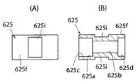
本例の可動子では、直動軸本体及び連結ピースを除いて図4及び図5に示すリニアモータの可動子と同じ構造を有している。そのため、直動軸本体及び連結ピース以外の部材には、図4及び図5に付した符号に600を加えた数の符号を付して、その説明を省略する。図21(A)及び(B)に示すように、本例のリニアモータの連結ピース625の外周部625fの表面は、全体が滑らかな滑面になっている。また、外周部625fには、径方向に対向する2つの矩形の凹部625iが形成されている。図20に示すように、直動軸本体617には、連結ピース625の2つの凹部625iにそれぞれ嵌合する凸部617aが形成されている。凸部617aは、図22に示すように、プレス機Pにより、連結ピース625を嵌合した直動軸本体617をプレスして形成した。連結ピース625と直動軸本体617は、凹部625iと凸部617aとの嵌合により、強固に固定される。
The mover of this example has the same structure as the mover of the linear motor shown in FIGS. 4 and 5 except for the linear motion shaft main body and the connecting piece. For this reason, members other than the linear motion shaft main body and the connecting piece are denoted by the same reference numerals as those in FIGS. 4 and 5 plus 600, and description thereof is omitted. As shown in FIGS. 21A and 21B, the entire outer
本発明によれば、複数のリニアモータユニット全体に対して一組のバックヨーク・アセンブリを組み合わせるだけで複数のリニアモータユニットに容易にバックヨークを取り付けることができる。そのため、リニアモータの製造が容易になる。また、本発明のリニアモータでは、バックヨークをそのまま外部の被取付部材等に取り付ければよいので、複数のリニアモータユニットを支持するブロック状のフレーム及びカバー等の部材を用いる必要がなく、リニアモータの小型化、軽量化を図ることができる。 According to the present invention, the back yoke can be easily attached to the plurality of linear motor units only by combining a set of back yoke assemblies with respect to the entire plurality of linear motor units. This facilitates the production of the linear motor. Further, in the linear motor of the present invention, the back yoke can be directly attached to an external mounted member or the like, so there is no need to use members such as a block-shaped frame and a cover that support a plurality of linear motor units. Can be reduced in size and weight.
1 リニアモータ
3 リニアモータユニット
5 バックヨーク
7 可動子
9 固定子
11 直動軸
13 永久磁石列
17 直動軸本体
19A,19B 一対の直動軸端部材
25 連結ピース
25g 滑面部
25h 粗面部
29 絶縁パイプ
31A〜31I 励磁巻線
31j リード線
33 エンドブラケット
35 軸受
37A,37B 第1及び第2の分割アセンブリ
39 仕切り壁部
DESCRIPTION OF
Claims (8)
前記複数のリニアモータユニットのそれぞれの前記固定子の外側に設けられて、前記複数のリニアモータユニットのそれぞれの磁気回路の一部を構成するバックヨークとを備え、
前記複数のリニアモータユニットは、それぞれの前記直動軸が平行に並ぶように配置されており、
前記バックヨークは、磁性材料からなり、前記複数のリニアモータユニットを全体的に包む包囲部を備えたバックヨーク・アセンブリによって構成されており、
前記固定子は、内部に前記可動子が配置され且つ前記励磁巻線が装着される絶縁パイプを備えており、
前記絶縁パイプの前記軸線方向の両端には、前記直動軸の両端を軸線方向に移動可能に且つ周方向に回転不可能に支持する軸受が固定された一対のエンドブラケットが固定された状態にあり、
前記バックヨーク・アセンブリは、前記一対のエンドブラケットに亘って配置された状態にあり、
前記直動軸は、同じ極性の磁極が向き合うように並べられた複数の前記永久磁石からなる前記永久磁石列が収容される筒状の直動軸本体と、前記直動軸本体の前記軸線方向の両端に接続されて前記軸受にそれぞれ支持される一対の直動軸端部材とからなり、
前記直動軸本体と前記一対の直動軸端部材とは、連結ピースにより連結された状態にあり、
前記直動軸本体は、前記連結ピースの外周部に嵌合されて固定された状態にあり、
前記直動軸端部材は、前記連結ピースの内周部に嵌合されて固定された状態にあり、
前記連結ピースの前記外周部は、前記直動軸本体の長手方向中心側に位置する滑面部と、前記直動軸本体の長手方向中心から離れた側に位置する粗面部とを有しており、
前記直動軸本体の両端部は、接着剤を介して前記滑面部と前記粗面部の両方に接触して配置されていることを特徴とするリニアモータ。 A mover comprising a linear motion shaft that reciprocates in the axial direction and one or more permanent magnet rows composed of a plurality of permanent magnets attached to the linear motion shaft, and the mover reciprocates in the internal space. A plurality of linear motor units each including a stator having a structure in which a plurality of exciting windings formed by winding a winding conductor in a coil shape are arranged along the axis of the linear motion shaft When,
A back yoke that is provided outside the stator of each of the plurality of linear motor units and forms a part of the magnetic circuit of each of the plurality of linear motor units;
The plurality of linear motor units are arranged such that the linear motion axes are arranged in parallel,
The back yoke is made of a magnetic material, and is configured by a back yoke assembly including an enclosing portion that entirely encloses the plurality of linear motor units.
The stator includes an insulating pipe in which the movable element is disposed and the excitation winding is mounted.
A pair of end brackets are fixed to both ends of the insulating pipe in the axial direction. The pair of end brackets are fixed to bearings that support both ends of the linear motion shaft in an axial direction and non-rotatable in the circumferential direction. Yes,
The back yoke assembly is disposed over the pair of end brackets;
The linear motion shaft includes a cylindrical linear motion shaft main body in which the permanent magnet row composed of a plurality of the permanent magnets arranged so that magnetic poles of the same polarity face each other, and the axial direction of the linear motion shaft main body A pair of linear shaft end members connected to both ends of the bearing and supported by the bearings,
The linear motion shaft main body and the pair of linear motion shaft end members are connected by a connection piece,
The linear motion shaft main body is in a state of being fitted and fixed to the outer peripheral portion of the connection piece,
The linear motion shaft end member is in a state of being fitted and fixed to the inner peripheral portion of the connection piece,
The outer peripheral portion of the connection piece has a smooth surface portion located on the longitudinal center side of the linear motion shaft main body and a rough surface portion located on a side away from the longitudinal center of the linear motion shaft main body. ,
Both ends of the linear motion shaft main body are disposed in contact with both the smooth surface portion and the rough surface portion with an adhesive interposed therebetween.
前記仕切り壁部は、前記第1及び第2の分割アセンブリに嵌め合わせ構造を介して固定された状態になっている請求項2に記載のリニアモータ。 The encircling portion of the back yoke assembly is composed of a splittable first and second split assemblies combined such that split surfaces extend in a direction in which the plurality of linear motor units are arranged,
The linear motor according to claim 2, wherein the partition wall portion is fixed to the first and second divided assemblies through a fitting structure.
前記第1及び第2の分割アセンブリの少なくとも一方には、前記リード線が通過する貫通穴が形成されていることを特徴とする請求項3に記載のリニアモータ。 Lead wires for supplying power to the excitation windings are connected to the excitation windings, respectively.
The linear motor according to claim 3, wherein a through-hole through which the lead wire passes is formed in at least one of the first and second divided assemblies.
前記貫通穴の前記軸線方向中心と、前記第1の分割アセンブリまたは前記第2の分割アセンブリの前記軸線方向中心との間の寸法は、1/4τp〜1/2τp(τp=前記複数の永久磁石のピッチ)の範囲内であり、
前記貫通穴の前記軸線方向の長さ寸法が(n−1/2)τp〜(n+1/2)τp
(n=自然数,τp=前記複数の永久磁石のピッチ)であることを特徴とする請求項6に記載のリニアモータ。 The through hole is composed of a slit extending in the axial direction,
The dimension between the axial center of the through hole and the axial center of the first divided assembly or the second divided assembly is 1 / 4τp to 1 / 2τp (τp = the plurality of permanent magnets) Of the pitch)
The length dimension of the through hole in the axial direction is (n−1 / 2) τp to (n + 1/2) τp.
The linear motor according to claim 6, wherein (n = natural number, τp = pitch of the plurality of permanent magnets).
前記直動軸本体の両端部には、前記複数の凹部に嵌合する複数の凸部があることを特徴とする請求項1に記載のリニアモータ。
The outer peripheral portion of the connecting piece has a plurality of recesses,
The linear motor according to claim 1, wherein there are a plurality of convex portions that fit into the plurality of concave portions at both ends of the linear motion shaft main body.
Priority Applications (6)
| Application Number | Priority Date | Filing Date | Title |
|---|---|---|---|
| JP2011142207A JP5981103B2 (en) | 2011-06-27 | 2011-06-27 | Linear motor |
| US13/531,639 US9281734B2 (en) | 2011-06-27 | 2012-06-25 | Linear motor with back yoke |
| EP12275098.7A EP2541745A3 (en) | 2011-06-27 | 2012-06-25 | Linear Motor With Back Yoke |
| CN201210213886.9A CN102857064B (en) | 2011-06-27 | 2012-06-25 | Linear motor |
| KR1020120068644A KR20130001698A (en) | 2011-06-27 | 2012-06-26 | Linear motor |
| TW101122994A TWI555311B (en) | 2011-06-27 | 2012-06-27 | Linear motor |
Applications Claiming Priority (1)
| Application Number | Priority Date | Filing Date | Title |
|---|---|---|---|
| JP2011142207A JP5981103B2 (en) | 2011-06-27 | 2011-06-27 | Linear motor |
Publications (2)
| Publication Number | Publication Date |
|---|---|
| JP2013009563A JP2013009563A (en) | 2013-01-10 |
| JP5981103B2 true JP5981103B2 (en) | 2016-08-31 |
Family
ID=46395554
Family Applications (1)
| Application Number | Title | Priority Date | Filing Date |
|---|---|---|---|
| JP2011142207A Expired - Fee Related JP5981103B2 (en) | 2011-06-27 | 2011-06-27 | Linear motor |
Country Status (6)
| Country | Link |
|---|---|
| US (1) | US9281734B2 (en) |
| EP (1) | EP2541745A3 (en) |
| JP (1) | JP5981103B2 (en) |
| KR (1) | KR20130001698A (en) |
| CN (1) | CN102857064B (en) |
| TW (1) | TWI555311B (en) |
Families Citing this family (4)
| Publication number | Priority date | Publication date | Assignee | Title |
|---|---|---|---|---|
| JP6166926B2 (en) * | 2013-03-26 | 2017-07-19 | 山洋電気株式会社 | Linear motor |
| JP2022189466A (en) * | 2021-06-11 | 2022-12-22 | 山洋電気株式会社 | linear head module |
| JP2022189465A (en) * | 2021-06-11 | 2022-12-22 | 山洋電気株式会社 | Linear motor and linear head module |
| JP2022189464A (en) | 2021-06-11 | 2022-12-22 | 山洋電気株式会社 | linear head module |
Family Cites Families (20)
| Publication number | Priority date | Publication date | Assignee | Title |
|---|---|---|---|---|
| US3471729A (en) * | 1966-02-10 | 1969-10-07 | Controls Co Of America | Plural motor assembly |
| JPS5427527Y2 (en) * | 1974-07-03 | 1979-09-07 | ||
| CA1122638A (en) * | 1979-03-13 | 1982-04-27 | Cts Corporation | Linear electromagnetic actuator with permanent magnet armature |
| CN85200996U (en) * | 1985-04-01 | 1986-01-15 | 陕西师范大学 | Linear tubing motor easy to be assemblyed or disassemblyed |
| JPH07322595A (en) * | 1994-05-24 | 1995-12-08 | Shicoh Eng Co Ltd | Linear d.c. motor |
| JP3481759B2 (en) * | 1995-12-18 | 2003-12-22 | Tdk株式会社 | Permanent magnet linear motor |
| DE10244261B4 (en) * | 2002-09-24 | 2007-03-29 | Festo Ag & Co. | Coil system, in particular for an electrodynamic linear direct drive |
| JP4220880B2 (en) * | 2003-10-17 | 2009-02-04 | 住友重機械工業株式会社 | Waterproof terminal block unit |
| US7378765B2 (en) * | 2004-08-09 | 2008-05-27 | Oriental Motor Co., Ltd. | Cylinder-type linear motor and moving part thereof |
| JP4711181B2 (en) * | 2005-01-17 | 2011-06-29 | 株式会社安川電機 | Cylindrical linear motor armature coil winding method, cylindrical linear motor stator, and cylindrical linear motor using the same |
| JP2007043780A (en) * | 2005-08-01 | 2007-02-15 | Konica Minolta Medical & Graphic Inc | Shaft type linear motor and radiograph reader |
| CN101292414B (en) * | 2005-10-21 | 2011-01-19 | 株式会社安川电机 | Circular cylindrical linear motor |
| JP4385406B2 (en) * | 2005-10-21 | 2009-12-16 | 株式会社安川電機 | Linear head module |
| JP4756472B2 (en) * | 2006-05-11 | 2011-08-24 | 株式会社安川電機 | Manufacturing method of cylindrical linear motor field part and cylindrical linear motor |
| JP2008086144A (en) * | 2006-09-28 | 2008-04-10 | Murata Mach Ltd | Linear motor and machine tool having the motor mounted thereon |
| JP5276299B2 (en) * | 2007-10-19 | 2013-08-28 | 日本トムソン株式会社 | Mounting head with built-in shaft type linear motor |
| JP5254651B2 (en) * | 2008-03-28 | 2013-08-07 | Thk株式会社 | Linear motor with magnetic shield plate, multi-axis linear motor with magnetic shield plate, and method for manufacturing linear motor with magnetic shield plate |
| JP2010288418A (en) * | 2009-06-15 | 2010-12-24 | Tamagawa Seiki Co Ltd | Cylindrical linear motor |
| JP5646476B2 (en) * | 2009-06-29 | 2014-12-24 | Thk株式会社 | Actuator |
| JP5345047B2 (en) * | 2009-12-04 | 2013-11-20 | 三菱電機株式会社 | Linear motor |
-
2011
- 2011-06-27 JP JP2011142207A patent/JP5981103B2/en not_active Expired - Fee Related
-
2012
- 2012-06-25 EP EP12275098.7A patent/EP2541745A3/en not_active Withdrawn
- 2012-06-25 US US13/531,639 patent/US9281734B2/en active Active
- 2012-06-25 CN CN201210213886.9A patent/CN102857064B/en not_active Expired - Fee Related
- 2012-06-26 KR KR1020120068644A patent/KR20130001698A/en not_active Application Discontinuation
- 2012-06-27 TW TW101122994A patent/TWI555311B/en not_active IP Right Cessation
Also Published As
| Publication number | Publication date |
|---|---|
| US9281734B2 (en) | 2016-03-08 |
| TW201320554A (en) | 2013-05-16 |
| TWI555311B (en) | 2016-10-21 |
| CN102857064B (en) | 2016-08-03 |
| CN102857064A (en) | 2013-01-02 |
| JP2013009563A (en) | 2013-01-10 |
| US20120326537A1 (en) | 2012-12-27 |
| KR20130001698A (en) | 2013-01-04 |
| EP2541745A2 (en) | 2013-01-02 |
| EP2541745A3 (en) | 2016-11-09 |
Similar Documents
| Publication | Publication Date | Title |
|---|---|---|
| JP5981104B2 (en) | Linear motor | |
| US11289956B2 (en) | Rotating electric device | |
| JP4860222B2 (en) | Linear motor and manufacturing method thereof | |
| KR100785192B1 (en) | Coreless linear motor | |
| JP5981103B2 (en) | Linear motor | |
| JP5438498B2 (en) | Linear synchronous motor | |
| KR101897637B1 (en) | Linear motor | |
| US8487485B2 (en) | Linear synchronous motor | |
| TW201036308A (en) | Linear synchronous motor | |
| JP2010213546A (en) | Canned linear motor armature and canned linear motor | |
| JP2007068326A (en) | Linear motor unit and method of combining same | |
| KR20220109963A (en) | Terminal block for motor | |
| JP5755890B2 (en) | Linear motor and manufacturing method thereof | |
| US11462981B2 (en) | Electric motor | |
| JP4711182B2 (en) | Linear motor armature and linear motor | |
| CN103427505B (en) | Motor | |
| JP2012147517A (en) | Linear motor device and linear motor | |
| JP2009011157A (en) | Linear motor unit and combination method of the same | |
| JP2011193553A (en) | Coreless linear motor of two-degrees-of-freedom |
Legal Events
| Date | Code | Title | Description |
|---|---|---|---|
| A621 | Written request for application examination |
Free format text: JAPANESE INTERMEDIATE CODE: A621 Effective date: 20140213 |
|
| A977 | Report on retrieval |
Free format text: JAPANESE INTERMEDIATE CODE: A971007 Effective date: 20141119 |
|
| A131 | Notification of reasons for refusal |
Free format text: JAPANESE INTERMEDIATE CODE: A131 Effective date: 20141224 |
|
| A521 | Written amendment |
Free format text: JAPANESE INTERMEDIATE CODE: A523 Effective date: 20150223 |
|
| A131 | Notification of reasons for refusal |
Free format text: JAPANESE INTERMEDIATE CODE: A131 Effective date: 20150818 |
|
| A521 | Written amendment |
Free format text: JAPANESE INTERMEDIATE CODE: A523 Effective date: 20151006 |
|
| A131 | Notification of reasons for refusal |
Free format text: JAPANESE INTERMEDIATE CODE: A131 Effective date: 20160216 |
|
| A521 | Written amendment |
Free format text: JAPANESE INTERMEDIATE CODE: A523 Effective date: 20160226 |
|
| TRDD | Decision of grant or rejection written | ||
| A01 | Written decision to grant a patent or to grant a registration (utility model) |
Free format text: JAPANESE INTERMEDIATE CODE: A01 Effective date: 20160712 |
|
| A61 | First payment of annual fees (during grant procedure) |
Free format text: JAPANESE INTERMEDIATE CODE: A61 Effective date: 20160728 |
|
| R150 | Certificate of patent or registration of utility model |
Ref document number: 5981103 Country of ref document: JP Free format text: JAPANESE INTERMEDIATE CODE: R150 |
|
| R250 | Receipt of annual fees |
Free format text: JAPANESE INTERMEDIATE CODE: R250 |
|
| LAPS | Cancellation because of no payment of annual fees |