JP5980558B2 - Rail fastening / relaxation method for machine construction and rail fastening / relaxation device for machine construction - Google Patents
Rail fastening / relaxation method for machine construction and rail fastening / relaxation device for machine construction Download PDFInfo
- Publication number
- JP5980558B2 JP5980558B2 JP2012105668A JP2012105668A JP5980558B2 JP 5980558 B2 JP5980558 B2 JP 5980558B2 JP 2012105668 A JP2012105668 A JP 2012105668A JP 2012105668 A JP2012105668 A JP 2012105668A JP 5980558 B2 JP5980558 B2 JP 5980558B2
- Authority
- JP
- Japan
- Prior art keywords
- rail
- fastening
- machine construction
- relaxation
- rail fastening
- Prior art date
- Legal status (The legal status is an assumption and is not a legal conclusion. Google has not performed a legal analysis and makes no representation as to the accuracy of the status listed.)
- Expired - Fee Related
Links
Images


Description
本発明は、機械施工用レール締結・緩解方法及び機械施工用レール締結・緩解装置に関するものである。 The present invention relates to a rail fastening / relaxation method for machine construction and a rail fastening / relaxation device for machine construction.
従来、レール締結・緩解装置としては、十分な敷設延長・実績がある直結系軌道に適用される締結・緩解装置(下記特許文献1参照)があるが、レール交換時の保守作業(レール締結・緩解装置の締結ボルト・ナットの緊緩、レール交換時に支障とならない仮置き=プリセット)は人力に因るところが大きい。 Conventionally, as a rail fastening / relaxation device, there is a fastening / relaxation device (refer to Patent Document 1 below) applied to a directly connected track with sufficient laying extension and track record. The tightening of fastening bolts and nuts of the loosening device and temporary placement (preset) that does not hinder the rail replacement are largely due to human power.
また、同レール締結・緩解装置については、板ばねを締結ボルト・ナットで固定する方式であるため、レール締結・緩解装置の緊締状態を一定に保つために締結ボルト・ナットのトルク管理が必須となる。 The rail fastening / relaxation device is a system in which the leaf springs are fixed with fastening bolts and nuts, so torque management of the fastening bolts and nuts is indispensable in order to keep the tightening state of the rail fastening / relaxation devices constant. Become.
図4は従来のレール締結・緩解装置を示す図である。 FIG. 4 is a view showing a conventional rail fastening / relaxing device.
この図において、100はスラブ、101は絶縁板、102はタイプレート、103はタイプレート102のショルダー部、104はレール、105は締結ボルト、106はナット、107は座金、108は板ばねである。
In this figure, 100 is a slab, 101 is an insulating plate, 102 is a tie plate, 103 is a shoulder portion of the
しかしながら、上述したように、従来の直結系軌道向けのレール締結・緩解装置は人力施工を前提として設計されているため、機械施工に対応させるためには板ばねの形状や締結ボルトの構造等を新たに提案する必要があった。また、現行のトルク管理にかかる労力を低減するため、レール締結・緩解装置の緊締状態をモニタリングする新しい管理手法を提案する必要があった。 However, as described above, since the conventional rail fastening / relaxation device for directly connected tracks is designed on the premise of manual construction, the shape of the leaf spring, the structure of the fastening bolt, etc. are required in order to correspond to the machine construction. It was necessary to make a new proposal. In addition, in order to reduce the labor required for current torque management, it was necessary to propose a new management method for monitoring the tightening state of the rail fastening / relaxation device.
そこで、本願発明者らは、既に機械施工用レール締結・緩解方法及び装置(上記した特許文献2,3)を提案し、特許出願を行った。
Therefore, the inventors of the present application have already proposed a rail fastening / relaxation method and apparatus for machine construction (
しかし、その先行特許出願では、レールの底部側面と締結ボルトとの間には空間が生じるため、機械施工用レール締結・緩解においては、締結ボルトプリセット時のシフト量を確実に設定し、レール締結・緩解を安定かつ円滑に行うには難があった。 However, in that prior patent application, there is a space between the bottom side surface of the rail and the fastening bolt. Therefore, in the rail fastening for machine construction, the shift amount at the time of fastening bolt preset is set securely and the rail fastening.・ There was difficulty in carrying out remission stably and smoothly.
本発明は、上記状況に鑑みて、機械施工に適応した好適な形状を有する締結ボルトを用いた機械施工用レール締結・緩解方法及び機械施工用レール締結・緩解装置を提供することを目的とする。 In view of the above circumstances, an object of the present invention is to provide a rail fastening / relaxation method for machine construction and a rail fastening / relaxation device for machine construction using a fastening bolt having a suitable shape adapted to the machine construction. .
本発明は、上記目的を達成するために、
〔1〕機械施工用レール締結・緩解方法において、締結ボルトの底部のレール側に突出した突出部を形成し、この突出部をレールの底部側面に当接させ、前記締結ボルトのプリセット時のシフト量を設定し、機械化施工によるレール締結・緩解を行うことを特徴とする。
In order to achieve the above object, the present invention provides
[1] In the rail fastening / relaxation method for machine construction, a protrusion protruding to the rail side of the bottom of the fastening bolt is formed, and this protrusion is brought into contact with the side of the bottom of the rail to shift the fastening bolt at the preset time. The amount is set, and the rail fastening / relaxation is performed by mechanized construction.
〔2〕上記〔1〕記載の機械施工用レール締結・緩解方法において、前記シフト量を7mmとしたことを特徴とする。 [2] In the rail fastening / relaxing method for machine construction described in [1], the shift amount is 7 mm.
〔3〕機械施工用レール締結・緩解装置において、底部のレール側に突出した突出部を有し、この突出部をレールの底部側面に当接させ、プリセット時のシフト量を適切に設定し、機械化施工によるレール締結・緩解を行う締結ボルトを具備することを特徴とする。 [ 3 ] In the machine construction rail fastening / relaxation device, the bottom portion has a protruding portion that protrudes toward the rail side, and this protruding portion is brought into contact with the bottom side surface of the rail to appropriately set the shift amount at the time of presetting. It is characterized by comprising fastening bolts that perform rail fastening and loosening by mechanized construction.
〔4〕上記〔3〕記載の機械施工用レール締結・緩解装置において、前記締結ボルトのシフト量が7mmであることを特徴とする。 [ 4 ] The rail fastening / relaxing device for machine construction described in [ 3 ] above, wherein a shift amount of the fastening bolt is 7 mm.
本発明によれば、締結ボルトのプリセット時のシフト量を確実に設定するとともに、機械施工によるレール締結・緩解を安定かつ確実にすることができる。 ADVANTAGE OF THE INVENTION According to this invention, while setting the amount of shifting at the time of the preset of a fastening bolt reliably, the rail fastening and loosening by machine construction can be made stable and reliable.
本発明の機械施工用レール締結・緩解方法は、締結ボルトの底部のレール側に突出した突出部を形成し、この突出部をレールの底部側面に当接させ、前記締結ボルトのプリセット時のシフト量を設定し、機械化施工によるレール締結・緩解を行う。 In the rail fastening / relaxing method for machine construction according to the present invention, a projecting portion projecting to the rail side of the bottom portion of the fastening bolt is formed, the projecting portion is brought into contact with the bottom side surface of the rail, and the fastening bolt is shifted when presetting. Set the amount, and tighten and relieve the rail by mechanized construction.
以下、本発明の実施の形態について詳細に説明する。 Hereinafter, embodiments of the present invention will be described in detail.
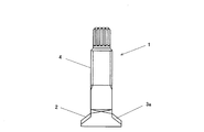
図1は本発明の実施例を示す機械施工用レール締結・緩解装置のレール横断方向の締結ボルトの形状を示す図、図2はそのレール敷設方向の締結ボルトの形状を示す図、図3は締結ボルトのプリセット時の模式図である。 FIG. 1 is a diagram showing the shape of a fastening bolt in the rail transverse direction of a rail fastening / relaxing device for machine construction showing an embodiment of the present invention, FIG. 2 is a diagram showing the shape of the fastening bolt in the rail laying direction, and FIG. It is a schematic diagram at the time of preset of a fastening bolt.
これらの図において、1は締結ボルト(トルシア形高力ボルト)、2は締結ボルト1の底部、3は底部2のレール側に7mm突出した突出部であり、この突出部3は傾斜曲面3aを有している。上方にはナット6が螺合する雄螺子部4と上端にピンテール5を備えている。7はタイプレート、8はタイプレートショルダー部、9は締結ばね、10はレール、10Aはレールの底部側面である。
In these drawings, 1 is the fastening bolts (torque shear-type high-strength bolts), 2 the bottom of the
機械化施工によれば、締結ボルト1のピンテール5を機械装置先端に取り付けた電動レンチのインナーソケットで掴み、ナット6の締付、緩解および位置調整を行う。なお、締結ボルトであるトルシア形高力ボルトのピンテールの形状寸法は、JSSII−09(構造用トルシア形高力ボルト、六角ナット、平座金のセット)に規定されている。
According to the mechanized construction, the pin tail 5 of the fastening bolt 1 is grasped by the inner socket of the electric wrench attached to the tip of the mechanical device, and the
特に、図3に示すように、締結ボルト1のプリセット時にシフト量11が必要となるので、本発明では、締結ボルト1にはレール10側に7mm突出した突出部3を形成して、この突出部3をレールの底部側面10Aに当接させてシフト量11を確保して、機械化施工によるレール締結・緩解を安定かつ確実に行うことができるようにした。
In particular, as shown in FIG. 3, when the fastening bolt 1 is preset, a
また、締結ボルト1の底部2の突出部3は傾斜曲面3aを有しているので、締結ボルト1のタイプレート7のタイプレートショルダー部8への係合が円滑に行われる。
Further, the protruding
本実施例では、締結ボルト1の底部2に7mm突出した突出部3を形成し、突出部3に傾斜曲面3aを有している場合を例示したが、本形状寸法は、タイプレートショルダー部8aおよび締結ボルト1の形状寸法により、変化させることができるものであり、ここに示した突出量7mm、傾斜曲面に必ずしも限定されるものではない。
In this embodiment, to form a projecting
なお、本発明は上記実施例に限定されるものではなく、本発明の趣旨に基づき種々の変形が可能であり、これらを本発明の範囲から排除するものではない。 In addition, this invention is not limited to the said Example, Based on the meaning of this invention, a various deformation | transformation is possible and these are not excluded from the scope of the present invention.
本発明の機械施工用レール締結・緩解方法は、締結ボルトのプリセット時にシフト量が必要となるので、レール側に突出した突出部を形成して、この突出部をレールの底部側面に当接させ、シフト量を確保するとともに、機械化施工が安定かつ確実に行われるようにした機械施工用レール締結・緩解方法として利用可能である。 The rail fastening / relaxation method for machine construction according to the present invention requires a shift amount at the time of fastening bolt presetting. Therefore, a protruding portion protruding to the rail side is formed, and this protruding portion is brought into contact with the bottom side surface of the rail. It can be used as a rail fastening / relaxation method for machine construction that secures the shift amount and that allows mechanized construction to be performed stably and reliably.
1 締結ボルト(トルシア形高力ボルト)
2 締結ボルトの底部
3 突出部
3a 傾斜曲面
4 雄螺子部
5 ピンテール
6 ナット
7 タイプレート
8 タイプレートショルダー部
9 締結ばね
10 レール
10A レールの底部側面
11 シフト量
1 Fastening bolt (Torsia type high strength bolt)
2 bottom part of fastening
Claims (4)
Priority Applications (1)
| Application Number | Priority Date | Filing Date | Title |
|---|---|---|---|
| JP2012105668A JP5980558B2 (en) | 2012-05-07 | 2012-05-07 | Rail fastening / relaxation method for machine construction and rail fastening / relaxation device for machine construction |
Applications Claiming Priority (1)
| Application Number | Priority Date | Filing Date | Title |
|---|---|---|---|
| JP2012105668A JP5980558B2 (en) | 2012-05-07 | 2012-05-07 | Rail fastening / relaxation method for machine construction and rail fastening / relaxation device for machine construction |
Publications (2)
| Publication Number | Publication Date |
|---|---|
| JP2013234435A JP2013234435A (en) | 2013-11-21 |
| JP5980558B2 true JP5980558B2 (en) | 2016-08-31 |
Family
ID=49760758
Family Applications (1)
| Application Number | Title | Priority Date | Filing Date |
|---|---|---|---|
| JP2012105668A Expired - Fee Related JP5980558B2 (en) | 2012-05-07 | 2012-05-07 | Rail fastening / relaxation method for machine construction and rail fastening / relaxation device for machine construction |
Country Status (1)
| Country | Link |
|---|---|
| JP (1) | JP5980558B2 (en) |
Families Citing this family (1)
| Publication number | Priority date | Publication date | Assignee | Title |
|---|---|---|---|---|
| JP2014205976A (en) * | 2013-04-11 | 2014-10-30 | 公益財団法人鉄道総合技術研究所 | Fastening bolt structure for rail fastening device, coping with mechanical construction |
Family Cites Families (3)
| Publication number | Priority date | Publication date | Assignee | Title |
|---|---|---|---|---|
| JPS54146307A (en) * | 1978-05-09 | 1979-11-15 | Tetsudo Kizai Kogyo Co Ltd | Rail variable coupler |
| JPH047202Y2 (en) * | 1986-03-25 | 1992-02-26 | ||
| JP2887720B2 (en) * | 1992-10-21 | 1999-04-26 | 財団法人鉄道総合技術研究所 | Level crossing pavement |
-
2012
- 2012-05-07 JP JP2012105668A patent/JP5980558B2/en not_active Expired - Fee Related
Also Published As
| Publication number | Publication date |
|---|---|
| JP2013234435A (en) | 2013-11-21 |
Similar Documents
| Publication | Publication Date | Title |
|---|---|---|
| JP3200554U (en) | Mechanical automatic fastening bolt | |
| KR101050490B1 (en) | Elastic clip for railroad rail fixing and this establishment method | |
| CN203632599U (en) | Photovoltaic support system fixing assembly | |
| CN201128128Y (en) | Quick-speed torque wrench | |
| JP5980558B2 (en) | Rail fastening / relaxation method for machine construction and rail fastening / relaxation device for machine construction | |
| CN105114436A (en) | Interlocked stop nut assembly | |
| US8529180B1 (en) | Super spike | |
| CN101922496A (en) | Bolt and bolt connecting structure thereof | |
| CN205651096U (en) | Key doubling machine supplementary fixed knot construct | |
| JP2007132414A (en) | Method of manufacturing connecting rod | |
| JP2007271032A (en) | Bolt joint structure | |
| CN103311492A (en) | Wiring terminal of storage battery | |
| CN104742054B (en) | It is a kind of can fishbolt head spanner | |
| KR20130038490A (en) | A tool of railway rail | |
| JP5980505B2 (en) | Rail fastening / relaxation method for machine construction and its rail fastening / relaxation device | |
| CN203161966U (en) | Regulating and locking device for rope end of steel wire rope | |
| JP3150380U (en) | Temporary bolt for regeneration | |
| CN201333675Y (en) | Special wrench for cover of drain pipe inspection port | |
| CN107131201A (en) | Bolt end retention device | |
| CN202612353U (en) | Anti-thief fastener | |
| CN102705347B (en) | Method for preventing fastening piece from being illegally opened, anti-theft fastening piece and special spanner | |
| WO2012122829A1 (en) | Self-tightening lock nut | |
| JP5872893B2 (en) | Rail fastening / relaxation method for machine construction and its rail fastening / relaxation device | |
| JP2014205976A (en) | Fastening bolt structure for rail fastening device, coping with mechanical construction | |
| CN102003436A (en) | Fixing clamp for power engineering |
Legal Events
| Date | Code | Title | Description |
|---|---|---|---|
| A621 | Written request for application examination |
Free format text: JAPANESE INTERMEDIATE CODE: A621 Effective date: 20140908 |
|
| A977 | Report on retrieval |
Free format text: JAPANESE INTERMEDIATE CODE: A971007 Effective date: 20150522 |
|
| A131 | Notification of reasons for refusal |
Free format text: JAPANESE INTERMEDIATE CODE: A131 Effective date: 20150616 |
|
| A521 | Request for written amendment filed |
Free format text: JAPANESE INTERMEDIATE CODE: A523 Effective date: 20150810 |
|
| A131 | Notification of reasons for refusal |
Free format text: JAPANESE INTERMEDIATE CODE: A131 Effective date: 20160112 |
|
| A521 | Request for written amendment filed |
Free format text: JAPANESE INTERMEDIATE CODE: A523 Effective date: 20160219 |
|
| TRDD | Decision of grant or rejection written | ||
| A01 | Written decision to grant a patent or to grant a registration (utility model) |
Free format text: JAPANESE INTERMEDIATE CODE: A01 Effective date: 20160726 |
|
| A61 | First payment of annual fees (during grant procedure) |
Free format text: JAPANESE INTERMEDIATE CODE: A61 Effective date: 20160727 |
|
| R150 | Certificate of patent or registration of utility model |
Ref document number: 5980558 Country of ref document: JP Free format text: JAPANESE INTERMEDIATE CODE: R150 |
|
| R250 | Receipt of annual fees |
Free format text: JAPANESE INTERMEDIATE CODE: R250 |
|
| LAPS | Cancellation because of no payment of annual fees |