JP5980552B2 - Massage machine - Google Patents
Massage machine Download PDFInfo
- Publication number
- JP5980552B2 JP5980552B2 JP2012094450A JP2012094450A JP5980552B2 JP 5980552 B2 JP5980552 B2 JP 5980552B2 JP 2012094450 A JP2012094450 A JP 2012094450A JP 2012094450 A JP2012094450 A JP 2012094450A JP 5980552 B2 JP5980552 B2 JP 5980552B2
- Authority
- JP
- Japan
- Prior art keywords
- rotation
- support
- support member
- holding means
- rotating
- Prior art date
- Legal status (The legal status is an assumption and is not a legal conclusion. Google has not performed a legal analysis and makes no representation as to the accuracy of the status listed.)
- Expired - Fee Related
Links
Images





Landscapes
- Massaging Devices (AREA)
Description
本発明はマッサージ機に関する。 The present invention relates to a massage machine.
従来、支持台221及び支持台221に対して回動可能な一対の回動板226,227よりなる支持具220と、回動板226,227の互いに対向する面側に設けた回動手段としてのエアーバッグ231,232と、を備え、回動手段により回動板226,227を回動させることによって、互いに対向するエアーバッグ231,232の押圧面の離間距離および押圧方向を調節することができる(すなわち、支持具220の姿勢を変更できる)エアーマッサージ器Aが知られている(例えば、特許文献1の図8参照)。 Conventionally, as a support tool 221 composed of a support base 221 and a pair of rotary plates 226 and 227 that can be rotated with respect to the support base 221, and a rotating means provided on the mutually facing surfaces of the rotary plates 226 and 227 Air bags 231 and 232, and by rotating the rotating plates 226 and 227 by the rotating means, the separation distance and the pressing direction of the pressing surfaces of the air bags 231 and 232 facing each other can be adjusted. There is known an air massager A that can be used (that is, the posture of the support 220 can be changed) (see, for example, FIG. 8 of Patent Document 1).
また、底壁部17と、底壁部17に対して折畳姿勢と使用姿勢との間で回動可能な一対の側壁部18と、を備えた足支持部材5が知られている(例えば、特許文献2の図4〜図6参照)。
Further, there is known a
しかし、上記特許文献1に開示されたエアーマッサージ器Aは、支持台221と回動板226,227との間に介在させたエアーバッグ230,233により回動板226,227を回動させて位置を保持させる構成であるため、エアーバッグ230,233を背面側から支える支持台221の構成が必須となる。つまり、支持台221及びエアーバッグ230,233により、回動板230,233を所望の位置で保持(固定)する回動保持手段を構成している。従って、部品点数が増加する上、装置が大型化してしまう。
However, the air massager A disclosed in
一方、上記特許文献2の図5及び図6に開示された足支持部材5は、回動手段を背面側から支える部材を必要とせず装置が小型である。しかし、側壁部18が底壁部17に対して使用姿勢(図5の状態)において、側壁部18は外側への回動は規制されているものの内側への回動は規制されておらず、側壁部18の位置を保持することができない。
On the other hand, the
また、上記特許文献2の図4に開示された足支持部材5は、側壁部18に外端部を連結したアクチュエータ33(回動手段)により側壁部18を回動させることができる。しかし、上記特許文献1と同様、アクチュエータ33の内端部を支持するための部材が必要となり装置が大型化する上、使用姿勢へと状態遷移させると、アクチュエータ33が底壁部17内に侵入する構造であるため底壁部17の構造が複雑化してしまう。
Further, the
本発明は、上述した問題を解消するためになされたものであり、簡単な構造で身体支持具の姿勢を変更及び維持することが可能であって、身体支持具を小型化したマッサージ機を提供することを目的とする。 The present invention has been made to solve the above-described problems, and provides a massage machine that can change and maintain the posture of a body support tool with a simple structure, and that can reduce the size of the body support tool. The purpose is to do.
本第1発明は、被施療者の身体を支持する身体支持面を有する支持部材と、前記支持部材の左右方向の端部を回動支点として回動可能に取り付けられた回動部材と、からなる身体支持具と、前記支持部材の身体支持面又は前記回動部材の載置面の裏側面に設けられたマッサージ具と、前記回動部材を所望の角度に調節して保持する回動保持手段と、を備え、前記支持部材は、前記回動部材の回動範囲を規制するストッパーを有し、前記回動保持手段は、前記支持部材の側部に設けられ、前記回動部材と一体的に回動可能であり、前記回動部材の載置面の裏側面が前記支持部材の身体支持面に重なって前記身体支持具が略平坦となる第1位置と、前記回動部材の載置面の裏側面が前記支持部材の身体支持面に対して略垂直となる第2位置と、の少なくとも2つの位置で前記回動部材を保持可能であることを特徴とする。
このような構成とすることにより、回動保持手段が支持部材の側部に設けられているため、回動保持手段が支持部材の内部に侵入することがなく身体支持具の構造を簡素化することができる。また、回動保持手段が回動部材と一体的に回動可能であるため、回動保持手段を背面側から支える部材を別途必要とせず、身体支持具をコンパクトに作製することができる。
また、支持部材と回動部材との間にストッパーを設けるだけで、第2位置にある回動部材が更に外側に移動することを防止でき、簡単な構造で回動部材を第2位置で保持することができる。
The first invention includes a support member having a body support surface that supports the body of the user, and a rotation member that is rotatably attached with a left and right end portion of the support member as a rotation fulcrum. A body support device, a massage device provided on a body support surface of the support member or a back side surface of the mounting surface of the rotation member, and a rotation holding for adjusting and holding the rotation member at a desired angle And the support member has a stopper for restricting the rotation range of the rotation member, and the rotation holding means is provided on a side portion of the support member, and is integrated with the rotation member. A first position where the back surface of the mounting surface of the rotating member overlaps the body supporting surface of the supporting member , and the body supporting tool is substantially flat, and the mounting of the rotating member . and a second position which is substantially perpendicular to the body-supporting surface of the back surface the support member surface, the Even without, characterized in that it is capable of holding the rotating member in two positions.
With this configuration, since the rotation holding means is provided on the side portion of the support member, the rotation holding means does not enter the inside of the support member, and the structure of the body support tool is simplified. be able to. Moreover, since the rotation holding means can be rotated integrally with the rotation member, a member for supporting the rotation holding means from the back side is not required separately, and the body support can be made compact.
Moreover, it is possible to prevent the rotating member at the second position from moving further outward by simply providing a stopper between the support member and the rotating member, and the rotating member is held at the second position with a simple structure. can do.
本第2発明は、被施療者の身体を支持する身体支持面を有する支持部材と、前記支持部材の左右方向の端部を回動支点として回動可能に取り付けられた回動部材と、からなる身体支持具と、前記支持部材の身体支持面又は前記回動部材の載置面の裏側面に設けられたマッサージ具と、前記回動部材を所望の角度に調節して保持するための複数のラッチ部を有する回動保持手段と、を備え、前記回動保持手段は、前記回動支点の近傍に設けられており、前記回動部材の載置面の裏側面が前記支持部材の身体支持面に対して略垂直となる第2位置と、前記回動部材の載置面の裏側面が前記支持部材の身体支持面に対して展開して前記身体支持具が略平坦となる第3位置と、の少なくとも2つの位置で前記回動部材を保持可能であることを特徴とする。
このような構成とすることにより、回動保持手段を背面側から支える部材を別途必要とせず、部品点数を削減できる上、身体支持具をコンパクトに作製することができる。また、身体を身体支持面から退避させることなく、回動部材の位置調節を行うことができる。
The second invention comprises a support member having a body support surface that supports the body of the user, and a rotating member that is rotatably attached with the end in the left-right direction of the support member as a rotation fulcrum. and body support comprising a massaging device which is provided on the back surface of the mounting surface of the body supporting surface or said rotating member of said support member, a plurality for holding and adjusting said rotating member at a desired angular A rotation holding means having a latch portion , wherein the rotation holding means is provided in the vicinity of the rotation fulcrum, and a back side surface of the mounting surface of the rotation member is a body of the support member . A second position that is substantially perpendicular to the support surface and a rear side surface of the mounting surface of the rotating member expands with respect to the body support surface of the support member , so that the body support is substantially flat. The rotating member can be held at at least two positions. .
By adopting such a configuration, a member for supporting the rotation holding means from the back side is not required separately, the number of parts can be reduced, and the body support can be made compact. Further, the position of the rotating member can be adjusted without retracting the body from the body support surface.
また、前記回動保持手段は、前記第1位置又は前記第3位置と、前記第2位置との間の複数位置で前記回動部材を保持できることが好ましい。
このような構成とすることにより、回動部材の位置調節幅が広がり、被施療者の好みにより対応することができる。例えば、マッサージ具によるマッサージ力や施療位置を調節することができる。
Moreover, it is preferable that the said rotation holding means can hold | maintain the said rotation member in the several position between the said 1st position or the said 3rd position, and the said 2nd position.
By adopting such a configuration, the position adjustment range of the rotating member is widened, and it is possible to cope with the preference of the user. For example, the massage force and the treatment position by the massage tool can be adjusted.
また、前記回動保持手段は、ラチェット機構により構成されていることが好ましい。
このような構成とすることにより、簡単な構造で回動部材を複数位置に調節することができる。
Moreover, it is preferable that the said rotation holding means is comprised by the ratchet mechanism.
With such a configuration, the rotating member can be adjusted to a plurality of positions with a simple structure.
また、前記回動部材が前記第1位置に位置するときには前記マッサージ具を非作動状態とする制御手段を備えたことが好ましい。
このような構成とすることにより、身体支持面と施療面が略対向状態(支持部材と回動部材が重なった状態)のときにマッサージ具が作動することを防止できる。
In addition, it is preferable that a control unit that deactivates the massage device when the rotating member is located at the first position is provided.
By setting it as such a structure, it can prevent that a massage tool act | operates when a body support surface and a treatment surface are the substantially opposing states (state in which the support member and the rotation member overlapped).
また、前記回動部材は、左右で対をなし、左右別々に角度調節及び保持できることが好ましい。
このような構成とすることにより、対の回動部材の位置をそれぞれ調節することができる。また、回動部材にマッサージ具を設けた場合は、左半身と右半身のそれぞれに対して所望する位置をマッサージすることができる。
In addition, it is preferable that the rotating members are paired on the left and right sides, and can be adjusted and held on the left and right separately.
By setting it as such a structure, the position of a pair of rotation member can be adjusted, respectively. Moreover, when a massage tool is provided on the rotating member, a desired position can be massaged for each of the left half body and the right half body.
また、前記回動部材は、左右で対をなし、左右連動して角度調節及び保持できることが好ましい。
このような構成とすることにより、対の回動部材の位置を左右対称に保ったまま、対の回動部材の離間距離を調節することができる。
Further, it is preferable that the rotating members are paired on the left and right sides, and can be adjusted and held in an interlocking manner with the left and right.
By adopting such a configuration, it is possible to adjust the separation distance of the pair of rotation members while keeping the position of the pair of rotation members symmetrical.
本発明によれば、簡単な構造で身体支持具の姿勢を変更及び維持することが可能であって、身体支持具を小型化することができる。 According to the present invention, the posture of the body support tool can be changed and maintained with a simple structure, and the body support tool can be downsized.
[第1実施形態]
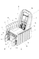
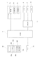
以下、本発明の第1実施形態(本第1発明)に係るマッサージ機1の全体構成について、図1〜図3に基づいて説明する。図1は、フットレスト4を第1位置としたマッサージ機1の斜視図である。図2は、フットレスト4を第2位置としたマッサージ機1の斜視図である。図3は、マッサージ機1の機能ブロック図である。
[First embodiment]
Hereinafter, the whole structure of the
[マッサージ機の全体構成]
図1に示すとおり、本発明の第1実施形態に係るマッサージ機1は、被施療者の身体を支持する身体支持具として、被施療者が着座する座部2、座部2の後端部に設けられた被施療者が凭れる背凭れ部3、座部2の前端部に設けられた被施療者の脚部を支持するフットレスト4、座部2の左右両側方に設けられた被施療者の腕部を支持する肘掛け部5と、を有している。背凭れ部3は、座部2の後端部において左右方向を軸方向とする回動軸(図示せず)によってリクライニング可能に枢支されており、フットレスト4は、座部3の前端部において左右方向を軸方向とする回動軸(図示せず)によって上下揺動可能に枢支されている。また、身体支持具である座部2、背凭れ部3、フットレスト4には、対応する被施療部をマッサージするマッサージ具7〜10が設けられており、マッサージ具7〜10の動作を制御するマイコン等よりなる制御手段6(図3参照)が座部2の下方に設けられている。
[Overall configuration of massage machine]
As shown in FIG. 1, a
なお、以下の説明で用いる方向の概念は、図2の状態のマッサージ機1に着座した被施療者から見たときの方向の概念と一致するものとする。すなわち、マッサージ機1に着座した被施療者から見て、前方が「前」、後方が「後」、左手側が「左」、右手側が「右」、頭側が「上」、腰側が「下」である。
In addition, the concept of the direction used by the following description shall correspond with the concept of the direction when it sees from the user seated on the
[身体支持具の構成]
背凭れ部3には、マッサージ具として、上下方向(身長方向)に沿って昇降機構7c(図3参照)により昇降可能な機械式のマッサージユニット7が設けられている。このマッサージユニット7は、左右で対をなすアーム7aと、アーム7aの上下両端部に設けられた施療子7bと、対のアーム7aを左右方向へ近接離反させて揉み動作を行わせる揉み駆動機構7d(図3参照)と、対のアーム7aを前後方向へ交互に揺動させて叩き動作を行わせる叩き駆動機構7e(図3参照)と、を有しており、被施療者の背中にマッサージを行うことができる。
[Composition of body support equipment]
The
座部2には、マッサージ具として、被施療者の臀部又は大腿部を押圧する左右で対をなすエアセル8が設けられている。このエアセル8は、座部2の下方に設けられたポンプ及びバルブからなる給排気装置11からエアが給排気されることによって膨張収縮し、使用者の臀部又は大腿部を側方から押圧するよう構成されている。
The
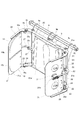
以下、本第1発明の身体支持具の構成について、図4〜図7に基づいてフットレスト4を代表して説明する。図4は、第1実施形態に係る第1位置におけるフットレスト4の斜視図である。図5は、第1実施形態に係る第1位置におけるフットレスト4の平面図である。図6は、第1実施形態に係る第2位置におけるフットレスト4の斜視図である。図7は、第1実施形態に係る第2位置におけるフットレスト4の平面図である。なお、図4〜図7においては、視認性を考慮して載置面21bの図示を省略している。
Hereinafter, the structure of the body support tool of the first invention will be described on behalf of the
フットレスト4は、脚部の背面を支持する略平板状の支持部材20と、支持部材20の左右方向の両端部において前後方向に回動可能に設けられた略平板状の回動部材21と、回動部材21を所望の角度で保持する回動保持手段22と、を有している。支持部材20及び回動部材21には、マッサージ具として、被施療者の脚部を押圧するエアセル9,10が設けられている。このエアセル9,10は、座部2に設けられたエアセル8と同様、給排気装置11からエアが給排気されることによって膨張収縮する。支持部材20における脚部の背面が当接する身体支持面20aに設けられたエアセル9は、左右で対をなしており、外側9aを支点として内側9bが扇状に膨張するよう構成されている。
The
回動部材21について詳述する。回動部材21は、連結部材23を介して上下方向を軸方向とする回動軸24によって支持部材20に枢支されている。そして、回動部材21は、回動部材21が支持部材20と重なってフットレスト4(身体支持具)が略平坦状となる第1位置と、回動部材21が支持部材20に対して略垂直となってフットレスト4(身体支持具)が略凹状となる第2位置と、の2箇所において、後述する回動保持手段22によって位置保持が可能である。
The rotating
第2位置において脚部の側面が当接する回動部材21の施療面21aにはエアセル10が設けられており、このエアセル10は後側10aを支点として前側10bが扇状に膨張するよう構成されている。すなわち、支持部材20に設けられたエアセル9と回動部材21に設けられたエアセル10とにより、脚部を挟持開放することができる。このように回動部材21を第2位置に位置させた姿勢は、脚部にマッサージを行うための使用姿勢である。また、施療面21aの裏側面は被施療者の脚部を載置する載置面21bが形成されている。回動部材21を第1位置に位置させた姿勢は、被施療者の脚部を拘束しない収納姿勢である。
An
回動保持手段22について詳述する。回動保持手段22は、支持部材20の左右両側部に設けられている。具体的には、支持部材20の左右両端部に設けられたブラケット25に上下方向を軸方向とする回動軸26により枢支されたリンク部材27と、回動部材21の内部に設けられたリンク部材27を移動可能に支持するリンク支持部材28と、により構成されている。回動部材21が第2位置に位置するときを例示して説明すると、このリンク部材27は、後端部が支持部材20に枢支され、前端部に上下方向に延びる軸部材29を有している。そして、この軸部材29がリンク支持部材28に設けられた前後方向に長く形成されたガイド溝28aに挿通されている。ガイド溝28aの長手方向両端部には、軸部材29をラッチして回動部材21を第1位置と第2位置の2箇所で位置保持するラッチ部28bが設けられている。この回動保持手段22を構成するリンク部材27及びリンク支持部材28は、回動部材21と一体的に回動するよう構成されている。連結部材23の回動軸24、及びリンク部材27の回動軸26は同一軸心であり、回動部材21の回動支点である。
The rotation holding means 22 will be described in detail. The rotation holding means 22 is provided on both left and right sides of the
このように、回動保持手段22が支持部材20の側部に設けられているため、回動部材21の回動に伴い回動保持手段22が支持部材20の内部に侵入することがなく、フットレスト4の構造を簡素化することができる。また、回動保持手段22が回動部材21と一体的に回動可能であるため、回動保持手段22を背面側から支える部材を別途必要とせず、フットレスト4をコンパクトに作製することができる。
Thus, since the rotation holding means 22 is provided on the side portion of the
更に、支持部材20の左右両端部には、回動部材21が第1位置よりも内側に回動することを防止し、かつ第2位置よりも外側に回動することを規制するストッパー30が設けられている。このストッパー30は、回動軸24の近傍に位置しており、上下方向を軸方向とするピンにより構成されている。連結部材23には切欠部23aが形成されており、切欠部23a内において連結部材23がストッパー30に当接することにより、回動部材21の所定角度以上の回動が規制されている。
Furthermore,
第2位置においてマッサージを受ける場合、身体支持面20aに設けられたエアセル9が膨張し、脚部が回動部材21側(外側)に押動されることにより、回動部材21を外側に移動させる力が作用する。あるいは、施療面21aに設けられたエアセル10が膨張し、脚部を押す反力により回動部材21を外側に移動させる力が作用する。しかし、第1実施形態では、回動部材21の移動範囲を前述した第1位置と第2位置の2箇所に設定しているため、支持部材20と回動部材21の間にストッパー30を設けるだけで、第2位置にある回動部材21が更に外側に移動することを防止でき、簡単な構造で回動部材21を第2位置で保持することができる。
When a massage is received at the second position, the
このマッサージ機1には、回動部材21の位置を検出するセンサ31が設けられている。このセンサ31について詳述する。センサ31は、回動部材21の内部に設けられ、リンク部材27が有する軸部材29の接触/非接触を検出する当接部31aを有するスイッチ等よりなる接触式のセンサにより構成されている。第1実施形態では、当接部31aに軸部材29が接触することにより第2位置が検出される。一方、軸部材29の接触が解除された状態で保持された回動部材21の位置が第1位置となる。
The
図3に示すとおり、前述した昇降機構7c、揉み駆動機構7d、叩き駆動機構7e、及び給排気装置11は、制御手段6に電気的に接続されている。そして、制御手段6からの指示に従ってマッサージ具(マッサージユニット7及びエアセル8〜10)が予め設定されたプログラムにより動作するコース動作や、被施療者が所望する被施療部を選択してマッサージするマニュアル動作を、適宜選択して実行することができる。コース動作及びマニュアル動作の選択は、制御手段6に電気的に接続されたリモコン32を被施療者が操作することにより行うようになっている。動作内容の異なる複数のコース動作が制御手段6に記憶されており、リモコン32に設けられたコース動作ボタン32a〜32cにより好みのコース動作を選択することができる。マニュアル動作については、所望する被施療部をマニュアル動作ボタン32d〜32fにより選択することができる。
As shown in FIG. 3, the elevating
また、センサ31も制御手段6に電気的に接続されている。そして、回動部材21が第1位置であることをセンサ31によって検出されると、制御手段6はフットレスト4のエアセル9,10を非作動状態とするよう給排気装置11を制御する。第1位置において、コース動作が選択された(又はされている)場合は、フットレスト4を除くマッサージ具(マッサージユニット7及び座部2のエアセル8)のみが動作し、マニュアル動作を選択する場合は、脚部に対応するマニュアル動作ボタン32fが選択できないようになる。このように制御することにより、身体支持面20aと第一面21aが略対向状態のときにエアセル9,10が作動することを防止できる。従って、フットレスト4の破損を防止したり、被施療者が望まない回動部材21の移動を防止したりすることができる。
The
[第2実施形態]
以下、本発明の第2実施形態(本第2発明)に係るマッサージ機1の構成について、図8〜図12に基づいて説明する。図8は、第2実施形態に係る第3位置におけるフットレスト40の斜視図である。図9は、第2実施形態に係る第3位置におけるフットレスト40の平面図である。図10は、第2実施形態に係る第2位置におけるフットレスト40の斜視図である。図11は、第2実施形態に係る第2位置におけるフットレスト40の平面図である。図12は、第2実施形態に係る回動保持手段52の平面図であり、(a)は第1位置を示しており、(b)は第2位置を示している。
なお、第1実施形態と共通する構成については、同一符号を付してその説明を省略し、第1実施形態と異なるフットレスト40の構成についてのみ説明する。
[Second Embodiment]
Hereinafter, the structure of the
In addition, about the structure which is common in 1st Embodiment, the same code | symbol is attached | subjected, the description is abbreviate | omitted, and only the structure of the
フットレスト40は、脚部の背面を支持する略平板状の支持部材50と、支持部材50の左右方向の両端部を回動支点50bとして前後方向に回動可能に設けられた略平板状の回動部材51と、回動部材51を所望の角度で保持する回動保持手段52と、を有している。支持部材50及び回動部材51には、マッサージ具として、被施療者の脚部を押圧するエアセル9,10が設けられている。このエアセル9,10は、座部2に設けられたエアセル8と同様、給排気装置11からエアが給排気されることによって膨張収縮する。支持部材50における脚部の背面が当接する身体支持面51aに設けられたエアセル9は、左右で対をなしており、外側9aを支点として内側9bが扇状に膨張するよう構成されている。
The
回動部材51及び回動保持手段52について詳述する。回動保持手段52は、支持部材50と回動部材51の間に設けられたラチェット機構により構成されている。この回動保持手段52は、付勢手段(図示せず)により支点52c回りに常時前方へ付勢されている爪52bを有するとともに、支持部材50側に連結される基部52aと、爪52bに噛合する上下方向を軸方向とする歯車52eを有するとともに、回動部材51側に連結される可動部52dと、により構成されている。そして、この可動部52dは、基部52aに対して回動支点50b回りに前後方向に回動可能である。すなわち、回動部材51は、ラチェット機構である回動保持手段52を介して、支持部材50に対して回動支点50b回りに回動可能に取り付けられている。この歯車52eには、回動部材21が第2位置よりも内側へ回動すること、及び第3位置よりも後側へ回動することを規制する回動規制部52fが設けられている。
The
この回動部材51は、ラチェット機構により構成される回動保持手段52により、回動部材51の施療面51aと支持部材50の身体支持面50aが略面一となり、フットレスト40(身体支持具)が略平坦状となる第3位置と、回動部材51が支持部材50に対して略垂直となってフットレスト40(身体支持具)が略凹状となる第2位置と、において位置保持が可能であるとともに、第2位置と第3位置との間の複数位置で位置保持が可能である。第2位置においては、第1実施形態と同様、支持部材50に設けられたエアセル9と回動部材51に設けられたエアセル10とにより、脚部を挟持開放することができる。このように回動部材51を第2位置に位置させた姿勢は、脚部にマッサージを行うための使用姿勢である。また、回動部材51を第3位置に位置させた姿勢は、被施療者の脚部を拘束しない開放姿勢である。
In this rotating
第2実施形態では、回動部材51の移動範囲を前述した第2位置と第3位置との間に設定しているため、脚部を支持部材50の身体支持面50aから退避させることなく、回動部材51の位置調節を行うことができる。また、回動保持手段52を回動部材51の回動支点50bの近傍に設けたラチェット機構で構成したことにより、回動保持手段52を背面側から支える部材を別途必要とせず、部品点数を削減できる上、フットレスト40をコンパクトに作製することができる。更には、回動部材51を複数位置(角度)に調節することができる。
In the second embodiment, since the movement range of the
[第3実施形態]
以下、本発明の第3実施形態に係るマッサージ機1の構成について、図13に基づいて説明する。図13は、第3実施形態に係るフットレスト70の平面図である。
フットレスト(身体支持具)70は、前述した本第1発明の身体支持具(フットレスト4)と、回動部材21の可動範囲が異なっている。すなわち、フットレスト70は、前述した第2位置(実線)から、回動部材21の施療面21aと支持部材20の身体支持面20aが略面一となる第3位置(二点鎖線)まで、回動部材21が回動可能に構成されている。連結部材23の切欠部230aの範囲を第1実施形態と比べて大きくして、回動部材21を第3位置まで回動可能とするとともに、ラッチ部28bの個数又は配置を変更して、回動部材21を第1位置〜第3位置の各位置で保持可能としている。なお、第1位置及び第3位置においては、回動保持手段22及びストッパー30によって回動部材21の位置が保持されるが、第2位置においては、回動保持手段22のみによって回動部材21の位置が保持されることとなる。
[Third Embodiment]
Hereinafter, the structure of the
The footrest (body support tool) 70 differs from the aforementioned body support tool (footrest 4) of the first invention in the movable range of the rotating
また、本発明のマッサージ機は、図示する形態に限らず、この発明の範囲内において他の形態のものであっても良い。図14は、回動部材21(51)を座部2、背凭れ部3、フットレスト4、及び肘掛け部5に設けたマッサージ機100の斜視図である。
例えば、前述した各実施形態では、回動部材21,51が左右で対をなしている身体支持具4,40を例示したが、回動部材21,51は左右いずれか一方のみであってもよい。
また、図14に示すとおり、身体支持具である座部2、背凭れ部3、及び肘掛け部5についても、前述したフットレスト4(40)と略同一の構成としてもよい。座部2においては、被施療者の臀部又は大腿部の背面が当接する部材が支持部材20(50)であり、支持部材20(50)の左右両端部に設けられた部材が回動部材21(51)である。背凭れ部3においては、被施療者の背中が当接する部材が支持部材20(50)であり、支持部材20(50)の左右両端部に設けられた部材が回動部材21(51)である。肘掛け部5においては、前腕部における手の平に連なる部分が当接する部材が支持部材20(50)であり、左右外端部に設けられた部材が回動部材21(51)である。
Moreover, the massage machine of this invention is not restricted to the form to show in figure, The thing of another form may be sufficient within the scope of this invention. FIG. 14 is a perspective view of the
For example, in each of the above-described embodiments, the body supports 4 and 40 in which the
Further, as shown in FIG. 14, the
簡単な構造で身体支持具の姿勢を変更及び維持することが可能であって、身体支持具を小型化したマッサージ機に適用することができる。 The posture of the body support device can be changed and maintained with a simple structure, and the body support device can be applied to a miniaturized massage machine.
1 マッサージ機
2 座部(身体支持具)
3 背凭れ部(身体支持具)
4 フットレスト(身体支持具)
5 肘掛け部(身体支持具)
6 制御手段
7 マッサージユニット(マッサージ具)
8〜10 エアセル(マッサージ具)
20 支持部材
20a 身体支持面
21 回動部材
21a 施療面
22 回動保持手段
24,26 回動軸(回動支点)
40 フットレスト(身体支持具)
50 支持部材
50a 身体支持面
50b 回動支点
51 回動部材
51a 施療面
52 回動保持手段
70 フットレスト(身体支持具)
1
3 Backrest (body support)
4 Footrest (body support)
5 armrests (body support)
6 Control means 7 Massage unit (massage device)
8-10 Air cell (massage device)
20
40 Footrest (body support)
50
Claims (7)
前記支持部材の身体支持面又は前記回動部材の載置面の裏側面に設けられたマッサージ具と、
前記回動部材を所望の角度に調節して保持する回動保持手段と、を備え、
前記支持部材は、前記回動部材の回動範囲を規制するストッパーを有し、
前記回動保持手段は、前記支持部材の側部に設けられ、前記回動部材と一体的に回動可能であり、
前記回動部材の載置面の裏側面が前記支持部材の身体支持面に重なって前記身体支持具が略平坦となる第1位置と、前記回動部材の載置面の裏側面が前記支持部材の身体支持面に対して略垂直となる第2位置と、の少なくとも2つの位置で前記回動部材を保持可能であることを特徴としたマッサージ機。 A body support comprising: a support member having a body support surface for supporting the body of the user; and a rotation member attached to be rotatable about an end in the left-right direction of the support member as a rotation fulcrum;
A massage tool provided on the body support surface of the support member or the back side surface of the mounting surface of the rotating member;
Rotation holding means for adjusting and holding the rotation member at a desired angle, and
The support member has a stopper that regulates a rotation range of the rotation member;
The rotation holding means is provided on a side portion of the support member, and is rotatable integrally with the rotation member.
A first position in which said body support backside of the mounting face of the rotary member is superimposed over the body-supporting surface of the support member is substantially flat, the back surface is the support of the mounting face of the rotary member A massage machine characterized in that the rotating member can be held at at least two positions: a second position that is substantially perpendicular to the body support surface of the member.
前記支持部材の身体支持面又は前記回動部材の載置面の裏側面に設けられたマッサージ具と、
前記回動部材を所望の角度に調節して保持するための複数のラッチ部を有する回動保持手段と、を備え、
前記回動保持手段は、
前記回動支点の近傍に設けられており、
前記回動部材の載置面の裏側面が前記支持部材の身体支持面に対して略垂直となる第2位置と、前記回動部材の載置面の裏側面が前記支持部材の身体支持面に対して展開して前記身体支持具が略平坦となる第3位置と、の少なくとも2つの位置で前記回動部材を保持可能であることを特徴とするマッサージ機。 A body support comprising: a support member having a body support surface for supporting the body of the user; and a rotation member attached to be rotatable about an end in the left-right direction of the support member as a rotation fulcrum;
A massage tool provided on the body support surface of the support member or the back side surface of the mounting surface of the rotating member;
Rotation holding means having a plurality of latch portions for adjusting and holding the rotation member at a desired angle, and
The rotation holding means is
Provided in the vicinity of the pivot point;
Wherein a second position at which substantially perpendicular to the body-supporting surface of the back surface the support member mounting surface of the rotary member, the body supporting surface of the back surface the support member mounting surface of the rotary member A massage machine characterized in that the rotating member can be held at at least two positions: a third position where the body support tool is substantially flat when unfolded.
The massage machine according to any one of claims 1 to 5 , wherein the rotating members are paired on the left and right sides and can be adjusted and held in an interlocked manner with the left and right.
Priority Applications (2)
| Application Number | Priority Date | Filing Date | Title |
|---|---|---|---|
| JP2012094450A JP5980552B2 (en) | 2012-04-18 | 2012-04-18 | Massage machine |
| CN 201320186767 CN203208316U (en) | 2012-04-18 | 2013-04-15 | Massager |
Applications Claiming Priority (1)
| Application Number | Priority Date | Filing Date | Title |
|---|---|---|---|
| JP2012094450A JP5980552B2 (en) | 2012-04-18 | 2012-04-18 | Massage machine |
Publications (2)
| Publication Number | Publication Date |
|---|---|
| JP2013220238A JP2013220238A (en) | 2013-10-28 |
| JP5980552B2 true JP5980552B2 (en) | 2016-08-31 |
Family
ID=49197894
Family Applications (1)
| Application Number | Title | Priority Date | Filing Date |
|---|---|---|---|
| JP2012094450A Expired - Fee Related JP5980552B2 (en) | 2012-04-18 | 2012-04-18 | Massage machine |
Country Status (2)
| Country | Link |
|---|---|
| JP (1) | JP5980552B2 (en) |
| CN (1) | CN203208316U (en) |
Families Citing this family (2)
| Publication number | Priority date | Publication date | Assignee | Title |
|---|---|---|---|---|
| JP6765403B2 (en) * | 2018-11-08 | 2020-10-07 | 株式会社フジ医療器 | Chair type massage machine |
| CN210872782U (en) * | 2019-05-15 | 2020-06-30 | 蒙发利稻田健康科技(厦门)有限公司 | Dismounting structure of massage machine core |
Family Cites Families (4)
| Publication number | Priority date | Publication date | Assignee | Title |
|---|---|---|---|---|
| JP4228979B2 (en) * | 2004-04-20 | 2009-02-25 | パナソニック電工株式会社 | Massage machine |
| JP2010162071A (en) * | 2009-01-13 | 2010-07-29 | M Tec Co Ltd | Chair type massage machine |
| JP2010167154A (en) * | 2009-01-23 | 2010-08-05 | M Tec Co Ltd | Massage chair |
| JP5441823B2 (en) * | 2010-06-09 | 2014-03-12 | ファミリーイナダ株式会社 | Massage machine |
-
2012
- 2012-04-18 JP JP2012094450A patent/JP5980552B2/en not_active Expired - Fee Related
-
2013
- 2013-04-15 CN CN 201320186767 patent/CN203208316U/en not_active Expired - Fee Related
Also Published As
| Publication number | Publication date |
|---|---|
| CN203208316U (en) | 2013-09-25 |
| JP2013220238A (en) | 2013-10-28 |
Similar Documents
| Publication | Publication Date | Title |
|---|---|---|
| EP2016866B1 (en) | Chair-type massage machine | |
| KR100942113B1 (en) | Footrest device | |
| JP7176083B2 (en) | assistive device | |
| JP6889783B2 (en) | Assistance device | |
| JP2015000070A (en) | Massage machine | |
| EP3598963B1 (en) | Treatment unit and massage machine using treatment unit | |
| JP5733889B2 (en) | Chair type massage machine | |
| JPWO2018179430A1 (en) | Assistance device | |
| KR101359212B1 (en) | Massager | |
| CN114948467B (en) | care device | |
| CN102970957A (en) | chair massager | |
| JP2013220238A (en) | Massage machine | |
| JP6936477B2 (en) | Massage machine | |
| JP5838110B2 (en) | Massage machine | |
| JP2007289445A (en) | Massage machine | |
| JP2014094061A (en) | Massage mechanism | |
| JP2007068983A (en) | Combination bed and reclining chair | |
| JP2010162071A (en) | Chair type massage machine | |
| JP6816259B2 (en) | Assistance device | |
| JP2021007816A (en) | Assistance device | |
| KR20210032304A (en) | Market device | |
| JP2005152597A (en) | Chair | |
| JP2010131248A (en) | Massaging chair equipped with foot massaging device | |
| WO2020070848A1 (en) | Assistance apparatus | |
| JP2016042904A (en) | Multifunctional chair |
Legal Events
| Date | Code | Title | Description |
|---|---|---|---|
| A621 | Written request for application examination |
Free format text: JAPANESE INTERMEDIATE CODE: A621 Effective date: 20150410 |
|
| A131 | Notification of reasons for refusal |
Free format text: JAPANESE INTERMEDIATE CODE: A131 Effective date: 20160122 |
|
| A977 | Report on retrieval |
Free format text: JAPANESE INTERMEDIATE CODE: A971007 Effective date: 20160129 |
|
| A521 | Request for written amendment filed |
Free format text: JAPANESE INTERMEDIATE CODE: A523 Effective date: 20160318 |
|
| TRDD | Decision of grant or rejection written | ||
| A01 | Written decision to grant a patent or to grant a registration (utility model) |
Free format text: JAPANESE INTERMEDIATE CODE: A01 Effective date: 20160628 |
|
| A61 | First payment of annual fees (during grant procedure) |
Free format text: JAPANESE INTERMEDIATE CODE: A61 Effective date: 20160727 |
|
| R150 | Certificate of patent or registration of utility model |
Ref document number: 5980552 Country of ref document: JP Free format text: JAPANESE INTERMEDIATE CODE: R150 |
|
| R250 | Receipt of annual fees |
Free format text: JAPANESE INTERMEDIATE CODE: R250 |
|
| R250 | Receipt of annual fees |
Free format text: JAPANESE INTERMEDIATE CODE: R250 |
|
| R250 | Receipt of annual fees |
Free format text: JAPANESE INTERMEDIATE CODE: R250 |
|
| R250 | Receipt of annual fees |
Free format text: JAPANESE INTERMEDIATE CODE: R250 |
|
| R250 | Receipt of annual fees |
Free format text: JAPANESE INTERMEDIATE CODE: R250 |
|
| R250 | Receipt of annual fees |
Free format text: JAPANESE INTERMEDIATE CODE: R250 |
|
| LAPS | Cancellation because of no payment of annual fees |