JP5979829B2 - Test measurement apparatus and measurement method - Google Patents
Test measurement apparatus and measurement method Download PDFInfo
- Publication number
- JP5979829B2 JP5979829B2 JP2011175800A JP2011175800A JP5979829B2 JP 5979829 B2 JP5979829 B2 JP 5979829B2 JP 2011175800 A JP2011175800 A JP 2011175800A JP 2011175800 A JP2011175800 A JP 2011175800A JP 5979829 B2 JP5979829 B2 JP 5979829B2
- Authority
- JP
- Japan
- Prior art keywords
- trace
- frequency
- measurement
- time domain
- versus time
- Prior art date
- Legal status (The legal status is an assumption and is not a legal conclusion. Google has not performed a legal analysis and makes no representation as to the accuracy of the status listed.)
- Active
Links
Images


Classifications
-
- G—PHYSICS
- G01—MEASURING; TESTING
- G01R—MEASURING ELECTRIC VARIABLES; MEASURING MAGNETIC VARIABLES
- G01R13/00—Arrangements for displaying electric variables or waveforms
- G01R13/02—Arrangements for displaying electric variables or waveforms for displaying measured electric variables in digital form
- G01R13/0218—Circuits therefor
Description
本発明は、被試験信号の測定に関し、特に周波数領域と時間領域の関連する測定結果を一緒に表示できる試験測定装置及び測定方法に関する。 The present invention relates to measurement of a signal under test, and more particularly to a test and measurement apparatus and a measurement method that can display measurement results related to a frequency domain and a time domain together.
無線周波数(Radio Frequency:RF)伝送は、今日のワイヤレスに接続された社会において、急激に普遍的なものとなりつつある。例えば、携帯電話の使用は、世界中で急激に増加しており、高速データ・ネットワークは拡大し、家庭でのワイヤレス通信や、ワイド・エリア・ネットワーク(WAN)が、普通のことになってきた。こうした進展において、試験測定装置が使いやすい機能やインタフェースを提供し、これによって、試験エンジニアや専門技術者のような現場の人間に、何が起こっているか正確に描写できるようにして提供できるようにすることが従来以上に極めて重要となっている。 Radio frequency (RF) transmission is rapidly becoming universal in today's wirelessly connected society. For example, the use of mobile phones is increasing rapidly around the world, high-speed data networks are expanding, and wireless communications at home and wide area networks (WANs) have become commonplace. . In these developments, test and measurement equipment provides easy-to-use functions and interfaces, which can be provided so that people in the field, such as test engineers and specialists, can accurately describe what is happening. This is much more important than ever.
無線周波搬送波(RFキャリア)信号は、搬送波(キャリア)の振幅、周波数又は位相の変化に基づく種々のやり方で情報を伝達できる。政府は、通常、RFレンジを異なる目的で使用するように配分する。結果として、あるデバイスは、所定の帯域内でのみ動作することが許される。こうした制限によって、これら制約に対応しているこれまで以上に複雑ながら効率的で、一般に認められた通信規格に従った方法を採用することとなる。例えば、多くの新しい伝送システムでは、周波数ホッピング及び位相変調を用いて通信規格に対応し、同様なリソースで競合する異なるデバイス間の機能性と互換性を高めている。 A radio frequency carrier (RF carrier) signal can convey information in various ways based on changes in the amplitude, frequency or phase of the carrier. Governments typically allocate the RF range to use for different purposes. As a result, certain devices are allowed to operate only within a predetermined band. These restrictions will lead to more complex, more efficient, and generally accepted methods of communication that address these constraints. For example, many new transmission systems use frequency hopping and phase modulation to support communication standards and improve functionality and compatibility between different devices competing for similar resources.
こうした信号は本質的に複雑なので、従来の技術ではこれら信号を複数の観点から正確に測定することは困難か又は不可能である。リアルタイム・スペクトラム・アナライザ(RTSA)は、周波数領域においてRF信号を測定するのを多くの点で得意としているが、一方で、特に時間領域における特定の測定についての能力が不足している。RTSAでも、復調及びデータ復号能力と、制限はあるものの、ある程度の1チャンネル測定が可能なものもある。しかし、こうした装置では、急速に拡大及び多面化する技術分野において、RF信号をトータルに理解するのに必要な豊富な測定機能は有していない。 Because these signals are inherently complex, it is difficult or impossible with conventional techniques to accurately measure these signals from multiple perspectives. Real-time spectrum analyzers (RTSA) are good at measuring RF signals in the frequency domain in many respects, but on the other hand they lack the ability for specific measurements, especially in the time domain. Even with RTSA, there are some demodulation and data decoding capabilities, and some are capable of measuring one channel to some extent. However, such a device does not have abundant measurement functions necessary for a total understanding of the RF signal in the technical field of rapid expansion and diversification.
RF信号については、ランダムなバースト長、周波数ホッピング・アルゴリズム、位相変調、信号歪み、など要求される特性が多く存在するなか、RF信号の既存の測定方法では、特に時間領域に関して、不十分である。従って、信号伝送における問題を診断したり、完全な信号測定を行ったりすることが困難又は不可能となっている。 For RF signals, there are many required characteristics such as random burst length, frequency hopping algorithm, phase modulation, signal distortion, etc., but existing measurement methods for RF signals are not sufficient, especially in the time domain. . Therefore, it is difficult or impossible to diagnose problems in signal transmission and to perform complete signal measurement.
本発明の実施形態は、無線周波数(RF)信号の時間領域特性を測定するための測定技法を提供する。本発明による装置、システム及び方法は、RF信号を受けてデジタル化及びダウン・コンバートし、デジタル化したRF信号からI(in-phase:同相)及びQ(quadrature:直交)のベースバンド成分情報を生成する。1つ以上のIQベース時間領域トレースが、I及びQベースバンド成分情報を用いて生成される。IQベース時間領域トレースには、例えば、周波数対時間トレース、位相対時間トレース、振幅(つまり、電力対時間トレース)、I対時間トレース、そして、Q対時間トレースが含まれる。 Embodiments of the present invention provide measurement techniques for measuring time domain characteristics of radio frequency (RF) signals. The apparatus, system, and method according to the present invention receive and digitize and down-convert an RF signal, and obtain I (in-phase) and Q (quadrature) baseband component information from the digitized RF signal. Generate. One or more IQ base time domain traces are generated using the I and Q baseband component information. IQ-based time domain traces include, for example, frequency versus time trace, phase versus time trace, amplitude (ie, power versus time trace), I versus time trace, and Q versus time trace.
実施形態によっては、試験測定装置の測定部は、時間領域波形に基づいて生成できる種々の適切な測定結果の中から、IQベース時間領域トレースの周波数、IQベース時間領域トレースのパルス幅、IQベース時間領域トレースと他の信号間の遅延時間、そしてIQベース時間領域トレースの立ち上がり及び立ち下がり時間のようなIQベース時間領域トレースの特性に対応する複数の測定値を生成する。例えば、測定部は、周波数対時間トレース中の周波数ホップの周波数を測定し、試験測定装置の表示ユニット上でその測定値を表示するか、さもなくば、測定値を外部のコンピュータ又は記憶装置に伝送する。一般に、信号特性に対応する測定結果は、時間領域レコード全体に渡って生成されるか、さもなくば、取り込んだレコードの最初の部分又はレコード中の複数の場所で生成される。複数の測定は、一度に行われるか、組合せて行われる。以下で詳しく説明するように、種々の測定値をIQベース時間領域トレースに適用できる。 In some embodiments, the measurement unit of the test and measurement apparatus may select an IQ-based time-domain trace frequency, an IQ-based time-domain trace pulse width, an IQ-based value from various suitable measurement results that can be generated based on the time-domain waveform. A plurality of measurements are generated corresponding to characteristics of the IQ base time domain trace, such as the delay time between the time domain trace and other signals, and the rise and fall times of the IQ base time domain trace. For example, the measurement unit measures the frequency of the frequency hop in the time trace and displays the measurement value on the display unit of the test measurement device, or the measurement value is stored in an external computer or storage device. To transmit. In general, the measurement results corresponding to the signal characteristics are generated over the entire time domain record or else at the first part of the acquired record or at multiple locations in the record. Multiple measurements are made at once or in combination. As described in detail below, various measurements can be applied to the IQ base time domain trace.
本願の第1観点の発明は、試験測定装置であって、被試験電気信号を受ける入力端子と、上記被試験電気信号をデジタル化するアナログ・デジタル・コンバータと、デジタル化した上記被試験電気信号からI(同相)及びQ(直交)ベースバンド成分情報を生成するデジタル・ダウン・コンバータと、上記I及びQベースバンド成分情報を用いて1つ以上のIQベース時間領域トレースを生成するトレース生成部と、1つ以上の上記IQベース時間領域トレースの特性に対応する1つ以上の測定値を生成する測定部とを具えている。 The first aspect of the present invention is a test and measurement apparatus, which is an input terminal for receiving an electric signal under test, an analog / digital converter for digitizing the electric signal under test, and the digitized electric signal under test A digital down converter that generates I (in-phase) and Q (quadrature) baseband component information from the signal, and a trace generation unit that generates one or more IQ base time domain traces using the I and Q baseband component information And a measurement unit that generates one or more measurements corresponding to the characteristics of the one or more IQ-based time domain traces.
本願の第2観点の発明は、第1観点の試験測定装置において、1つ以上の上記IQベース時間領域トレースが周波数対時間トレースを含み、上記測定部は上記周波数対時間トレース中の周波数ホップの周波数を測定するように構成され、これによって、上記被試験信号の1側面として、周波数変調ホップ・レートを決定するものである。 According to a second aspect of the present invention, in the test and measurement apparatus according to the first aspect, the one or more IQ-based time domain traces include a frequency vs. time trace, and the measurement unit includes a frequency hop in the frequency vs. time trace. It is configured to measure frequency, thereby determining the frequency modulation hop rate as one aspect of the signal under test.
本願の第3観点の発明は、第1観点の試験測定装置において、1つ以上の上記IQベース時間領域トレースが周波数対時間トレースを含み、上記測定部は上記周波数対時間トレースのパルス幅を測定するように構成され、これによって、上記被試験信号の1側面として、周波数変調ホップ持続時間を決定するものである。 According to a third aspect of the present invention, in the test and measurement apparatus according to the first aspect, one or more of the IQ base time domain traces include a frequency versus time trace, and the measurement unit measures a pulse width of the frequency versus time trace. Thus, the frequency modulation hop duration is determined as one aspect of the signal under test.
本願の第4観点の発明は、第1観点の試験測定装置において、上記入力端子が第1入力端子から構成され、上記試験測定装置が更に第2信号を受ける第2入力端子を具えているものである。 According to a fourth aspect of the present invention, in the test and measurement apparatus according to the first aspect, the input terminal includes a first input terminal, and the test and measurement apparatus further includes a second input terminal for receiving a second signal. It is.
本願の第5観点の発明は、第4観点の試験測定装置において、1つ以上の上記IQベース時間領域トレースが周波数対時間トレースを含み、上記測定部は上記第2信号と上記周波数対時間トレース間の遅延時間を測定するように構成されているものである。 According to a fifth aspect of the present invention, in the test and measurement apparatus according to the fourth aspect, the one or more IQ-based time domain traces include a frequency versus time trace, and the measurement unit includes the second signal and the frequency versus time trace. It is configured to measure the delay time between.
本願の第6観点の発明は、第1観点の試験測定装置において、1つ以上の上記IQベース時間領域トレースが位相対時間トレースを含み、上記測定部は上記位相対時間トレースの特性に対応する1つ以上の測定値を生成するように構成されているものである。 According to a sixth aspect of the present invention, in the test and measurement apparatus according to the first aspect, one or more of the IQ base time domain traces include a phase versus time trace, and the measurement unit corresponds to the characteristics of the phase versus time trace. It is configured to generate one or more measurements.
本願の第7観点の発明は、第1観点の試験測定装置において、1つ以上の上記IQベース時間領域トレースが電力対時間トレースを含み、上記測定部が上記電力対時間トレースの特性に対応する1つ以上の測定値を生成するように構成されているものである。 According to a seventh aspect of the present invention, in the test and measurement apparatus according to the first aspect, one or more of the IQ base time domain traces include a power versus time trace, and the measurement unit corresponds to the characteristics of the power versus time trace. It is configured to generate one or more measurements.
本願の第8観点の発明は、第1観点の試験測定装置において、上記測定値を受けて表示する表示ユニットを更に具えるものである。 The invention of the eighth aspect of the present application further includes a display unit that receives and displays the measurement value in the test measurement apparatus of the first aspect.
本願の第9観点の発明は、第1観点の試験測定装置において、コントローラが上記トレース生成部及び上記測定部を含み、上記コントローラは1つ以上の上記測定値を外部デバイスに伝送するように構成されることを特徴としている。 A ninth aspect of the present invention is the test and measurement apparatus according to the first aspect, wherein the controller includes the trace generation unit and the measurement unit, and the controller transmits one or more measurement values to an external device. It is characterized by being.
本願の第10観点の発明は、試験測定装置において、時間領域トレースを測定するための方法であって、
上記試験測定装置の端子において被試験電気信号を受けるステップと、
アナログ・デジタル・コンバータを用いて上記被試験電気信号をデジタル化するステップと、
デジタル化した上記被試験電気信号をダウン・コンバートしてI(同相)及びQ(直交)ベースバンド成分情報を生成するステップと、
上記I及びQベースバンド成分情報を用いて1つ以上のIQベース時間領域トレースを生成するステップと、
1つ以上の上記IQベース時間領域トレースの複数の測定値を自動的に生成するステップとを具えている。
The invention of the tenth aspect of the present application is a method for measuring a time-domain trace in a test and measurement apparatus,
Receiving an electrical signal under test at a terminal of the test and measurement device;
Digitizing the electrical signal under test using an analog to digital converter;
Down-converting the digitized electrical signal under test to generate I (in-phase) and Q (quadrature) baseband component information;
Generating one or more IQ base time domain traces using the I and Q baseband component information;
Automatically generating a plurality of measurements of one or more of the IQ-based time domain traces.
本願の第11観点の発明は、第10観点の方法において、1つ以上の上記IQベース時間領域トレースの複数の上記測定値を表示ユニット上に表示するステップを更に具えている。 The invention of the eleventh aspect of the present application further includes the step of displaying a plurality of the measured values of one or more of the IQ base time domain traces on a display unit in the method of the tenth aspect.
本願の第12観点の発明は、第10観点の方法において、複数の上記測定値を外部デバイスに伝送するステップを更に具えている。 The invention of the twelfth aspect of the present application further includes the step of transmitting the plurality of measured values to an external device in the method of the tenth aspect.
本願の第13観点の発明は、第10観点の方法において、1つ以上の上記IQベース時間領域トレースを生成するステップが、周波数対時間トレースを生成するステップを含んでいることを特徴としている。 The invention of the thirteenth aspect of the present application is characterized in that, in the method of the tenth aspect, the step of generating one or more of the IQ-based time domain traces includes the step of generating a frequency versus time trace.
本願の第14観点の発明は、第13観点の方法において、1つ以上の上記IQベース時間領域トレースの複数の上記測定値を自動的に生成するステップが、
上記周波数対時間トレース中の周波数ホップの周波数を測定することによって、周波数変調ホップ・レートを決定するステップと、
上記周波数変調ホップ・レートに対応する測定値を表示ユニット上に表示するステップとを含んでいることを特徴としている。
According to a fourteenth aspect of the present invention, in the method of the thirteenth aspect, the step of automatically generating a plurality of the measurement values of the one or more IQ-based time domain traces comprises:
Determining a frequency modulation hop rate by measuring the frequency of frequency hops in the frequency versus time trace;
Displaying a measurement value corresponding to the frequency modulation hop rate on a display unit.
本願の第15観点の発明は、第13観点の方法において、1つ以上の上記IQベース時間領域トレースの複数の上記測定値を自動的に生成するステップが、
上記周波数対時間トレースのパルス幅を測定することによって、周波数変調ホップ持続時間を決定するステップと、
上記周波数変調ホップ持続時間に対応する測定値を表示ユニット上に表示するステップとを更に含んでいることを特徴としている。
According to a fifteenth aspect of the present invention, in the method of the thirteenth aspect, the step of automatically generating a plurality of the measured values of one or more of the IQ-based time domain traces includes:
Determining the frequency modulation hop duration by measuring the pulse width of the frequency versus time trace;
Displaying the measurement corresponding to the frequency modulation hop duration on a display unit.
本願の第16観点の発明は、第10観点の方法において、上記端子が第1端子から構成されると共に、上記試験測定装置の第2端子において第2信号を受けるステップを更に具えていることを特徴としている。 The invention of the sixteenth aspect of the present application is the method of the tenth aspect, further comprising the step of receiving the second signal at the second terminal of the test and measurement apparatus, while the terminal is constituted by the first terminal. It is a feature.
本願の第17観点の発明は、第16観点の方法において、
1つ以上の上記IQベース時間領域トレースを生成するステップが、周波数対時間トレースを生成するステップを含み、
複数の上記測定値を自動的に生成するステップが、上記第2信号と上記周波数対時間トレース間の遅延時間を測定するステップと、表示ユニットに遅延時間測定結果を表示するステップとを有することを特徴としている。
The invention of the seventeenth aspect of the present application is the method of the sixteenth aspect,
Generating one or more of the IQ-based time domain traces includes generating a frequency versus time trace;
Automatically generating a plurality of the measured values comprises measuring a delay time between the second signal and the frequency versus time trace, and displaying a delay time measurement result on a display unit. It is a feature.
本願の第18観点の発明は、第10観点の方法において、
1つ以上の上記IQベース時間領域トレースを生成するステップが、位相対時間トレースを生成するステップを含み、
複数の上記測定値を自動的に生成するステップが、上記位相対時間トレースの特性に対応する複数の測定値を生成するステップを含んでいることを特徴としている。
The invention of the eighteenth aspect of the present application is the method of the tenth aspect,
Generating one or more of the IQ-based time domain traces includes generating a phase versus time trace;
The step of automatically generating the plurality of measurement values includes the step of generating a plurality of measurement values corresponding to the characteristics of the phase versus time trace.
本願の第19観点の発明は、第10観点の方法において、
1つ以上の上記IQベース時間領域トレースを生成するステップが、電力対時間トレースを生成するステップを含み、
複数の上記測定値を自動的に生成するステップが、上記電力対時間トレースの特性に対応する複数の測定値を生成するステップを含んでいることを特徴としている。
According to a nineteenth aspect of the present invention, in the method of the tenth aspect,
Generating one or more of the IQ-based time domain traces includes generating a power versus time trace;
The step of automatically generating the plurality of measurement values includes the step of generating a plurality of measurement values corresponding to the characteristics of the power versus time trace.
本願の第20観点の発明は、磁気ディスク、光学ディスク、固体ディスク、揮発性メモリ、不揮発性メモリ、ランダム・アクセス・メモリ、リード・オンリ・メモリ又はフラッシュ・メモリを含む機器から情報を引き出す装置であって、試験測定装置で実行したときに、第10観点の発明のステップを機械に実行させる結果となる関連する命令を有する機械アクセス可能なメディアを具えている。 The invention of the twentieth aspect of the present application is an apparatus for extracting information from a device including a magnetic disk, an optical disk, a solid disk, a volatile memory, a nonvolatile memory, a random access memory, a read only memory, or a flash memory. A machine accessible medium having associated instructions that, when executed on a test and measurement device, causes the machine to perform the steps of the tenth aspect of the invention.
本発明の目的、効果及び他の新規な点は、以下の詳細な説明を添付の特許請求の範囲及び図面とともに読むことによって明らかとなろう。 The objects, advantages and other novel features of the present invention will become apparent from the following detailed description when read in conjunction with the appended claims and drawings.
図1は、アナログ・デジタル・コンバータ(ADC)108、デジタル・ダウン・コンバータ115、トレース生成部145及び測定部147を含むコントローラ140、表示ユニット150を有する本発明の実施形態例による試験測定装置100のブロック図である。試験測定装置100は、デジタル・オシロスコープ、リアルタイム・スペクトラム・アナライザ(RTSA)、その他の適切な測定装置としても良い。簡潔かつ一貫性を持たせるため、ここでは、全般に試験測定装置としてオシロスコープを例に説明するが、これに限られるものではない。
FIG. 1 shows a test and
オシロスコープ100は、ここで説明する種々の実施形態での利用に適した入力端子110のような入力端子又はチャンネルを複数有している。このオシロスコープは、入力端子110を1つだけ持つとしても良いが、本願発明は、4つ又は任意の数の入力を有するオシロスコープにも等しく適用可能である。オシロスコープ100の構成要素は、互いに直接結合された形で示されているが、オシロスコープ100は、必ずしも図示しないものの、他の種々の回路、ソフトウェア要素、入力端子、出力端子、インタフェースを含んでも良く、これらは図示したオシロスコープ100の構成要素の間等に配置される。
The
入力端子110は、被試験電気信号、好ましくはRF信号を受ける。このRF信号は、アナログ中間周波数(IF)信号に変換しても良く、これはADC108でデジタル化される前にフィルタされる。しかし、基準となるのは、ここでは1つ又は複数のRF信号であり、これには1つ以上のRF信号、又は、RF信号から導かれた1つ以上のIF信号が含まれると考えて良い。
Input terminal 110 receives an electrical signal under test, preferably an RF signal. This RF signal may be converted to an analog intermediate frequency (IF) signal, which is filtered before being digitized by the
ADC108は、被試験RF信号をデジタル化するように構成される。デジタル・ダウン・コンバータ115は、ADC108と動作可能に結合され、デジタル化されたRF信号を受けて、このデジタルRF信号からI(同相)及びQ(直交)ベースバンド成分のデータ又は信号を生成する。より具体的には、ミキサ120が数値的にサイン及びコサインをデジタルRF信号にかけ算し、これによってI及びQ成分情報を生成する。この情報には、オリジナルのRF信号中に存在する情報の全てが含まれる。信号成分データは、その後、間引きフィルタ125を用いて間引きされる。これは、信号に関するサンプル数とノイズをデジタル的にフィルタして減少させる。
The
取込み(アクイジション)メモリ130は、デジタル・ダウン・コンバータ115と動作可能に結合されて、RF信号に関するデジタルI及びQベースバンド成分情報の1つ以上のレコード135を取込み及び蓄積する。言い換えると、取込みメモリ130は、デジタル・ダウン・コンバータ115からI及びQベースバンド成分情報を受けて、これを蓄積することができる。実施形態によっては、ADC108が出力するデジタル・データを、メモリ130のようなメモリに最初に直接蓄積しても良く、その後、ダウン・コンバータ115がアクセスしてI及びQベースバンド成分情報を生成するようにしても良い。オシロスコープの各入力端子110は、成分情報が蓄積された取込みメモリ130の異なる部分又は異なるレコード135と関係がある。取込みメモリ130は、種々のメモリとしても良い。例えば、取込みメモリ130は、揮発性メモリ、非揮発性メモリ、ダイナミック・ランダム・アクセス・メモリ(DRAM)、スタティック・メモリ(SRAM)などとしても良い。
An acquisition memory 130 is operatively coupled to the digital down converter 115 to capture and store one or more records 135 of digital I and Q baseband component information about the RF signal. In other words, the acquisition memory 130 can receive and store I and Q baseband component information from the digital down converter 115. In some embodiments, the digital data output by the
コントローラ140は、取込みメモリ130と動作可能に結合されており、I及びQ成分情報を受ける。コントローラ140は、表示ユニット150にも結合され、被試験信号を処理し、表示ユニット150に表示する対応する波形、トレース、又は測定結果を生成する。トレース及び測定結果を表示する代わりに、又は、これらに加えて、コントローラ140は、バスやワイヤなどの伝送線を介してこれらを外部デバイス160に伝送することもできる。外部デバイス160は、例えば、試験測定装置とは別個のコンピュータや、外部記憶装置などとしても良い。
Controller 140 is operatively coupled to acquisition memory 130 and receives I and Q component information. The controller 140 is also coupled to the
コントローラ140は、トレース生成部145及び測定部147を有していても良い。トレース生成部145は、I及びQベースバンド成分情報を用いて、1つ以上のIQベースの時間領域トレースを生成する。例えば、ダウン・コンバートした後、トレース生成部145は、QをIで割ったもののアークタンジェント(つまり、ARCTAN(Q/I))の計算によって位相を生成しても良い。トレース生成部145は、位相の微分(導関数)を計算する(つまり、d/dt(phase))ことによって、周波数を生成しても良い。位相及び周波数は、位相対時間トレース、周波数対時間トレースをそれぞれプロットするのに用いられる。加えて、トレース生成部145は、振幅(つまり、電力対時間)トレースを生成しても良く、これは、例えば、Iの2乗にQの2乗を加えたものの平方根を取る(例えば、SQRT(I^2+Q^2))ことで生成しても良い。種々のトレースについて、以下で更に詳細に説明する。 The controller 140 may include a trace generation unit 145 and a measurement unit 147. The trace generation unit 145 generates one or more IQ-based time domain traces using the I and Q baseband component information. For example, after down-conversion, the trace generation unit 145 may generate a phase by calculating an arc tangent of Q divided by I (that is, Arctan (Q / I)). The trace generation unit 145 may generate a frequency by calculating a differential (derivative) of the phase (that is, d / dt (phase)). Phase and frequency are used to plot phase versus time trace and frequency versus time trace, respectively. In addition, the trace generator 145 may generate an amplitude (ie, power versus time) trace, which takes, for example, the square root of I squared plus Q squared (eg, SQRT (I ^ 2 + Q ^ 2)). Various traces are described in more detail below.
測定部147は、IQベースの時間領域トレースの測定可能な観点の少なくとも1つから測定値を生成する。例えば、IQベース時間領域トレースが周波数対時間トレースなら、測定部147は、周波数対時間トレース中の周波数がホップする周波数を測定することによって、その測定値を生成し、これによって、その信号の1つの側面である周波数変調ホップ・レートを決定する。他の例としては、測定部147は、周波数対時間トレースのパルス幅を測定し、これによって、信号の1つの側面である周波数変調ホップ持続時間(duration)を決定する。一般に、測定結果は信号特性に対応し、時間領域レコード全体に渡って生成されるか、さもなくば、取込みメモリ130のレコード135のような取込みレコードの最初の部分か、又は、取込みレコード中の複数の場所において生成される。測定は、1度に1つか、組合せて行われても良い。以下で更に説明する他の測定値は、周波数対時間トレースに関しても生成される。実際には、当業者に周知の他の適切な種々の測定をIQベース時間領域トレースに適用しても良い。 The measurement unit 147 generates a measurement value from at least one of the measurable aspects of the IQ-based time domain trace. For example, if the IQ-based time domain trace is a frequency versus time trace, the measurement unit 147 generates the measurement value by measuring the frequency at which the frequency in the frequency trace is hopped, thereby obtaining one of the signals. Determine the frequency modulation hop rate, which is one aspect. As another example, the measurement unit 147 measures the pulse width of the frequency versus time trace, thereby determining the frequency modulation hop duration, which is one aspect of the signal. In general, the measurement results correspond to signal characteristics and are generated over the entire time domain record, or else the first part of the acquisition record, such as record 135 of acquisition memory 130, or in the acquisition record Generated at multiple locations. Measurements may be made one at a time or in combination. Other measurements, described further below, are also generated for frequency versus time traces. In practice, various other suitable measurements known to those skilled in the art may be applied to the IQ-based time domain trace.
加えて、測定部147は、I及びQベースバンド成分情報の複数のトレースそれぞれの測定可能な観点の少なくとも1つから測定値を生成できる。言い換えると、Iベースバンド成分情報のトレース又はQベースバンド成分情報のトレースに対して、測定を直接行っても良い。 In addition, the measurement unit 147 can generate a measurement value from at least one of the measurable viewpoints of each of the plurality of traces of the I and Q baseband component information. In other words, the measurement may be performed directly on the trace of the I baseband component information or the trace of the Q baseband component information.
表示ユニット150は、RF信号のスペクトラムやRF信号のスペクトログラムのような周波数領域トレースと共に、1つ以上のIQベース時間領域トレースを表示ユニットの同じウィンドウ内に一緒に(つまり、互いに近くに、又は、重ねて)表示するのに適したものとなっている。RF信号のスペクトラムやスペクトログラムのような周波数領域トレースは、高速フーリエ変換(FFT)アルゴリズムをI及びQデータに適用することによって生成される。複数のIQベース時間領域トレースの測定値が生成されると、これら測定値も、表示ユニットの同じウィンドウ内のオシロスコープのユーザが見やすい場所に表示される。言い換えると、IQベース時間領域トレース、IQベース周波数領域トレース及び測定値は、1つのウィンドウ内において、互いに近い位置に、表示ユニット150のおおよそ全表示領域を占めるように表示できる。
The
ここで、周波数領域に言及すると、これは、当業者には理解されるように、周波数領域の測定やトレースを指すものと考えるべきである。例えば、RF信号のスペクトラムは、周波数領域であって、周波数レンジを表す水平軸と、任意の周波数についての振幅又は信号電力を表す垂直軸とを有するプロットを含んでいる。加えて、RF信号のスペクトログラムは、周波数領域に含まれると考えられ、典型的には、周波数レンジを表す水平軸と、時間を表す垂直軸とを有し、色を変化させることでトレースの振幅を表すプロットを有している。 Reference to the frequency domain here should be considered to refer to frequency domain measurements and traces, as will be understood by those skilled in the art. For example, the spectrum of an RF signal is in the frequency domain and includes a plot with a horizontal axis representing the frequency range and a vertical axis representing the amplitude or signal power for any frequency. In addition, the spectrogram of the RF signal is considered to be included in the frequency domain, typically having a horizontal axis representing the frequency range and a vertical axis representing time, and changing the color to change the amplitude of the trace. Has a plot.
一方、時間領域は、複数の異なる形式の測定やトレースを含んでいる。例えば、周波数対時間の測定やトレースは、周波数領域というよりは、時間領域に属すると考えられ、また、これは時間を表す水平軸と、周波数を表す垂直軸とを有すると考えられる。周波数対時間測定は、時間領域に関して、スペクトログラムよりも高い解像度を有している。 On the other hand, the time domain includes a number of different types of measurements and traces. For example, frequency versus time measurements or traces are considered to belong to the time domain rather than the frequency domain, and this is considered to have a horizontal axis representing time and a vertical axis representing frequency. Frequency versus time measurements have a higher resolution than the spectrogram in the time domain.
周波数対時間と同様に、電力対時間トレースは、時間に対して信号電力がどのように変化するかを示し、時間領域に属すると考えられ、その水平軸は時間を表し、垂直軸は電力(線形なスケールの電圧の代わりに、典型的には、対数(log)スケール)を表す。加えて、位相対時間の測定やトレースは、時間の関数として表示され、時間領域に属すると考えられる。その水平軸は時間を表し、垂直軸は位相値のレンジを表す。ここでIQベース時間領域トレースに言及すると、これはI及びQ成分情報又はデータから得られた信号又はトレースを指しており、周波数領域とは対照的に、時間領域に属している。 Similar to frequency versus time, the power versus time trace shows how the signal power varies with time and is considered to belong to the time domain, with its horizontal axis representing time and the vertical axis representing power ( Instead of a linear scale voltage, it typically represents a log scale). In addition, phase versus time measurements and traces are displayed as a function of time and are considered to belong to the time domain. The horizontal axis represents time and the vertical axis represents the range of phase values. Referring now to an IQ-based time domain trace, this refers to a signal or trace derived from I and Q component information or data and belongs to the time domain as opposed to the frequency domain.
ADC108、デジタル・ダウン・コンバータ115、トレース生成部及び測定部を含むコントローラ140並びに表示ユニット150のいずれもが、ハードウェア、ソフトウェア、ファームウェア、又はこれらの組合せたものの中に存在するか、または、これらを用いて実現される。
Any of controller 140 including
図2A及び2Bは、本発明の実施形態の例によるもので、種々の受信信号又はこれから得られた信号や、周波数対時間トレース225のようなトレースを含む簡略化した表示画面200を示している。
2A and 2B illustrate a
図2Aに示すように、表示画面200の上部には、制御信号220と周波数対時間トレース225がある。表示画面200の上部に示しているものの、信号やトレースは、表示領域のどこに配置しても良い。加えて、信号220は「制御」信号としているが、実施形態によっては、この信号は、試験測定装置が受信又は生成した時間領域信号のような任意の信号としても良い。オシロスコープの複数の端子110は、RF信号や制御信号220のような種々の信号を同時に受信するのに利用でき、周波数対時間トレース225のようなトレースは、受信信号に関する情報から求めることができる。
As shown in FIG. 2A, at the top of the
実施形態によっては、制御信号220は、周波数の遷移を示すものでも良く、周波数対時間トレース225に、この遷移が反映される。実施形態によっては、信号とトレース間で関係や影響を生じさせないようにする必要のあるものもある。例えば、時間領域信号(つまり、制御信号220と関係のない信号)と周波数対時間トレース225の間で測定を行っても良い。
In some embodiments, the
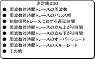
図1の測定部147は、周波数対時間トレースに関する1つ以上の測定値230を生成できる。例えば、測定部147は、周波数対時間トレース中の周波数ホップの周波数測定値を生成でき、表示画面200上にその測定値が表示される。測定部147は、図2Bに例として示すように、周波数対時間トレースのパルスのパルス幅、制御信号及び周波数対時間トレース間の遅延時間、周波数対時間トレースのパルス又は一部分の立ち上がり時間、周波数対時間トレースのパルス又は一部分の立ち下がり時間、周波数対時間トレースのオーバーシュート状態、周波数対時間トレースのスルーレート、などのその他の種々の測定値230を生成できる。実際的には、当業者には周知のように、その他の種々の適切な測定を周波数対時間トレースに適用できる。加えて、コントローラ140は、バスやワイヤなどの伝送線を介して測定値230を外部デバイス160に伝送することもできる。
The measurement unit 147 of FIG. 1 can generate one or more measurement values 230 for a frequency versus time trace. For example, the measurement unit 147 can generate a frequency measurement value of a frequency hop in the frequency versus time trace, and the measurement value is displayed on the
更には、時間領域の周波数対時間トレースや、制御信号、測定値と共に、周波数領域のスペクトログラム285やスペクトラム290を一緒に(つまり、互いに近く又は重ねて)、表示ユニット150の表示画面200のほぼ全体を占めるように1つのウィンドウ200中に表示できる。言い換えると、スペクトログラム285やスペクトラム290は、他の信号やトレースと別個の表示画面には表示されないのであって、そうでないと、信号間の情報を相互に関連させるのが困難になる。むしろ、周波数領域のスペクトログラム285やスペクトラム290からの情報は、同じ表示画面内の周波数対時間トレース225や測定値230のような時間領域トレースからの情報と相互に関連が取れるようにしている。
In addition, the frequency domain spectrogram 285 and spectrum 290 together with the time domain frequency vs. time trace, control signals, and measurements (ie, close to each other or superimposed on each other) can be used to provide substantially the
実施形態によっては、測定部147は、ユーザの選択に応じて周波数対時間トレースの複数の測定値を生成し、ユーザが更に分析できるように、表示画面200上に自動的に測定値230を表示させる。例えば、ユーザの入力に応じて、周波数対時間トレース中の周波数ホップの周波数と、周波数対時間トレースのパルス幅とを自動的に測定することによって、周波数変調ホップ・レート及びホップ持続時間が自動的に決定され、測定値が表示されるので、ユーザは測定値を観測できる。制御信号に関する遅延時間のようなその他の測定結果も、自動的に決定されて表示できる。上述した測定技法や測定値は、オシロスコープ100によって自動的に実行及び測定され、表示されることが理解されるであろう。
In some embodiments, the measurement unit 147 generates a plurality of frequency vs. time trace measurements in response to a user selection and automatically displays the measurement values 230 on the
図3は、本発明の実施形態の例による種々の受信信号又は得られた信号や、位相対時間トレース325のようなトレースを含む簡略化した表示画面300を示す。
FIG. 3 shows a
図3に示すように、表示画面300の上部には、制御信号320と位相対時間トレース325がある。表示画面300の上部に示しているものの、信号やトレースは、表示領域のどこに配置しても良い。加えて、信号320は「制御」信号としているが、実施形態によっては、この信号は、試験測定装置が受信又は生成した時間領域信号のような任意の信号としても良い。オシロスコープの複数の端子110は、RF信号や制御信号320のような種々の信号を同時に受信するのに利用でき、位相対時間トレース325のようなトレースは、受信信号に関する情報から求めることができる。
As shown in FIG. 3, at the top of the
実施形態によっては、制御信号320は、RF信号の位相遷移又はその他の特性を示すとしても良い。実施形態によっては、信号とトレース間で関係や影響を生じさせないようにする必要のあるものもある。例えば、時間領域信号(つまり、制御信号320と関係のない信号)と位相対時間トレース325の間で測定を行っても良い。
In some embodiments, the
図1の測定部147は、位相対時間トレースに関する1つ以上の測定値330を生成できる。例えば、測定部147は、上述した測定値230と類似するか、これらに対応する測定値330を生成できるが、これらは位相対時間トレース325に測定を適用したものである。測定値330は、表示画面300上に表示するか、バスやワイヤなどの伝送線を介して外部デバイス160に伝送できる。実際的には、当業者には周知のように、その他の種々の適切な測定を位相対時間トレースに適用できる。
The measurement unit 147 of FIG. 1 can generate one or more measurements 330 for the phase versus time trace. For example, the measurement unit 147 can generate measurement values 330 that are similar to or correspond to the measurement values 230 described above, which are measurements applied to the phase versus time trace 325. The measured value 330 can be displayed on the
更には、時間領域の位相対時間トレース325や、制御信号320、測定値330と共に、周波数領域のスペクトログラム385やスペクトラム390を一緒に(つまり、互いに近く又は重ねて)、表示ユニット150の表示画面300のほぼ全体を占めるように1つのウィンドウ300中に表示できる。言い換えると、スペクトログラム385やスペクトラム390は、他の信号やトレースと別個の表示画面には表示されないのであって、そうでないと、信号間の情報を相互に関連させるのが困難になる。むしろ、周波数領域のスペクトログラム385やスペクトラム390からの情報は、同じ表示画面内の位相対時間トレース325や測定値330のような時間領域トレースからの情報と相互に関連が取れるようにしている。
In addition, the frequency domain spectrogram 385 and spectrum 390, together with the time domain phase versus time trace 325,
実施形態によっては、測定部147は、ユーザの選択に応じて自動的に位相対時間トレースの複数の測定値を生成し、ユーザが更に分析できるように、表示画面300上に自動的に測定値330を表示させる。例えば、制御信号320と位相対時間トレース325間の遅延時間を測定することによって、制御信号と回路の位相変調出力信号間の遅延時間が決定される。これら測定結果は、自動的に測定されて表示される。上述した測定技法や測定値のいずれもが、位相対時間トレースの特性を測定するために利用でき、オシロスコープ100によって自動的に測定され、表示されることが理解されるであろう。
In some embodiments, the measurement unit 147 automatically generates a plurality of phase versus time trace measurements in response to a user's selection and automatically displays the measurement values on the
図4は、本発明の実施形態の例によるもので、種々の受信信号又はこれから得られた信号や、電力対時間トレース425のようなトレースを含む簡略化した表示画面400を示している。
FIG. 4 illustrates a
図4に示すように、表示画面400の上部には、制御信号420と振幅(つまり、電力対時間)トレース425がある。表示画面400の上部に示しているものの、信号やトレースは、表示領域のどこに配置しても良い。加えて、信号420は「制御」信号としているが、実施形態によっては、この信号は、試験測定装置が受信又は生成した時間領域信号のような任意の信号としても良い。オシロスコープの複数の端子110は、RF信号や制御信号420のような種々の信号を同時に受信するのに利用でき、電力対時間トレース425のようなトレースは、受信信号に関する情報から求めることができる。
As shown in FIG. 4, at the top of the
実施形態によっては、制御信号420は、RF信号の電力又は他の特性の遷移を示すものでも良い。実施形態によっては、信号とトレース間で関係や影響を生じさせないようにする必要のあるものもある。例えば、時間領域信号(つまり、制御信号420と関係のない信号)と電力対時間トレース425の間で測定を行っても良い。
In some embodiments, the
図1の測定部147は、電力対時間トレースに関する1つ以上の測定値430を生成できる。例えば、測定部147は、上述した測定値230と類似するか、これらに対応する測定値430を生成できるが、これらは電力対時間トレース425に測定を適用したものである。測定値430は、表示画面400上に表示するか、バスやワイヤなどの伝送線を介して外部デバイス160に伝送できる。実際的には、当業者には周知のように、その他の種々の適切な測定を電力対時間トレースに適用できる。
The measurement unit 147 of FIG. 1 can generate one or more measurements 430 for power versus time traces. For example, the measurement unit 147 can generate measurement values 430 that are similar to or correspond to the measurement values 230 described above, which apply measurements to the power versus time trace 425. The measured value 430 can be displayed on the
更には、時間領域の電力対時間トレース425や、制御信号420、測定値430と共に、周波数領域のスペクトログラム485やスペクトラム490を一緒に(つまり、互いに近く又は重ねて)、表示ユニット150の表示画面400のほぼ全体を占めるように1つのウィンドウ400中に表示できる。言い換えると、スペクトログラム485やスペクトラム490は、他の信号やトレースと別個の表示画面には表示されないのであって、そうでないと、信号間の情報を相互に関連させるのが困難になる。むしろ、周波数領域のスペクトログラム485やスペクトラム490からの情報は、同じ表示画面内の電力対時間トレース425や測定値430のような時間領域トレースからの情報と相互に関連が取れるようにしている。
In addition, the frequency domain spectrogram 485 and spectrum 490, together with the time domain power versus time trace 425,
実施形態によっては、測定部147は、ユーザの選択に応じて自動的に電力対時間トレースの複数の測定値を生成し、ユーザが更に分析できるように、表示画面400上に自動的に測定値430を表示させる。これら測定結果は、自動的に測定されて表示される。上述した測定技法や測定値のいずれもが、電力対時間トレースの特性を測定するために利用でき、オシロスコープ100によって自動的に測定され、表示されることが理解されるであろう。
In some embodiments, the measurement unit 147 automatically generates a plurality of power versus time trace measurements in response to a user selection and automatically measures the display values on the
図5は、本発明の1つの実施形態によるIQベース時間領域トレースの測定方法を示すフローチャートである。この方法は、ステップ505で始まり、ここではオシロスコープのような試験測定装置の端子がRF信号を受ける。ステップ510では、ADCを用いてRF信号がデジタル化される。続いてフローはステップ515に進み、ここではデジタル化された信号がダウン・コンバートされ、I及びQベースバンド成分情報又はデータが生成される。ステップ520において、IQベースバンド成分情報を用いた時間領域トレースが生成される。次に、フローは、いくつかのパスのどれか1つに沿って進む。ステップ525に進むと、IQベース時間領域トレースの周波数が測定される。ステップ530に進むと、IQベース時間領域トレースのパルス幅が測定される。ステップ535に進むと、IQベース時間領域トレースのパルスの立ち上がり時間が測定される。ステップ540に進むと、IQベース時間領域トレースの他の値が測定される。他の値としては、図1〜4に関して上述した測定値のいずれかとしても良く、簡単のため、ここでは繰り返さない。続いて、フローはステップ545又は550に進み、ここでは測定値がユーザの観測及び分析のために、オシロスコープの表示ユニット150上で表示されるか、又は、更なる処理や分析のため、外部デバイス160(図1参照)に伝送される。
FIG. 5 is a flowchart illustrating a method for measuring an IQ-based time domain trace according to one embodiment of the invention. The method begins at
具体的な実施形態を説明してきたが、本発明の原理はこれら実施形態に限定されるものではないことが理解されよう。例えば、上述の実施形態では、波形の異なる特性を記述しているが、上述の特性は、ジッタ測定に関する特性のように、統計的な性質のものではない。しかし、開示した実施形態は、統計的な特性でないものに限定されず、むしろ、ジッタ測定のような統計的測定にも拡張できるものである。例えば、統計、ヒストグラムなどのような測定結果について更なる分析を行っても良い。最大、最小、中央、平均、標準偏差などの統計的な値を測定に利用しても良い。その他の分析としては、測定値のトレンド・プロット、ヒストグラムなどを含めても良いことが理解されよう。 While specific embodiments have been described, it will be understood that the principles of the invention are not limited to these embodiments. For example, in the above-described embodiment, different characteristics of the waveform are described. However, the above-described characteristics are not of a statistical nature like the characteristics related to jitter measurement. However, the disclosed embodiments are not limited to those that are not statistical characteristics, but rather can be extended to statistical measurements such as jitter measurements. For example, further analysis may be performed on measurement results such as statistics and histograms. Statistical values such as maximum, minimum, median, average and standard deviation may be used for measurement. It will be appreciated that other analyzes may include trend plots of measured values, histograms, and the like.
実施形態によっては、磁気ディスク、光学ディスク、固体ディスク、揮発性メモリ、不揮発性メモリ、ランダム・アクセス・メモリ、リード・オンリ・メモリ、フラッシュ・メモリを含む機器から情報を引き出す装置であっても良く、この装置が、試験測定装置で実行したときに、本願で開示した本発明の種々の実施形態のステップを機械に実行させる結果が得られる関連する命令を有する機械アクセス可能なメディアを具えていても良い。また、その他の種々の変形が、本発明の原理から離れることなく実現可能なことが理解されるであろう。 Depending on the embodiment, the device may be a device that extracts information from devices including a magnetic disk, an optical disk, a solid disk, a volatile memory, a nonvolatile memory, a random access memory, a read-only memory, and a flash memory. The apparatus comprises a machine accessible medium having associated instructions that when executed on a test and measurement apparatus result in causing the machine to perform the steps of the various embodiments of the invention disclosed herein. Also good. It will be understood that various other modifications can be made without departing from the principles of the invention.
100 試験測定装置
108 アナログ・デジタル・コンバータ
110 入力端子
115 デジタル・ダウン・コンバータ
120 ミキサ
125 間引きフィルタ
130 取込みメモリ
135 取込みレコード
140 コントローラ
145 トレース生成部
147 測定部
150 表示ユニット
160 外部デバイス
200 表示画面
220 制御信号
225 周波数対時間トレース
230 測定値
285 スペクトログラム
290 スペクトラム
300 表示画面
320 制御信号
325 位相対時間トレース
330 測定値
385 スペクトログラム
390 スペクトラム
400 表示画面
420 制御信号
425 電力対時間トレース
430 測定値
485 スペクトログラム
490 スペクトラム
100 Test and
Claims (4)
上記被試験電気信号をデジタル化するアナログ・デジタル・コンバータと、
デジタル化した上記被試験電気信号からI(同相)及びQ(直交)ベースバンド成分情報を生成するデジタル・ダウン・コンバータと、
上記I及びQベースバンド成分情報を用いて1つ以上のIQベース時間領域トレースを生成するトレース生成部と、
1つ以上の上記IQベース時間領域トレースの特性に対応する1つ以上の測定値を生成する測定部とを具え、
1つ以上の上記IQベース時間領域トレースとして周波数対時間トレースを含み、上記測定部は上記周波数対時間トレース中の周波数ホップの周波数を測定するように構成され、これによって、上記被試験電気信号の1側面として、周波数変調ホップ・レートを決定することを特徴とする試験測定装置。 An input terminal for receiving the electrical signal under test;
An analog-to-digital converter that digitizes the electrical signal under test;
A digital down converter that generates I (in-phase) and Q (quadrature) baseband component information from the digitized electrical signal under test;
A trace generator for generating one or more IQ base time domain traces using the I and Q baseband component information;
A measurement unit that generates one or more measurements corresponding to the characteristics of the one or more IQ-based time domain traces;
One or more of the IQ-based time domain traces includes a frequency versus time trace, and the measurement unit is configured to measure the frequency of frequency hops in the frequency versus time trace, whereby the electrical signal under test is As one aspect, a test and measurement apparatus for determining a frequency modulation hop rate.
上記測定部が上記第2信号と上記周波数対時間トレース間の遅延時間を測定することを特徴とする請求項1記載の試験測定装置。 The input terminal is a first input terminal, and further includes a second input terminal for receiving a second signal,
The test and measurement apparatus according to claim 1, wherein the measurement unit measures a delay time between the second signal and the frequency versus time trace.
上記試験測定装置の端子において被試験電気信号を受けるステップと、
アナログ・デジタル・コンバータを用いて上記被試験電気信号をデジタル化するステップと、
デジタル化した上記被試験電気信号をダウン・コンバートしてI(同相)及びQ(直交)ベースバンド成分情報を生成するステップと、
上記I及びQベースバンド成分情報を用いて1つ以上のIQベース時間領域トレースを生成するステップと、
1つ以上の上記IQベース時間領域トレースの複数の測定値を自動的に生成するステップとを具え、
1つ以上の上記IQベース時間領域トレースを生成するステップが、周波数対時間トレースを生成するステップを含み、
1つ以上の上記IQベース時間領域トレースの複数の上記測定値を自動的に生成するステップが、
上記周波数対時間トレース中の周波数ホップの周波数を測定することによって、周波数変調ホップ・レートを決定するステップと、
上記周波数変調ホップ・レートに対応する測定値を表示ユニット上に表示するステップとを含む測定方法。 A method for measuring a time domain trace in a test and measurement device, comprising:
Receiving an electrical signal under test at a terminal of the test and measurement device;
Digitizing the electrical signal under test using an analog to digital converter;
Down-converting the digitized electrical signal under test to generate I (in-phase) and Q (quadrature) baseband component information;
Generating one or more IQ base time domain traces using the I and Q baseband component information;
Automatically generating a plurality of measurements of one or more of the IQ-based time domain traces,
Generating one or more of the IQ-based time domain traces includes generating a frequency versus time trace;
Automatically generating a plurality of the measurements of the one or more IQ-based time domain traces;
Determining a frequency modulation hop rate by measuring the frequency of frequency hops in the frequency versus time trace;
Displaying a measurement value corresponding to the frequency modulation hop rate on a display unit.
Applications Claiming Priority (2)
| Application Number | Priority Date | Filing Date | Title |
|---|---|---|---|
| US12/856,483 | 2010-08-13 | ||
| US12/856,483 US8461850B2 (en) | 2010-08-13 | 2010-08-13 | Time-domain measurements in a test and measurement instrument |
Publications (3)
| Publication Number | Publication Date |
|---|---|
| JP2012042466A JP2012042466A (en) | 2012-03-01 |
| JP2012042466A5 JP2012042466A5 (en) | 2015-03-12 |
| JP5979829B2 true JP5979829B2 (en) | 2016-08-31 |
Family
ID=44677773
Family Applications (1)
| Application Number | Title | Priority Date | Filing Date |
|---|---|---|---|
| JP2011175800A Active JP5979829B2 (en) | 2010-08-13 | 2011-08-11 | Test measurement apparatus and measurement method |
Country Status (4)
| Country | Link |
|---|---|
| US (1) | US8461850B2 (en) |
| EP (1) | EP2418497B1 (en) |
| JP (1) | JP5979829B2 (en) |
| CN (1) | CN102419389B (en) |
Families Citing this family (12)
| Publication number | Priority date | Publication date | Assignee | Title |
|---|---|---|---|---|
| US8615382B2 (en) * | 2011-01-27 | 2013-12-24 | Tektronix, Inc. | Test and measurement instrument with common presentation of time domain data |
| DE102011075669A1 (en) | 2011-05-11 | 2012-11-15 | Rohde & Schwarz Gmbh & Co. Kg | Signal analysis in time and frequency |
| US20120306886A1 (en) * | 2011-06-02 | 2012-12-06 | Tektronix, Inc | Continuous rf signal visualization with high resolution |
| US9207269B2 (en) * | 2012-05-22 | 2015-12-08 | Tektronix, Inc. | Automatically detecting in-band but out-of-span power in a frequency-domain test and measurement instrument |
| US9134347B2 (en) * | 2012-10-01 | 2015-09-15 | Tektronix, Inc. | Rare anomaly triggering in a test and measurement instrument |
| US9304148B2 (en) | 2012-10-23 | 2016-04-05 | Tektronix, Inc. | Internal chirp generator with time aligned acquisition in a mixed-domain oscilloscope |
| CN103837740A (en) * | 2013-12-25 | 2014-06-04 | 北京航天测控技术有限公司 | High-precision digital instantaneous frequency measurement method and device |
| CN106443177A (en) * | 2016-08-15 | 2017-02-22 | 中国电子科技集团公司第四十研究所 | Wide bandwidth frequency agile signal measurement instrument and measurement method |
| RU2622232C1 (en) * | 2016-08-30 | 2017-06-13 | Федеральное государственное унитарное предприятие "18 Центральный научно-исследовательский институт" Министерства обороны Российской Федерации | Two-channel device for measuring amplitude-temporal and frequency parameters of signals |
| US10962575B2 (en) * | 2017-08-25 | 2021-03-30 | Rohde & Schwarz Gmbh & Co. Kg | Multi-domain measurement system as well as use of a multi-domain measurement system |
| USD947693S1 (en) | 2019-09-20 | 2022-04-05 | Tektronix, Inc. | Measurement probe head assembly |
| CN115856424A (en) * | 2023-03-01 | 2023-03-28 | 西安瀚博电子科技有限公司 | Signal frequency and amplitude self-adaptive extraction method based on peak-to-adjacent ratio |
Family Cites Families (9)
| Publication number | Priority date | Publication date | Assignee | Title |
|---|---|---|---|---|
| US5499391A (en) * | 1994-06-30 | 1996-03-12 | The United States Of America As Represented By The Secretary Of The Air Force | Digital channelized IFM receiver |
| US6026418A (en) * | 1996-10-28 | 2000-02-15 | Mcdonnell Douglas Corporation | Frequency measurement method and associated apparatus |
| JP3377391B2 (en) * | 1997-02-12 | 2003-02-17 | 日本テクトロニクス株式会社 | Real-time signal analyzer |
| JP4813774B2 (en) * | 2004-05-18 | 2011-11-09 | テクトロニクス・インターナショナル・セールス・ゲーエムベーハー | Display method of frequency analyzer |
| US7620509B2 (en) * | 2005-11-03 | 2009-11-17 | Tektronix, Inc. | Detection of time-frequency codes using a spectrogram |
| US7298129B2 (en) * | 2005-11-04 | 2007-11-20 | Tektronix, Inc. | Time arbitrary signal power statistics measurement device and method |
| EP1952166B1 (en) * | 2005-11-04 | 2017-07-26 | Tektronix, Inc. | Wide-bandwidth spectrum analysis of transient signals using a real-time spectrum analyzer |
| US8233569B2 (en) * | 2006-09-28 | 2012-07-31 | Tektronix, Inc. | Realtime spectrum trigger system on realtime oscilloscope |
| CN101520500A (en) * | 2008-02-27 | 2009-09-02 | 特克特朗尼克公司 | System and method for executing external calibration |
-
2010
- 2010-08-13 US US12/856,483 patent/US8461850B2/en active Active
-
2011
- 2011-08-11 CN CN201110239040.8A patent/CN102419389B/en active Active
- 2011-08-11 JP JP2011175800A patent/JP5979829B2/en active Active
- 2011-08-12 EP EP11250723.1A patent/EP2418497B1/en active Active
Also Published As
| Publication number | Publication date |
|---|---|
| CN102419389B (en) | 2016-08-03 |
| EP2418497A2 (en) | 2012-02-15 |
| EP2418497A3 (en) | 2017-06-28 |
| EP2418497B1 (en) | 2020-10-07 |
| US20120038369A1 (en) | 2012-02-16 |
| US8461850B2 (en) | 2013-06-11 |
| JP2012042466A (en) | 2012-03-01 |
| CN102419389A (en) | 2012-04-18 |
Similar Documents
| Publication | Publication Date | Title |
|---|---|---|
| JP5979829B2 (en) | Test measurement apparatus and measurement method | |
| CN102411092B (en) | Time domain in test and sensing device triggers | |
| JP3942790B2 (en) | Signal analyzer | |
| US8514919B2 (en) | Synthetic instrument unit | |
| US8872504B2 (en) | Method for automatically setting frequency span in a spectrum analyzer | |
| TWI534433B (en) | Multi-domain test and measurement instrument | |
| JP5995450B2 (en) | Test measurement apparatus and time domain information display method | |
| JP6267409B2 (en) | Test measurement device and event search method | |
| US9851383B1 (en) | Method and system for performing vector spectral measurements of a radio frequency (RF) signal having a repetitive waveform | |
| JP5189767B2 (en) | Method and apparatus for measuring radio interference level using frequency tracking | |
| US20130285673A1 (en) | System and method for low voltage differential signaling test | |
| CN103941092B (en) | A kind of device of the quick scanning survey of frequency domain | |
| Cruz et al. | Wideband behavioral model for nonlinear operation of bandpass sampling receivers | |
| US11255900B2 (en) | System and method for measuring repetitive complex and pulse modulated RF signals | |
| CN102932287A (en) | Time domain searching in testing and measuring device | |
| US20240069081A1 (en) | Signal analysis for computing a complementary cumulative distribution function | |
| Hu et al. | A remote automatic test system with high precision for AIS performance | |
| JP2022173145A (en) | Test and measurement device and waveform sampling method | |
| Sarson et al. | Group delay measurement of frequency down-converter devices using chirped RF modulated signal | |
| CN115219971A (en) | Oscilloscope waveform checking method, device, equipment and storage medium | |
| Angrisani et al. | A new digital-signal processing method for transmitter transient measurements |
Legal Events
| Date | Code | Title | Description |
|---|---|---|---|
| A625 | Written request for application examination (by other person) |
Free format text: JAPANESE INTERMEDIATE CODE: A625 Effective date: 20140801 |
|
| A521 | Request for written amendment filed |
Free format text: JAPANESE INTERMEDIATE CODE: A523 Effective date: 20150121 |
|
| A977 | Report on retrieval |
Free format text: JAPANESE INTERMEDIATE CODE: A971007 Effective date: 20150521 |
|
| A131 | Notification of reasons for refusal |
Free format text: JAPANESE INTERMEDIATE CODE: A131 Effective date: 20150609 |
|
| A601 | Written request for extension of time |
Free format text: JAPANESE INTERMEDIATE CODE: A601 Effective date: 20150908 |
|
| A601 | Written request for extension of time |
Free format text: JAPANESE INTERMEDIATE CODE: A601 Effective date: 20151008 |
|
| A601 | Written request for extension of time |
Free format text: JAPANESE INTERMEDIATE CODE: A601 Effective date: 20151106 |
|
| A521 | Request for written amendment filed |
Free format text: JAPANESE INTERMEDIATE CODE: A523 Effective date: 20151209 |
|
| TRDD | Decision of grant or rejection written | ||
| A01 | Written decision to grant a patent or to grant a registration (utility model) |
Free format text: JAPANESE INTERMEDIATE CODE: A01 Effective date: 20160607 |
|
| A61 | First payment of annual fees (during grant procedure) |
Free format text: JAPANESE INTERMEDIATE CODE: A61 Effective date: 20160726 |
|
| R150 | Certificate of patent or registration of utility model |
Ref document number: 5979829 Country of ref document: JP Free format text: JAPANESE INTERMEDIATE CODE: R150 |
|
| R250 | Receipt of annual fees |
Free format text: JAPANESE INTERMEDIATE CODE: R250 |
|
| R250 | Receipt of annual fees |
Free format text: JAPANESE INTERMEDIATE CODE: R250 |
|
| R250 | Receipt of annual fees |
Free format text: JAPANESE INTERMEDIATE CODE: R250 |
|
| R250 | Receipt of annual fees |
Free format text: JAPANESE INTERMEDIATE CODE: R250 |
|
| R250 | Receipt of annual fees |
Free format text: JAPANESE INTERMEDIATE CODE: R250 |