JP5976777B2 - Methods and systems for the treatment of intravascular aneurysms - Google Patents
Methods and systems for the treatment of intravascular aneurysms Download PDFInfo
- Publication number
- JP5976777B2 JP5976777B2 JP2014504046A JP2014504046A JP5976777B2 JP 5976777 B2 JP5976777 B2 JP 5976777B2 JP 2014504046 A JP2014504046 A JP 2014504046A JP 2014504046 A JP2014504046 A JP 2014504046A JP 5976777 B2 JP5976777 B2 JP 5976777B2
- Authority
- JP
- Japan
- Prior art keywords
- pressure
- catheter
- filling
- aneurysm
- pressurization
- Prior art date
- Legal status (The legal status is an assumption and is not a legal conclusion. Google has not performed a legal analysis and makes no representation as to the accuracy of the status listed.)
- Expired - Fee Related
Links
- 206010002329 Aneurysm Diseases 0.000 title claims description 141
- 238000000034 method Methods 0.000 title claims description 42
- 238000011282 treatment Methods 0.000 title description 46
- 238000002347 injection Methods 0.000 claims description 80
- 239000007924 injection Substances 0.000 claims description 80
- 229920000642 polymer Polymers 0.000 claims description 78
- 239000008280 blood Substances 0.000 claims description 20
- 210000004369 blood Anatomy 0.000 claims description 20
- 238000001802 infusion Methods 0.000 claims description 16
- 230000000007 visual effect Effects 0.000 claims description 6
- 238000003825 pressing Methods 0.000 claims description 5
- 238000012790 confirmation Methods 0.000 claims description 3
- 239000000463 material Substances 0.000 description 66
- 239000000945 filler Substances 0.000 description 61
- 208000007474 aortic aneurysm Diseases 0.000 description 51
- 208000002223 abdominal aortic aneurysm Diseases 0.000 description 46
- 239000007788 liquid Substances 0.000 description 36
- 210000003090 iliac artery Anatomy 0.000 description 33
- 210000002254 renal artery Anatomy 0.000 description 28
- 210000000709 aorta Anatomy 0.000 description 26
- 230000007246 mechanism Effects 0.000 description 25
- 239000002872 contrast media Substances 0.000 description 22
- 230000017531 blood circulation Effects 0.000 description 19
- 238000012544 monitoring process Methods 0.000 description 19
- 238000002583 angiography Methods 0.000 description 17
- 238000007789 sealing Methods 0.000 description 15
- 230000035487 diastolic blood pressure Effects 0.000 description 14
- 239000012530 fluid Substances 0.000 description 14
- 238000001356 surgical procedure Methods 0.000 description 13
- 210000004204 blood vessel Anatomy 0.000 description 12
- 230000036772 blood pressure Effects 0.000 description 10
- 239000010410 layer Substances 0.000 description 10
- 230000035488 systolic blood pressure Effects 0.000 description 9
- 238000003384 imaging method Methods 0.000 description 7
- 238000012986 modification Methods 0.000 description 7
- 230000004048 modification Effects 0.000 description 7
- 201000008982 Thoracic Aortic Aneurysm Diseases 0.000 description 6
- 239000000835 fiber Substances 0.000 description 6
- 229920002614 Polyether block amide Polymers 0.000 description 5
- 210000003484 anatomy Anatomy 0.000 description 5
- 210000001367 artery Anatomy 0.000 description 5
- 238000007711 solidification Methods 0.000 description 5
- 230000008023 solidification Effects 0.000 description 5
- FAPWRFPIFSIZLT-UHFFFAOYSA-M Sodium chloride Chemical compound [Na+].[Cl-] FAPWRFPIFSIZLT-UHFFFAOYSA-M 0.000 description 4
- 208000007536 Thrombosis Diseases 0.000 description 4
- 230000003187 abdominal effect Effects 0.000 description 4
- 238000004873 anchoring Methods 0.000 description 4
- 210000002376 aorta thoracic Anatomy 0.000 description 4
- 230000004872 arterial blood pressure Effects 0.000 description 4
- 238000009530 blood pressure measurement Methods 0.000 description 4
- 238000004891 communication Methods 0.000 description 4
- 238000002591 computed tomography Methods 0.000 description 4
- 230000008878 coupling Effects 0.000 description 4
- 238000010168 coupling process Methods 0.000 description 4
- 238000005859 coupling reaction Methods 0.000 description 4
- 230000006870 function Effects 0.000 description 4
- 210000003739 neck Anatomy 0.000 description 4
- 239000000126 substance Substances 0.000 description 4
- 230000009885 systemic effect Effects 0.000 description 4
- 230000002792 vascular Effects 0.000 description 4
- 208000001750 Endoleak Diseases 0.000 description 3
- 239000000853 adhesive Substances 0.000 description 3
- 230000001070 adhesive effect Effects 0.000 description 3
- 239000011248 coating agent Substances 0.000 description 3
- 238000000576 coating method Methods 0.000 description 3
- 230000000295 complement effect Effects 0.000 description 3
- 208000003457 familial thoracic 1 aortic aneurysm Diseases 0.000 description 3
- 239000006260 foam Substances 0.000 description 3
- 239000007943 implant Substances 0.000 description 3
- 238000005259 measurement Methods 0.000 description 3
- 238000002355 open surgical procedure Methods 0.000 description 3
- 230000000149 penetrating effect Effects 0.000 description 3
- 229920002635 polyurethane Polymers 0.000 description 3
- 239000004814 polyurethane Substances 0.000 description 3
- 238000007788 roughening Methods 0.000 description 3
- -1 surface roughening Substances 0.000 description 3
- 230000007704 transition Effects 0.000 description 3
- 238000011144 upstream manufacturing Methods 0.000 description 3
- 210000005166 vasculature Anatomy 0.000 description 3
- 239000010963 304 stainless steel Substances 0.000 description 2
- 102000008186 Collagen Human genes 0.000 description 2
- 108010035532 Collagen Proteins 0.000 description 2
- 239000002202 Polyethylene glycol Substances 0.000 description 2
- 229910000589 SAE 304 stainless steel Inorganic materials 0.000 description 2
- 239000011149 active material Substances 0.000 description 2
- 229920001436 collagen Polymers 0.000 description 2
- 238000002594 fluoroscopy Methods 0.000 description 2
- 239000007789 gas Substances 0.000 description 2
- 230000005484 gravity Effects 0.000 description 2
- 230000001976 improved effect Effects 0.000 description 2
- 230000014759 maintenance of location Effects 0.000 description 2
- 238000004519 manufacturing process Methods 0.000 description 2
- 239000003550 marker Substances 0.000 description 2
- 239000004005 microsphere Substances 0.000 description 2
- 229920001223 polyethylene glycol Polymers 0.000 description 2
- 229920001296 polysiloxane Polymers 0.000 description 2
- 230000001737 promoting effect Effects 0.000 description 2
- 230000002787 reinforcement Effects 0.000 description 2
- 238000005070 sampling Methods 0.000 description 2
- 239000002356 single layer Substances 0.000 description 2
- 239000011780 sodium chloride Substances 0.000 description 2
- 230000008093 supporting effect Effects 0.000 description 2
- 230000001225 therapeutic effect Effects 0.000 description 2
- 238000002560 therapeutic procedure Methods 0.000 description 2
- 208000002251 Dissecting Aneurysm Diseases 0.000 description 1
- 239000004593 Epoxy Substances 0.000 description 1
- 208000032843 Hemorrhage Diseases 0.000 description 1
- 206010061307 Neck deformity Diseases 0.000 description 1
- 206010036790 Productive cough Diseases 0.000 description 1
- 208000002847 Surgical Wound Diseases 0.000 description 1
- 239000004826 Synthetic adhesive Substances 0.000 description 1
- 239000004809 Teflon Substances 0.000 description 1
- 229920006362 Teflon® Polymers 0.000 description 1
- 210000000702 aorta abdominal Anatomy 0.000 description 1
- 230000004219 arterial function Effects 0.000 description 1
- 230000001174 ascending effect Effects 0.000 description 1
- QVGXLLKOCUKJST-UHFFFAOYSA-N atomic oxygen Chemical compound [O] QVGXLLKOCUKJST-UHFFFAOYSA-N 0.000 description 1
- 230000003190 augmentative effect Effects 0.000 description 1
- 230000004888 barrier function Effects 0.000 description 1
- 230000008901 benefit Effects 0.000 description 1
- 230000000975 bioactive effect Effects 0.000 description 1
- 239000003364 biologic glue Substances 0.000 description 1
- 230000005540 biological transmission Effects 0.000 description 1
- 230000000740 bleeding effect Effects 0.000 description 1
- 230000000903 blocking effect Effects 0.000 description 1
- 230000036760 body temperature Effects 0.000 description 1
- 210000000988 bone and bone Anatomy 0.000 description 1
- 230000015556 catabolic process Effects 0.000 description 1
- 230000002490 cerebral effect Effects 0.000 description 1
- 239000003795 chemical substances by application Substances 0.000 description 1
- HGAZMNJKRQFZKS-UHFFFAOYSA-N chloroethene;ethenyl acetate Chemical compound ClC=C.CC(=O)OC=C HGAZMNJKRQFZKS-UHFFFAOYSA-N 0.000 description 1
- 230000001010 compromised effect Effects 0.000 description 1
- 238000007796 conventional method Methods 0.000 description 1
- 238000013036 cure process Methods 0.000 description 1
- 238000005520 cutting process Methods 0.000 description 1
- 230000007547 defect Effects 0.000 description 1
- 238000006731 degradation reaction Methods 0.000 description 1
- 230000001934 delay Effects 0.000 description 1
- 238000013461 design Methods 0.000 description 1
- 238000012631 diagnostic technique Methods 0.000 description 1
- 230000003205 diastolic effect Effects 0.000 description 1
- 230000010339 dilation Effects 0.000 description 1
- 208000037265 diseases, disorders, signs and symptoms Diseases 0.000 description 1
- 239000003814 drug Substances 0.000 description 1
- 229940079593 drug Drugs 0.000 description 1
- 230000002708 enhancing effect Effects 0.000 description 1
- 238000005562 fading Methods 0.000 description 1
- 244000144992 flock Species 0.000 description 1
- 230000009969 flowable effect Effects 0.000 description 1
- 208000037834 fusiform aneurysm Diseases 0.000 description 1
- 239000000499 gel Substances 0.000 description 1
- 210000004013 groin Anatomy 0.000 description 1
- 239000007952 growth promoter Substances 0.000 description 1
- 230000002008 hemorrhagic effect Effects 0.000 description 1
- 238000002513 implantation Methods 0.000 description 1
- 238000011065 in-situ storage Methods 0.000 description 1
- 238000011221 initial treatment Methods 0.000 description 1
- 230000001788 irregular Effects 0.000 description 1
- 239000002648 laminated material Substances 0.000 description 1
- 229920000126 latex Polymers 0.000 description 1
- 239000004816 latex Substances 0.000 description 1
- 230000000670 limiting effect Effects 0.000 description 1
- 239000012528 membrane Substances 0.000 description 1
- 239000002184 metal Substances 0.000 description 1
- 238000013508 migration Methods 0.000 description 1
- 230000005012 migration Effects 0.000 description 1
- 238000002156 mixing Methods 0.000 description 1
- 239000000203 mixture Substances 0.000 description 1
- 238000012806 monitoring device Methods 0.000 description 1
- 238000000465 moulding Methods 0.000 description 1
- 229910001000 nickel titanium Inorganic materials 0.000 description 1
- HLXZNVUGXRDIFK-UHFFFAOYSA-N nickel titanium Chemical compound [Ti].[Ti].[Ti].[Ti].[Ti].[Ti].[Ti].[Ti].[Ti].[Ti].[Ti].[Ni].[Ni].[Ni].[Ni].[Ni].[Ni].[Ni].[Ni].[Ni].[Ni].[Ni].[Ni].[Ni].[Ni] HLXZNVUGXRDIFK-UHFFFAOYSA-N 0.000 description 1
- 239000001301 oxygen Substances 0.000 description 1
- 229910052760 oxygen Inorganic materials 0.000 description 1
- 230000036961 partial effect Effects 0.000 description 1
- 229920002401 polyacrylamide Polymers 0.000 description 1
- 239000002861 polymer material Substances 0.000 description 1
- 238000006116 polymerization reaction Methods 0.000 description 1
- 229920001343 polytetrafluoroethylene Polymers 0.000 description 1
- 239000004810 polytetrafluoroethylene Substances 0.000 description 1
- 239000000843 powder Substances 0.000 description 1
- 238000002203 pretreatment Methods 0.000 description 1
- 238000012545 processing Methods 0.000 description 1
- 230000000541 pulsatile effect Effects 0.000 description 1
- 230000010349 pulsation Effects 0.000 description 1
- 238000011084 recovery Methods 0.000 description 1
- 230000002829 reductive effect Effects 0.000 description 1
- 238000010992 reflux Methods 0.000 description 1
- 230000003014 reinforcing effect Effects 0.000 description 1
- 230000008439 repair process Effects 0.000 description 1
- 239000011347 resin Substances 0.000 description 1
- 229920005989 resin Polymers 0.000 description 1
- 230000000452 restraining effect Effects 0.000 description 1
- 230000035945 sensitivity Effects 0.000 description 1
- 238000000926 separation method Methods 0.000 description 1
- 229910001285 shape-memory alloy Inorganic materials 0.000 description 1
- 239000007787 solid Substances 0.000 description 1
- 210000003802 sputum Anatomy 0.000 description 1
- 208000024794 sputum Diseases 0.000 description 1
- 230000003068 static effect Effects 0.000 description 1
- 238000010998 test method Methods 0.000 description 1
- 238000012360 testing method Methods 0.000 description 1
- 210000001519 tissue Anatomy 0.000 description 1
- 230000008467 tissue growth Effects 0.000 description 1
- 238000007740 vapor deposition Methods 0.000 description 1
Images


Classifications
-
- A—HUMAN NECESSITIES
- A61—MEDICAL OR VETERINARY SCIENCE; HYGIENE
- A61B—DIAGNOSIS; SURGERY; IDENTIFICATION
- A61B17/00—Surgical instruments, devices or methods
- A61B17/12—Surgical instruments, devices or methods for ligaturing or otherwise compressing tubular parts of the body, e.g. blood vessels or umbilical cord
- A61B17/12022—Occluding by internal devices, e.g. balloons or releasable wires
- A61B17/12027—Type of occlusion
- A61B17/12036—Type of occlusion partial occlusion
-
- A—HUMAN NECESSITIES
- A61—MEDICAL OR VETERINARY SCIENCE; HYGIENE
- A61B—DIAGNOSIS; SURGERY; IDENTIFICATION
- A61B17/00—Surgical instruments, devices or methods
- A61B17/12—Surgical instruments, devices or methods for ligaturing or otherwise compressing tubular parts of the body, e.g. blood vessels or umbilical cord
- A61B17/12022—Occluding by internal devices, e.g. balloons or releasable wires
- A61B17/12099—Occluding by internal devices, e.g. balloons or releasable wires characterised by the location of the occluder
- A61B17/12109—Occluding by internal devices, e.g. balloons or releasable wires characterised by the location of the occluder in a blood vessel
- A61B17/12113—Occluding by internal devices, e.g. balloons or releasable wires characterised by the location of the occluder in a blood vessel within an aneurysm
- A61B17/12118—Occluding by internal devices, e.g. balloons or releasable wires characterised by the location of the occluder in a blood vessel within an aneurysm for positioning in conjunction with a stent
-
- A—HUMAN NECESSITIES
- A61—MEDICAL OR VETERINARY SCIENCE; HYGIENE
- A61B—DIAGNOSIS; SURGERY; IDENTIFICATION
- A61B17/00—Surgical instruments, devices or methods
- A61B17/12—Surgical instruments, devices or methods for ligaturing or otherwise compressing tubular parts of the body, e.g. blood vessels or umbilical cord
- A61B17/12022—Occluding by internal devices, e.g. balloons or releasable wires
- A61B17/12131—Occluding by internal devices, e.g. balloons or releasable wires characterised by the type of occluding device
- A61B17/12136—Balloons
-
- A—HUMAN NECESSITIES
- A61—MEDICAL OR VETERINARY SCIENCE; HYGIENE
- A61B—DIAGNOSIS; SURGERY; IDENTIFICATION
- A61B17/00—Surgical instruments, devices or methods
- A61B17/12—Surgical instruments, devices or methods for ligaturing or otherwise compressing tubular parts of the body, e.g. blood vessels or umbilical cord
- A61B17/12022—Occluding by internal devices, e.g. balloons or releasable wires
- A61B17/12131—Occluding by internal devices, e.g. balloons or releasable wires characterised by the type of occluding device
- A61B17/12181—Occluding by internal devices, e.g. balloons or releasable wires characterised by the type of occluding device formed by fluidized, gelatinous or cellular remodelable materials, e.g. embolic liquids, foams or extracellular matrices
- A61B17/12186—Occluding by internal devices, e.g. balloons or releasable wires characterised by the type of occluding device formed by fluidized, gelatinous or cellular remodelable materials, e.g. embolic liquids, foams or extracellular matrices liquid materials adapted to be injected
-
- A—HUMAN NECESSITIES
- A61—MEDICAL OR VETERINARY SCIENCE; HYGIENE
- A61B—DIAGNOSIS; SURGERY; IDENTIFICATION
- A61B6/00—Apparatus or devices for radiation diagnosis; Apparatus or devices for radiation diagnosis combined with radiation therapy equipment
- A61B6/48—Diagnostic techniques
- A61B6/481—Diagnostic techniques involving the use of contrast agents
-
- A—HUMAN NECESSITIES
- A61—MEDICAL OR VETERINARY SCIENCE; HYGIENE
- A61B—DIAGNOSIS; SURGERY; IDENTIFICATION
- A61B6/00—Apparatus or devices for radiation diagnosis; Apparatus or devices for radiation diagnosis combined with radiation therapy equipment
- A61B6/50—Apparatus or devices for radiation diagnosis; Apparatus or devices for radiation diagnosis combined with radiation therapy equipment specially adapted for specific body parts; specially adapted for specific clinical applications
- A61B6/504—Apparatus or devices for radiation diagnosis; Apparatus or devices for radiation diagnosis combined with radiation therapy equipment specially adapted for specific body parts; specially adapted for specific clinical applications for diagnosis of blood vessels, e.g. by angiography
-
- A—HUMAN NECESSITIES
- A61—MEDICAL OR VETERINARY SCIENCE; HYGIENE
- A61F—FILTERS IMPLANTABLE INTO BLOOD VESSELS; PROSTHESES; DEVICES PROVIDING PATENCY TO, OR PREVENTING COLLAPSING OF, TUBULAR STRUCTURES OF THE BODY, e.g. STENTS; ORTHOPAEDIC, NURSING OR CONTRACEPTIVE DEVICES; FOMENTATION; TREATMENT OR PROTECTION OF EYES OR EARS; BANDAGES, DRESSINGS OR ABSORBENT PADS; FIRST-AID KITS
- A61F2/00—Filters implantable into blood vessels; Prostheses, i.e. artificial substitutes or replacements for parts of the body; Appliances for connecting them with the body; Devices providing patency to, or preventing collapsing of, tubular structures of the body, e.g. stents
- A61F2/02—Prostheses implantable into the body
- A61F2/04—Hollow or tubular parts of organs, e.g. bladders, tracheae, bronchi or bile ducts
- A61F2/06—Blood vessels
- A61F2/07—Stent-grafts
-
- A—HUMAN NECESSITIES
- A61—MEDICAL OR VETERINARY SCIENCE; HYGIENE
- A61F—FILTERS IMPLANTABLE INTO BLOOD VESSELS; PROSTHESES; DEVICES PROVIDING PATENCY TO, OR PREVENTING COLLAPSING OF, TUBULAR STRUCTURES OF THE BODY, e.g. STENTS; ORTHOPAEDIC, NURSING OR CONTRACEPTIVE DEVICES; FOMENTATION; TREATMENT OR PROTECTION OF EYES OR EARS; BANDAGES, DRESSINGS OR ABSORBENT PADS; FIRST-AID KITS
- A61F2/00—Filters implantable into blood vessels; Prostheses, i.e. artificial substitutes or replacements for parts of the body; Appliances for connecting them with the body; Devices providing patency to, or preventing collapsing of, tubular structures of the body, e.g. stents
- A61F2/82—Devices providing patency to, or preventing collapsing of, tubular structures of the body, e.g. stents
- A61F2/86—Stents in a form characterised by the wire-like elements; Stents in the form characterised by a net-like or mesh-like structure
- A61F2/90—Stents in a form characterised by the wire-like elements; Stents in the form characterised by a net-like or mesh-like structure characterised by a net-like or mesh-like structure
-
- A—HUMAN NECESSITIES
- A61—MEDICAL OR VETERINARY SCIENCE; HYGIENE
- A61M—DEVICES FOR INTRODUCING MEDIA INTO, OR ONTO, THE BODY; DEVICES FOR TRANSDUCING BODY MEDIA OR FOR TAKING MEDIA FROM THE BODY; DEVICES FOR PRODUCING OR ENDING SLEEP OR STUPOR
- A61M25/00—Catheters; Hollow probes
- A61M25/01—Introducing, guiding, advancing, emplacing or holding catheters
- A61M25/09—Guide wires
-
- A—HUMAN NECESSITIES
- A61—MEDICAL OR VETERINARY SCIENCE; HYGIENE
- A61M—DEVICES FOR INTRODUCING MEDIA INTO, OR ONTO, THE BODY; DEVICES FOR TRANSDUCING BODY MEDIA OR FOR TAKING MEDIA FROM THE BODY; DEVICES FOR PRODUCING OR ENDING SLEEP OR STUPOR
- A61M25/00—Catheters; Hollow probes
- A61M25/10—Balloon catheters
- A61M25/1018—Balloon inflating or inflation-control devices
-
- A—HUMAN NECESSITIES
- A61—MEDICAL OR VETERINARY SCIENCE; HYGIENE
- A61M—DEVICES FOR INTRODUCING MEDIA INTO, OR ONTO, THE BODY; DEVICES FOR TRANSDUCING BODY MEDIA OR FOR TAKING MEDIA FROM THE BODY; DEVICES FOR PRODUCING OR ENDING SLEEP OR STUPOR
- A61M25/00—Catheters; Hollow probes
- A61M25/10—Balloon catheters
- A61M25/104—Balloon catheters used for angioplasty
-
- A—HUMAN NECESSITIES
- A61—MEDICAL OR VETERINARY SCIENCE; HYGIENE
- A61B—DIAGNOSIS; SURGERY; IDENTIFICATION
- A61B17/00—Surgical instruments, devices or methods
- A61B17/0057—Implements for plugging an opening in the wall of a hollow or tubular organ, e.g. for sealing a vessel puncture or closing a cardiac septal defect
- A61B2017/00646—Type of implements
- A61B2017/00659—Type of implements located only on one side of the opening
-
- A—HUMAN NECESSITIES
- A61—MEDICAL OR VETERINARY SCIENCE; HYGIENE
- A61B—DIAGNOSIS; SURGERY; IDENTIFICATION
- A61B17/00—Surgical instruments, devices or methods
- A61B17/12—Surgical instruments, devices or methods for ligaturing or otherwise compressing tubular parts of the body, e.g. blood vessels or umbilical cord
- A61B17/12022—Occluding by internal devices, e.g. balloons or releasable wires
- A61B2017/1205—Introduction devices
-
- A—HUMAN NECESSITIES
- A61—MEDICAL OR VETERINARY SCIENCE; HYGIENE
- A61F—FILTERS IMPLANTABLE INTO BLOOD VESSELS; PROSTHESES; DEVICES PROVIDING PATENCY TO, OR PREVENTING COLLAPSING OF, TUBULAR STRUCTURES OF THE BODY, e.g. STENTS; ORTHOPAEDIC, NURSING OR CONTRACEPTIVE DEVICES; FOMENTATION; TREATMENT OR PROTECTION OF EYES OR EARS; BANDAGES, DRESSINGS OR ABSORBENT PADS; FIRST-AID KITS
- A61F2/00—Filters implantable into blood vessels; Prostheses, i.e. artificial substitutes or replacements for parts of the body; Appliances for connecting them with the body; Devices providing patency to, or preventing collapsing of, tubular structures of the body, e.g. stents
- A61F2/02—Prostheses implantable into the body
- A61F2/04—Hollow or tubular parts of organs, e.g. bladders, tracheae, bronchi or bile ducts
- A61F2/06—Blood vessels
- A61F2/07—Stent-grafts
- A61F2002/075—Stent-grafts the stent being loosely attached to the graft material, e.g. by stitching
-
- A—HUMAN NECESSITIES
- A61—MEDICAL OR VETERINARY SCIENCE; HYGIENE
- A61F—FILTERS IMPLANTABLE INTO BLOOD VESSELS; PROSTHESES; DEVICES PROVIDING PATENCY TO, OR PREVENTING COLLAPSING OF, TUBULAR STRUCTURES OF THE BODY, e.g. STENTS; ORTHOPAEDIC, NURSING OR CONTRACEPTIVE DEVICES; FOMENTATION; TREATMENT OR PROTECTION OF EYES OR EARS; BANDAGES, DRESSINGS OR ABSORBENT PADS; FIRST-AID KITS
- A61F2/00—Filters implantable into blood vessels; Prostheses, i.e. artificial substitutes or replacements for parts of the body; Appliances for connecting them with the body; Devices providing patency to, or preventing collapsing of, tubular structures of the body, e.g. stents
- A61F2/02—Prostheses implantable into the body
- A61F2/04—Hollow or tubular parts of organs, e.g. bladders, tracheae, bronchi or bile ducts
- A61F2/06—Blood vessels
- A61F2/07—Stent-grafts
- A61F2002/077—Stent-grafts having means to fill the space between stent-graft and aneurysm wall, e.g. a sleeve
-
- A—HUMAN NECESSITIES
- A61—MEDICAL OR VETERINARY SCIENCE; HYGIENE
- A61F—FILTERS IMPLANTABLE INTO BLOOD VESSELS; PROSTHESES; DEVICES PROVIDING PATENCY TO, OR PREVENTING COLLAPSING OF, TUBULAR STRUCTURES OF THE BODY, e.g. STENTS; ORTHOPAEDIC, NURSING OR CONTRACEPTIVE DEVICES; FOMENTATION; TREATMENT OR PROTECTION OF EYES OR EARS; BANDAGES, DRESSINGS OR ABSORBENT PADS; FIRST-AID KITS
- A61F2230/00—Geometry of prostheses classified in groups A61F2/00 - A61F2/26 or A61F2/82 or A61F9/00 or A61F11/00 or subgroups thereof
- A61F2230/0002—Two-dimensional shapes, e.g. cross-sections
- A61F2230/0028—Shapes in the form of latin or greek characters
- A61F2230/0034—D-shaped
Landscapes
- Health & Medical Sciences (AREA)
- Life Sciences & Earth Sciences (AREA)
- Engineering & Computer Science (AREA)
- Heart & Thoracic Surgery (AREA)
- Biomedical Technology (AREA)
- Public Health (AREA)
- Veterinary Medicine (AREA)
- Animal Behavior & Ethology (AREA)
- General Health & Medical Sciences (AREA)
- Surgery (AREA)
- Vascular Medicine (AREA)
- Medical Informatics (AREA)
- Nuclear Medicine, Radiotherapy & Molecular Imaging (AREA)
- Molecular Biology (AREA)
- Reproductive Health (AREA)
- Biophysics (AREA)
- Pulmonology (AREA)
- Oral & Maxillofacial Surgery (AREA)
- Cardiology (AREA)
- Transplantation (AREA)
- Anesthesiology (AREA)
- Hematology (AREA)
- Child & Adolescent Psychology (AREA)
- Optics & Photonics (AREA)
- High Energy & Nuclear Physics (AREA)
- Physics & Mathematics (AREA)
- Pathology (AREA)
- Radiology & Medical Imaging (AREA)
- Gastroenterology & Hepatology (AREA)
- Neurosurgery (AREA)
- Dentistry (AREA)
- Prostheses (AREA)
Description
関連出願に対する相互参照
本出願は、その全体が参照により本明細書の理解に役立つ2011年4月6日および2011年4月7日にそれぞれ出願された米国仮特許出願第61/472,209号および米国仮特許出願第61/473,051号を参照し、これらに基づく優先権を主張する。
CROSS REFERENCE TO RELATED APPLICATIONS This application is a US Provisional Patent Application No. 61 / 472,209 filed on April 6, 2011 and April 7, 2011, respectively, which is hereby incorporated by reference in its entirety. And US Provisional Patent Application No. 61 / 473,051, and claims priority based thereon.
拡張可能な人工器官に関する治療のための医療機器および方法、ならびに腹部およびその他の動脈瘤を治療するための方法を開示する。 Disclosed are medical devices and methods for treatment of expandable prostheses and methods for treating abdominal and other aneurysms.
動脈瘤は血管の拡大部または「こぶ」であり、破裂しやすいため患者にとって重大な危険となる。動脈瘤は任意の血管で起こるが、特に懸念されるのは、動脈瘤が脳血管または患者の大動脈で起こる場合である。 An aneurysm is an enlarged or “bulb” of a blood vessel that poses a significant risk to the patient because it is prone to rupture. An aneurysm occurs in any blood vessel, but of particular concern is when the aneurysm occurs in a cerebral blood vessel or a patient's aorta.
大動脈で起こる動脈瘤、特に、大動脈瘤と呼ばれる動脈瘤に関する懸念がある。腹部大動脈瘤(AAA)は大動脈内のそれらの位置と、それらの形状や複雑さに基づいて分類される。腎動脈の下方で見つかる動脈瘤は、腎動脈下腹部大動脈瘤と呼ばれる。腎動脈上腹部大動脈瘤は、腎動脈の上方で起こり、一方、胸部大動脈瘤(TAA)は、上部大動脈の上行部、横行部、または下行部で起こる。 There are concerns regarding aneurysms that occur in the aorta, especially those that are called aortic aneurysms. Abdominal aortic aneurysms (AAA) are classified based on their location within the aorta and their shape and complexity. An aneurysm found below the renal artery is called a subrenal abdominal aortic aneurysm. A renal abdominal abdominal aortic aneurysm occurs above the renal artery, while a thoracic aortic aneurysm (TAA) occurs in the ascending, transverse, or descending upper aorta.
腎動脈下腹部動脈瘤は最も一般的であり、すべての大動脈瘤の約70パーセント(70%)に相当する。腎動脈上腹部大動脈瘤はそれほど一般的でなく、大動脈瘤の約20%に相当する。胸部大動脈瘤は最も少なく、治療が最も困難であることが多い。ほとんどの血管内システムは、経皮で導入するには大きすぎる(12Fを超える)。 Infrarenal aneurysms are the most common and represent about 70 percent (70%) of all aortic aneurysms. The suprarenal abdominal aortic aneurysm is less common and represents about 20% of the aortic aneurysm. Thoracic aortic aneurysms are the least and often the most difficult to treat. Most intravascular systems are too large (greater than 12F) to be introduced percutaneously.
動脈瘤の最も一般的な形態は「紡錘状」であり、拡大が大動脈周辺全体にわたって広がる。あまり一般的でないが、動脈瘤は、狭い頸部に付着した血管の一方の側のこぶを特徴とすることもある。胸部大動脈瘤は、大動脈壁における、通常は中央層内での出血性分離によって引き起こされる解離性動脈瘤であることが多い。これらの種類および形態の動脈瘤のそれぞれに最も一般的な治療は、開放手術治療である。開放手術治療は、それ以外の点では適度に健康で重大な共存疾患のない患者には非常に効果的である。しかし、腹部大動脈や胸部大動脈へ進入させることは困難であり、また、大動脈をクランプしなければならず患者の心臓に大きな負担をもたらすことから、このような開放手術処置には問題が多い。 The most common form of aneurysm is “fusiform”, with the extension extending around the entire aorta. Less commonly, an aneurysm may be characterized by a hump on one side of a blood vessel attached to a narrow neck. Thoracic aortic aneurysms are often dissecting aneurysms caused by hemorrhagic separation in the aortic wall, usually within the middle layer. The most common treatment for each of these types and forms of aneurysm is open surgical treatment. Open surgical treatment is very effective for patients who are otherwise reasonably healthy and free of significant comorbidities. However, it is difficult to enter the abdominal aorta and the thoracic aorta, and the aorta must be clamped, which causes a heavy burden on the patient's heart, and thus there are many problems in such an open surgical procedure.
過去10年にわたって、開放手術処置を受けることができない患者の大動脈瘤の治療のために、管腔内グラフトが広く使用されるようになった。一般に、管腔内治療では、鼠径部の一方または両方の腸骨動脈を通って、「管腔内的」に動脈瘤にアクセスする。次に、種々のステント構造によって支持されて取り付けられる、通常は繊維または膜管であるグラフトが植え込まれる。これには、通常、複数の部品またはモジュールをその場で組み立てることが必要となる。効果的な管腔内処置によって、回復期間は開放手術処置よりもはるかに短くなる。 Over the past decade, endoluminal grafts have become widely used for the treatment of aortic aneurysms in patients who cannot undergo open surgical procedures. In general, in endoluminal treatment, the aneurysm is accessed “intraluminally” through one or both iliac arteries of the groin. A graft, usually a fiber or membrane tube, is then implanted that is supported and attached by various stent structures. This usually requires assembling multiple parts or modules on the spot. With effective endoluminal procedures, the recovery period is much shorter than with open surgical procedures.
しかし、現在の管腔内での大動脈瘤の治療には多くの制限がある。管腔内治療を受けた非常に多くの患者が、最初の治療処置から2年以内に近位側接合部(心臓に最も近い取付点)での漏れを経験している。このような漏れは多くの場合、さらなる管腔内治療によって治すことができるが、このように事後治療が必要になると、費用が大きく増大し、患者にとって望ましくないことは明らかである。より稀ではではあるがさらに深刻な問題は、グラフトが移動してしまうことである。グラフトが意図した位置から移動したりはずれたりした場合は、開放手術治療が必要となる。管腔内グラフトを受ける患者は開放手術に適した候補者とみなされないため、これは特に問題となる。現在の管腔内グラフトシステムの別の欠点は、展開および構成の両方に関するものである。複数の構成部品からなる治療システムでは、各部品を導入するために余計な治療時間が必要となり、部品をその場で組み立てるためにさらに時間が必要となる。このような技法は時間がかかるだけではなく、技術的に、より困難であり、失敗する危険性が高まる。現在の装置はまた、幾何形状が複雑である多くの動脈瘤、特にネックが短いかまたはネックがない動脈瘤と呼ばれる、腎動脈と動脈瘤の上側端部との間にほとんど空間のない腎動脈下腹部動脈瘤の治療には不適切である。またねじれた形状の動脈瘤も治療するのが困難である。 However, there are many limitations to the treatment of aortic aneurysms in current lumens. A large number of patients who have undergone endoluminal treatment have experienced a leak at the proximal junction (the attachment point closest to the heart) within two years of the initial treatment procedure. Such leaks can often be remedied by further endoluminal treatments, but it is clear that the need for such post treatment greatly increases costs and is undesirable for the patient. A more serious but less serious problem is that the graft moves. If the graft moves or deviates from the intended position, open surgical treatment is required. This is particularly problematic because patients undergoing endoluminal grafts are not considered candidates for open surgery. Another drawback of current endoluminal graft systems relates to both deployment and configuration. In a treatment system composed of a plurality of components, extra treatment time is required to introduce each component, and more time is required to assemble the components on the spot. Such a technique is not only time consuming, but technically more difficult and increases the risk of failure. Current devices also have many aneurysms with complex geometries, especially renal arteries with little space between the renal arteries and the upper end of the aneurysm, referred to as short or no neck aneurysms It is inappropriate for the treatment of lower abdominal aneurysms. It is also difficult to treat twisted aneurysms.
これらの理由から、管腔内での大動脈瘤治療のための改良された方法、システムおよび人工器官を提供することが望ましい。このような改良された方法、システムおよび治療は、エンドリークを最小にするかまたは無くし、移動に抵抗し、展開するのが比較的容易である移植型人工器官を提供することである。また、導入断面が小さく(好ましくは12F未満)、ネックが短いかおよびネックが無い動脈瘤さらには非常に不規則で非対称の幾何形状をした動脈瘤を含めた、ほとんどまたはすべての動脈瘤の形態を治療することができる移植型人工器官を提供することである。 For these reasons, it is desirable to provide improved methods, systems, and prostheses for the treatment of aortic aneurysms in the lumen. Such improved methods, systems and treatments are to provide an implantable prosthesis that minimizes or eliminates endoleaks, resists movement, and is relatively easy to deploy. Also, most or all forms of aneurysms, including aneurysms with a small introduction cross section (preferably less than 12F), short necks and no necks, and very irregular and asymmetric geometry It is an object to provide an implantable prosthesis that can be used for the treatment.
充填可能な構成部品を有するグラフトおよびエンドグラフトは特許文献1、特許文献2、特許文献3、特許文献4、および特許文献5、特許文献6、特許文献7および特許文献8に記載されている。 Grafts and end grafts having fillable components are described in US Pat.
動脈瘤の管腔内治療のため、具体的には腹部大動脈瘤(AAA)および胸部大動脈瘤(TAA)の管腔内治療のための方法、システム、および機器を本明細書で提示する。一般に、人工器官は、二重壁充填構造体を備えている。二重壁充填構造体は、血流のために所定場所に内腔を残したまま、動脈瘤、特に紡錘状動脈瘤の拡大した大きな容積を略充填するように柔軟であり、またはその他の方法で適応される外壁を有する。 Presented herein are methods, systems, and devices for endoluminal treatment of aneurysms, and specifically for intraluminal treatment of abdominal aortic aneurysms (AAA) and thoracic aortic aneurysms (TAA). In general, the prosthesis comprises a double wall filling structure. The double wall filling structure is flexible to substantially fill an enlarged large volume of an aneurysm, particularly a fusiform aneurysm, leaving a lumen in place for blood flow, or other method Has an outer wall adapted for.
そのため、二重壁充填構造体は、通常は、外壁と、内壁と、充填剤が充填される外壁と内壁との間の潜在的な空間または容積と、人工器官が展開された後に、血流内腔を提供する内壁の内側の一般に管状内腔とを備える、一般にトロイド構造を有する。充填構造体の形状は、展開中に治療される動脈瘤に合致するように適合される。充填構造体の大きさは、撮像およびコンピュータ支援診断技法を用いて判断される患者の特定の動脈瘤を治療するために、ほとんどすべての患者のニーズと寸法に適合するいくつかの大きさから選択することができる。利用可能な充填構造体のファミリーまたは集合体は異なる幾何形状と大きさ(長さおよび内腔直径)を含んでいてもよく、それによって、治療する医師が、特定の患者の動脈瘤の大きさと形状に基づいてその患者を治療するために、特定の充填構造体を選択してもよい。本明細書に記載する方法および機器を用いることによって、各装置は異なる大きさの解剖学的構造を幅広く治療することができるため、認められた大動脈瘤疾患表示の全範囲を治療するために在庫として準備するのは2、3の異なる大きさの装置だけでよい。一般に、充填構造体の外壁は、治療される動脈瘤の内面に合致するか、または、合致可能である一方、構造体の内壁は、人工器官が展開された後に、人工器官の上流および下流の血管の内腔と略位置合わせされる。 As such, a double-walled filling structure typically has an outer wall, an inner wall, a potential space or volume between the outer wall and the inner wall filled with a filler, and blood flow after the prosthesis is deployed. It generally has a toroid structure with a generally tubular lumen inside the inner wall that provides the lumen. The shape of the filling structure is adapted to match the aneurysm being treated during deployment. The size of the filling structure is selected from several sizes that fit almost every patient's needs and dimensions to treat a patient's specific aneurysm as determined using imaging and computer-aided diagnostic techniques can do. The family or collection of available filling structures may include different geometries and sizes (length and lumen diameter) that allow the treating physician to determine the size of the aneurysm of a particular patient. A particular filling structure may be selected to treat the patient based on shape. By using the methods and equipment described herein, each device can treat a wide range of differently sized anatomical structures, so it is in stock to treat the full range of recognized aortic aneurysm disease indications. Only a few different size devices need to be prepared. In general, the outer wall of the filling structure will match or be able to match the inner surface of the aneurysm being treated, while the inner wall of the structure will be upstream and downstream of the prosthesis after the prosthesis is deployed. It is approximately aligned with the lumen of the blood vessel.
人工器官の充填構造体は、通常はシリコーン、ポリウレタン、ラテックスなどの柔軟性を有する素材またはそれらの組み合わせから形成される。 The filling structure of the prosthesis is usually formed from a flexible material such as silicone, polyurethane, latex, or a combination thereof.
充填構造体の壁は単一の層からなっていてもよく、または積層された複数の層もしくはその他の方法で一緒に形成された複数の層を備えていてもよい。異なる層は、柔軟性および/または非柔軟性を有する素材の両方を含む異なる層を備えていてもよい。壁は、編組み補強層、フィラメント補強層などの使用を含む、種々の方法で構造的に補強されてもよい。ある実施形態では、システムは充填構造体内に自己拡張スカフォールドを含んでいてもよく、それによって、構造は、最初に送り出され、治療部位において自己拡張することが可能となる。したがって、後述するように、バルーンデリバリカテーテルに関連する構造の必要性がなくなる。 The walls of the filling structure may consist of a single layer, or may comprise a plurality of layers stacked or otherwise formed together. Different layers may comprise different layers comprising both flexible and / or inflexible materials. The walls may be structurally reinforced in a variety of ways, including the use of braided reinforcement layers, filament reinforcement layers, and the like. In certain embodiments, the system may include a self-expanding scaffold within the filling structure, thereby allowing the structure to be initially delivered and self-expanding at the treatment site. Therefore, the need for a structure associated with a balloon delivery catheter is eliminated, as will be described later.
多くの実施形態では、記載する送り出し手順は、充填構造体を保持するための、バルーンまたは別の拡張可能な支持体を有するデリバリカテーテルを利用する。バルーンを使用するとき、バルーンは略柔軟または完全に柔軟であってもよいが、非柔軟性バルーンや、柔軟性と非柔軟性を組み合わせたバルーンを使用してもよい。デリバリカテーテルのバルーンまたは別の機械的拡張構成部品は最初に充填構造体の内側管状内腔内に配設される。このとき充填構造体は拡張要素の上に、幅が狭く、断面が小さい構成に一般に折り畳まれた状態である。デリバリカテーテルは次に、内腔内、一般に各腸骨動脈内に導入され、そして、治療される大動脈内の領域へと上方に導入される。このようなデリバリカテーテルはまた、充填構造体の内部充填空洞へ流体の形状で充填剤を送り出すための、1または複数の内腔、管、あるいは別の構成部品または構造を含んでいてもよい。このように、デリバリカテーテルは、人工器官の充填構造体を最初に設置するため、および動脈瘤部位に配置するための両方に使用することができる。動脈瘤部位に配置されると、構造の内部管状内腔は、デリバリカテーテル上のバルーンまたは別の拡張可能要素を使用して同時に拡張することができる。充填構造体は(環状内腔の拡張とは別に)、カテーテルを介して、充填構造体の内部容積内に充填剤を送り出すことによって、充填され、拡張される。一般に、拡張と充填の両方の操作は、確実かつ一貫して予測可能な治療結果のために同時に実施される。または要望に応じて、もしくは拡張と充填が何らかの理由で同時に実施できない場合には、たとえば、充填構造体が最初に充填され、デリバリカテーテルバルーンが次に拡張されるか、またはその逆となるいずれかの順序で、個別に拡張されてもよい。充填構造体および/またはデリバリバルーンは、展開中に、配置を容易にするためのX線不透過性マーカおよび/または充填圧および膨張圧を監視する圧力センサを有していてもよい。同時に充填することによって、構造は自動的にお互いを収容することができ、オペレータが余分に特別な注意を払う必要がなくなる。隣接する個別の構造の加圧を別々に行って、共通の加圧源から行わない場合には、オペレータが特別な注意を払うことが必要となることが多い。 In many embodiments, the delivery procedure described utilizes a delivery catheter having a balloon or another expandable support to hold the filling structure. When a balloon is used, the balloon may be substantially flexible or completely flexible, but a non-flexible balloon or a combination of flexibility and inflexibility may be used. The delivery catheter balloon or another mechanical expansion component is first disposed within the inner tubular lumen of the filling structure. At this time, the filling structure is generally folded on the expansion element into a configuration having a narrow width and a small cross section. A delivery catheter is then introduced into the lumen, typically into each iliac artery, and up into the region within the aorta to be treated. Such delivery catheters may also include one or more lumens, tubes, or another component or structure for delivering the filler in fluid form to the interior filling cavity of the filling structure. In this way, the delivery catheter can be used both to initially place the prosthetic filling structure and to place it at the aneurysm site. When placed at the aneurysm site, the internal tubular lumen of the structure can be expanded simultaneously using a balloon on the delivery catheter or another expandable element. The filling structure (apart from the expansion of the annular lumen) is filled and expanded by delivering the filler through the catheter and into the internal volume of the filling structure. In general, both expansion and filling operations are performed simultaneously for reliable and consistently predictable treatment results. Or if desired, or if expansion and filling cannot be performed simultaneously for any reason, for example, the filling structure is first filled and the delivery catheter balloon is then expanded or vice versa. In this order, they may be expanded individually. The filling structure and / or delivery balloon may have radiopaque markers for ease of deployment and / or pressure sensors that monitor filling and inflation pressures during deployment. By filling at the same time, the structures can automatically accommodate each other, eliminating the need for the operator to pay extra special attention. If pressurization of adjacent individual structures is performed separately and not from a common pressurization source, it is often necessary for the operator to pay special attention.
後述するように、必要に応じて患者の拡張期血圧となるように、または患者の拡張期血圧をわずかに超えるように、充填構造体を100mmHgから330mmHgまでの圧力で充填剤によって充填してもよい。それによって、充填構造体にすでに循環系にある血液を移動させるようにする。柔軟性バルーン内の圧力が高すぎると、すでに弱っている動脈瘤壁に過剰な応力が生じるため、これを避けるべきである。前述の圧力はゲージ圧、つまり、大気圧に対する測定値である。 As described below, the filling structure may be filled with a filler at a pressure from 100 mmHg to 330 mmHg to reach the patient's diastolic blood pressure, if necessary, or slightly above the patient's diastolic blood pressure. Good. Thereby, the blood already in the circulatory system is moved to the filling structure. If the pressure in the flexible balloon is too high, this should be avoided because it causes excessive stress in the already weakened aneurysm wall. The aforementioned pressure is a gauge pressure, that is, a measured value with respect to atmospheric pressure.
2つの人工器官およびそれぞれの充填構造体を連続して送り出すことを利用して、血管分岐部に隣接して位置する腎動脈下腹部大動脈瘤などの動脈瘤の治療を開始してもよい。2つの充填構造体は動脈瘤容積および動脈瘤嚢内におよび略全体に、一般に隣接して、平行な構成で導入される。腎動脈下動脈瘤の特定の事例では、各人工器官は一般に個別に送り出され、2つの腸骨動脈のそれぞれを通じて1つを送り出す。人工器官の充填構造体を動脈瘤空間内に配置後、任意選択の結果を実現するために、加圧マニホールドコンソール、具体的には単一のオペレータ加圧マニホールドコンソールを使用して同時に充填することができる。それによって動脈瘤容積の略全体を充填および占有し、動脈瘤嚢全体に一対の血流内腔を形成する。 Treatment of an aneurysm, such as a renal abdominal abdominal aortic aneurysm located adjacent to a vascular bifurcation, may be initiated using the sequential delivery of the two prostheses and their respective filling structures. The two filling structures are introduced in a parallel configuration, generally adjacent, generally and generally within the aneurysm volume and aneurysm sac. In the specific case of a subrenal artery aneurysm, each prosthesis is typically delivered individually, delivering one through each of the two iliac arteries. After placing the prosthetic filling structure in the aneurysm space, fill simultaneously using a pressurized manifold console, specifically a single operator pressurized manifold console, to achieve optional results Can do. This fills and occupies substantially the entire aneurysm volume, forming a pair of blood flow lumens throughout the aneurysm sac.
適切な充填素材は、少なくとも最初は、流体(低粘度であることが多い)を一般に含み、デリバリカテーテル内の接続した管路を通じた送り出しを可能にする。適切な充填素材はまた、硬化可能かまたはその他の方法によって固化が可能であってもよく、それによって、一度配置されると、充填構造体は最終形状を形成する。最終形状はデリバリカテーテルが除去された後も維持される。充填可能な素材は通常は、硬化可能なポリマであり、硬化後は、一般にショア硬さが10デュロメータから140デュロメータの範囲となる固定形状を有する。ポリマは液体、ゲル、発泡体、混濁液などとして送り出してもよい。ポリマはエポキシまたはその他の硬化可能な二液型システムであってもよい。別の実施形態では、ポリマは、充填構造体内の血管環境に露出されるときに、経時で変化する、一般に0分から10分で変化する単一素材を備えていてもよい。 A suitable filling material generally includes fluid (often low viscosity), at least initially, and allows delivery through a connected line in the delivery catheter. Suitable filling materials may also be curable or otherwise solidified so that once placed, the filling structure forms the final shape. The final shape is maintained after the delivery catheter is removed. The fillable material is typically a curable polymer and, after curing, generally has a fixed shape with a Shore hardness in the range of 10 to 140 durometer. The polymer may be delivered as a liquid, gel, foam, turbid liquid or the like. The polymer may be an epoxy or other curable two-part system. In another embodiment, the polymer may comprise a single material that changes over time, typically from 0 to 10 minutes, when exposed to the vascular environment within the filling structure.
硬化後、充填素材は、一般に0.1から5、より一般には、0.8から1.2の範囲の比重であり、血液または血栓と一般に略同一である比重を有していてもよい。充填素材はまた、密度、粘度、機械的特性などを修正するために、ミクロスフィア、繊維、粉末、ガス、X線不透過性の素材、薬品などを含む、膨張可能なおよびその他の薬剤を含んでいてもよい。例示的な充填素材は、ポリウレタン、コラーゲン、ポリエチレングリコール、ミクロスフィアなどを含む。 After curing, the filling material generally has a specific gravity in the range of 0.1 to 5, more generally 0.8 to 1.2, and may have a specific gravity that is generally about the same as blood or thrombus. Filling materials also include expandable and other agents, including microspheres, fibers, powders, gases, radiopaque materials, chemicals, etc. to modify density, viscosity, mechanical properties, etc. You may go out. Exemplary filling materials include polyurethane, collagen, polyethylene glycol, microspheres, and the like.
好ましくは、人工器官の充填構造体は動脈瘤内の所定の位置に留まるために追加の封止または固定手段を必要としない。ただし、一部の事例では、ステント、スカフォールド、フック、返し、封止カフなどの追加の封止または固定機構を利用することが望ましいこともある。腎動脈下人工器官に近接して延在する封止カフまたはステントには、開口またはポートを設け、固定または封止装置に腎臓開口を覆って延在させる一方、血流を腎動脈に流すことが望ましいこともある。封止または固定装置は一般に、人工器官の充填構造体に取り付けられ、および/または重なり、大動脈内腔および/または腸骨内腔から展開した充填構造体が提供する管状内腔までの移行が円滑になるようにする。 Preferably, the prosthetic filling structure does not require additional sealing or fixation means to remain in place within the aneurysm. However, in some cases it may be desirable to utilize additional sealing or securing mechanisms such as stents, scaffolds, hooks, barbs, sealing cuffs. A sealing cuff or stent that extends proximate to the subrenal artery prosthesis is provided with an opening or port that allows the fixation or sealing device to extend over the renal opening while allowing blood flow to the renal artery May be desirable. The sealing or anchoring device is generally attached to and / or overlaps the prosthetic filling structure and facilitates a transition from the aortic and / or iliac lumen to the tubular lumen provided by the deployed filling structure. To be.
充填構造体は、様々な方法で改質されてもよい。たとえば、充填構造体の外面が動脈瘤空間内に確実に位置するために、一般に組織内殖を促進することによって、または動脈瘤内面と機械的に連結することによって、部分的にまたは完全に改質されてもよい。このような表面改質は、表面粗面処理、表面点刻処理、表面植毛、表面上に配設される繊維、表面上に配設される発泡層、リングなどを含む。充填構造体はまた、血栓形成物質、組織成長促進剤、生物学的接着剤などの生理活性物質を充填構造体の外面全体または一部にわたって含んでいてもよい。充填構造体は、接着を促進するために、表面上にポリアクリルアミドなどの合成接着剤をさらに含んでいてもよい。 The filling structure may be modified in various ways. For example, to ensure that the outer surface of the filling structure is located within the aneurysm space, it is generally modified partially or completely by promoting tissue ingrowth or by mechanically coupling to the aneurysm inner surface. May be quality. Such surface modification includes surface roughening, surface spotting, surface flocking, fibers disposed on the surface, foamed layer disposed on the surface, rings, and the like. The filling structure may also include a bioactive substance, such as a thrombus-forming substance, tissue growth promoter, biological adhesive, over all or part of the outer surface of the filling structure. The filled structure may further include a synthetic adhesive such as polyacrylamide on the surface to promote adhesion.
ある適用では、修正する充填構造体の充填空洞の内面すべてまたは一部を改質することが望ましいこともある。このような表面改質は、表面粗面処理、リング、点刻、植毛、発泡層、繊維、接着剤などを備えていてもよい。このような表面改質の目的は、通常は、充填素材の充填および充填素材への接着を促進すること、および充填構造体が充填されたとき、特に、充填素材が硬化後に最小の壁厚を制御することである。具体的な事例では、充填構造体が展開するときに共に押圧され、したがって潜在的に充填素材を排除する充填構造体の場所などにおいて、充填構造体の表面は互いに直接接着することが望ましいこともある。 In some applications, it may be desirable to modify all or part of the inner surface of the filling cavity of the filling structure to be modified. Such surface modification may include surface roughening, ring, dot cutting, flocking, foam layer, fiber, adhesive, and the like. The purpose of such surface modification is usually to promote filling of the filling material and adhesion to the filling material, and when the filling structure is filled, especially when the filling material has a minimum wall thickness after curing. Is to control. In specific cases, it may be desirable for the surfaces of the filling structures to adhere directly to each other, such as at the location of the filling structure that is pressed together as it expands, thus potentially eliminating the filling material. is there.
前述の一般的な説明から、特定の実施形態を本明細書で説明し、論じる。動脈瘤を治療するための方法は、動脈瘤を覆って少なくとも2つの二重壁充填構造体を配置することを備える。動脈瘤を「覆って」ということは、一般に充填構造体が軸方向に、撮像またはその他の方法によって動脈瘤が始まる場所として特定された1つの解剖学的位置から、同様に動脈瘤が終端することが確立された第2の位置(または分岐動脈瘤の場合は複数の位置)まで延在することを意味する。配置後に、2つの充填構造体は、マニホールドコンソール、具体的には、充填構造体の充填ラインがしっかりと接続する単一のオペレータマニホールドコンソールを使用して同時に充填される。それによって、液体充填剤が供給され、充填構造体の外壁が拡張して動脈瘤の内部およびその補完的な対の一方の構造に合致する。充填構造体が展開後に、構造の内壁は血流が流れる一般に管状内腔を形成する。管状内腔は好ましくは一般に、充填構造体が充填されている間、充填構造体が充填された後、または両方の期間中に、バルーンまたは機械的に拡張可能な要素によって支持される。充填構造体が充填された後に、充填素材または充填剤は固化するが、管状内腔は支持されたままである。固化中に管状内腔を支持することによって、内腔が所望の形状を有し、適切に隣接する血管内腔と整列すること、および形成される管状内腔が、人工器官を完全に植め込んだ後に本来の大動脈および/または腸骨動脈との整列を維持することを確実にする。充填構造体の近接および遠位に延在するバルーンによって支持が提供されてもよい。充填構造体の近接および遠位ではバルーンはわずかに「過剰拡張」し、移行が所望通り円滑に確実に行われるように、充填構造体によって提供される管状内腔が本来の血管内腔に確実に合致するようにする。 From the foregoing general description, specific embodiments are described and discussed herein. A method for treating an aneurysm comprises disposing at least two double wall filling structures over the aneurysm. “Covering” an aneurysm generally terminates the aneurysm from a single anatomical location where the filling structure is axially identified as where the aneurysm begins by imaging or other methods. Means extending to an established second location (or multiple locations in the case of a bifurcated aneurysm). After deployment, the two filling structures are filled simultaneously using a manifold console, in particular a single operator manifold console to which the filling lines of the filling structure are securely connected. Thereby, a liquid filler is supplied and the outer wall of the filling structure expands to conform to the interior of the aneurysm and one of its complementary pairs. After the filling structure is deployed, the inner wall of the structure forms a generally tubular lumen through which blood flow flows. The tubular lumen is preferably generally supported by a balloon or mechanically expandable element while the filling structure is being filled, after the filling structure is filled, or during both periods. After the filling structure is filled, the filling material or filler solidifies, but the tubular lumen remains supported. By supporting the tubular lumen during solidification, the lumen has the desired shape and is properly aligned with the adjacent vessel lumen, and the formed tubular lumen completely implants the prosthesis. Ensure alignment with the original aorta and / or iliac artery after implantation. Support may be provided by a balloon extending proximally and distally of the filling structure. The balloon slightly “over-expands” proximal and distal to the filling structure, ensuring that the tubular lumen provided by the filling structure is in the original vascular lumen so that the transition can occur smoothly and as desired. To match.
固化後、支持(エンドフレームなど)は(血流を妨害しなければ)所定の位置に残されてもよく、または充填構造体をその場に残して除去してもよい。ただし、ほとんどの事例では、固化前に充填構造体の適切な配置を確認することが望ましい。これは、開通性および連続性を撮像技法またはその他の試験方法を使用して行うことができる。一部の事例では、まず食塩水またはその他の固化不能物質で充填構造体を充填し、治療を受ける患者に対して充填構造体の幾何形状が適切であることを確認することが望ましいこともある。試験後に、食塩水を除去して、固化可能な充填剤と交換してもよい。ほとんどの動脈瘤形態に対応するために2、3の大きさのみを使用することによって、充填構造体を食塩水で予備充填する段階と、それに関連する所要時間を回避することができる。 After solidification, the support (such as an end frame) may be left in place (as long as it does not interfere with blood flow) or may be removed leaving the filling structure in place. However, in most cases it is desirable to confirm proper placement of the packed structure prior to solidification. This can be done with patency and continuity using imaging techniques or other test methods. In some cases, it may be desirable to first fill the filling structure with saline or other non-solidifying material to ensure that the filling structure geometry is appropriate for the patient being treated. . After the test, the saline solution may be removed and replaced with a solidifiable filler. By using only a few sizes to accommodate most aneurysm configurations, prefilling the filling structure with saline and the associated time required can be avoided.
腹部大動脈瘤を治療することは、第1の二重壁充填構造体および第2の二重壁充填構造体を使用することを備えていてもよい。第1および第2の充填構造体は、動脈瘤内で互いに隣接して配置されながら、固化可能な充填剤で同時に充填されるように適応される。システムは、第1および第2のデリバリカテーテルをさらに備えている。第1および第2のデリバリカテーテルを使用して、第1および第2の充填構造体が展開し、充填され、固化されるときに、第1および第2の充填構造体のそれぞれを適切に左右の腸骨大動脈および腎動脈下大動脈と適切に整列させることができる。 Treating the abdominal aortic aneurysm may comprise using a first double wall filling structure and a second double wall filling structure. The first and second filling structures are adapted to be simultaneously filled with a solidifiable filler while being positioned adjacent to each other within the aneurysm. The system further comprises first and second delivery catheters. When the first and second filling structures are deployed, filled, and solidified using the first and second delivery catheters, each of the first and second filling structures is appropriately left and right. Can be properly aligned with the iliac aorta and the subrenal aorta.
このように、動脈瘤を治療するための方法は、次のステップを含む。動脈瘤に合致する外壁と、2つの個別の動脈を通って、内壁を形成する血液が通過する内腔を形成する内壁とを有する少なくとも2つの二重壁充填構造体を、治療される動脈瘤を覆って配置するステップと、血液が通過する内腔の内壁を支持構造で支持するステップと、支持構造を拡張させ、各拡張された支持構造は対応する拡張された血液が通過する内腔の形状を画定するステップと、同時に充填構造体を液体充填剤で充填し、それによってその外壁を動脈瘤内部および互いに対して合致させ、それによって動脈瘤の大部分の容積を略充填して、動脈瘤に合致する外壁と動脈瘤の内面との間を血液の移動を略予防することによって血液が通過する障壁を形成し、内壁は拡張された支持構造を囲んで、各対応する拡張された血液が通過する内腔内の血流を含有するステップと、充填剤を固化するステップと、液体充填剤が固化した後に、二重壁充填構造体のそれぞれに接続する充填ラインを除去するステップとを含む。液体充填構造体は液体充填剤で、動脈瘤が経験する拡張期血圧を超える充填圧力で充填される。拡張された支持構造は、充填圧力によって印加される内向きの力よりも大きい外向きの力を提供する。支持構造はエンドフレームであってもよい。充填圧力は100mmHgから330mmHgまでの範囲であってもよい。液体充填剤は、その場で硬化可能である流動性のポリマである。ポリマはポリウレタン、ポリエチレングリコール、またはコラーゲンであってもよい。液体充填剤は、固化したときに、0.1gm/ccから5gm/ccまでの範囲の密度を有することもある。液体充填剤は、混合後に固化する二液型硬化可能素材を備えている。本方法は、固定または封止要素を充填構造体の管状内腔内の少なくとも1つの開口内に配置することと(固定または封止要素は、充填構造体の内腔から血管の内腔まで延在する)、および/または固定または封止要素を各開口に配置することを含む。 Thus, the method for treating an aneurysm includes the following steps. An aneurysm to be treated having at least two double-wall filled structures having an outer wall that conforms to the aneurysm and an inner wall that forms a lumen through which blood forming the inner wall passes through two separate arteries And supporting the inner wall of the lumen through which the blood passes with a support structure, and expanding the support structure, each expanded support structure of the lumen through which the corresponding expanded blood passes Defining the shape and simultaneously filling the filling structure with a liquid filler, thereby matching its outer wall to the interior of the aneurysm and to each other, thereby substantially filling the bulk of the aneurysm, A barrier for the passage of blood is formed by substantially preventing blood movement between the outer wall conforming to the aneurysm and the inner surface of the aneurysm, the inner wall surrounding the expanded support structure and each corresponding expanded blood Within the passage Comprising the steps of containing the blood flow within the steps of solidifying the filler, after which the liquid filler is solidified, and removing the filling line to be connected to each of the double-walled filling structure. The liquid filling structure is a liquid filler that is filled at a filling pressure that exceeds the diastolic blood pressure experienced by the aneurysm. The expanded support structure provides an outward force that is greater than the inward force applied by the fill pressure. The support structure may be an end frame. The filling pressure may range from 100 mmHg to 330 mmHg. Liquid fillers are flowable polymers that are curable in situ. The polymer may be polyurethane, polyethylene glycol, or collagen. The liquid filler may have a density in the range of 0.1 gm / cc to 5 gm / cc when solidified. The liquid filler comprises a two-component curable material that solidifies after mixing. The method includes placing a fixation or sealing element in at least one opening in the tubular lumen of the filling structure, and the fixation or sealing element extends from the lumen of the filling structure to the lumen of the blood vessel. And / or disposing a fixing or sealing element in each opening.
腸骨動脈と腎動脈との間の腹部大動脈瘤を治療するための別の方法は、以下を含む。第1のエンドフレーム上の第1の二重壁充填構造体を一方の腸骨動脈および動脈アクセス部位から、動脈瘤を覆って、腎動脈下部の大動脈内にまで配置し、第1のエンドフレームは第1の管状内腔の全長を形成することと、第2のエンドフレーム上の第2の二重壁充填構造体を他の片方の腸骨動脈および動脈アクセス部位から、動脈瘤を覆って、腎動脈下部の大動脈内まで配置し、かつ第1の二重壁充填構造体に隣接して配置し、第2のエンドフレームは第2の管状内腔の全長を形成することと、第1のエンドフレームおよび第2のエンドフレームを拡張させ、第1の拡張された管状内腔および第2の拡張された管状内腔を形成することと、同時に第1の充填構造体および第2の充填構造体を液体充填剤で充填し、それによって第1の充填構造体および第2の充填構造体の外壁を動脈瘤の内面に対して合致させ、および第1の充填構造体および第2の充填構造体を互いに対して合致させ、第1の充填構造体および第2の充填構造体の内壁はそれぞれ一般に管状内腔を形成し、その形状は第1の腸骨動脈および第2の腸骨動脈から腎動脈下部の大動脈まで、拡張された第1の管状内腔および拡張された第2の管状内腔によって画定される形状であることと、同時に第1の充填構造体および第2の充填構造体内の液体充填剤を固化し、第1のエンドフレームは拡張された第1の管状内腔の形状を継続して画定し、第2のエンドフレームは拡張された第2の管状内腔の形状を継続して画定することとを含む。第1および第2のエンドフレームは、第1の充填構造体および第2の充填構造体の各二重壁充填構造体の上流および下流に延在してもよく、それによって各エンドフレームは充填構造体の各端部をそれぞれの腸骨動脈および大動脈と整列し、合致させる。第1の充填構造体または第2の充填構造体の外壁は、柔軟性素材および/または非柔軟性素材またはそれらの組み合わせから形成されてもよい。各エンドフレームは、1または複数の固定直径に拡張可能な機械的構造を含むこともある。各充填構造体は充填圧力で液体充填剤によって充填されることもあり、各拡張されたエンドフレームはその周囲の充填圧力の力に抵抗し、第1および第2の管状内腔の拡張された形状を維持する。充填圧力は100mmHgから330mmHgまでの範囲であってもよい。固定または封止要素は、充填構造体の少なくとも1つの管状内腔から腸骨動脈または大動脈の内腔まで、1または複数の開口に配置されてもよい。 Another method for treating an abdominal aortic aneurysm between the iliac and renal arteries includes the following. A first double-walled filling structure on a first end frame is placed from one iliac artery and the arterial access site, over the aneurysm and into the aorta below the renal artery, Forming the entire length of the first tubular lumen and the second double-walled filling structure on the second end frame from the other iliac artery and arterial access site over the aneurysm Disposing into the aorta below the renal artery and adjacent to the first double wall filling structure, the second end frame forming the entire length of the second tubular lumen; Expanding the end frame and the second end frame to form a first expanded tubular lumen and a second expanded tubular lumen, and simultaneously a first filling structure and a second filling The structure is filled with a liquid filler, thereby providing a first filling structure. The outer wall of the body and the second filling structure are matched to the inner surface of the aneurysm, and the first filling structure and the second filling structure are matched to each other, the first filling structure and the first filling structure The inner walls of the two filling structures each generally form a tubular lumen, the shape of which is expanded from the first iliac artery and the second iliac artery to the aorta below the renal artery and the first tubular lumen expanded. And the shape defined by the expanded second tubular lumen and simultaneously solidifying the first filling structure and the liquid filler in the second filling structure, the first end frame is expanded. Continuing to define the shape of the first tubular lumen and the second end frame continuously defining the shape of the expanded second tubular lumen. The first and second end frames may extend upstream and downstream of each double-walled filling structure of the first and second filling structures, whereby each end frame is filled Align and match each end of the structure with the respective iliac artery and aorta. The outer wall of the first filling structure or the second filling structure may be formed from a flexible material and / or a non-flexible material or a combination thereof. Each end frame may include a mechanical structure that is expandable to one or more fixed diameters. Each filling structure may be filled with a liquid filler at a filling pressure, each expanded end frame resisting the force of the surrounding filling pressure, and the expanded first and second tubular lumens Maintain shape. The filling pressure may range from 100 mmHg to 330 mmHg. The fixation or sealing element may be placed in one or more openings from at least one tubular lumen of the filling structure to the lumen of the iliac artery or aorta.
2つのカテーテルを使用して大動脈瘤を治療する別の方法では、各カテーテルはシースを有し、このシースはその内部に、互いに流体連通する1または複数の拡張可能なエンドバッグと、圧縮されたエンドフレームを囲むエンドバッグ充填ラインとを圧縮して保持する。この方法は、以下のステップを含む。カテーテルを、治療を受ける患者の2つの個別の各大腿動脈および大動脈内に進ませて、カテーテルの各エンドフレームの共通の端部を治療を受ける動脈瘤の動脈瘤嚢の近位端近くに配置するステップであって、各カテーテルのエンドフレームの近位端は、拡張されたエンドフレームの各内腔を血液が流れるのを阻止しないことを確実にするような構成で、隣接する各カテーテルのエンドフレームの拡張を予測して互いに隣接して配置され、エンドフレームの共通の端部は、エンドフレームが目的とする共通の端部の到着点に隣接する、大動脈の略同一な水準および位置にあるステップと、シースを除去して、拡張可能なエンドバッグを露出し、2つのカテーテルそれぞれの圧縮されたエンドフレームを拡張するステップと、2つのカテーテルのうち第1のカテーテルの拡張可能なエンドバッグの充填ラインと、2つのカテーテルのうち第2のカテーテルの拡張可能なエンドバッグの充填ラインと、硬化可能な充填剤の素材源との間に連通を確立して、エンドバッグ充填剤回路を形成するステップと、1つの硬化可能な充填剤の素材源を使用してエンドバッグ充填剤回路を加圧しながら、エンドバッグ充填剤回路の圧力を監視し、かつ制御し、これによって2つのカテーテルの各拡張可能なエンドバッグの充填ラインを同時に加圧し、患者の動脈瘤を覆って配設される拡張可能なエンドバッグを膨張させて、動脈瘤を充填し、互いに対してかつ動脈瘤壁に対して追圧させるステップであって、エンドバッグ充填剤回路内の圧力を制御することは、加圧中に監視された最大圧力測定値が、治療を受けている患者の収縮期血圧と少なくとも等しくなるまで、エンドバッグ充填剤回路を充填することからなり、エンドバッグ充填剤回路の加圧を引き起こす硬化可能な充填剤素材の注入が停止され、安定状態のエンドバッグ回路圧力が測定されるときに、加圧中に監視された最大圧力測定値は確立されるステップと、エンドバッグ充填剤回路内の圧力を硬化時間にわたって維持し、硬化可能な充填剤素材を硬化させるステップと、エンドバッグ充填ラインをそれぞれのエンドバッグから切り離し、2つのカテーテルを患者から取り外すステップとを含む。 In another method of treating aortic aneurysms using two catheters, each catheter has a sheath that is compressed therein with one or more expandable endbags in fluid communication with each other. The end bag filling line surrounding the end frame is compressed and held. The method includes the following steps. The catheter is advanced into each of the two individual femoral and aortic arteries of the patient being treated, and the common end of each end frame of the catheter is positioned near the proximal end of the aneurysm sac of the aneurysm being treated The proximal end of each catheter end frame is configured to ensure that it does not block blood from flowing through each lumen of the expanded end frame. Arranged adjacent to each other in anticipation of frame expansion, the common end of the end frame is at approximately the same level and position of the aorta adjacent to the common end of arrival of the end frame Removing the sheath to expose the expandable end bag, expanding the compressed end frame of each of the two catheters, and two catheters Of the first catheter expandable end bag fill line, the second of the two catheter expandable end bag fill lines, and the curable filler material source in communication. Establishing the end bag filler circuit and monitoring the pressure of the end bag filler circuit while pressurizing the end bag filler circuit using a single curable filler material source. Filling and filling the aneurysm by simultaneously pressurizing each expandable endbag filling line of the two catheters and inflating the expandable endbag disposed over the patient's aneurysm And controlling the pressure in the endbag filler circuit is a maximum pressure measurement monitored during pressurization. Consists of filling the endbag filler circuit until it is at least equal to the systolic blood pressure of the patient being treated, and the injection of curable filler material that causes pressurization of the endbag filler circuit is stopped When the steady state endbag circuit pressure is measured, the maximum pressure measurement monitored during pressurization is established and the pressure in the endbag filler circuit is maintained over the curing time and can be cured. Curing the appropriate filler material and detaching the end bag filling line from each end bag and removing the two catheters from the patient.
動脈瘤を治療するシステムは、以下を含む。第1のカテーテルおよび第2のカテーテルであって、各カテーテルはエンドバッグとして知られている動脈瘤に合致する外壁と、内壁を形成する血液が通過する内腔とを備える二重壁充填構造体を有し、内壁はカテーテルに解放可能に接続されエンドフレームを囲み、未拡張の構成において後退可能なシースによって圧縮されて保持され、エンドバッグ加圧管路はエンドバッグに解放可能に接続する一端を有し、エンドバッグ内部と連痛する内部内腔を有し、エンドバッグ加圧管路の他の一方の端部はシース内に延在し、カテーテル外部のエンドバッグ加圧管と連通し、非柔軟性を有するバルーンを拡張するエンドフレームの内部はカテーテル外部のエンドフレーム加圧管と連通し、カテーテルのガイドワイヤ内腔はカテーテル外部に延在するガイドワイヤ内腔加圧管と連通する、第1のカテーテルおよび第2のカテーテルと、単一のオペレータ連続マニホールドコンソールであって、2つのエンドバッグ加圧管排出ポートと、2つのエンドフレーム加圧管排出ポートと、2つのガイドワイヤ内腔加圧排出ポートとを有し、2つのポートのうち1つは、第1のカテーテルおよび第2のカテーテル両方の外部の対応する加圧管の端部に接続可能であり、マニホールドコンソールは、連続注入ポートをさらに有し、第1の注入ポートは2つのエンドバッグ加圧管排出ポートと連通し、第2の注入ポートは2つのエンドフレーム加圧管排出ポートと連通し、第3の注入ポートは2つのガイドワイヤ内腔加圧排出ポートと連通し、第1および第2のカテーテルからの管の端部が対応するマニホールドコンソール排出ポートに接続する場合は、対応する注入ポートの加圧は第1のカテーテルおよび第2のカテーテル両方の対応する圧力含有通路を同時に均等に加圧し、第1、第2、および第3の注入ポートは並んだ連続構成において構成され、第1、第2、および第3のポートの連続構成は、第1および第2のカテーテルエンドバッグ加圧管、エンドフレーム加圧管およびガイドワイヤ内腔加圧管への印加からなるオペレータの一連の推奨される手順に合致するように構成される、連続マニホールドコンソールを含む。単一のオペレータ連続マニホールドコンソールは、ポリマ硬化表示器を含んでいてもよい。ポリマ硬化表示器は、エンドバッグ加圧注入ポートと2つのエンドバッグ加圧排出ポートとの間の管路のポリマ流路に沿って、エンドバッグ加圧管路の透光部分に面する色づけされた表面を備えている。それによって管路が空であるとき、または加圧されて未硬化ポリマを含有するときに、色づけされた表面の色を管路の透光部分を通して見ることができる。色づけされた表面の色は、ポリマが硬化するにつれて、ポリマの透光性の変化によって少なくとも部分的に阻止される。そのためポリマの硬化状態から、オペレータが色づけされた表面を見ることが阻止されることによって、視覚的な確認が得られる。単一のオペレータ連続マニホールドコンソールは、第4の注入ポートも含んでいてもよい。第4の注入ポートはマニホールドコンソールのエンドバッグ加圧管路とも連通し、第4のポートは第1の注入ポートとは隣接して配置されない。単一のオペレータ連続マニホールドコンソールは第4の注入ポート流量弁を含んでいてもよい。第4の注入ポート流量弁は閉鎖しているときに、連続マニホールドコンソールのエンドバッグ加圧管路と第4の注入ポートとの間の流れを防止する。単一のオペレータ連続マニホールドコンソールは第3の注入ポート流量弁を含んでいてもよい。第3の注入ポート流量弁は閉鎖しているときに、連続マニホールドコンソールのガイドワイヤ内腔加圧管路と第3の注入ポートとの間の流れを防止する。 A system for treating an aneurysm includes: First and second catheters, each catheter having an outer wall conforming to an aneurysm known as an endbag and a lumen through which blood forming the inner wall passes The inner wall is releasably connected to the catheter and surrounds the end frame and is compressed and held by a retractable sheath in an unexpanded configuration, and the end bag pressurization line has one end releasably connected to the end bag. And has an internal lumen that continually communicates with the inside of the endbag, the other end of the endbag pressurizing line extends into the sheath, communicates with the endbag pressurizing pipe outside the catheter, and is not flexible The inside of the end frame that expands the flexible balloon communicates with the end frame pressurizing tube outside the catheter, and the guide wire lumen of the catheter extends outside the catheter. A first and second catheter in communication with a guidewire lumen pressurization tube, a single operator continuous manifold console, two endbag pressurization tube exhaust ports, and two end frame pressurization tube exhaust ports And two guidewire lumen pressurization discharge ports, one of the two ports being connectable to the end of a corresponding pressurization tube external to both the first catheter and the second catheter. The manifold console further includes a continuous injection port, the first injection port communicates with the two endbag pressurization tube discharge ports, the second injection port communicates with the two endframe pressurization tube discharge ports, A third infusion port communicates with the two guidewire lumen pressurization ports, with the ends of the tubes from the first and second catheters corresponding to the manifold. When connected to a field console drain port, pressurization of the corresponding infusion port pressurizes the corresponding pressure-containing passages of both the first and second catheters simultaneously and evenly, and the first, second, and third The infusion ports are configured in a side-by-side continuous configuration, and the continuous configurations of the first, second, and third ports include first and second catheter endbag pressurization tubes, endframe pressurization tubes, and guidewire lumen pressurization tubes. A continuous manifold console configured to meet the operator's recommended sequence of applications consisting of application to A single operator continuous manifold console may include a polymer cure indicator. The polymer cure indicator is colored along the polymer flow path of the conduit between the end bag pressurization inlet port and the two endbag pressurization discharge ports, facing the translucent portion of the endbag pressurization conduit. It has a surface. Thereby, the color of the colored surface can be seen through the translucent part of the conduit when the conduit is empty or when pressurized and contains uncured polymer. The color of the colored surface is at least partially blocked by changes in the translucency of the polymer as the polymer cures. Thus, visual confirmation is obtained by preventing the operator from looking at the colored surface from the cured state of the polymer. A single operator continuous manifold console may also include a fourth injection port. The fourth injection port communicates with the manifold console end bag pressurization line, and the fourth port is not disposed adjacent to the first injection port. A single operator continuous manifold console may include a fourth injection port flow valve. When the fourth injection port flow valve is closed, it prevents flow between the continuous manifold console end bag pressurization line and the fourth injection port. A single operator continuous manifold console may include a third injection port flow valve. When the third injection port flow valve is closed, it prevents flow between the guidewire lumen pressurization line of the continuous manifold console and the third injection port.
単一のオペレータ連続マニホールドコンソールは、2つのエンドバッグ加圧管排出ポートと、2つのエンドフレーム加圧管排出ポートと、2つのガイドワイヤ内腔加圧排出ポートとを含んでいてもよい。2つのポートの1つは、第1のカテーテルと第2のカテーテル両方の外部の対応する加圧管の端部に接続可能である。マニホールドコンソールは連続注入ポートをさらに有する。第1の注入ポートは2つのエンドバッグ加圧管排出ポートと連通し、第2の注入ポートは2つのエンドフレーム加圧管排出ポートと連通し、第3の注入ポートは2つのガイドワイヤ内腔加圧排出ポートと連通する。第1および第2のカテーテルからの管端部が、対応するマニホールドコンソール排出ポートに接続する場合、対応する注入ポートの加圧は、第1のカテーテルおよび第2のカテーテル両方につながる対応する圧力含有通路を同時に均等に加圧する。第1、第2、および第3の注入ポートは並んだ状態で構成されている。第1、第2、および第3のポートの構成は、接続可能な第1および第2のカテーテルエンドバッグ加圧管、エンドフレーム加圧管およびガイドワイヤ内腔加圧管への印加からなるオペレータの一連の推奨する手順に合致するように構成される。単一のオペレータ連続マニホールドコンソールはポリマ硬化表示器を含んでいてもよい。ポリマ硬化表示器は、エンドバッグ加圧注入ポートと2つのエンドバッグ加圧排出ポートとの間の管路のポリマ流路に沿って、エンドバッグ加圧管路の透光部分に面する色づけされた表面を備えている。それによって管路が空であるとき、または加圧されて未硬化ポリマを含有するときに、色づけされた表面の色を管路の透光部分を通して見ることができる。色づけされた表面の色は、ポリマが硬化するにつれて、ポリマの透光性の変化によって少なくとも部分的に阻止される。そのためポリマの硬化状態から、オペレータが色づけされた表面を見ることが阻止されることによって、視覚的な確認が得られる。単一のオペレータ連続マニホールドコンソールは第4の注入ポートも含んでいてもよい。第4の注入ポートはマニホールドコンソールのエンドバッグ加圧管路とも連通する。第4のポートは第1の注入ポートとは隣接して配置されず、閉鎖しているときに、連続マニホールドコンソールのエンドバッグ加圧管路と第4の注入ポートとの間の流れを防止する。単一のオペレータ連続マニホールドは第3の注入ポート流量弁を含んでいてもよい。第3の注入ポート流量弁は閉鎖しているときに、連続マニホールドコンソールのガイドワイヤ内腔加圧管路と第3の注入ポートとの間の流れを防止する。 A single operator continuous manifold console may include two endbag pressurization tube discharge ports, two endframe pressurization tube discharge ports, and two guidewire lumen pressurization discharge ports. One of the two ports can be connected to the end of a corresponding pressurization tube external to both the first and second catheters. The manifold console further has a continuous injection port. The first injection port communicates with two endbag pressurization tube discharge ports, the second injection port communicates with two endframe pressurization tube discharge ports, and the third injection port pressurizes two guidewire lumens Communicates with the discharge port. When the tube ends from the first and second catheters connect to the corresponding manifold console drain port, pressurization of the corresponding infusion port contains the corresponding pressure that leads to both the first catheter and the second catheter. Pressurize the passages simultaneously and evenly. The first, second, and third injection ports are configured side by side. The configuration of the first, second and third ports comprises a series of operators consisting of an application to connectable first and second catheter endbag pressurization tubes, endframe pressurization tubes and guidewire lumen pressurization tubes. Configured to meet recommended procedures. A single operator continuous manifold console may include a polymer cure indicator. The polymer cure indicator is colored along the polymer flow path of the conduit between the end bag pressurization inlet port and the two endbag pressurization discharge ports, facing the translucent portion of the endbag pressurization conduit. It has a surface. Thereby, the color of the colored surface can be seen through the translucent part of the conduit when the conduit is empty or when pressurized and contains uncured polymer. The color of the colored surface is at least partially blocked by changes in the translucency of the polymer as the polymer cures. Thus, visual confirmation is obtained by preventing the operator from looking at the colored surface from the cured state of the polymer. A single operator continuous manifold console may also include a fourth injection port. The fourth injection port also communicates with the manifold console end bag pressurization line. The fourth port is not located adjacent to the first injection port and prevents flow between the continuous manifold console end bag pressurization line and the fourth injection port when closed. A single operator continuous manifold may include a third injection port flow valve. When the third injection port flow valve is closed, it prevents flow between the guidewire lumen pressurization line of the continuous manifold console and the third injection port.
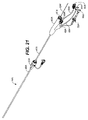
システム10は二重壁充填構造体12を動脈瘤に送り出すためのものであり、充填構造体と、拡張可能な部材、一般には膨張可能なバルーン16をその遠位端に有するデリバリカテーテル14とを含む。カテーテル14は、ガイドワイヤ内腔18と、バルーン膨張内腔(不図示)または別の拡張可能な構成部品を拡張するための別の構造と、充填剤または充填素材を二重壁充填構造体12の内部空間22に送り出すための充填管20とを備えている。内部空間22は、充填構造体の外壁24と内壁26との間に画定される。充填素材または充填剤が膨張すると、外壁は破線で示すように、径方向外側に拡張し、内壁26も破線で示すように拡張する。内壁26の拡張は内部内腔28を画定する。拡張可能なバルーン16または別の充填構造体は拡張可能であり、図1の破線で示すように、内腔28の内面を支持する。
The
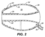
ここで図2を参照すると、内面および外面は様々に形状を取り、被覆、処理、その他の方法で改質されて本発明の機器の複数の潜在的に望ましい特徴を提供してもよい。たとえば、外壁の外面24’は、一般に成形、蒸着、またはその他の製造工程時に構造素材に形成されるリング、点刻、またはその他の特殊な表面26’を有する形状としてもよい。外面も素材29で被覆されていてもよい。素材29は接着剤、薬品、活性物質、繊維、植毛、発泡体、または様々なその他の素材であってもよい。ほとんどの場合は、このような特殊な表面または改質は、治療される動脈瘤の内面に外壁24を密封、または取り付けることを強化することを目的とする。
Referring now to FIG. 2, the inner and outer surfaces may be variously shaped and modified by coating, processing, or other methods to provide a plurality of potentially desirable features of the device of the present invention. For example, the
充填容積22の内面30も、前記表面26’、被覆、表面粗面処理、素材29を用いる被覆、または様々なその他の改質を施すことによって改質されてもよい。このような内部特徴の目的は一般に、充填剤が硬化またはその他の方法で固化するときに、壁を充填素材または充填剤にしっかりと接着させることである。ある事例では、内面30のすべてまたは一部に素材を被覆し、挿入されるときに充填素材の固化を誘発または触媒してもよい。
The inner surface 30 of the
二重壁充填構造体12は一般に、少なくとも1つの弁35を備え、充填管20を用いて充填素材または充填剤を内部容積22に導入できるようにしている。例示するように、弁35は単一のフラップ弁であってもよい。別のより複雑なボール弁、および別の一方向弁を備えていてもよい。別の事例では、二方弁構造を備えて内部容積22を充填することと、選択的に空にすることの両方を行ってもよい。別の事例では、充填管は、弁35を貫通する針または別の充填構造体を備え、充填剤の充填および除去の両方を行なえるようにしてもよい。
Double
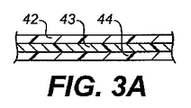
図2に例示するように、二重壁充填構造体の壁構造は単一層でもよく、一般に成形またはその他の従来の方法で形成してもよい。壁構造は、たとえば図3A−図3Cに例示するように、より複雑であってもよい。図3Aは層42、43および44を備えた多層壁を示す。このような多層構造によって、強度の強化、耐穿孔性、柔軟性および/または可撓性の変化、耐劣化性の違いなどを提供することができることが理解されよう。図3Bに示すように、単一壁または多層壁構造は、網、コイル、または他の金属または非重合性強化層または構造48によって増強することもある。図3Cに示すように、壁の外面24’は薬品、繊維、突起、穴、活性物質または様々な用途のための別の物質で被覆されてもよい。
As illustrated in FIG. 2, the wall structure of a double wall filled structure may be a single layer and may generally be formed or formed by other conventional methods. The wall structure may be more complex, for example as illustrated in FIGS. 3A-3C. FIG. 3A shows a multilayer wall with
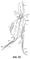
ここで図4を参照すると、腎動脈腹部大動脈瘤の解剖学的構造は、腎動脈(RA)をその遠位端に、腸骨動脈(IA)の上部に有する胸部大動脈(TA)を備えている。腹部大動脈瘤(AAA)は一般に、腎動脈(RA)と腸骨動脈(IA)との間に形成され、その内面(S)の一部上に壁在血栓(T)領域を有することもある。 Referring now to FIG. 4, the anatomical structure of the renal artery abdominal aortic aneurysm comprises a thoracic aorta (TA) having a renal artery (RA) at its distal end and an upper portion of the iliac artery (IA). Yes. An abdominal aortic aneurysm (AAA) is generally formed between the renal artery (RA) and the iliac artery (IA) and may have a mural thrombus (T) region on a portion of its inner surface (S) .
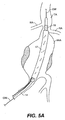
図5A−図5Dを参照すると、図1のシステム10を使用して、図5Aからよく分かるように、腎動脈(RA)下部の大動脈領域から腸骨動脈(IA)上の領域まで動脈瘤を一般に覆って、(未充填構成の)二重壁充填構造体12を配置するように、デリバリカテーテル14をまず配置することによって、図4の複雑な幾何形状の経壁腹部大動脈瘤(AAA)を治療してもよい。通常、デリバリカテーテル14は、セルディンガー法によって、患者の鼠径部の穿刺部を貫通するガイドワイヤ(GW)を通じて導入され、腸骨動脈からアクセスする。
Referring to FIGS. 5A-5D, using the
二重壁充填構造体12が適切に配置された後、固化可能膨張媒体は内部空間22内に導入され、内部空間22を充填し、構造の外壁24を外向きに拡張する。これによって、外壁24は動脈瘤空間の内面(S)に合致する。
After the double
図5Bに例示するように、膨張媒体を二重壁充填構造体12に充填する以前、充填中、または充填後に、バルーン16または別の拡張可能構造も膨張または拡張して、内壁26の内部によって画定される管状内腔が開かれる。通常、非柔軟性バルーン16を使用する。非柔軟性バルーン16は、一般に、展開された二重壁充填構造体12を貫通する所望の管状内腔の直径または幅であるか、またはそれよりわずかに大きい最大径または幅を有する。対照的に、充填構造体12は、部分的にまたは完全に、一般に柔軟性材料から形成されており、したがって、図5Cに例示するように、非柔軟性バルーン16または別の拡張可能構造が、管状内腔を完全に開き、内腔の端部を大動脈壁と腸骨動脈壁とに合致させることが可能になる。管状内腔の下方または遠位端50は大きな直径になるまで広がってもよく、これによって、例示する腸骨動脈(IA)の両方につながる開口を収容することができる。充填構造体12の幾何形状は、治療前の計画で決定するように、処置される特定の患者の幾何形状に最も適合するように選択することができる。管状内腔の下方または低遠位端50を、上方または近位端52より大きな直径に優先的に開口するように形成されるバルーン16または別の拡張可能構造を使用することもできる。
As illustrated in FIG. 5B, the
充填素材が、通常、充填管20を通じて充填構造体12に導入された後、流体充填素材は、特定の動脈瘤幾何形状で所定の場所に留まり、一般に固定された構造を有する永久インプラントを実現するために、硬化するか、またはその他の方法で固化されなければならない。充填素材を硬化または固化させる方法は、充填素材の性質によって異なる。たとえば、あるポリマは、熱エネルギまたは紫外光などのエネルギを加えることによって硬化させてもよい。別のポリマでは、体温、酸素、または流体充填素材の重合を引き起こす別の条件にさらすことによって硬化させてもよい。さらに別のポリマは、使用直前に混合され、一定時間後、通常、数分後に単に硬化するものもある。多くの場合、充填素材が固化した後、デリバリカテーテル14は取り除かれ、充填構造体が、完成した人工器官インプラントとして所定の場所に残される。
After the filling material is typically introduced into the filling
しかし、別の場合には、グラフトの近位端52または遠位端50に、一定の封止、固定、ステント、または別の付加的な人工器官構成部品をさらに配置することが望ましい場合がある。たとえば、図5Dに例示するように、ステント状の構造体160を充填構造体12の管状内腔の上部近位端開口内に埋め込んでもよい。これによって、構造体を固定し、外壁24と動脈瘤の内面(S)との間の領域内に血液が侵入するのを防止するのに役立ち、大動脈から管状内腔への移行を全体的に改善する。封止または固定構造は、血流が(もしあれば)覆われた腎動脈内に入ることを可能にするポートまたは別のアクセス経路を好ましくは有するステント状の構成部品を単に備えていてもよい。あるいは、固定構造は、そのすべての開示が参照により本明細書の理解に役立つ同時係属中の所有者が共通である米国特許出願番号第2004/0116997号に記載される固定要素などの別の膨張可能ユニットであってもよい。
However, in other cases, it may be desirable to further place a seal, anchor, stent, or another additional prosthetic component at the
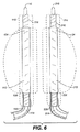
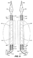
特定の実施形態では、図5A−図5Cに例示するような単なる単一の充填構造体の代わりに、1対の二重壁充填構造体を同時に使用して、腎動脈下腹部大動脈瘤を治療する。第1の充填構造体112と第2の充填構造体212とを含む1対の充填構造体を備えたシステムを図6に示す。各充填構造体112、212は、それぞれデリバリカテーテル114、214上に取り付けられる。充填構造体112、212とデリバリカテーテル114、214の構成部品は、図1の単一の充填構造体システム10に関して前述したものと概ね同じである。各充填システム112、212の対応する部品は、100番台の基本番号または200番台の基本番号のいずれかを有する同一の番号で示されている。一方、充填構造体112、212と図1の充填構造体12との間の違いは、以下の図7A−図7Fを特に参照して説明するように、充填構造体の対がわずかに小さい充填容積構造を持つことである。これは、充填構造体の対は、動脈瘤の空間内で互いに隣接して配置され、動脈瘤の空間を一緒になって充填することが意図された、動脈瘤容積のおよそ補完的な半分を占めるだけでよいためである。
In certain embodiments, a pair of double-walled filling structures are used simultaneously to treat a subrenal abdominal aortic aneurysm instead of just a single filling structure as illustrated in FIGS. 5A-5C. To do. A system with a pair of filling structures including a
図6に例示する充填構造体112、212の対を使用して腎動脈下腹部大動脈瘤を治療する際には、図7Aに例示するように、まず1対のガイドワイヤ(GW)を各腸骨動脈(IA)から1本ずつ導入する。次に、図7Bに例示するように、第1のデリバリカテーテル114を、二重壁充填構造体112が大動脈瘤(AAA)を覆って配置されるように、一方のガイドワイヤ上に配置する。次に、図7Cに例示するように、第2のデリバリカテーテル214を、第2の充填構造体212が動脈瘤(AAA)内で第1の充填構造体112に隣接して配置されるように、もう一方のガイドワイヤ(GW)上に送り出す。下記で説明するように、2つの充填構造体と関連するバルーンを同時に拡張させ、部分的に充填された(充填中の)充填状況を図7Dに例示する。図7Dでは、充填構造体112とバルーン116を同時に膨張させて、動脈瘤の容積を充填しているところを示す。完全に充填した状態を図7Eに例示する。バルーン116と216の上端は、充填構造体の管状内腔を大動脈の壁面に対してならびに互いに対して合致させ、バルーン116と216の下端は、管状内腔をそれぞれの腸骨動脈(IA)内に合致させる。
When treating a renal artery lower abdominal aortic aneurysm using the pair of filling
充填構造体112、212を図7Eに例示するように充填した後に、充填素材または充填剤は硬化またはその他の方法で固化され、デリバリカテーテル114、214がそれぞれ除去される。次に、硬化された充填構造体は、図7Fに破線で示すように、腎動脈下部の大動脈から左右の腸骨動脈に1対の管状内腔開口を提供する。図7Fに示すように、充填構造体112、212が動脈瘤の内面(S)に合致できることにより、充填構造体が動脈瘤内で少ししか、または全く移動せずに確実に固定化されることに役立つ。図2の実施形態に関連して上記で説明した任意の特殊な表面を設けることによって、充填構造体112、212の固定化をさらに強化してもよい。図示しないが、任意選択の固定または封止構造を、管状内腔の上側または近位のいずれかの開口から大動脈内まで、あるいは遠位または下側のいずれかの開口からそれぞれの各腸骨動脈内まで設けることができる。
After filling the filling
ここで図8を参照すると、二重壁充填構造体12(本開示ではエンドグラフトともいう)を動脈瘤に送り出すように構築されるシステム10が示されている。システム10は、半径方向に拡張可能なエンドフレーム19上に配設される充填構造体12を含む。エンドフレーム19と充填構造体12の両方は、次に内部デリバリカテーテル軸17上に取り付けられる。内部デリバリカテーテル軸17は、拡張可能な部材、一般に膨張可能なバルーン16をその遠位端近くに、および円錐状頭部33をその遠位端に有する。円錐状頭部33は、脈管を通じてデリバリシステムを進めることを容易にするような形状とされていてもよく、充填構造体12の展開前、展開中、または展開後に血管造影を実施するための一連の側部ポート34を含んでいてもよい。外部シース40は内部デリバリカテーテル軸17上に摺動可能に配設される。内部デリバリカテーテル軸17の遠位端は円錐状頭部33の近位部分と接合され、それによって患者の脈管を通じてシステムを進めることが容易になる。拡張可能要素16は、エンドフレーム19の長さ全体を横切り、それによって拡張可能要素バルーン16が拡張すると(拡張したバルーン16’を破線で示す)、エンドフレーム19は半径方向に拡張してもよい。エンドフレーム19は充填構造体12の長さ全体を横切り、およびエンドフレーム19のほとんどは充填構造体12によって覆われる。ただし、エンドフレーム19は、充填構造体12を超えて覆われずに延在する近位および遠位領域を有していてもよい。充填構造体、エンドフレームおよび拡張可能な要素の長さは必要に応じて調整されてもよく、したがって相対的な長さは上記に開示した長さに限定されないことが当業者には理解されるであろう。二重壁充填構造体に関するさらなる詳細は、米国特許公開第2006/0212112号に開示され、エンドフレームの実施形態は米国特許出願公開第2010/0004728号に開示され、両方ともその全内容は、参照により本明細書の理解に役立つ。
Referring now to FIG. 8, a
カテーテル14は、ガイドワイヤ内腔(不図示)と、バルーン膨張内腔(不図示)またはその他の拡張可能な構成部品を拡張させる別の構造と、充填剤または充填素材を二重壁充填構造体12の内部空間22に送り出すための充填管20とを備えている。内部空間22は、充填構造体の外壁24と内壁26との間に形成される。充填素材または充填剤によって膨張することによって、外壁24は半径方向外側に拡張し(拡張した外壁24’を破線で示す)、内壁26も拡張する(拡張した内壁26’を破線で示す)。内壁26の拡張は、内側の一般に管状内腔28を形成し、動脈瘤内に充填構造体が展開した後に、この管状内腔28を通って血液が流れる。拡張可能なバルーン16または別の充填構造体はエンドフレーム19の拡張に対応して拡張可能であり、内腔28の内面を支持し形成する。本実施形態では、拡張可能なバルーンは円筒形であり、したがって一般に管状内腔28も円筒形となる。別の実施形態では、バルーンは血管の湾曲により正確に適合するように前もって形成されていてもよい。たとえば、大動脈瘤を治療する際には、先細の、前もって形成されたまたは湾曲したバルーンを使用してもよく、それによって内腔は大動脈に略合致する。血管のねじれに合致するように様々なバルーンの構造を使用してもよい。所望する内腔形状を得るために、前もって形作られる湾曲した、または先細のバルーンを、本明細書で開示する任意の実施形態で使用してもよい。
特定の実施形態では、図8に例示するような単なる単一の充填構造体の代わりに、1対の二重壁充填構造体を使用して、腎動脈下腹部大動脈瘤を治療する。第1の充填構造体112と第2の充填構造体212とを含む、このような1対の充填構造体を備えたシステムを図9に例示する。各充填構造体112、212は、それぞれデリバリカテーテル内部軸114および214上に取り付けられる。各システムは半径方向に拡張可能なエンドフレーム127、227も有する。内部デリバリカテーテル軸114、214は、治療前、治療中または治療後に血管造影を実施するための有窓の円錐状頭部133、233と、システムが脈管を通ってガイドワイヤ(GW)に沿って前進する際に、充填構造体上に摺動可能に配設される外部シース140、240とを含む。充填構造体112、212の構成部品、エンドフレーム127、227および内部デリバリカテーテル軸114、214は、一般に図8の単一充填構造体システム10に関して前述したものと同一である。各充填システム112、212の対応する部分は100番台の基本番号または200番台の基本番号のいずれかを有する同一の番号で示している。充填構造体112、212は一般に、以下の図10A−図10Iを特に参照して説明するように、動脈瘤の空間内で互いに隣接して配置されて、動脈瘤の空間を充填する。
In certain embodiments, a pair of double-walled filling structures are used to treat a subrenal abdominal aortic aneurysm instead of just a single filling structure as illustrated in FIG. A system comprising such a pair of filling structures, including a
図10A−図10Iは、壁在血栓Tを有するかまたは壁在血栓Tが腎動脈下腹部大動脈瘤AAAを治療するための、図9のシステムの代表的な使用方法を例示する。内部デリバリカテーテル軸114、214を前進させ、充填構造体112、212を治療部位に配置し、外部シース140、240を内部カテーテル軸114、214に対して後退させる。外部シース140、240は充填構造体112、212上に摺動可能に配設され、対応するエンドフレーム127、227はその中に配設される。図10Aでは、一対のガイドワイヤ(GW)が、まず好ましくは経皮的にまたは外科的切開を通じて各腸骨動脈(IA)から導入され、腎動脈(RA)に向かって動脈瘤を覆って前進する。ここで図10Bを参照すると、第1のデリバリカテーテル軸114は有窓の円錐状頭部133を遠位端に有し、拡張可能なバルーン116を遠位部分に配設する。第1のデリバリカテーテル軸114は、一方のガイドワイヤGW上を前進し、二重壁充填構造体112をエンドフレーム127と共に大動脈瘤(AAA)を覆って配置する。外部シース140は摺動可能に充填構造体112および内部軸114上に配設されているが、充填構造体112を対象治療部位において露出するために後退させる。拡張可能なバルーン216と、その遠位端に有窓の円錐状頭部233を有する第2の内部カテーテル軸214は、次に他方のガイドワイヤGW上に送り出され、図10Cに例示するように、第2の充填構造体212を、エンドフレーム227に沿って動脈瘤(AAA)を横切るように、第1の充填構造体112に隣接して配置する。外部シース240は充填構造体212および内部軸214上に摺動可能に配設されるが、第2の充填構造体212を対象治療部位で露出するために後退させる。
FIGS. 10A-10I illustrate an exemplary use of the system of FIG. 9 for having or having a mural thrombus T to treat a renal abdominal abdominal aortic aneurysm AAA. The inner
代表的な方法では、まず、バルーン116または216を拡張する。拡張するバルーン116または216は、対応する充填構造体112または212、およびその上に配設されるエンドフレーム127、227を拡張する。次に、拡張された充填構造体112または212は液体充填剤で充填される。次に、バルーン116または216は収縮して、液体充填剤で充填された充填構造体112、212を血流が流れるようにする。その一方で、拡張されたエンドフレーム127、227は、拡張されて充填された充填構造体112または212内の略管状内腔の開通性を維持する。別の実施形態では、充填構造体112または212のうちの1つまたは両方が、まず、液体充填剤で充填される。次にバルーン116または216が拡張し、エンドフレーム127または227を拡張して、対応する充填構造体112または212内に一般に管状内腔を形成する。さらに別の実施形態では、充填構造体112または212は、その内部に配設される拡張するバルーン116または216と同時に、液体充填剤で充填する。展開手順の一般的な変形は、充填構造体112、212および関連するバルーン116、216のうちの1つが、まず対応するエンドフレーム127、227と共に拡張され、次にその他の充填構造体、エンドフレームおよびバルーンを拡張する手順を含んでいてもよい。下記の構成で説明するように、両方のバルーンを半径方向に同時に拡張すると、充填構造体およびエンドフレームも同時に拡張する。
In a typical method, the
代替的に、1つまたは両方の充填構造体112、212を固化可能素材で充填し、次に充填構造体112、212を対応するエンドフレーム127、227と共に半径方向に拡張してもよい。さらに別の実施形態では、医師の好みおよび動脈瘤の解剖学的構造によって、充填と拡張の組み合わせを異なる順序で行ってもよい。ある実施形態では、任意に選択した予備の充填段階を、固化可能充填剤を用いて充填前に実施してもよい。この任意な選択段階では、デリバリシステムが動脈瘤を覆って配置されると、充填構造体にC02ガス、造影剤、食塩水または別の流体を充填して充填構造体12をデリバリカテーテルから離れるように拡げてもよく、それによって後の充填を確実により均等にし、充填構造体の折り目間に存在することもある静摩擦を低減または削除する。展開中には、充填構造体は、部分的にまたは完全に充填されるため、充填構造体は内部動脈瘤壁に合致する。展開されると、動脈瘤上流の内部カテーテル軸114または214上にある有窓の円錐状頭部133または233を通じて血管造影を実施し、展開した充填構造体112内の漏れを検出する。エンドリークの発生を防止するために最適の充填容積および圧力が決定されると、液体は充填構造体から除去され、充填構造体は固化可能素材で充填されて拡張し、内腔と内部動脈瘤壁との間の動脈瘤空間に合致する。本明細書に開示するものなどの圧力安全弁を用いて、充填構造体が過剰充填しないようにすることもできる。充填構造体の過剰充填を防止するために、下記で開示する任意の圧力安全弁を使用して、充填構造体から余分な液体を排出してもよい。
Alternatively, one or both filling
図10Dは、充填構造体112、212の拡張および充填に加えて、バルーン116、216の両方をエンドフレーム127、227と共に同時に膨張するところを例示する。図10Eに例示するように、充填構造体およびバルーンは拡張されて膨張し、動動脈瘤壁および互いに接触する動脈瘤容積を充填する。米国特許公開第2006/0212112号は、1つの充填構造体の充填を、圧力、充填素材および別の詳細を含み、より詳細に開示する。その内容全体は従前の参照により本明細書の理解に役立つ。図10Eは、また充填された充填構造体112、212内の拡張されたエンドフレーム127、227の切断図も例示する。バルーン116、216の上側端部は、充填構造体の管状内腔を、互いに対して、および大動脈壁に対して合致させ、一方、バルーン116、216の下側端部は管状内腔をそれぞれの腸骨動脈IAに合致させる。拡張されたエンドフレーム127は充填構造体112への支持を提供するだけではなく、大動脈から一方の腸骨動脈までの血液流路のための内腔も作成し形成する。同様に、拡張されたエンドフレーム197も大動脈から他方の腸骨動脈までの血液流路のための内腔を提供する。ある手順では、充填構造体の充填(両方同時に、または1つずつ充填されるかのいずれか)は、バルーンおよびエンドフレーム127、227の半径方向の拡張前、拡張中または拡張後に(両方同時に、または1つずつ拡張されるかのいずれか)実施してもよい。さらに、図9に関して前述したように、エンドフレーム127、227は、円筒形のバルーンを使用して、略円筒形の内腔を形成するように半径方向に拡張してもよい。湾曲した、先細の、または前もって形成されたバルーンを使用して、エンドフレーム127、227を拡張し、それによって、同様に湾曲した先細のまたは形成された内腔を形成してもよい。湾曲した、先細のまたは前もって形成されたバルーンを選択して、内部にエンドフレームおよびエンドグラフトが配置される血管の解剖学的構造に適合させてもよい。前もって形成されている湾曲した、または先細のバルーンを、本明細書に開示する任意の別の実施形態で使用して、所望の内腔形状を得ることもできる。
FIG. 10D illustrates the expansion and filling of the filling
図10Eに例示するように、充填構造体112、212を充填後、充填素材または充填剤は、米国特許公開第2006/0212112号に記載するように、硬化またはその他の方法で固化され、内部デリバリカテーテル軸114および214はそれぞれ除去される。図10Fの破線に明確に示すように、固化した充填構造体は拡張されたエンドフレーム127、227と共に、次に一対の管状内腔開口を、腎動脈下部の大動脈から左右の腸骨動脈まで提供する。充填構造体112および212が動脈瘤の内面(S)に合致できることによって、図10Fに示すように、構造が動脈瘤内で少ししか、または全く移動せずに確実に固定化されることを助ける。その内容が参照によって本明細書の理解に役立つ米国特許公開第2006/0212112号で説明した任意の特殊な表面を設けることによって、充填構造体112および212の固定化をさらに強化することもできる。
After filling the filling
二重充填構造体の実施形態は、各管状血流内腔内に展開する少なくとも1つのエンドフレームを含んでいてもよい。エンドフレームは、一般に新しい内腔の基礎を築く骨格状の構造であり、二重壁充填構造体の管状内腔内に、バルーンまたは別の拡張カテーテル(可鍛性またはバルーンで拡張可能なエンドフレームの場合)および任意に選択した後退可能な抑制シースを使用して展開される。図10Gは、第1の充填構造体112の一般に管状内腔内に配設される第1のエンドフレーム127をより明確に示す。一方、第2のエンドフレーム197は第2の充填構造体212の管状内腔に配設される。例示するように、この代表的な実施形態では、エンドフレームはバルーンで拡張可能な構造であり、充填構造体の下側端部において腸骨動脈IAに延在する。別の実施形態では、エンドフレームは、ニチノールなどの形状記憶合金から形成された自己拡張するエンドフレーム状の構造である。
Embodiments of the double filling structure may include at least one end frame that deploys within each tubular blood flow lumen. An end frame is a skeletal structure that generally lays the foundation for a new lumen, and a balloon or another dilatation catheter (a malleable or balloon-expandable end frame within the tubular lumen of a double-walled filling structure. ) And an optional selected retractable restraining sheath. FIG. 10G more clearly shows the
ここで図10Hに示すように、第1および第2のエンドフレーム127、227は、第1および第2の充填構造体112、212の動脈側の上方に延在してもよい。このような実施形態では、第1および第2のエンドフレーム127、227は、腎動脈を妨害しないように構成されている。たとえば、第1および第2の充填構造体112、212は、血流が腎動脈(RA)を流れるように側部の穴を含んでいる。エンドフレーム構造が胸部大動脈TAに延在する場合は、エンドフレーム構造は、接面または領域に沿って互いに対して合致するように拡張されることが好ましい。たとえば、図10Iに示すように、エンドフレーム127、227の上側端部は、バルーンおよび製造された形状それぞれの拡張によって、拡張したときにD字型の断面を有するように形成されてもよいが、楕円形、円形などのその他の断面に形成してもよい。このように、平らな面258および260は互いに、大動脈の内壁に合致するエンドフレームの残りの部分と係合する。このようにして、大動脈の断面領域のほとんどがエンドフレームに覆われることによって、充填構造体を流れる血流を促進する。別の構成は、従前に参照により本明細書の理解に役立つ米国特許公開第2006/0212112号に開示される。
Here, as shown in FIG. 10H, the first and second end frames 127, 227 may extend above the arterial side of the first and second filling
図10A−図10Iの代表的な実施形態では、各エンドフレームおよび充填構造体は両方とも、デリバリカテーテルに接続する拡張可能な部材上に同軸および、一般に同心円状に配設される。システム全体が同時に動脈瘤に送り出される。このような同軸および同心システムは、図8に示すように、一般に充填構造体12を含み、エンドグラフトとも称され、エンドフレーム19上に同軸に配設される。充填構造体12とエンドフレーム19の両方は次に、同軸および同心円状に、半径方向に拡張可能なバルーン16上に配置される。バルーン16は内部軸17の遠位領域に結合する。エンドフレーム19の近位および遠位部分は充填構造体12によって覆われずに延在してもよい。充填管20によって流体は充填構造体12まで送り出される。一定の条件下でエンドリークが発生する。その結果として、動脈瘤の不完全な閉塞が起こる。個別の血管造影カテーテルは、動脈瘤を流れる血流を可視化し、展開中のエンドリークを検出するためには有用ではあるものの、個別の血管造影カテーテルによって断面が増大し、送り出し方法がさらに複雑になる可能性が高い。さらに、一定の状況では、充填構造体は送り出し中に、エンドフレームに対して移動することもあり、その結果として片方または両方の装置の不正確な配置が起こる。したがって、統合システムが、デリバリシステムの断面を実質的に増加せずに、または手順を過剰に複雑にせずに、血管造影手術を実施することができるシステムを提供することが有利である。このようなシステムが、充填構造体およびエンドフレームをデリバリカテーテルに接続して、移動を阻止し、エンドフレームおよびエンドグラフトを治療部位により正確に送り出すさらに効果的な方法を提供できるとさらに有利である。
In the exemplary embodiment of FIGS. 10A-10I, each end frame and filling structure are both coaxially and generally concentrically disposed on an expandable member that connects to a delivery catheter. The entire system is delivered to the aneurysm simultaneously. Such a coaxial and concentric system, as shown in FIG. 8, generally includes a filling
図1lA−図11Bは、有窓の円錐状頭部33および後退可能な外部シース40を有するデリバリシステムの代表的な実施形態を例示する。図示するように、図11Aはシステムを動脈瘤に送り出し中の図であり、図11Bは充填構造体12を動脈瘤において展開中の図である。代表的な実施形態は、充填構造体12およびエンドフレーム19がその上に配設されている内部軸17と、内部軸17上に摺動可能に配設される外部シース40と、充填構造体12と、エンドフレーム19とを含む。内部軸17の遠位端に取り付けられた円錐状頭部33は、その内部に延在する内腔、好ましくは単一貫通内腔を有する。貫通内腔は内部軸17のガイドワイヤ内腔に接続され、それによって円錐状頭部および内部軸は、同一のガイドワイヤGWに沿って同時に前進することができる。円錐状頭部33は、一連の側部ポート34を有する。側部ポート34は、充填構造体12の展開前、展開中、または展開後に血管造影を実施するために貫通内腔と連通している。システムは、解放可能な接続機構を含み、システムを動脈瘤まで送り出し中に、充填構造体12およびエンドフレーム19を内部デリバリカテーテル17に取り付ける(図20A−図20Eに詳細に示す)。図11Aに例示するように、外部シース40の遠位端は解放可能に円錐状頭部と接続し、患者の脈管を通じてシステムが前進することを促進する。マーカバンド31は、円錐状頭部33の近接部分と外部シース40の遠位端の一方または両方の接面近くに配設してもよい。これによって、ユーザは充填構造体12に対する外部シース40の位置を可視化することができる。充填構造体が所望の位置に配置されると、図11Bに示すように、外部シース40を充填構造体12および内部軸17に対して後退させることができ、それによって動脈瘤内で展開するために充填構造体が露出される。有窓の円錐状頭部は充填構造体12遠位の内部軸17の端部に取り付けられたままであり、血管造影手術を実施することができる。たとえば、図11Bに示すように、造影剤38を、内部軸17のガイドワイヤ内腔を通じて注入し、円錐状頭部33の側部ポート34から脈管内に排出してもよい。一実施形態では、図15に示す環状のノブ57の近くを引っ張ることによって外部シース40は後退する。充填構造体およびエンドフレームは内部カテーテルから展開および解放された後に、一般にノブ57を使用して、外部シース40を前進させることができ、これによって円錐状頭部33と接触してシステムを患者から引き出すことが容易になる。
FIGS. 11A-11B illustrate an exemplary embodiment of a delivery system having a windowed
図12は、デリバリシステムの代表的な実施形態を示し、有窓の円錐状頭部33と、外部シース40と、外部シース40内部に配設される充填構造体12(不図示)と、外部シース40を後退するための環状のキャリアノブ57と、ハンドル60とを含む。動脈瘤を治療する代表的な方法では、図12に示すようなシステムは患者の脈管に挿入される。円錐状頭部33の遠位の先細形状および、円錐状頭部33と、円錐状頭部33に接続した外部シース40との間の円滑な移動によって、患者の脈管を通ってシステムが前進することが容易になる。充填構造体12が動脈瘤治療部位に配置されると、医師はキャリアノブ57を近くに引くことによって、外部シース40を後退してもよい。それによって外部シース40をノブ57に近接するハイポ管41に後退する。キャリアノブ57は外部シース40の近位端に取り付けられ、外部シース40とハイポ管41との間の封止を含む。ハンドル60は内部軸17の近位端に配設され、システムを前進および後退させるためならびに(充填可能な)充填構造体12を展開するため、または円錐状頭部33を通じて血管造影を実施するために使用される。
FIG. 12 illustrates an exemplary embodiment of a delivery system, which includes a windowed
有窓の円錐状頭部
図13は図12の実施形態の円錐状頭部33をより詳細に例示する。図12の実施形態においてもされているが、円錐状頭部33を本明細書に開示する任意の実施形態に組み込んでもよい。円錐状頭部33は遠位に先細であり、円錐状頭部の長手方向軸に沿って延在するガイドワイヤ内腔32を含み、脈管を通じてガイドワイヤ上をシステムが前進することを容易にする。円錐状頭部33も有窓であり、血管造影を実施するために、貫通内腔と流体連通する一連の側部ポートを有する。円錐状頭部のガイドワイヤ内腔32は、ガイドワイヤと、側部ポート34を通じて血管造影を実施するための造影剤流を受領できるような大きさである。有窓の円錐状頭部33は、ガイドワイヤ上のシステムの前進と、ガイドワイヤを内腔内部に配設しながら、血管造影手術の造影剤を同一の内腔を通じて送り出すこととの両方が容易になり、それによって細い断面を維持しながら手術が簡略化されるため有利である。
Windowed Conical Head FIG. 13 illustrates in more detail the
システムの前進と充填構造体の展開の両方を促進するために、有窓の円錐状頭部33は外部シース40の遠位端と解放可能に接続または接面している。代表的な実施形態では、円錐状頭部33は等直径部分36を有する。等直径部分36は、外部シース40の遠位端の外径と等直径であり、接面において円滑に移動することができ、システムが患者の脈管を通って前進するにつれて血管の壁に対して「除雪する(snowplowing)」ことを防ぐ。等直径部分36は接面の近接する距離まで延在することによって、接面近くの円錐状頭部の硬さを増強し、システムが前進中に円錐状頭部および/または接面での外部シースが歪むことを防ぐ。円錐状頭部33はまた、外部シース40の遠位端の内径よりわずかに小さい外径を有する部分37も含んでいてもよい。このように、部分37が外部シース40内に配設されることによって外部シース40はぴったりと部分37を受容し、円錐状頭部33と解放可能に接続する。部分37は接面に近接する距離まで延在してもよく、これによって接続の固定化が強まり、接面近くの硬さが強まり、システムが複雑な、または屈曲した脈管を通って進むにつれて円錐状頭部と外部シース40が分離することを防ぐ。これによってさらに円錐状頭部33と外部シース40間の円滑な移動を強化し、血管壁に対する「除雪」の可能性を低減する。円錐状頭部33および/または外部シース40は、さらに、X線不透過性のマーカバンド31を接面近くに設けていてもよく、これによって医師は外部シース40遠位端の円錐状頭部33に対する位置を撮像できるようになる。円錐状頭部を製造するための樹脂は、手術中の撮像を容易にするために、X線不透過性の充填剤も含んでいてもよい。
To facilitate both system advancement and filling structure deployment, the windowed
円錐状頭部33は患者の脈管内を前進しやすい大きさに作られている。代表的な円錐状頭部は、長さ1から4インチまで、好ましくは2.5から3インチまでであり、近位端での約0.25インチから遠位端での約0.050インチまで先細の外形を有する。円錐状頭部33を貫通して延在するガイドワイヤ内腔32も、外径が先細になるにつれて、大きさが小さくなってもよい。たとえば、近位端32Bでの貫通内腔は0.05と0.1インチとの間、好ましくは約0.08インチであり、0.02から0.04インチまで徐々にまたは増加的に細くなっており、好ましくは円錐状頭部33の遠位部分32Aでは約0.05インチである。
The
血管造影は、造影剤を内部軸17のガイドワイヤ内腔を通じて注入することによって実施されてもよい。造影剤は次に、好ましくはガイドワイヤGWがガイドワイヤ内腔32内に配設されながら、円錐状頭部33のガイドワイヤ内腔32内に流入し、側部ポート34から排出される。血管造影は、動脈瘤の治療前、治療中または治療後に、円錐状頭部33を通じて実施されてもよい。血管造影は血流を撮像するために有用であり、具体的には動脈瘤内に展開したエンドグラフト内での漏れを検出するために有用である。血管造影手術では、X線不透過性の造影剤は血管に送り出され、X線透視法などのX線を用いる撮像技法を用いて血管を流れる造影剤の流れを撮像する。このように、造影剤は血管内に均等に放出されるため、撮像は血管を流れる血流をより正確に表示することができる。
Angiography may be performed by injecting contrast agent through the guidewire lumen of the
多くの実施形態では、有窓の円錐状頭部33は対の側部ポート34を有する。側部ポート34は円錐状頭部に沿って、らせん状に連続して等間隔に配分して配置され、これによって造影剤は脈管に均等に配分される。好ましくは、各側部ポート34は円錐状頭部の長手方向軸33から垂直方向に開口している。代表的な実施形態では、円錐状頭部33は、前述したようにらせん状に配置される一連の4対から10対の側部ポート34、好ましくは5対から7対の側部ポートを備えている。一般に、側部ポート34は0.01インチから0.05インチまでの範囲の直径を有し、より好ましくは、0.03インチから0.04インチまでの範囲の直径を有する。
In many embodiments, the windowed
図14は、ガイドワイヤ内腔32内に配設されるガイドワイヤGWを有する円錐状頭部33と、ガイドワイヤ内腔32の部分を通じて流れる造影剤38の流れとを例示している。代表的な実施形態では、ガイドワイヤ内腔32は、円錐状頭部33の近位端で、ガイドワイヤ内腔32より大きさが小さい遠位部分32Aを有する。ガイドワイヤ内腔32の遠位部分32Aは、摺動可能にガイドワイヤを受容し、ガイドワイヤがその内部に配設されるときに、遠位開口を通って造影剤が流れることを防ぐように適合される大きさである。ただし、部分32Aのガイドワイヤ内腔32に近接する部分は、同時にガイドワイヤを受容し、造影剤38の流れを促進するような大きさである。ガイドワイヤ内腔32の狭窄遠位領域32Aは、円錐状頭部の遠位開口を通って造影剤が流れることを略阻止し、それによって、図14に例示するように、造影剤が側部ポート34を流れるように、そして患者の脈管を流れるように導く。
FIG. 14 illustrates the
環状ノブ
図15は、図12のシステムのキャリアノブ57を例示する。キャリアノブ57は、外部シース40の近位端とハイポ管41とを接続している。このような実施形態では、外部シース40は、外部シース40が後退している場合には、少なくとも部分的に、ハイポ管41(メインカテーテル軸)上に摺動可能に配設されている。使用時には、外部シース40は内部軸17に対して後退し、充填構造体12と、エンドフレーム19と、拡張可能な部材、つまりバルーン16とを内部軸17の遠位領域で露出させている。キャリアノブ57は、外部シース40の近位端に、好ましくは熱接着で固定され、これによって医師は手動でキャリアノブ57を引き、外部シース40をハイポ管41上に後退させてもよい。キャリアノブ57は、また内部封止も含んでいてもよい。キャリアノブ57は、ポリエーテルアミドなどの外部シース40と接着することができる任意の素材を備えていてもよい。
Annular Knob FIG. 15 illustrates the
キャリアノブ57は、外部シース40の遠位部分と近接部分との間に液体が流出しないように、シリコーンOリングなどの内部封止56を備えている。一般に、内部封止56に対する患者の血圧は、外部シース40とハイポ管41との間の本体から液体が流出することを防ぐために十分である。キャリアノブ57を手前に引っ張るにつれて、内部封止56は、ハイポ管41の外面および環状ノブ57の内部に接触して手前に摺動する。
The
キャリアノブ57は、外部シース40の近位端を積層素材、好ましくはペバックス(登録商標)などのポリマ素材によって被覆することによって、外部シース40に熱接着される。これによって、ノブ57の空洞を積層で被覆した外部シース40上に配置し、アセンブリを加熱して、積層を外部軸40および/またはノブ57に接着させ、好ましくは、両方の外部シース40の外面およびノブ57の内面の両方と接着する。システムはさらに、外部シース40が前進するときに、ハイポ管41がノブ57から滑り落ちないように保持機構を含んでいてもよい。保持機構は、カラー、リング、ピン、ねじまたはハイポ管41と環状のノブ57との間の摺動可能な接続を維持するために適切な任意の機構を備えていてもよい。システムは、またハイポ管41(メインカテーテル軸)とシース40との間の回転を防ぐために、施錠機構を含んでいてもよい。ノブ57は、シースを洗い流すことができ、または治療手術中にシースを通じて造影剤を送ることができるシースフラッシュライン63を有する。
The
ハンドル
図16は、図12の代表的なデリバリシステムのハンドル60を例示する。ハンドル60は、ガイドワイヤアクセスポート61を有する本体と、血管造影ライン62と、充填ライン64と、リリースワイヤポート/コネクタ66と、バルーン膨張ライン68とを含む。血管造影ライン62は、ガイドワイヤ内腔へのアクセスを提供し、これによってガイドワイヤ内腔を通じて造影剤を注入し、これを一連の円錐状頭部33の側部ポート34から排出することができる。造影剤は粘性であることもあるため、血管造影を実施するために必要な最終圧力は1,000psi以上となっている。この圧力によって、ガイドワイヤがガイドワイヤ内腔から「突き抜ける」可能性もある。そうならないように、ガイドワイヤアクセスポート61は、血管造影処置中に、ガイドワイヤGWをハンドルに係止するための係止機構を備えている。このように、血管造影ライン62は、ガイドワイヤ内腔へのアクセスを提供する一方、ガイドワイヤアクセス61はガイドワイヤGWを所定の位置に封止および係止する。リリースワイヤアクセスポート/コネクタ66は、リリースワイヤを除去するためのアクセスを提供し、これによって内部軸17から接続機構を切り離し、展開した充填構造体体を解放する。リリースワイヤアクセスポート/コネクタ66は、ねじ込みルアータイプのコネクタを備えている。ねじ込みルアータイプのコネクタはリリースワイヤの近位端に固定されている。これによって、ポートコネクタを(充填構造体充填管64と共に)除去し、手前方向に引くことによって、リリースワイヤを後退させ、接続機構を切り離すことができる。任意な選択として、ハンドル60は内部軸および外部軸上で回転して、不要なトルクがカテーテル軸に伝達されないようにする。図示した追加の構成部品の説明は、図18および図21の説明に含まれる。
Handle FIG. 16 illustrates the
圧力モニタ69を使用して、治療手術中の充填構造体の充填圧力を監視する。圧力モニタは充填管回路と流体接続されており、これによって、充填構造体12を固化可能充填剤で充填中に、システム充填圧力を監視する。
A pressure monitor 69 is used to monitor the filling pressure of the filling structure during the therapeutic procedure. The pressure monitor is fluidly connected to the fill tube circuit, thereby monitoring the system fill pressure while filling the filling
圧力監視
充填構造体と、エンドフレームを個別のカテーテルで同時に展開する代表的な方法では、圧力監視を次のような方法で使用する。2つの充填構造体を治療部位に送り出した後、両方のエンドフレームを半径方向に拡張して、血流が動脈瘤を覆う充填構造体を流れるように内腔を作成する。患者のコンピュータ断層(CT)スキャンからのデータを使用して、動脈瘤治療部位の充填容積を推測してもよい。これは両方の充填構造体にとって基本充填容積となり、充填構造体供給回路に注入すべき最小の充填素材の予想容積である。注射器または圧力計に接続する別の注入装置を使用して、任意な選択として、基本容積を使用して各充填構造体を造影剤で予備充填し、その結果生じる基本充填圧力を記録してもよい。さらに、圧力監視システムは安全弁を備え、過剰充填時には過剰な圧力を放出してもよい。圧力監視システムは、充填構造体内のセンサと、患者の示差血圧を計算するために用いる患者の収縮期血圧およびまたは拡張期血圧を監視するためのセンサとを含んでいてもよい。充填構造体と患者の収縮期血圧およびまたは拡張期血圧との間の示差血圧の測定値は、充填構造体を充填する手順を単純化できる。これは、医師が正確に充填構造体内の圧力を目標とすることができるためである。これによって、充填構造体が拡がることができ、拡張された充填構造体が動脈瘤空間に合致しているかの初期評価が提供される。これが実現すると、造影剤は充填構造体から(予備充填ステップを利用する方法で)除去される。再び患者CTデータを使用して、機能的な充填容積を決定してもよい。この容積はCTデータから得た動脈瘤容積の割合であっても、または規定する数字であってもよく、効率的に動脈瘤を封止および排除する充填素材の容積である。機能的な充填圧力は、機能的な充填容積が達成されるときの圧力である。ポリマ充填ディスペンサを使用して、次に、各充填構造体を機能的な充填容積まで充填し、機能的な充填圧力を記録してもよい。機能的な充填容積および圧力を保持しながら、充填構造体を蛍光透視下で観察し、適切な配置、充填および動脈瘤全体から漏れがないかを確認することができる。漏れが観測される場合は、漏れが阻止されるまで、または最小限となるまで、追加のポリマを充填構造体に追加してもよい。安全充填容積または安全充填圧力を超えないようにするために、充填構造体にポリマを過剰に追加してはならない。医師が充填構造体の充填および配置に満足すると、充填構造体の栓を閉鎖してポリマが固化できるようにし、次にデリバリ装置を患者から除去する。
Pressure Monitoring A typical method of deploying the filling structure and the end frame simultaneously with separate catheters uses pressure monitoring in the following manner. After delivering the two filling structures to the treatment site, both end frames are radially expanded to create a lumen such that blood flow flows through the filling structure overlying the aneurysm. Data from the patient's computed tomography (CT) scan may be used to infer the fill volume of the aneurysm treatment site. This is the basic filling volume for both filling structures and is the expected volume of the smallest filling material to be injected into the filling structure supply circuit. Using a separate infusion device connected to a syringe or pressure gauge, optionally using a basic volume to pre-fill each filling structure with contrast agent and recording the resulting basic filling pressure Good. In addition, the pressure monitoring system may include a safety valve to release excess pressure when overfilled. The pressure monitoring system may include a sensor within the filling structure and a sensor for monitoring the patient's systolic and / or diastolic blood pressure used to calculate the patient's differential blood pressure. Differential blood pressure measurements between the filling structure and the patient's systolic and / or diastolic blood pressure can simplify the procedure of filling the filling structure. This is because the physician can accurately target the pressure in the filling structure. This allows the filling structure to expand and provides an initial assessment of whether the expanded filling structure matches the aneurysm space. When this is achieved, the contrast agent is removed from the filling structure (in a manner that utilizes a pre-filling step). Again, the patient CT data may be used to determine a functional fill volume. This volume may be a percentage of the aneurysm volume obtained from CT data, or a prescribed number, and is the volume of filling material that effectively seals and eliminates the aneurysm. Functional fill pressure is the pressure at which a functional fill volume is achieved. Using a polymer fill dispenser, each fill structure may then be filled to a functional fill volume and the functional fill pressure recorded. While maintaining a functional filling volume and pressure, the filling structure can be observed under fluoroscopy to ensure proper placement, filling and leakage from the entire aneurysm. If leakage is observed, additional polymer may be added to the filling structure until leakage is prevented or minimized. To avoid exceeding the safe fill volume or safe fill pressure, do not add excessive polymer to the fill structure. When the physician is satisfied with the filling and placement of the filling structure, the plug of the filling structure is closed to allow the polymer to solidify and then the delivery device is removed from the patient.
図17は、統合圧力計変換器を備える圧力モニタ69を例示する。圧力モニタ69は、本体70と、圧力器具71と、制御ボタン72と、圧力および時間出力を測定するためのデジタル表示部73とを備えている。本体70は、圧力および/または示差圧力を決定するための圧力変換器を含んでいる。圧力器具71は本体70の圧力変換器を充填システムに接続する。制御ボタン72によってユーザは圧力または圧力もしくは時間読取値を調整することができる。圧力器具71は、デリバリシステム10の充填ラインと流体接続するための管状の部材およびルアーキャップを備えている。圧力モニタ69、またはその一部は、再利用可能であっても、または使い捨てであってもよい。圧力変換器は、一回限りの使い捨てであることが好ましい。さらに圧力計および図形表示など別の圧力表示器による実際の圧力監視も使用して、充填構造体の充填状態の決定を容易にすることもできる。たとえば、ある実施形態では安全弁を使用してもよい。安全弁は、事前に設定した圧力を超えると、任意の追加の充填素材が充填構造体から流出するように一定の圧力に事前に設定しておく。一方、安全弁は充填構造体に隣接してもよく、好ましくは充填素材はカテーテルの近位端(ハンドル端部)に向けて体外に排出される。これによって、潜在的に危険な流体または別の充填素材が体内に導入されることを防ぐ。
FIG. 17 illustrates a
本方法は、圧力監視システムを使用することも含んでいてもよい。このシステムによって、医師は充填構造体の充填前、充填中または充填後の圧力を監視することができる。システムは、圧力出力を表示するためのユーザインタフェースを含んでいてもよく、任意な選択として圧力出力と共に表示される時間出力を含んでいてもよい。監視システムは、圧力データを分析するためのプロセッサも含んでいてもよい。プロセッサは圧力データを正規化するためにプログラムされていてもよい。圧力監視システムによって、医師は密接に充填構造体を展開中の充填圧力を監視することができる。圧力監視システムは適切な展開を促進するために、測定した充填圧力が許容範囲外である場合は圧力カットオフスイッチおよび警告表示器、充填圧力を最適化し、充填中の圧力の変動を補償するための圧力ブリードオフスイッチを含む追加の機能を含んでいてもよい。監視システムは、また展開中の圧力データを記録することもできる。さらに、2つの充填構造体を展開する実施形態では、監視システムは動作可能に接続してもよく、それによってシステムまたは医師は、別の隣接する充填構造体からの圧力出力測定値に応じる1つの充填構造体の充填中の圧力を監視することができる。 The method may also include using a pressure monitoring system. This system allows the physician to monitor the pressure before, during or after filling of the filling structure. The system may include a user interface for displaying the pressure output, and may optionally include a time output that is displayed along with the pressure output. The monitoring system may also include a processor for analyzing the pressure data. The processor may be programmed to normalize the pressure data. The pressure monitoring system allows the physician to closely monitor the filling pressure during deployment of the filling structure. Pressure monitoring system to facilitate proper deployment, pressure cut-off switch and warning indicator when measured fill pressure is out of acceptable range, to optimize fill pressure and compensate for pressure fluctuations during filling Additional features including a pressure bleed-off switch may be included. The monitoring system can also record pressure data during deployment. Further, in embodiments where two filling structures are deployed, the monitoring system may be operatively connected so that the system or physician can respond to one pressure output measurement from another adjacent filling structure. The pressure during filling of the filling structure can be monitored.
圧力監視は、充填構造体の充填処置を制御するために動脈瘤修復手術の様々な段階でも実施することができる。圧力の監視は、過剰な圧力を受けて動脈瘤が解離、破裂または損傷する危険性を低減することに役立ち、また充填の終期を判断するために用いる。監視は、充填構造体を充填剤で充填および固化する以前、充填中および固化中または充填および固化後に行うことができる。監視可能な特定の圧力には、充填構造体の内部空間内の圧力ならびに充填構造体の外壁と動脈瘤の内壁との間の空間内の圧力がある。充填構造体の内部空間内で測定した圧力を、充填構造体の外壁と動脈瘤壁との間の空間内の圧力、または別の動脈瘤部位における空間内の圧力、ポンプまたは注射器などの液体送り出し装置が充填剤を送り出すために使用する外部送り出し圧力などと組み合わせて複合測定も行うことができる。制御の決定は、これらの圧力測定のうちの1つ、またはその組み合わせを用いて行うことができる。圧力監視の方法は、その内容全体が本明細書の理解に役立つ同一の出願人による関連特許出願である米国特許第7,666,220号および米国特許出願第20100036360号に詳細に記載されている。 Pressure monitoring can also be performed at various stages of aneurysm repair surgery to control the filling procedure of the filling structure. Pressure monitoring helps to reduce the risk of an aneurysm dissociating, rupturing or damaging due to excessive pressure and is used to determine the end of filling. Monitoring can be done before, during and after filling or after filling and solidification of the filling structure with filler. Specific pressures that can be monitored include the pressure in the interior space of the filling structure as well as the pressure in the space between the outer wall of the filling structure and the inner wall of the aneurysm. The pressure measured in the interior space of the filling structure is the pressure in the space between the outer wall of the filling structure and the aneurysm wall, or the pressure in the space at another aneurysm site, a liquid delivery such as a pump or syringe Combined measurements can also be made in combination with the external delivery pressure used by the device to deliver the filler. The control decision can be made using one of these pressure measurements, or a combination thereof. The method of pressure monitoring is described in detail in U.S. Pat. No. 7,666,220 and U.S. Patent Application No. 201306360, which are related patent applications by the same applicant, the entire contents of which are useful for understanding the specification. .
図17に示す圧力モニタは、オペレータが使用し、二重壁充填構造体12にポリマを充填しているときの充填圧力を監視する。最初に、後述するように、二重壁充填構造体12上で真空を引く。二重壁充填構造体12の充填がポリマの注入によって開始されると、図17に示すように、ポリマ管システム上の関連する圧力センサモニタは、二重壁充填構造体12が患者の動脈系の血液によって囲まれているため患者の全身の血圧を検出する。さらにポリマの注入が進み、系内の任意の圧縮可能な液体が圧縮される(ただし、展開操作の加圧部分の第1の段階の系上で真空が引かれるため、空気または別の圧縮可能な液体は系内にほとんどないはずである)。管システムが液体で充填されるにつれて(圧力を直ちに伝達する圧縮不能な液体であるため)、治療を受ける患者の血圧を計る圧力モニタの感度は増加する。次に、二重壁充填構造体12が抑制されず、患者の心臓の脈動によって通常の方法で加圧される全身の血液に囲まれている間、システムは単に圧力センサとして機能する。
The pressure monitor shown in FIG. 17 is used by an operator to monitor the filling pressure when the double
図17に示すような圧力モニタ69をプログラムして、平常時の患者の動脈機能において脈動血圧のサイクルの特定点における様々な所望の全身の血圧を表示することができる。高圧力は収縮期血圧であり、サイクルの低圧力は拡張期血圧である。圧力モニタをプログラムして、収縮期血圧と拡張期血圧の両方の読取値を(2つの測定値を1つの表示面に)表示することができる。圧力モニタ69を再プログラムして(ファームウェア調整)、特別に選択した圧力パラメータ、たとえば、収縮期血圧、拡張期血圧、または中間血圧(収縮期血圧と拡張期血圧との平均)を読み取ることができる。測定されて表示される圧力のサンプリング(平均)時間の長さもまた、圧力モニタ69で調整することができる。時間をかけた各パラメータの平均を選択した秒の範囲で取ることができる。たとえば、選択したサンプリング範囲は5秒、10秒、または15秒、または別の所望の間隔であってもよく、圧力監視装置のハードウェアおよびプログラム可能なソフトウェアにおいて利用可能である。圧力モニタは、次にデジタル表示を各選択した時間間隔で更新する。充填構造体を展開する際の通常の操作において、オペレータは二重壁充填構造体加圧システムにポリマを注入し、系の拡張期血圧を観察する。二重壁充填構造体の外壁が動脈瘤の内壁に届くまで、拡張期血圧は系圧力(患者の動脈血圧系圧力)にしたがって変化する。同時に、支持構造またはエンドフレーム(たとえば19)にすでに隣接している、またはその上に配置されている二重壁充填構造体の内壁は、内部支持構造またはエンドフレームに当接して位置していることの結果として、内側への拡張において制限される。対向していない拡張が制限まで拡張すると、二重壁充填構造体(エンドバッグ)内の圧力は増加する。拡張期血圧または中間血圧のいずれかで行われるようにプログラムされる圧力モニタの圧力読取値の監視は、二重壁充填構造体の拡張状態に関する情報を提供する。ポリマの注入/充填は、拡張期(低い)血圧が、収縮期血圧読取値の上の値と等しいか、または低くなるように増加するまで継続すべきである。これによって、圧力モニタ69の中間血圧および拡張期血圧読取値は、3つすべての圧力を様々な(当業者には既知の)手段によって表示または検出することができる事例において、操作中にはほとんど同一となる。エンドバッグが最大に拡張すると(動脈瘤の内壁によってそれ以上の拡張が制限されると)、圧力モニタ69はもはや系圧力を検知せず、変化系圧力を感知しない。拡張期血圧はあまり変動しない。二重壁充填構造体12(エンドバッグ)内の圧力をデジタル表示部73に表示する。エンドバッグの目標とする圧力は、通常は、治療を受ける患者の予想収縮期血圧よりも高いかまたはわずかに高い。全身の血圧が克服すると予測される圧力は180mmHgから300mmHgの範囲であり、気圧の半分未満(380mmHgに等しい)である。このように二重壁充填構造体の加圧は最初に全身動脈圧を読み取り、最終的に、動脈圧は除外され、二重壁充填構造体(エンドバッグ)の内部圧力のみが検出される。エンドバッグ内部の圧力が最大全身動脈圧より高くなると、かなり高い信頼度をもって、動脈瘤が除外されて封止されたといえる。この時点でポリマをさらに注入することは停止され、血管造影を使用して封止の確認を場合により行うことができる。最初の注入時間からポリマが硬化または設定されるまで5分から10分の時間がある。この5分から10分の間に、必要に応じてさらにポリマを注入し、二重壁充填構造体12の内部圧力を検出することが可能である。これらの態様は、本明細書に記載する任意の方法およびシステムで使用してもよい。
A pressure monitor 69 as shown in FIG. 17 can be programmed to display various desired systemic blood pressures at specific points in the pulsatile blood pressure cycle during normal patient arterial function. High pressure is systolic blood pressure, and low pressure in the cycle is diastolic blood pressure. The pressure monitor can be programmed to display both systolic and diastolic blood pressure readings (two measurements on one display surface). The pressure monitor 69 can be reprogrammed (firmware adjustment) to read specially selected pressure parameters such as systolic blood pressure, diastolic blood pressure, or intermediate blood pressure (average of systolic and diastolic blood pressure). . The length of the pressure sampling (average) time that is measured and displayed can also be adjusted by the
図18は代表的なデリバリシステムを例示し、図19A−図19Cは図18のデリバリシステムの断面を例示する。図19Aは、円錐状頭部に近接する位置の断面A−Aを示す。この位置では充填構造体12、エンドフレーム19およびバルーン16は、内部軸17の外側かつ外部シース40の内部にそれぞれ同心円状に配設されている。図19Bは、キャリアノブ57から遠位の位置にある断面B−Bを示す。この位置では、同心状の内部および外部充填管20A、20Bは、外部シース40の内部軸17の同心状の内部および外部バルーン軸17A、17Bと隣接して配設されている。図19Cは、ハンドル60とキャリアノブ57との間の位置の断面C−Cを示す。この位置では、同心状の内部および外部充填管20A、20Bは、ハイポ管41内の内部軸17の同心状の内部および外部バルーン軸17A、17Bと隣接して配設されている。多くの実施形態では、外部シース40およびハイポ管41は異なる素材を備えている。たとえば、外部シース40の遠位部分はポリエーテルブロックアミドであってもよく、一方、キャリアノブ57に近接する外部シース40の一部は304ステンレス鋼であってもよい。
FIG. 18 illustrates an exemplary delivery system, and FIGS. 19A-19C illustrate cross sections of the delivery system of FIG. FIG. 19A shows a cross section AA at a position close to the conical head. In this position, the filling
図19Bおよび図19Cは、バルーン外部軸に接着するバルーンの近接部から(腸骨側)約2.5cmで終端する内部コア99または充填剤も示す。内部コア99は一般に充填剤素材であり、(Dショア計のデュロメータで)硬さ70D以下のTPE素材(たとえばペバックス6333)であることが多い。内部コア99は、ペバックス6333などの低デュロメータ素材の固形であってもよい。または、内部コアの密度が押しやすさに貢献する限りペレセンを使用してもよい。内部コアの外面は円滑であってもざらざらしていてもよい。内部コアの表面設計を構成して、内部コアの表面と外部シースとの間の摩擦係数を所望の低さにすることができる。内部コア99の遠位端はバルーン先細/頸部への移動から約2cmから2.5cmの間で停止し、バルーンが拡張して、充填管のねじれを防止する。この移動は一般に熱形成およびUV接着されて、先細の移動を生成し、内腔を封止して空気が内腔内を通らないようにし、そしてバックブリードを防止する。ハンドル端部では、内部コアはハンドルハイポ管内の1cmで終結することもあり、またはハンドルハイポ管全体を通って延在することもある。理想的には、内部コアの少なくとも1cmはハンドルハイポ管内部に延在して、この位置で確実に取り付けてねじれを防止する。
19B and 19C also show an
デリバリシステム接続機構
図20A−図20Eは、代表的なデリバリシステムの接続機構を例示する。接続機構は、デリバリカテーテルに対する充填構造体およびエンドフレームの移動を防止し、それによって充填構造体およびエンドフレームを動脈瘤に配置することを容易にする。図20Aは、充填構造体が展開中の接続機構を描き、外部シース40は後退し、充填構造体12は部分的に充填されている。接続機構は、充填構造体12およびエンドフレーム19を内部軸17に取り付けるためのロープ51、53および/またはロープループを含んでいてもよい。図20Aに示すように、充填構造体12はエンドフレーム19上に配設されている。エンドフレーム19は、内部軸17の遠位端近くに配設された拡張可能な部材16上でひだが作られる。2つの解放可能な接続機構であるロープ51および53は、リリースワイヤ46とともに、動脈瘤まで送り出して配置する間の内部軸17に対する充填構造体12およびエンドフレーム19の移動を防止する。
Delivery System Connection Mechanism FIGS. 20A-20E illustrate a typical delivery system connection mechanism. The connection mechanism prevents movement of the filling structure and end frame relative to the delivery catheter, thereby facilitating placement of the filling structure and end frame in the aneurysm. FIG. 20A depicts the connection mechanism as the filling structure is deployed, the
ロープ51は、充填構造体12から離れた内部軸17に固定して取り付けられるロープループを備えている。図20Eに詳細に示すように、ロープループはエンドフレーム19の開口を貫通して延在し、リリースワイヤ46の周囲に延在する。ロープ51は、リリースワイヤ46がロープ51のループの中に留まる限り、エンドフレーム19を内部軸17に接続する。本実施形態では、エンドフレーム19は充填構造体12を縫合糸47にも接続するため、充填構造体12は内部軸17に間接的に接続される。リリースワイヤ46が後退すると、ロープループ51は容易にエンドフレーム19の開口からはずれて内部軸17と後退する。
The
ロープ53は、充填管20に固定して取り付けられるロープループを備えていてもよい。充填管20は次に、縫合ループ45を充填構造体12の近位端で貫通して延在し、リリースワイヤ46の周囲に延在する。リリースワイヤ46が縫合ループ45の内部に留まる限り、充填管20は充填構造体12の近位端との接続を維持する。ロープ53は、送り出し中に、充填構造体12の近接領域の移動を防止してもよく、充填管20が充填構造体12からはずれないように支援している。このように、ロープ53は、充填構造体の充填前および充填中、または再充填中に、手術が終了するまで二重安全機構を提供する。手術が終了すると、リリースワイヤは充填管20と充填構造体12との接続を解放して後退されてもよい。
The
充填構造体12が展開されて、固化可能な液体充填剤で充填されると、リリースワイヤ46をリリースワイヤ46の近位端をハンドル60から引くことによって、後退することができる。充填構造体12およびエンドフレーム19を解放後、ロープループ51、53はもはや充填構造体12またはエンドフレーム19をシステムに接続しないため、デリバリシステム10を本体から後退させることができる。代表的な実施形態では、リリースワイヤ46は、内部軸17の長さにわたって、かつ内部軸17と平行に延在する。送り出し中に、図20Dに詳細に示すように、リリースワイヤ46の遠位端は円錐状頭部33に非常に近接する内部軸17に解放可能に接続している。これによって、リリースワイヤは確実に充填構造体12の展開に干渉しない。ロックタイト3321などの紫外線硬化型接着剤を適用して結び目を保持し、リリースワイヤと内部軸との間を一時的に接着させてもよい。多くの実施形態では、リリースワイヤ46はテフロン(登録商標)で被覆されているため、医師がリリースワイヤ46の近位端をハンドル60で引くと、一時的な接着は容易に内部軸17から剥離および解除される。リリースワイヤ46はポリテトラフルオロエチレンで被覆した304ステンレス鋼から形成されてもよく、これによって展開後に充填構造体12とエンドフレーム19との間を容易に後退できるような大きさである。
Once the filling
図20Bに示すように、充填構造体12は、1または複数の縫合糸47、好ましくは、充填構造体12の遠位端の回りに等間隔で配設される4つの縫合糸によって、エンドフレーム19の遠位端と接続している。縫合糸47は充填構造体12をエンドフレーム19に接続して、展開中のエンドフレーム19の相対的な位置を維持し、充填構造体12を動脈瘤内で展開後、充填構造体12をエンドフレーム19に固定しやすくしている。解放可能な結び目を含む別の解放可能な接続機構を使用してもよく、したがって接続機構はロープの実施形態に限定されないことは当業者には理解されるであろう。さらに、本明細書で開示する任意の実施形態において、ロープを解放可能な接続機構として使用してもよい。
As shown in FIG. 20B, the filling
代表的な実施形態では、図20Aに示すように、縫合は1本の縫合糸47を備え、一端がエンドフレーム19に取り付けられ、他端がエンドフレーム19に取り付けられる。代替的に、縫合糸47は、図20Bに示すような縫合ループであってもよい。エンドフレーム19は、小穴49をエンドフレームの近位端または遠位端の近くに含んでいてもよく、小穴49を通って、縫合糸47は、充填構造体12をエンドフレーム19に固定するための輪を作っている。このように、ロープループがピンと張っている限り、充填構造体12はエンドフレームに対して固定される。一般に、この接続機構は、充填構造体とエンドフレーム間で、約±5mm、より好ましくは±3mmの相対的な移動を許容する。また、充填構造体およびエンドフレームは充填構造体12の動脈瘤内部の対象位置から±7mm内で、より好ましくは±5mmの間で配置可能であるべきである。代表的な実施形態では、4つの縫合は充填構造体の遠位端の周囲に等間隔に配分して配置される。たとえば、4つの縫合は、充填構造体に取り付けられ、半径方向に0度、90度、180度および270度離間していてもよい。
In the exemplary embodiment, as shown in FIG. 20A, the suture includes a
図21はデリバリカテーテル14Aの展開していない構成を示す。デリバリカテーテル14Aは、端部ハンドル60Aと、シース後退ノブ57Aとを備えている。シース40Aはシース後退ノブ57Aと接続し、端部ハンドル60Aからハイポ管41Aによって離間されるように構成されている。ハンドル60Aは、ガイドワイヤアクセスポート61Aを有する。ガイドワイヤアクセスポート61Aを貫通して、ガイドワイヤGWが通る。ガイドワイヤアクセスポート61Aの隣には、リリースワイヤアクセス/係止ポートおよび器具66Aがある。リリースワイヤアクセス/係止ポートおよび器具66Aを貫通して、エンドバッグ加圧管路(二重壁充填構造体12)が通る。色分けされた迅速解除管コネクタ82Aの半分は、エンドバッグ加圧配管路/管のカテーテル端部に接続している。(エンドフレーム内のバルーン拡張のためなどの)エンドフレーム加圧管路/管68Aもハンドル60A内を通り、そのカテーテル端部は迅速解除管コネクタ84Aの残りの半分に接続している。ハンドル60Aもガイドワイヤ内腔加圧管路/管62Aに、管のカテーテル端部における迅速解除コネクタ86の半分から、T字型の器具および外部接続弁75Aまで、管62Aを通ってハンドルまで、およびハンドル内に接続するガイドワイヤ内腔までの経路を提供する。このガイドワイヤ内腔加圧(血管造影)管62Aおよびライン内のT字型の弁によって、両方のカテーテルに造影液を同時に導入でき、または各カテーテルに造影液を個別に導入することができる。
FIG. 21 shows a configuration in which the
図22はシース40Aを備えて構成されたカテーテル14Aを示す。シース40Aは、二重壁充填構造体12Aが露出されるように、シース後退ノブ57Aをハンドル60Aに向けて後退することによってハイポ管41A上に後退される。
FIG. 22 shows a
図23は2つの個別のカテーテル14A、14Bの側面図を示す。カテーテル14A、14Bは、患者の腸骨動脈から患者の大動脈までを通って患者の両足にそれぞれ展開するように構成されている。各カテーテル14A、14Bは、単一のオペレータ連続マニホールドコンソール300に個別に接続するそれぞれのハンドル60A、60Bの管を有する。単一のオペレータマニホールドコンソール300によって、オペレータは便利に、時間を節約することができ、両方のカテーテル60A、60Bを単一圧力ポートまでフックして自分で配置を均等にする展開操作において、調和された一連の段階の各段階を用いて両方の個別のカテーテルシステム14A、14Bの内腔およびアクティブな要素を中心に、同時にかつ均等に加圧する。図23に示すように、カテーテルハンドル60A、60Bは、マニホールドコンソール300の周囲に対称に構成されており、マニホールドコンソール300からの対応する共通の圧力および液体供給ラインに接続されている。カテーテル14Aのハンドル60Aは、前述したように、ガイドワイヤアクセスポート61Aを含む一方、カテーテル14Bおよびそのハンドル60Bはガイドワイヤアクセスポート61Bを有する。図示するカテーテルでは、カテーテル14A上の類似する構造は、カテーテル14Bの対応する類似した構造と同じ符号を付している。ただし、カテーテル14Aの要素に対する「A」という接尾語の表示は、カテーテル14B上の要素を特定する際には、「B」という接尾語の表示に変えている。
FIG. 23 shows a side view of two
単一のオペレータマニホールドコンソールは、管路/管圧力および液体供給ラインを有する。管路/管圧力および液体供給ラインは、それぞれが、それぞれの個別のカテーテル上の対応する液体および圧力供給ライン機能につながる。単一のオペレータマニホールドコンソールから伸びる管ライン端部の迅速解除接続器具の半分は、エンドバッグ加圧管路83A、エンドフレーム加圧管路85A、およびガイドワイヤ内腔加圧管路87Aとを表す。単一のオペレータ連続マニホールドコンソール300から伸びるそれぞれの管は、382A、384A、および386Aで表す。一方、第2のカテーテル14B上では、ハンドル60Bは、単一のオペレータマニホールドコンソールからそれぞれ機能するカテーテルの加圧ラインまで伸びる第2のセットの加圧ラインを有し、同様に機能する液体および圧力管路/管および迅速コネクタを収容している。エンドバッグ加圧管路64Bは、マニホールドコンソール管382Bに、迅速コネクタ迅速管コネクタの半分82B、83Bを通じて接続している。一方、エンドフレーム加圧管68Bは、単一のオペレータマニホールドコンソール管384Bに、コネクタの半分84B、85Bを通じて接続している。ガイドワイヤ内腔加圧管路62Bは、単一のオペレータマニホールドコンソール管386Bに迅速コネクタの半分86B、87Bを通じて接続している。マニホールドコンソールのカテーテル側では、コンソール出口開口302から伸びる6つの個別の管ラインがある。マニホールドコンソール300のオペレータ側では、次の4つの管注入ラインがある。すなわち、エンドバッグ拡張管注入ライン(陰加圧)310、エンドフレーム加圧管注入ライン(バルーンの拡張)320、エンドバッグポリマ充填管注入ライン(陽加圧)330、およびガイドワイヤ内腔加圧管注入ライン(血管造影(造影剤)供給)340である。
A single operator manifold console has line / pipe pressure and liquid supply lines. Line / tube pressure and liquid supply lines each lead to a corresponding liquid and pressure supply line function on each individual catheter. Half of the tube line end quick release fitting extending from a single operator manifold console represents an
ここで図24を参照すると、単一のオペレータ連続マニホールドコンソール300の平面図が示され、オペレータマニホールドコンソール内に伸びる4つのラインと、コンソールから外に伸びる6つのラインがある。ただし、3つの注入ラインのみを備える構成も、別の適用可能なシステムにおいて使用してもよく、2つの個別のカテーテルに関連する治療構造を展開するために推奨される異なる連続段階が所望/画定される。
Referring now to FIG. 24, a top view of a single operator
様々な構成を使用してもよいが、一般に、たとえば、第1、第2、および第3のポートなどの連続した構成は、オペレータが行うエンドバッグ加圧管、エンドフレーム加圧管、およびガイドワイヤ内腔加圧管への圧力印加などの操作段階の推奨手順に合致するように構成される。機能的には、各個別のカテーテルから3つの個別の(機能)加圧ラインのみが連続マニホールドコンソールに接続されている。このため、最も単純な仮定上のマニホールド構成は、カテーテルの3つの個別のシステム(機能)加圧ラインに合致する3つのラインのみを有する。圧力を印加する3つの連続ステップを利用するカテーテルシステムのためのコンソール構成は、3つの注入ポートを備えて段階的に(並んで)構成され、展開操作の連続段階に合致する。展開操作の連続段階では、オペレータは次のように作業(圧力を印加)することが必要となる。第1の注入ポートで作業(圧力を印加)し、第1の注入ポートでの作業を終え、第2の注入ポートで作業し、第2の注入ポートでの作業を終え、第3の注入ポートで操作し、第3の注入ポートで作業を終えるという連続した段階的方法で作業する。ただし、2つの加圧(陽または陰)作業を1つの注入ポートで連続しないで行わなければならない場合(たとえば、1つの注入ポートで、2つ(以上)の段階の間に別の段階を実施しなければならない場合)は、加圧源の再適用または取り付けおよび圧力の再適用によって、理想的ではない構成が提供される。この構成では、オペレータが、推奨指定段階を実行する際の複雑さの影響を受ける。オペレータは、展開操作の4つ以上の段階を実施しながら、コンソールの3つのポートを識別し、それらに影響を与える展開操作に熟知しており、精通している必要がある。この例では、3つのステップのみが3つの注入ポートで連続して行われるが、図示するマニホールドコンソールの構成は、図23の構成として本明細書に記載するように、2つの個別のカテーテルおよびそれぞれ1つの圧力源からの内部の個別の加圧システムを同時に加圧することの利点を提供する。 A variety of configurations may be used, but generally, for example, continuous configurations such as the first, second, and third ports are within the end bag pressurization tube, endframe pressurization tube, and guidewire performed by the operator. It is configured to meet recommended procedures for operational steps such as applying pressure to the cavity pressure tube. Functionally, only three separate (functional) pressurization lines from each individual catheter are connected to the continuous manifold console. For this reason, the simplest hypothetical manifold configuration has only three lines that match the three individual system (functional) pressurization lines of the catheter. A console configuration for a catheter system that utilizes three successive steps of applying pressure is constructed in stages (side by side) with three injection ports, matching the successive stages of the deployment operation. In the continuous stage of the unfolding operation, the operator needs to work (apply pressure) as follows. Working at the first injection port (applying pressure), finishing at the first injection port, working at the second injection port, finishing at the second injection port, and third injection port And work in a continuous stepwise manner, finishing at the third injection port. However, if two pressurization (positive or negative) operations must be performed in succession at one injection port (for example, one injection port performs another phase between two (or more) phases If so, reapplying or mounting the pressure source and reapplying pressure provides a non-ideal configuration. In this configuration, the operator is affected by the complexity of performing the recommended designation stage. The operator must be familiar with and familiar with the deployment operations that identify and affect the three ports of the console while performing four or more stages of the deployment operation. In this example, only three steps are performed sequentially with three injection ports, but the manifold console configuration shown is two separate catheters and each as described herein as the configuration of FIG. It offers the advantage of simultaneously pressurizing internal separate pressurization systems from one pressure source.
図24に示すように、マニホールドコンソール300の左側に入る第1の注入ポートは、ポートを供給する接続器具312を有する管310を備えるエンドバッグ真空機能である。数字または文字などの連続する表示記号は、第1および後続するコンソールの隣接する注入ポートと一致させている。ここではポート1には、符号311を表示する手順はコンソール上のポート1に隣接するアラビア数字の「1」である。さらに、エンドバッグという用語は、コンソール表面上の第1のポートと整列されて表示されてもよい。ポート1も、ポート1と整列し、遮断弁として使用することができるオンオフスイッチ/遮断弁314を有し、管を閉鎖してポート1への任意の流入またはポート1からの任意の流出を防ぐ。たとえば、真空がポート1に適用され、エンドバッグ加圧管に血液の兆候が見られない場合は、エンドバッグ内に穴があり、真空を適用することによって、血液が管の中に封じ込まれていることを意味し、達成した真空圧が維持され、システムを固定して真空源を真空管コネクタ312から解除するために弁314を閉じることができることを意味する。
As shown in FIG. 24, the first injection port that enters the left side of the
オペレータマニホールドコンソールにつながる第2のポートは、ンドフレーム加圧管320に関連する。手順表示符号321に関連するポートはアラビア数字の「2」でコンソール上に表す。エンドフレーム加圧管320は接続器具322を端部に有する。
A second port leading to the operator manifold console is associated with the end
マニホールドコンソール300の第3のポートは、エンドフレーム注入管320に対してエンドフレーム加圧ポートの右側に隣接している。エンドバッグ加圧(ポリマ供給)管330は端部接続器具332を有し、端部接続器具332にT型の弁結合器具333が接続されている。側部T型器具接続334は、図17で図示し、説明したような圧力監視装置を使用して圧力を監視するために利用可能であり、共通して利用される。T型の弁結合器具333は注入ポート335を有する。注入ポート335に、充填剤素材(固化可能液体ポリマなど)が取り付けられる。弁器具を使用することで、注入ポート335でポリマまたは別の充填物質の供給源が補給されるか、または交換されるとき、注入ポートを閉鎖して、エンドバッグ加圧システムを隔離することが可能となる。第3のポート表示は、アラビア数字の「3」で表示されている。第3のポートと整列するコンソールの上部のポリマ硬化の視覚表示器窓304は、経時硬化型ポリマまたは充填素材の硬化処置完了の視覚表示を提供する。光透過性、半透明性、または透光性を有する管、管路、または別の導管素材は、色づけされた表面330Aと表示器窓304との間に配置されている。ポリマ硬化が完了したことは、ポリマまたは別の充填物質を使用するとき、ユーザによって検出可能である。ポリマが硬化していないと、色づけされた表面330Aを未硬化のポリマおよび管を通して見ることができるためである。次に、ポリマが硬化すると、部分的にまたは完全に、透過しないように光を遮り、表示器を通じて光の遮断および/または光透過性の損失によって示されるように色づけされた表面がポリマを通じて見えなくなる。
The third port of the
マニホールドコンソール300の第4の注入ラインは、第3のポートの右側に連続して隣接し、注入管340を有するガイドワイヤ内腔加圧ポートは英数字表示341、この例ではアラビア数字「4」の341と整列している。ガイドワイヤ内腔加圧注入ポートコネクタ342は管340の端部にある。ガイドワイヤ内腔加圧ポートは、ポートと並んで図示されるオンオフ弁344を制御する。このような弁によって、確認されずに残っていた血液が加圧されてバックリーケージを起こして、ガイドワイヤ内腔を通って流れることを防ぐ。または、このような弁を本明細書に記載する血管造影に使用してもよい。
The fourth infusion line of the
マニホールドコンソール300の排出側には、出口開口302が出ていく管の6本のラインを有する。3本の管のラインからなるセットの2セットが、ブラケットコネクタ380によって結束されている。ラインの2つの束それぞれは、図22および図23で前述したように1つのカテーテルに向かう。管の端部にある迅速接続器具の半分は、カテーテル上の迅速接続器具の残りの半分と補足的に結合している。
On the discharge side of the
図25は、マニホールドコンソールを通るすべての管/管路の外観を示す。マニホールドコンソールハウジングを取り除いた管/管路の経路を見せている。4本の前述した供給ライン310、320、330、340があり、および6本のコンソール排出管ライン382A、384A、386A、386B、384B、382Bがある。エンドバッグ真空接続ライン/管/管路/システムはオンオフスイッチ/弁314によって接続されている。オンオフスイッチ/弁314は、エンドバッグ注入ポートコネクタ312を残りの管/管路システムから隔離している。ガイドワイヤ内腔圧力供給管340はオンオフスイッチ/弁344を通じて接続している。オンオフスイッチ/弁344は、治療カテーテル14A、14Bのガイドワイヤ内腔につながる血管造影供給管を隔離している。ポリマ供給管ライン330はポリマ硬化表示窓と整列している。色づけされた表面視覚ポリマサイディング表示330Aによって、治療手術が成功裏に終了したことを視覚的に示すことによって、ポリマを硬化するための注入混合および設定時間を監視する必要性が低減または無くなる。
FIG. 25 shows the appearance of all tubes / lines through the manifold console. The pipe / line path is shown with the manifold console housing removed. There are four previously mentioned
図26は、マニホールドコンソール300の別の管路から隔離される真空コネクタ(エンドバッグ加圧)回路を示す。真空源は、真空コネクタ312に接続されており、それによって真空圧をコネクタライン310内に生成し、オンオフスイッチ/弁314を通じて吸引してTコネクタ器具315まで到達する。次に、真空はポリマ硬化表示通路およびポリマ硬化表示器330Aを通じて下流管路Tコネクタ器具316まで到達する。真空圧はそれによって2つの治療カテーテルにエンドバッグ加圧ライン382A、382Bを通じて配分される。迅速解放器具の半分83A、83Bは、その補完的な器具の半分とカテーテルのそれぞれのエンドバッグ加圧ライン上で接続されている。ノブ57を使用してシースを後退することによってエンドバッグをシースから解放すると、加圧操作の第1の段階がバッグに穴がなく、完全性は損なわれていないことを確認するため、真空がエンドバッグ管路内に引かれる。真空をエンドバッグに引くことは、エンドバッグの任意の穴から血液がバッグ内部に流れることになり、菅を通じて、および単一のオペレータマニホールドコンソールに向かって吸引される。透明なタイゴン(登録商標)管を使用するため、血液の還流に関連する退色は直ちに明白になる。また、管が真空を維持できない場合は、血液が管の中に直ちに見えなくても、何らかの漏れ、または排除すべき欠陥をさらに表す。この同一の管回路は、後ほどポリマなどのバッグ充填物質によって使用され加圧される。このような充填物質が管路システムから漏れることは、排気中に真空封止が実現していない位置で起こる可能性が高い。このような漏れは、広く致命的であるわけではないが、手術の遅延および不規則性をもたらすこともある。これには、加圧した高価なポリマを混合し、どこから漏れているかわからない管路システムに注入する前に、対処しておいた方がよい。オペレータが、エンドバッグが実際に損なわれておらず、封止されていることに満足したら、真空源を遮断、またはシステムおよびコネクタ312から解放しながら、オンオフスイッチ/弁314を閉じて、エンドバッグを隔離し、真空を維持することができる。
FIG. 26 shows a vacuum connector (end bag pressurization) circuit that is isolated from another line of the
図27は、治療手術において使用してもよい、エンドフレームを拡張するために使用するエンドフレーム(バルーン膨張)加圧管/管路システムの部分図である。加圧した液体源はエンドフレーム加圧ポート322に接続し、膨張管320、Y器具324、および分岐したマニホールドコンソール排出管384A、384Bに液体流および圧力を提供する。各分岐したマニホールドコンソール排出管384A、384Bは、それぞれの個別のカテーテル、およびそれぞれの半分の迅速接続管/管路器具85A、85Bに接続する。体内のカテーテルは、動脈瘤全長と互いに隣接し、膨張バルーンを囲むエンドフレームは互いに隣接するため、同時に加圧すると、エンドフレームを拡張して均等に圧力を配分する。理想的には、エンドフレームは、端部周囲の動脈壁を変形せず、膨張させず、損傷しないように拡張される。エンドフレームが完全に拡張すると、エンドフレーム(バルーン拡張)加圧液体を除去するか、または吸引することができ、バルーンがしぼんで、血液が拡張されたエンドフレームまたは別の支持構造の今では充填されていない内腔を通じて流れることができる(エンドフレームを使用していない場合)。自己拡張エンドフレームを使用する場合は、シース、たとえば、前述したシース40の後退にしたがって、エンドフレームの拡張に関連する管/管路器具またはポートを省略してもよい。または別のこのような機構を使用して、圧縮されたフレームを解放し、圧縮された縮小構成から緩んで開いた(拡張)構成まで自己拡張を開始する。
FIG. 27 is a partial view of an end frame (balloon inflation) pressurization tube / line system used to expand the end frame that may be used in therapeutic surgery. The pressurized liquid source connects to the end
図28は、ポリマ充填管路(エンドバッグ加圧)構成を示す。この構成では、ポリマ供給源はポリマ供給器具335に接続されている。ポリマはT弁結合器具333から供給管330を流れてT器具315まで到達し、ポリマ硬化表示管344から、T器具316まで流れる。T器具316から、ポリマは均等に加圧されて両方の治療カテーテルの動脈瘤嚢充填構造体に、排出管382A、382B、およびこれらに接続した迅速接続の半分83A、83Bを通じて配分され、個別の治療カテーテル上の対応する器具および管まで流れる。治療処置の第1の加圧段階から維持されてきた管路システム内の真空圧は、圧力がシステム内で平衡するまで最初のポリマが容易に流れるようにし、次に加圧されると、ポリマは供給管を通過し、エンドバッグまで流れるときに流れが遭遇する抵抗にしたがった流速で自由に流れる。ポリマがエンドバッグ加圧を設定すると、オペレータは、(図16に示すような)各カテーテルのハンドル上のリリースワイヤアクセスポート66を回転させて、それぞれのハンドル60から解放し、ポート66、充填管64、およびリリースワイヤ46を引っ張ってもよい。リリースワイヤ46はポート66を係止/固定して、後続するカテーテル除去のために、エンドバッグをカテーテルから解放する。
FIG. 28 shows a polymer filling line (end bag pressurization) configuration. In this configuration, the polymer supply source is connected to a
図29は、血管造影/造影剤供給管(ガイドワイヤ内腔)加圧管路を示す。コネクタ器具342は造影剤流を注入管340およびオンオフスイッチ/弁344を通じてY器具346まで提供する。Y器具346から、造影剤流は2つの治療カテーテルまで、供給管386A、386Bおよび迅速コネクタの半分87A、87Bを通じて配分される。前述した接続と同様に、当業者には理解されるように、また本明細書に記載するガイドワイヤ内腔および/またはガイドワイヤ内腔を用いる血管造影の加圧のために用いてもよい。
FIG. 29 shows an angiography / contrast supply tube (guidewire lumen) pressurization line.
ここまで実施形態について説明してきたが、様々な代替方法、修正、および同等物を使用してもよい。たとえば、マニホールドコンソールは本明細書を通じて、単一ユーザが本明細書に記載するシステムを操作するような単一のオペレータ連続マニホールドとして記載しているが、様々なマニホールドコンソールが本明細書に記載する本発明の精神と範囲内にあることが当業者には理解されるであろう。本明細書に開示する実施形態の様々な特徴は、互いに組み合わせても、代替させてもよい。このため、前述の説明は本発明の範囲を限定するもの解釈されてはならず、本発明は添付の請求項によって画定される。 Although embodiments have been described thus far, various alternative methods, modifications, and equivalents may be used. For example, although the manifold console is described throughout this specification as a single operator continuous manifold such that a single user operates the system described herein, various manifold consoles are described herein. Those skilled in the art will appreciate that they are within the spirit and scope of the present invention. Various features of the embodiments disclosed herein may be combined with each other or substituted. Therefore, the foregoing description should not be taken as limiting the scope of the invention, which is defined by the appended claims.
Claims (10)
第1のカテーテルおよび第2のカテーテルであって、前記各カテーテルはエンドバッグを有し、前記エンドバッグは動脈瘤に合致する外壁と、内壁を形成する血液が通過する内腔を備える二重壁充填構造体とを備え、前記内壁は前記カテーテルに解放可能に接続されるエンドフレームを囲み、未拡張の構成において後退可能なシースによって圧縮されて保持される第1のカテーテルおよび第2のカテーテルであって、エンドバッグ加圧管路は前記エンドバッグに解放可能に接続される一端を有し、前記エンドバッグの内部と連通する内部内腔を有し、前記エンドバッグ加圧管路の一方の端部は前記シース内に延在し、前記カテーテル外部のエンドバッグ加圧管と連通し、非柔軟性バルーンを拡張するエンドフレームの内部は前記カテーテル外部のエンドフレーム加圧管と連通し、前記カテーテルのガイドワイヤ内腔は前記カテーテル外部に延在するガイドワイヤ内腔加圧管と連通する、第1のカテーテルおよび第2のカテーテルと、
連続マニホールドコンソールであって、2つのエンドバッグ加圧管排出ポートと、2つのエンドフレーム加圧管排出ポートと、2つのガイドワイヤ内腔加圧排出ポートとを有し、前記2つのポートのうち1つは、前記第1のカテーテルおよび前記第2のカテーテル両方の外部の前記対応する加圧管の前記端部に接続可能であり、前記連続マニホールドコンソールは、連続注入ポートをさらに有し、第1の注入ポートは前記2つのエンドバッグ加圧管排出ポートと連通し、第2の注入ポートは前記2つのエンドフレーム加圧管排出ポートと連通し、第3の注入ポートは前記2つのガイドワイヤ内腔加圧排出ポートと連通し、前記第1および前記第2のカテーテルからの前記管の端部が対応するマニホールドコンソールの排出ポートに接続する場合は、対応する注入ポートの加圧は前記第1のカテーテルおよび前記第2のカテーテル両方の対応する圧力含有通路を同時に均等に加圧し、前記第1、第2、および第3の注入ポートは、並べて連続して構成され、第1、第2、および第3のポートの前記連続した構成は、前記第1および第2のカテーテルエンドバッグ加圧管、エンドフレーム加圧管およびガイドワイヤ内腔加圧管への圧力の印加からなるオペレータの一連の所望する手順に合致するように構成されている、連続マニホールドコンソールと、
を備える、システム。 A system for treating an aneurysm,
First and second catheters, each catheter having an end bag, the end bag having an outer wall that conforms to the aneurysm and a lumen through which blood forming the inner wall passes A first catheter and a second catheter, wherein the inner wall surrounds an end frame that is releasably connected to the catheter, and is compressed and held by a retractable sheath in an unexpanded configuration. there, the end bag pressurizing pressure line has one end that is releasably connected to the end bag has an interior lumen that communicates with the inner portion of the end bag, one end of the end bag pressurizing pressure line The portion extends into the sheath, communicates with an end bag pressurizing tube outside the catheter, and the inside of the end frame that expands the non-flexible balloon is outside the catheter. Through end frame pressure pipe and communicating of the catheter guide wire lumen communicates with the guide wire within 腔加 pressure pipe extending to the catheter outside the first catheter and the second catheter,
A continuous manifold console having two end bag pressurization tube discharge ports, two end frame pressurization tube discharge ports, and two guidewire lumen pressurization discharge ports, one of the two ports Is connectable to the end of the corresponding pressurization tube external to both the first catheter and the second catheter, the continuous manifold console further comprising a continuous injection port, the first injection The port communicates with the two end bag pressurization tube discharge ports, the second injection port communicates with the two end frame pressurization tube discharge ports, and the third injection port communicates with the two guide wire lumens. through ports and communicates the ends of the tubes from the first and the second catheter is connected to a manifold console discharge port that corresponds situ , The pressure of the injection port that corresponds the first catheter and the second at the same time evenly pressurize the pressure containing passage that corresponds both catheter, the first, second, and third injection port Are configured side by side, and the continuous configuration of the first, second, and third ports includes the first and second catheter endbag pressurization tubes, endframe pressurization tubes, and guidewire lumens. A continuous manifold console configured to meet the operator's desired sequence of application of applying pressure to the pressure tube;
A system comprising:
2つのエンドバッグ加圧管排出ポートと、
2つのエンドフレーム加圧管排出ポートと、
2つのガイドワイヤ内腔加圧排出ポートと、
を備え、
前記2つのポートの少なくとも1つは、第1のカテーテルと第2のカテーテル両方の外部の加圧管の対応する端部に接続可能であり、前記連続マニホールドコンソールは連続注入ポートをさらに有し、第1の注入ポートは前記2つのエンドバッグ加圧管排出ポートと連通し、第2の注入ポートは前記2つのエンドフレーム加圧管排出ポートと連通し、第3の注入ポートは前記2つのガイドワイヤ内腔加圧排出ポートと連通し、前記第1および前記第2のカテーテルからの前記管端部が対応するマニホールドコンソールの排出ポートに接続する場合、対応する注入ポートの加圧は、前記第1のカテーテルおよび前記第2のカテーテルの両方につながる対応する圧力含有通路を同時に均等に加圧し、前記第1、第2、および第3の注入ポートは並べて構成され、第1、第2、および第3のポートの前記構成は、前記接続可能な第1および第2のカテーテルエンドバッグ加圧管、エンドフレーム加圧管およびガイドワイヤ内腔加圧管への圧力の印加からなるオペレータの一連の所望する手順に合致するように構成されている、連続マニホールドコンソール。 A continuous manifold console,
Two end bag pressurization tube discharge ports;
Two end frame pressurization pipe discharge ports;
Two guidewire lumen pressurized outlet ports;
With
At least one of the two ports is connectable to a corresponding end of a pressure tube external to both the first catheter and the second catheter, the continuous manifold console further includes a continuous infusion port, One injection port communicates with the two endbag pressurization tube discharge ports, a second injection port communicates with the two endframe pressurization tube discharge ports, and a third injection port communicates with the two guidewire lumens pressurized exhaust through ports and communicates, when the tube end from the first and the second catheter is connected to a manifold console discharge port that corresponds, pressure injection corresponding port, the first The corresponding pressure-containing passages leading to both the second catheter and the second catheter are simultaneously and evenly pressurized, and the first, second and third injection ports are arranged in parallel. The first, second, and third ports are configured such that the pressure on the connectable first and second catheter endbag pressurization tubes, endframe pressurization tubes, and guidewire lumen pressurization tubes A continuous manifold console that is configured to meet the desired sequence of procedures of the operator consisting of the application of
Applications Claiming Priority (5)
| Application Number | Priority Date | Filing Date | Title |
|---|---|---|---|
| US201161472209P | 2011-04-06 | 2011-04-06 | |
| US61/472,209 | 2011-04-06 | ||
| US201161473051P | 2011-04-07 | 2011-04-07 | |
| US61/473,051 | 2011-04-07 | ||
| PCT/US2012/032612 WO2012139054A1 (en) | 2011-04-06 | 2012-04-06 | Method and system for endovascular aneurysm treatment |
Publications (3)
| Publication Number | Publication Date |
|---|---|
| JP2014517730A JP2014517730A (en) | 2014-07-24 |
| JP2014517730A5 JP2014517730A5 (en) | 2015-05-28 |
| JP5976777B2 true JP5976777B2 (en) | 2016-08-24 |
Family
ID=46000367
Family Applications (1)
| Application Number | Title | Priority Date | Filing Date |
|---|---|---|---|
| JP2014504046A Expired - Fee Related JP5976777B2 (en) | 2011-04-06 | 2012-04-06 | Methods and systems for the treatment of intravascular aneurysms |
Country Status (5)
| Country | Link |
|---|---|
| US (4) | US9415195B2 (en) |
| EP (1) | EP2693980B1 (en) |
| JP (1) | JP5976777B2 (en) |
| CN (1) | CN103648437B (en) |
| WO (1) | WO2012139054A1 (en) |
Families Citing this family (31)
| Publication number | Priority date | Publication date | Assignee | Title |
|---|---|---|---|---|
| US8137398B2 (en) * | 2008-10-13 | 2012-03-20 | Medtronic Ventor Technologies Ltd | Prosthetic valve having tapered tip when compressed for delivery |
| US20110276078A1 (en) | 2009-12-30 | 2011-11-10 | Nellix, Inc. | Filling structure for a graft system and methods of use |
| WO2012139054A1 (en) | 2011-04-06 | 2012-10-11 | Endologix, Inc. | Method and system for endovascular aneurysm treatment |
| US9662459B2 (en) * | 2011-12-23 | 2017-05-30 | B. Braun Melsungen Ag | Apparatus and method pertaining to the monitoring of injection pressure during administration of nerve blocks |
| US8968384B2 (en) * | 2012-04-27 | 2015-03-03 | Medtronic Vascular, Inc. | Circumferentially constraining sutures for a stent-graft |
| US9468443B2 (en) | 2012-12-27 | 2016-10-18 | Cook Medical Technologies Llc | Occlusion balloon |
| US20140200402A1 (en) * | 2013-01-16 | 2014-07-17 | Phillip Jack Snoke | Medical Device Introduction Systems and Methods |
| AU2014227617A1 (en) * | 2013-03-15 | 2015-10-08 | Arsenal Medical, Inc. | System and methods for the treatment of aneurysms |
| JP6488552B2 (en) * | 2014-03-31 | 2019-03-27 | 日本ゼオン株式会社 | Tube stent delivery device |
| CN106535821A (en) * | 2014-05-30 | 2017-03-22 | 安德乐吉克斯公司 | Modular stent graft systems and methods with inflatable fill structures |
| US11065006B2 (en) | 2014-12-31 | 2021-07-20 | Endologix Llc | Dual inflatable arterial prosthesis |
| CN108136156B (en) * | 2015-05-29 | 2020-12-29 | 生物传感器国际集团有限公司 | Double lumen tubular catheter support system |
| WO2017009841A1 (en) * | 2015-07-16 | 2017-01-19 | Perflow Medical Ltd. | Apparatus and method for vessel occlusion removal |
| EP3324883B1 (en) | 2015-07-22 | 2023-03-22 | Confluent Medical Technologies, Inc. | Graft dimpling to improve crimp profile and reduce delivery forces |
| JP6967004B2 (en) * | 2015-12-31 | 2021-11-17 | エンドーロジックス リミテッド ライアビリティ カンパニー | Systems and Methods Using Windowed Grafts and Filled Structures |
| WO2017187174A1 (en) * | 2016-04-26 | 2017-11-02 | Cambridge Enterprise Limited | Patient-specific endovascular devices |
| CN109862850B (en) * | 2016-08-31 | 2022-04-08 | 恩朵罗杰克斯有限责任公司 | System and method with stent and filling structure |
| WO2018064400A1 (en) * | 2016-09-28 | 2018-04-05 | Project Moray, Inc. | Base station, charging station, and/or server for robotic catheter systems and other uses, and improved articulated devices and systems |
| EP3648705A4 (en) * | 2017-07-07 | 2021-03-24 | Endologix LLC | Endovascular graft systems and methods for deployment in main and branch arteries |
| US10758214B2 (en) | 2017-11-13 | 2020-09-01 | UVision360, Inc. | Biopsy device and method |
| US20210128292A1 (en) * | 2018-05-23 | 2021-05-06 | Universita' Degli Studi Di Padova | A fenestrated endoprosthesis for the correction of aortic aneurysms |
| AU2019355984B2 (en) * | 2018-10-05 | 2022-09-08 | W. L. Gore & Associates, Inc. | Constraining mechanisms and associated methods |
| AU2019355988B2 (en) | 2018-10-05 | 2022-10-20 | W. L. Gore & Associates, Inc. | Constraining mechanisms for selective deployment and associated methods |
| DE102018220758B4 (en) * | 2018-11-30 | 2023-02-16 | Siemens Healthcare Gmbh | Device and method for controlling an X-ray machine |
| EP4509092A3 (en) | 2019-03-20 | 2025-06-11 | Inqb8 Medical Technologies, LLC | Aortic dissection implant |
| US10863886B2 (en) | 2019-05-03 | 2020-12-15 | UVision360, Inc. | Rotatable introducers |
| CN110934674B (en) * | 2019-12-12 | 2022-10-14 | 无锡市人民医院 | Cuff device for isolating aneurysm cavity of aorta inner wall and using method |
| CN111228006B (en) * | 2020-01-10 | 2022-05-03 | 北京天助瑞畅医疗技术有限公司 | Implant system and operating handle thereof |
| CN112767332B (en) * | 2021-01-08 | 2024-05-17 | 心医国际数字医疗系统(大连)有限公司 | A method and system for determining blood vessel regions based on CTA images |
| US20240277504A1 (en) * | 2023-02-17 | 2024-08-22 | Merit Medical Systems, Inc. | Fenestrated vascular aortic repair stent deployment devices, systems, and methods |
| WO2024226955A2 (en) * | 2023-04-26 | 2024-10-31 | Life Seal Vascular, Inc. | Prophylactic system and support structure for an aneurysm |
Family Cites Families (348)
| Publication number | Priority date | Publication date | Assignee | Title |
|---|---|---|---|---|
| WO1980000007A1 (en) | 1978-06-02 | 1980-01-10 | A Rockey | Medical sleeve |
| US4604762A (en) | 1981-02-13 | 1986-08-12 | Thoratec Laboratories Corporation | Arterial graft prosthesis |
| US4638803A (en) | 1982-09-30 | 1987-01-27 | Rand Robert W | Medical apparatus for inducing scar tissue formation in a body |
| GB8315001D0 (en) | 1983-06-01 | 1983-07-06 | Ici Plc | Multiple-layer polyolefin films |
| US5669936A (en) | 1983-12-09 | 1997-09-23 | Endovascular Technologies, Inc. | Endovascular grafting system and method for use therewith |
| JPS60227763A (en) | 1984-04-27 | 1985-11-13 | 筏 義人 | Anti-thrombotic medical material |
| US4728328A (en) | 1984-10-19 | 1988-03-01 | Research Corporation | Cuffed tubular organic prostheses |
| US4704126A (en) | 1985-04-15 | 1987-11-03 | Richards Medical Company | Chemical polishing process for titanium and titanium alloy surgical implants |
| US4936057A (en) | 1985-06-21 | 1990-06-26 | Extrude Hone Corporation | Method of finish machining the surface of irregularly shaped fluid passages |
| US4733665C2 (en) | 1985-11-07 | 2002-01-29 | Expandable Grafts Partnership | Expandable intraluminal graft and method and apparatus for implanting an expandable intraluminal graft |
| US4710192A (en) | 1985-12-30 | 1987-12-01 | Liotta Domingo S | Diaphragm and method for occlusion of the descending thoracic aorta |
| US4858264A (en) | 1986-09-02 | 1989-08-22 | The United States Of America As Represented By The Secretary Of The Air Force | Ultrasonic assisted protective coating removal |
| US4763654A (en) | 1986-09-10 | 1988-08-16 | Jang G David | Tandem independently inflatable/deflatable multiple diameter balloon angioplasty catheter systems and method of use |
| US5002532A (en) | 1987-01-06 | 1991-03-26 | Advanced Cardiovascular Systems, Inc. | Tandem balloon dilatation catheter |
| US4800882A (en) | 1987-03-13 | 1989-01-31 | Cook Incorporated | Endovascular stent and delivery system |
| US5133732A (en) | 1987-10-19 | 1992-07-28 | Medtronic, Inc. | Intravascular stent |
| US4892544A (en) | 1988-03-07 | 1990-01-09 | Dow Corning Wright Corporation | Methods for forming hollow, porous-surfaced elastomeric bodies |
| CA1322628C (en) | 1988-10-04 | 1993-10-05 | Richard A. Schatz | Expandable intraluminal graft |
| US4856516A (en) | 1989-01-09 | 1989-08-15 | Cordis Corporation | Endovascular stent apparatus and method |
| US5425739A (en) | 1989-03-09 | 1995-06-20 | Avatar Design And Development, Inc. | Anastomosis stent and stent selection system |
| US5074845A (en) | 1989-07-18 | 1991-12-24 | Baxter International Inc. | Catheter with heat-fused balloon with waist |
| US5292331A (en) | 1989-08-24 | 1994-03-08 | Applied Vascular Engineering, Inc. | Endovascular support device |
| IE73670B1 (en) | 1989-10-02 | 1997-07-02 | Medtronic Inc | Articulated stent |
| GB8927282D0 (en) | 1989-12-01 | 1990-01-31 | Univ Strathclyde | Vascular surgical devices |
| US5199226A (en) | 1990-01-26 | 1993-04-06 | E. B. Thomas | Method and apparatus for removing outer coatings from pipe |
| US5334024A (en) | 1990-03-21 | 1994-08-02 | Core-Vent Corporation | Transfer abutment |
| DE4010975A1 (en) | 1990-03-28 | 1991-10-02 | Guenter Dr Siebert | Nasal membrane pressure instrument - has controller between pressure source and inflatable balloon |
| US5221261A (en) | 1990-04-12 | 1993-06-22 | Schneider (Usa) Inc. | Radially expandable fixation member |
| US5242399A (en) | 1990-04-25 | 1993-09-07 | Advanced Cardiovascular Systems, Inc. | Method and system for stent delivery |
| US5085635A (en) * | 1990-05-18 | 1992-02-04 | Cragg Andrew H | Valved-tip angiographic catheter |
| US5122154A (en) | 1990-08-15 | 1992-06-16 | Rhodes Valentine J | Endovascular bypass graft |
| US5139480A (en) | 1990-08-22 | 1992-08-18 | Biotech Laboratories, Inc. | Necking stents |
| US4976692A (en) | 1990-09-13 | 1990-12-11 | Travenol Laboratories (Israel) Ltd. | Catheter particularly useful for inducing labor and/or for the application of a pharmaceutical substance to the cervix of the uterus |
| US5108417A (en) | 1990-09-14 | 1992-04-28 | Interface Biomedical Laboratories Corp. | Anti-turbulent, anti-thrombogenic intravascular stent |
| US5156620A (en) | 1991-02-04 | 1992-10-20 | Pigott John P | Intraluminal graft/stent and balloon catheter for insertion thereof |
| JPH066125B2 (en) | 1991-02-05 | 1994-01-26 | 寛治 井上 | Device for introducing a medium into the human body |
| US5217484A (en) | 1991-06-07 | 1993-06-08 | Marks Michael P | Retractable-wire catheter device and method |
| US5766151A (en) | 1991-07-16 | 1998-06-16 | Heartport, Inc. | Endovascular system for arresting the heart |
| US5222970A (en) | 1991-09-06 | 1993-06-29 | William A. Cook Australia Pty. Ltd. | Method of and system for mounting a vascular occlusion balloon on a delivery catheter |
| CA2079417C (en) | 1991-10-28 | 2003-01-07 | Lilip Lau | Expandable stents and method of making same |
| EP0541063B1 (en) | 1991-11-05 | 1998-09-02 | The Children's Medical Center Corporation | Improved occluder for repair of cardiac and vascular defects |
| FR2683449A1 (en) | 1991-11-08 | 1993-05-14 | Cardon Alain | ENDOPROTHESIS FOR TRANSLUMINAL IMPLANTATION. |
| US5261916A (en) | 1991-12-12 | 1993-11-16 | Target Therapeutics | Detachable pusher-vasoocclusive coil assembly with interlocking ball and keyway coupling |
| US5234437A (en) | 1991-12-12 | 1993-08-10 | Target Therapeutics, Inc. | Detachable pusher-vasoocclusion coil assembly with threaded coupling |
| US5316023A (en) | 1992-01-08 | 1994-05-31 | Expandable Grafts Partnership | Method for bilateral intra-aortic bypass |
| US5507767A (en) | 1992-01-15 | 1996-04-16 | Cook Incorporated | Spiral stent |
| DE69334196T2 (en) | 1992-01-21 | 2009-01-02 | Regents Of The University Of Minnesota, Minneapolis | Closure device of a septal defect |
| FR2688401B1 (en) | 1992-03-12 | 1998-02-27 | Thierry Richard | EXPANDABLE STENT FOR HUMAN OR ANIMAL TUBULAR MEMBER, AND IMPLEMENTATION TOOL. |
| US5282823A (en) | 1992-03-19 | 1994-02-01 | Medtronic, Inc. | Intravascular radially expandable stent |
| FR2689388B1 (en) | 1992-04-07 | 1999-07-16 | Celsa Lg | PERFECTIONALLY RESORBABLE BLOOD FILTER. |
| US5263964A (en) | 1992-05-06 | 1993-11-23 | Coil Partners Ltd. | Coaxial traction detachment apparatus and method |
| DE69333161T2 (en) | 1992-05-08 | 2004-06-03 | Schneider (Usa) Inc., Plymouth | Stent for the esophagus |
| US5507771A (en) | 1992-06-15 | 1996-04-16 | Cook Incorporated | Stent assembly |
| US5342387A (en) | 1992-06-18 | 1994-08-30 | American Biomed, Inc. | Artificial support for a blood vessel |
| USD380831S (en) | 1992-08-06 | 1997-07-08 | William Cook Europe A/S | Implantable self-expanding stent |
| US5366473A (en) | 1992-08-18 | 1994-11-22 | Ultrasonic Sensing And Monitoring Systems, Inc. | Method and apparatus for applying vascular grafts |
| US5527338A (en) | 1992-09-02 | 1996-06-18 | Board Of Regents, The University Of Texas System | Intravascular device |
| US5250071A (en) | 1992-09-22 | 1993-10-05 | Target Therapeutics, Inc. | Detachable embolic coil assembly using interlocking clasps and method of use |
| US5350397A (en) | 1992-11-13 | 1994-09-27 | Target Therapeutics, Inc. | Axially detachable embolic coil assembly |
| US5530528A (en) | 1992-09-28 | 1996-06-25 | Fujitsu Limited | Image forming apparatus having contact type, one-component developing unit |
| US5494029A (en) | 1992-09-29 | 1996-02-27 | Hood Laboratories | Laryngeal stents |
| US5383926A (en) | 1992-11-23 | 1995-01-24 | Children's Medical Center Corporation | Re-expandable endoprosthesis |
| US5423849A (en) | 1993-01-15 | 1995-06-13 | Target Therapeutics, Inc. | Vasoocclusion device containing radiopaque fibers |
| US5630840A (en) | 1993-01-19 | 1997-05-20 | Schneider (Usa) Inc | Clad composite stent |
| US5441515A (en) | 1993-04-23 | 1995-08-15 | Advanced Cardiovascular Systems, Inc. | Ratcheting stent |
| US5464650A (en) | 1993-04-26 | 1995-11-07 | Medtronic, Inc. | Intravascular stent and method |
| IL105828A (en) | 1993-05-28 | 1999-06-20 | Medinol Ltd | Medical stent |
| US5352199A (en) | 1993-05-28 | 1994-10-04 | Numed, Inc. | Balloon catheter |
| US5514115A (en) | 1993-07-07 | 1996-05-07 | Device For Vascular Intervention, Inc. | Flexible housing for intracorporeal use |
| WO1995003010A1 (en) | 1993-07-23 | 1995-02-02 | Cook Incorporated | A flexible stent having a pattern formed from a sheet of material |
| US5735892A (en) | 1993-08-18 | 1998-04-07 | W. L. Gore & Associates, Inc. | Intraluminal stent graft |
| US5441510A (en) | 1993-09-01 | 1995-08-15 | Technology Development Center | Bi-axial cutter apparatus for catheter |
| WO1995008289A2 (en) | 1993-09-16 | 1995-03-30 | Scimed Life Systems, Inc. | Percutaneous repair of cardiovascular anomalies and repair compositions |
| JP3365658B2 (en) | 1993-09-30 | 2003-01-14 | 株式会社日本吸収体技術研究所 | Absorbent products |
| US5723004A (en) | 1993-10-21 | 1998-03-03 | Corvita Corporation | Expandable supportive endoluminal grafts |
| US5639278A (en) | 1993-10-21 | 1997-06-17 | Corvita Corporation | Expandable supportive bifurcated endoluminal grafts |
| AU1091095A (en) | 1993-11-08 | 1995-05-29 | Harrison M. Lazarus | Intraluminal vascular graft and method |
| JP2703510B2 (en) | 1993-12-28 | 1998-01-26 | アドヴァンスド カーディオヴァスキュラー システムズ インコーポレーテッド | Expandable stent and method of manufacturing the same |
| US5443477A (en) | 1994-02-10 | 1995-08-22 | Stentco, Inc. | Apparatus and method for deployment of radially expandable stents by a mechanical linkage |
| US5507769A (en) | 1994-10-18 | 1996-04-16 | Stentco, Inc. | Method and apparatus for forming an endoluminal bifurcated graft |
| US5485667A (en) | 1994-03-03 | 1996-01-23 | Kleshinski; Stephen J. | Method for attaching a marker to a medical instrument |
| US5417708A (en) | 1994-03-09 | 1995-05-23 | Cook Incorporated | Intravascular treatment system and percutaneous release mechanism therefor |
| US5549663A (en) | 1994-03-09 | 1996-08-27 | Cordis Corporation | Endoprosthesis having graft member and exposed welded end junctions, method and procedure |
| US5449373A (en) | 1994-03-17 | 1995-09-12 | Medinol Ltd. | Articulated stent |
| US5733303A (en) | 1994-03-17 | 1998-03-31 | Medinol Ltd. | Flexible expandable stent |
| ES2227547T3 (en) | 1994-03-18 | 2005-04-01 | Cook Incorporated | HELICOIDAL EMBOLIZATION COIL. |
| EP0679372B1 (en) | 1994-04-25 | 1999-07-28 | Advanced Cardiovascular Systems, Inc. | Radiopaque stent markers |
| US5554181A (en) | 1994-05-04 | 1996-09-10 | Regents Of The University Of Minnesota | Stent |
| US5824044A (en) | 1994-05-12 | 1998-10-20 | Endovascular Technologies, Inc. | Bifurcated multicapsule intraluminal grafting system |
| US5765418A (en) | 1994-05-16 | 1998-06-16 | Medtronic, Inc. | Method for making an implantable medical device from a refractory metal |
| US5867762A (en) | 1994-05-26 | 1999-02-02 | Rafferty; Kevin | Masking tape |
| US5728068A (en) | 1994-06-14 | 1998-03-17 | Cordis Corporation | Multi-purpose balloon catheter |
| US5846261A (en) | 1994-07-08 | 1998-12-08 | Aga Medical Corp. | Percutaneous catheter directed occlusion devices |
| US6123715A (en) | 1994-07-08 | 2000-09-26 | Amplatz; Curtis | Method of forming medical devices; intravascular occlusion devices |
| US5636641A (en) | 1994-07-25 | 1997-06-10 | Advanced Cardiovascular Systems, Inc. | High strength member for intracorporeal use |
| US5531741A (en) | 1994-08-18 | 1996-07-02 | Barbacci; Josephine A. | Illuminated stents |
| US5609605A (en) | 1994-08-25 | 1997-03-11 | Ethicon, Inc. | Combination arterial stent |
| US5578149A (en) | 1995-05-31 | 1996-11-26 | Global Therapeutics, Inc. | Radially expandable stent |
| US5591230A (en) | 1994-09-07 | 1997-01-07 | Global Therapeutics, Inc. | Radially expandable stent |
| US5545210A (en) | 1994-09-22 | 1996-08-13 | Advanced Coronary Technology, Inc. | Method of implanting a permanent shape memory alloy stent |
| US5632760A (en) | 1994-10-20 | 1997-05-27 | Cordis Corporation | Balloon catheter for stent implantation |
| US5522882A (en) | 1994-10-21 | 1996-06-04 | Impra, Inc. | Method and apparatus for balloon expandable stent-graft delivery |
| NL9500283A (en) | 1994-10-21 | 1996-06-03 | Cordis Europ | Catheter with guide wire channel. |
| US5534024A (en) | 1994-11-04 | 1996-07-09 | Aeroquip Corporation | Intraluminal stenting graft |
| US5549662A (en) | 1994-11-07 | 1996-08-27 | Scimed Life Systems, Inc. | Expandable stent using sliding members |
| JP3182301B2 (en) | 1994-11-07 | 2001-07-03 | キヤノン株式会社 | Microstructure and method for forming the same |
| US5578074A (en) | 1994-12-22 | 1996-11-26 | Target Therapeutics, Inc. | Implant delivery method and assembly |
| USD380266S (en) | 1994-12-30 | 1997-06-24 | Cook Incorporated | Implantable, actively expandable stent |
| NL9500094A (en) | 1995-01-19 | 1996-09-02 | Industrial Res Bv | Y-shaped stent and method of deployment. |
| US5591226A (en) | 1995-01-23 | 1997-01-07 | Schneider (Usa) Inc. | Percutaneous stent-graft and method for delivery thereof |
| US5755770A (en) | 1995-01-31 | 1998-05-26 | Boston Scientific Corporatiion | Endovascular aortic graft |
| WO1996025897A2 (en) | 1995-02-22 | 1996-08-29 | Menlo Care, Inc. | Covered expanding mesh stent |
| US5683449A (en) | 1995-02-24 | 1997-11-04 | Marcade; Jean Paul | Modular bifurcated intraluminal grafts and methods for delivering and assembling same |
| US6451047B2 (en) | 1995-03-10 | 2002-09-17 | Impra, Inc. | Encapsulated intraluminal stent-graft and methods of making same |
| US6124523A (en) | 1995-03-10 | 2000-09-26 | Impra, Inc. | Encapsulated stent |
| US5605530A (en) | 1995-03-23 | 1997-02-25 | Fischell; Robert E. | System for safe implantation of radioisotope stents |
| BE1009278A3 (en) | 1995-04-12 | 1997-01-07 | Corvita Europ | Guardian self-expandable medical device introduced in cavite body, and medical device with a stake as. |
| BE1009277A3 (en) | 1995-04-12 | 1997-01-07 | Corvita Europ | Guardian self-expandable medical device introduced in cavite body, and method of preparation. |
| US5662614A (en) | 1995-05-09 | 1997-09-02 | Edoga; John K. | Balloon expandable universal access sheath |
| US5591228A (en) | 1995-05-09 | 1997-01-07 | Edoga; John K. | Methods for treating abdominal aortic aneurysms |
| CA2178541C (en) | 1995-06-07 | 2009-11-24 | Neal E. Fearnot | Implantable medical device |
| DE69630030T2 (en) | 1995-06-08 | 2004-06-09 | Ave Galway Ltd. | ENDOVASCULAR STENT |
| US5728131A (en) | 1995-06-12 | 1998-03-17 | Endotex Interventional Systems, Inc. | Coupling device and method of use |
| US5725568A (en) | 1995-06-27 | 1998-03-10 | Scimed Life Systems, Inc. | Method and device for recanalizing and grafting arteries |
| US5782907A (en) | 1995-07-13 | 1998-07-21 | Devices For Vascular Intervention, Inc. | Involuted spring stent and graft assembly and method of use |
| US5785679A (en) | 1995-07-19 | 1998-07-28 | Endotex Interventional Systems, Inc. | Methods and apparatus for treating aneurysms and arterio-venous fistulas |
| US5601600A (en) | 1995-09-08 | 1997-02-11 | Conceptus, Inc. | Endoluminal coil delivery system having a mechanical release mechanism |
| US5769882A (en) | 1995-09-08 | 1998-06-23 | Medtronic, Inc. | Methods and apparatus for conformably sealing prostheses within body lumens |
| US5824036A (en) | 1995-09-29 | 1998-10-20 | Datascope Corp | Stent for intraluminal grafts and device and methods for delivering and assembling same |
| US5824037A (en) | 1995-10-03 | 1998-10-20 | Medtronic, Inc. | Modular intraluminal prostheses construction and methods |
| US6193745B1 (en) | 1995-10-03 | 2001-02-27 | Medtronic, Inc. | Modular intraluminal prosteheses construction and methods |
| US5776161A (en) | 1995-10-16 | 1998-07-07 | Instent, Inc. | Medical stents, apparatus and method for making same |
| DE69612507T2 (en) | 1995-10-30 | 2001-08-09 | Children's Medical Center Corp., Boston | SELF-CENTERING, SHIELD-LIKE DEVICE FOR CLOSING A SEPTAL DEFECT |
| US5591195A (en) | 1995-10-30 | 1997-01-07 | Taheri; Syde | Apparatus and method for engrafting a blood vessel |
| US6287315B1 (en) | 1995-10-30 | 2001-09-11 | World Medical Manufacturing Corporation | Apparatus for delivering an endoluminal prosthesis |
| US5632762A (en) | 1995-11-09 | 1997-05-27 | Hemodynamics, Inc. | Ostial stent balloon |
| US5607442A (en) | 1995-11-13 | 1997-03-04 | Isostent, Inc. | Stent with improved radiopacity and appearance characteristics |
| US5868685A (en) | 1995-11-14 | 1999-02-09 | Devices For Vascular Intervention | Articulated guidewire |
| IT1276141B1 (en) | 1995-11-16 | 1997-10-27 | Soten Srl | MULTI-LAYER COEXTRUDED POLYOLEFIN SHRINK FILM WITH IMPROVED WELDING RESISTANCE |
| US5788626A (en) | 1995-11-21 | 1998-08-04 | Schneider (Usa) Inc | Method of making a stent-graft covered with expanded polytetrafluoroethylene |
| US5593417A (en) | 1995-11-27 | 1997-01-14 | Rhodes; Valentine J. | Intravascular stent with secure mounting means |
| US5665117A (en) | 1995-11-27 | 1997-09-09 | Rhodes; Valentine J. | Endovascular prosthesis with improved sealing means for aneurysmal arterial disease and method of use |
| US5824040A (en) | 1995-12-01 | 1998-10-20 | Medtronic, Inc. | Endoluminal prostheses and therapies for highly variable body lumens |
| US6576009B2 (en) | 1995-12-01 | 2003-06-10 | Medtronic Ave, Inc. | Bifurcated intraluminal prostheses construction and methods |
| ATE290832T1 (en) | 1996-01-05 | 2005-04-15 | Medtronic Inc | EXPANDABLE ENDOLUMINAL PROSTHESES |
| US6878161B2 (en) | 1996-01-05 | 2005-04-12 | Medtronic Vascular, Inc. | Stent graft loading and deployment device and method |
| US5800512A (en) | 1996-01-22 | 1998-09-01 | Meadox Medicals, Inc. | PTFE vascular graft |
| US6168622B1 (en) | 1996-01-24 | 2001-01-02 | Microvena Corporation | Method and apparatus for occluding aneurysms |
| US5871537A (en) | 1996-02-13 | 1999-02-16 | Scimed Life Systems, Inc. | Endovascular apparatus |
| US5690643A (en) | 1996-02-20 | 1997-11-25 | Leocor, Incorporated | Stent delivery system |
| US5925054A (en) | 1996-02-20 | 1999-07-20 | Cardiothoracic Systems, Inc. | Perfusion device for maintaining blood flow in a vessel while isolating an anastomosis |
| DE69729137T2 (en) | 1996-03-10 | 2005-05-12 | Terumo K.K. | Stent for implantation |
| US6458096B1 (en) | 1996-04-01 | 2002-10-01 | Medtronic, Inc. | Catheter with autoinflating, autoregulating balloon |
| US5843160A (en) | 1996-04-01 | 1998-12-01 | Rhodes; Valentine J. | Prostheses for aneurysmal and/or occlusive disease at a bifurcation in a vessel, duct, or lumen |
| BE1010183A3 (en) | 1996-04-25 | 1998-02-03 | Dereume Jean Pierre Georges Em | Luminal endoprosthesis FOR BRANCHING CHANNELS OF A HUMAN OR ANIMAL BODY AND MANUFACTURING METHOD THEREOF. |
| US6544276B1 (en) | 1996-05-20 | 2003-04-08 | Medtronic Ave. Inc. | Exchange method for emboli containment |
| US5800514A (en) | 1996-05-24 | 1998-09-01 | Meadox Medicals, Inc. | Shaped woven tubular soft-tissue prostheses and methods of manufacturing |
| US5617878A (en) | 1996-05-31 | 1997-04-08 | Taheri; Syde A. | Stent and method for treatment of aortic occlusive disease |
| US5755773A (en) | 1996-06-04 | 1998-05-26 | Medtronic, Inc. | Endoluminal prosthetic bifurcation shunt |
| US5697971A (en) | 1996-06-11 | 1997-12-16 | Fischell; Robert E. | Multi-cell stent with cells having differing characteristics |
| US6190402B1 (en) | 1996-06-21 | 2001-02-20 | Musc Foundation For Research Development | Insitu formable and self-forming intravascular flow modifier (IFM) and IFM assembly for deployment of same |
| US5928279A (en) | 1996-07-03 | 1999-07-27 | Baxter International Inc. | Stented, radially expandable, tubular PTFE grafts |
| US5980514A (en) | 1996-07-26 | 1999-11-09 | Target Therapeutics, Inc. | Aneurysm closure device assembly |
| US5676697A (en) | 1996-07-29 | 1997-10-14 | Cardiovascular Dynamics, Inc. | Two-piece, bifurcated intraluminal graft for repair of aneurysm |
| US6325819B1 (en) | 1996-08-19 | 2001-12-04 | Cook Incorporated | Endovascular prosthetic device, an endovascular graft prothesis with such a device, and a method for repairing an abdominal aortic aneurysm |
| US6306165B1 (en) | 1996-09-13 | 2001-10-23 | Meadox Medicals | ePTFE small caliber vascular grafts with significant patency enhancement via a surface coating which contains covalently bonded heparin |
| US6007573A (en) | 1996-09-18 | 1999-12-28 | Microtherapeutics, Inc. | Intracranial stent and method of use |
| US5807404A (en) | 1996-09-19 | 1998-09-15 | Medinol Ltd. | Stent with variable features to optimize support and method of making such stent |
| WO1998012990A1 (en) | 1996-09-26 | 1998-04-02 | Scimed Life Systems, Inc. | Support structure/membrane composite medical device |
| US5755778A (en) | 1996-10-16 | 1998-05-26 | Nitinol Medical Technologies, Inc. | Anastomosis device |
| US5976178A (en) | 1996-11-07 | 1999-11-02 | Vascular Science Inc. | Medical grafting methods |
| EP1230902A1 (en) | 1996-11-15 | 2002-08-14 | Advanced Bio Surfaces, Inc. | Biomaterial system for in situ tissue repair |
| US5860998A (en) | 1996-11-25 | 1999-01-19 | C. R. Bard, Inc. | Deployment device for tubular expandable prosthesis |
| US6015431A (en) | 1996-12-23 | 2000-01-18 | Prograft Medical, Inc. | Endolumenal stent-graft with leak-resistant seal |
| US5868782A (en) | 1996-12-24 | 1999-02-09 | Global Therapeutics, Inc. | Radially expandable axially non-contracting surgical stent |
| EP0850607A1 (en) | 1996-12-31 | 1998-07-01 | Cordis Corporation | Valve prosthesis for implantation in body channels |
| US5947991A (en) | 1997-01-07 | 1999-09-07 | Cowan; Robert K. | Single balloon device for cervix |
| US5827321A (en) | 1997-02-07 | 1998-10-27 | Cornerstone Devices, Inc. | Non-Foreshortening intraluminal prosthesis |
| US5919224A (en) | 1997-02-12 | 1999-07-06 | Schneider (Usa) Inc | Medical device having a constricted region for occluding fluid flow in a body lumen |
| US6254633B1 (en) | 1997-02-12 | 2001-07-03 | Corvita Corporation | Delivery device for a medical device having a constricted region |
| US5800393A (en) | 1997-03-07 | 1998-09-01 | Sahota; Harvinder | Wire perfusion catheter |
| US5810872A (en) | 1997-03-14 | 1998-09-22 | Kanesaka; Nozomu | Flexible stent |
| US5824054A (en) | 1997-03-18 | 1998-10-20 | Endotex Interventional Systems, Inc. | Coiled sheet graft stent and methods of making and use |
| US5718713A (en) | 1997-04-10 | 1998-02-17 | Global Therapeutics, Inc. | Surgical stent having a streamlined contour |
| US5741327A (en) | 1997-05-06 | 1998-04-21 | Global Therapeutics, Inc. | Surgical stent featuring radiopaque markers |
| US5868708A (en) | 1997-05-07 | 1999-02-09 | Applied Medical Resources Corporation | Balloon catheter apparatus and method |
| US5836966A (en) | 1997-05-22 | 1998-11-17 | Scimed Life Systems, Inc. | Variable expansion force stent |
| AUPO700897A0 (en) | 1997-05-26 | 1997-06-19 | William A Cook Australia Pty Ltd | A method and means of deploying a graft |
| US5800525A (en) | 1997-06-04 | 1998-09-01 | Vascular Science, Inc. | Blood filter |
| US5746691A (en) | 1997-06-06 | 1998-05-05 | Global Therapeutics, Inc. | Method for polishing surgical stents |
| US5843175A (en) | 1997-06-13 | 1998-12-01 | Global Therapeutics, Inc. | Enhanced flexibility surgical stent |
| GB9713624D0 (en) | 1997-06-28 | 1997-09-03 | Anson Medical Ltd | Expandable device |
| US5944750A (en) | 1997-06-30 | 1999-08-31 | Eva Corporation | Method and apparatus for the surgical repair of aneurysms |
| US5863627A (en) | 1997-08-26 | 1999-01-26 | Cardiotech International, Inc. | Hydrolytically-and proteolytically-stable polycarbonate polyurethane silicone copolymers |
| US6187033B1 (en) | 1997-09-04 | 2001-02-13 | Meadox Medicals, Inc. | Aortic arch prosthetic graft |
| US6306164B1 (en) | 1997-09-05 | 2001-10-23 | C. R. Bard, Inc. | Short body endoprosthesis |
| US5984955A (en) | 1997-09-11 | 1999-11-16 | Wisselink; Willem | System and method for endoluminal grafting of bifurcated or branched vessels |
| US6042606A (en) | 1997-09-29 | 2000-03-28 | Cook Incorporated | Radially expandable non-axially contracting surgical stent |
| US6132457A (en) | 1997-10-22 | 2000-10-17 | Triad Vascular Systems, Inc. | Endovascular graft having longitudinally displaceable sections |
| EP1032328A1 (en) | 1997-11-25 | 2000-09-06 | Triad Vascular Systems Inc. | Layered endovascular graft |
| US6190406B1 (en) | 1998-01-09 | 2001-02-20 | Nitinal Development Corporation | Intravascular stent having tapered struts |
| US5873907A (en) | 1998-01-27 | 1999-02-23 | Endotex Interventional Systems, Inc. | Electrolytic stent delivery system and methods of use |
| US6395019B2 (en) | 1998-02-09 | 2002-05-28 | Trivascular, Inc. | Endovascular graft |
| WO1999040873A1 (en) | 1998-02-12 | 1999-08-19 | Marotta Thomas R | Endovascular prosthesis |
| US5931866A (en) | 1998-02-24 | 1999-08-03 | Frantzen; John J. | Radially expandable stent featuring accordion stops |
| US5938697A (en) | 1998-03-04 | 1999-08-17 | Scimed Life Systems, Inc. | Stent having variable properties |
| US6099497A (en) | 1998-03-05 | 2000-08-08 | Scimed Life Systems, Inc. | Dilatation and stent delivery system for bifurcation lesions |
| US6129756A (en) | 1998-03-16 | 2000-10-10 | Teramed, Inc. | Biluminal endovascular graft system |
| US6887268B2 (en) | 1998-03-30 | 2005-05-03 | Cordis Corporation | Extension prosthesis for an arterial repair |
| US6290731B1 (en) | 1998-03-30 | 2001-09-18 | Cordis Corporation | Aortic graft having a precursor gasket for repairing an abdominal aortic aneurysm |
| US6463317B1 (en) | 1998-05-19 | 2002-10-08 | Regents Of The University Of Minnesota | Device and method for the endovascular treatment of aneurysms |
| US6293960B1 (en) | 1998-05-22 | 2001-09-25 | Micrus Corporation | Catheter with shape memory polymer distal tip for deployment of therapeutic devices |
| US6296603B1 (en) | 1998-05-26 | 2001-10-02 | Isostent, Inc. | Radioactive intraluminal endovascular prosthesis and method for the treatment of aneurysms |
| US6203732B1 (en) | 1998-07-02 | 2001-03-20 | Intra Therapeutics, Inc. | Method for manufacturing intraluminal device |
| US6293958B1 (en) * | 1998-07-27 | 2001-09-25 | Acist Medical Systems, Inc. | Catheter having flow diffusing tip |
| US6099548A (en) | 1998-07-28 | 2000-08-08 | Taheri; Syde A. | Apparatus and method for deploying an aortic arch graft |
| US6093199A (en) | 1998-08-05 | 2000-07-25 | Endovascular Technologies, Inc. | Intra-luminal device for treatment of body cavities and lumens and method of use |
| US6152943A (en) | 1998-08-14 | 2000-11-28 | Incept Llc | Methods and apparatus for intraluminal deposition of hydrogels |
| US6179860B1 (en) | 1998-08-19 | 2001-01-30 | Artemis Medical, Inc. | Target tissue localization device and method |
| US6299604B1 (en) | 1998-08-20 | 2001-10-09 | Cook Incorporated | Coated implantable medical device |
| US6196230B1 (en) | 1998-09-10 | 2001-03-06 | Percardia, Inc. | Stent delivery system and method of use |
| US6547814B2 (en) | 1998-09-30 | 2003-04-15 | Impra, Inc. | Selective adherence of stent-graft coverings |
| US6368345B1 (en) | 1998-09-30 | 2002-04-09 | Edwards Lifesciences Corporation | Methods and apparatus for intraluminal placement of a bifurcated intraluminal garafat |
| US6293967B1 (en) | 1998-10-29 | 2001-09-25 | Conor Medsystems, Inc. | Expandable medical device with ductile hinges |
| US6152144A (en) | 1998-11-06 | 2000-11-28 | Appriva Medical, Inc. | Method and device for left atrial appendage occlusion |
| US6083259A (en) | 1998-11-16 | 2000-07-04 | Frantzen; John J. | Axially non-contracting flexible radially expandable stent |
| AU1525800A (en) * | 1998-11-19 | 2000-06-05 | Percusurge, Inc. | Low volume syringe and method for inflating surgical balloons |
| US6187034B1 (en) | 1999-01-13 | 2001-02-13 | John J. Frantzen | Segmented stent for flexible stent delivery system |
| US6022359A (en) | 1999-01-13 | 2000-02-08 | Frantzen; John J. | Stent delivery system featuring a flexible balloon |
| US7524289B2 (en) | 1999-01-25 | 2009-04-28 | Lenker Jay A | Resolution optical and ultrasound devices for imaging and treatment of body lumens |
| GB9904722D0 (en) | 1999-03-03 | 1999-04-21 | Murch Clifford R | A tubular intraluminal graft |
| US6663607B2 (en) | 1999-07-12 | 2003-12-16 | Scimed Life Systems, Inc. | Bioactive aneurysm closure device assembly and kit |
| IT1307263B1 (en) | 1999-08-05 | 2001-10-30 | Sorin Biomedica Cardio Spa | ANGIOPLASTIC STENT WITH RESTENOSIS ANTAGONIST ACTION, RELATED KIT AND COMPONENTS. |
| US7022100B1 (en) | 1999-09-03 | 2006-04-04 | A-Med Systems, Inc. | Guidable intravascular blood pump and related methods |
| US6409757B1 (en) | 1999-09-15 | 2002-06-25 | Eva Corporation | Method and apparatus for supporting a graft assembly |
| US6312462B1 (en) | 1999-09-22 | 2001-11-06 | Impra, Inc. | Prosthesis for abdominal aortic aneurysm repair |
| US6344056B1 (en) | 1999-12-29 | 2002-02-05 | Edwards Lifesciences Corp. | Vascular grafts for bridging a vessel side branch |
| AUPQ302899A0 (en) | 1999-09-23 | 1999-10-21 | Endogad Research Pty Limited | Implants for the use in the treatment of aneurysmal disease |
| US6280466B1 (en) | 1999-12-03 | 2001-08-28 | Teramed Inc. | Endovascular graft system |
| US6331184B1 (en) | 1999-12-10 | 2001-12-18 | Scimed Life Systems, Inc. | Detachable covering for an implantable medical device |
| US6663667B2 (en) | 1999-12-29 | 2003-12-16 | Edwards Lifesciences Corporation | Towel graft means for enhancing tissue ingrowth in vascular grafts |
| US6241761B1 (en) | 2000-01-26 | 2001-06-05 | Cabg Medical, Inc. | Stented grafts for coupling vascular members |
| US6312463B1 (en) | 2000-02-01 | 2001-11-06 | Endotex Interventional Systems, Inc. | Micro-porous mesh stent with hybrid structure |
| US6432129B2 (en) | 2000-02-22 | 2002-08-13 | Scimed Life Systems, Inc. | Stent delivery system |
| JP4914957B2 (en) | 2000-03-03 | 2012-04-11 | クック メディカル テクノロジーズ エルエルシー | Medical tools |
| WO2001066167A2 (en) | 2000-03-03 | 2001-09-13 | Chuter Timothy A M | Large vessel stents and occluders |
| US6290722B1 (en) | 2000-03-13 | 2001-09-18 | Endovascular Technologies, Inc. | Tacky attachment method of covered materials on stents |
| US20020026217A1 (en) | 2000-04-26 | 2002-02-28 | Steven Baker | Apparatus and method for repair of perigraft flow |
| US6729356B1 (en) | 2000-04-27 | 2004-05-04 | Endovascular Technologies, Inc. | Endovascular graft for providing a seal with vasculature |
| US6692486B2 (en) | 2000-05-10 | 2004-02-17 | Minnesota Medical Physics, Llc | Apparatus and method for treatment of cerebral aneurysms, arterial-vascular malformations and arterial fistulas |
| US6964667B2 (en) | 2000-06-23 | 2005-11-15 | Sdgi Holdings, Inc. | Formed in place fixation system with thermal acceleration |
| US6773454B2 (en) | 2000-08-02 | 2004-08-10 | Michael H. Wholey | Tapered endovascular stent graft and method of treating abdominal aortic aneurysms and distal iliac aneurysms |
| AU2002212621A1 (en) | 2000-09-14 | 2002-03-26 | Tuborg Engineering Nv | Adaptive balloon with improved flexibility |
| US6945989B1 (en) | 2000-09-18 | 2005-09-20 | Endotex Interventional Systems, Inc. | Apparatus for delivering endoluminal prostheses and methods of making and using them |
| US6695833B1 (en) | 2000-09-27 | 2004-02-24 | Nellix, Inc. | Vascular stent-graft apparatus and forming method |
| US6730119B1 (en) | 2000-10-06 | 2004-05-04 | Board Of Regents Of The University Of Texas System | Percutaneous implantation of partially covered stents in aneurysmally dilated arterial segments with subsequent embolization and obliteration of the aneurysm cavity |
| US7314483B2 (en) | 2000-11-16 | 2008-01-01 | Cordis Corp. | Stent graft with branch leg |
| US7229472B2 (en) | 2000-11-16 | 2007-06-12 | Cordis Corporation | Thoracic aneurysm repair prosthesis and system |
| US6579301B1 (en) | 2000-11-17 | 2003-06-17 | Syntheon, Llc | Intragastric balloon device adapted to be repeatedly varied in volume without external assistance |
| US6645242B1 (en) | 2000-12-11 | 2003-11-11 | Stephen F. Quinn | Bifurcated side-access intravascular stent graft |
| US6623452B2 (en) | 2000-12-19 | 2003-09-23 | Scimed Life Systems, Inc. | Drug delivery catheter having a highly compliant balloon with infusion holes |
| US6547804B2 (en) | 2000-12-27 | 2003-04-15 | Scimed Life Systems, Inc. | Selectively permeable highly distensible occlusion balloon |
| US20020169497A1 (en) | 2001-01-02 | 2002-11-14 | Petra Wholey | Endovascular stent system and method of providing aneurysm embolization |
| US6918925B2 (en) | 2001-03-23 | 2005-07-19 | Hassan Tehrani | Branched aortic arch stent graft and method of deployment |
| KR20030094304A (en) | 2001-03-28 | 2003-12-11 | 쿡 인코포레이티드 | Modular stent graft assembly and use thereof |
| US6733521B2 (en) | 2001-04-11 | 2004-05-11 | Trivascular, Inc. | Delivery system and method for endovascular graft |
| US7175651B2 (en) | 2001-07-06 | 2007-02-13 | Andrew Kerr | Stent/graft assembly |
| US6761733B2 (en) | 2001-04-11 | 2004-07-13 | Trivascular, Inc. | Delivery system and method for bifurcated endovascular graft |
| US6969373B2 (en) | 2001-04-13 | 2005-11-29 | Tricardia, Llc | Syringe system |
| US6796960B2 (en) | 2001-05-04 | 2004-09-28 | Wit Ip Corporation | Low thermal resistance elastic sleeves for medical device balloons |
| US6890303B2 (en) | 2001-05-31 | 2005-05-10 | Matthew Joseph Fitz | Implantable device for monitoring aneurysm sac parameters |
| WO2002102234A2 (en) | 2001-06-19 | 2002-12-27 | Eva Corporation | Positioning apparatus for use in repairing a vessel |
| GB0114918D0 (en) | 2001-06-19 | 2001-08-08 | Vortex Innovation Ltd | Devices for repairing aneurysms |
| US20030014075A1 (en) | 2001-07-16 | 2003-01-16 | Microvention, Inc. | Methods, materials and apparatus for deterring or preventing endoleaks following endovascular graft implanation |
| CA2452449C (en) | 2001-07-26 | 2018-03-06 | Dusan Pavcnik | Vessel closure member and delivery apparatus |
| US20030028209A1 (en) | 2001-07-31 | 2003-02-06 | Clifford Teoh | Expandable body cavity liner device |
| US7192441B2 (en) | 2001-10-16 | 2007-03-20 | Scimed Life Systems, Inc. | Aortic artery aneurysm endovascular prosthesis |
| EP1438085B1 (en) | 2001-10-25 | 2008-10-15 | Emory University | Catheter for modified perfusion |
| AUPR847201A0 (en) | 2001-10-26 | 2001-11-15 | Cook Incorporated | Endoluminal graft |
| US6958051B2 (en) * | 2001-10-29 | 2005-10-25 | Scimed Life Systems, Inc. | Dual balloon valve control with pressure indicator |
| US20060292206A1 (en) | 2001-11-26 | 2006-12-28 | Kim Steven W | Devices and methods for treatment of vascular aneurysms |
| US7828838B2 (en) | 2001-11-28 | 2010-11-09 | Aptus Endosystems, Inc. | Devices, systems, and methods for prosthesis delivery and implantation, including a prosthesis assembly |
| US6746465B2 (en) | 2001-12-14 | 2004-06-08 | The Regents Of The University Of California | Catheter based balloon for therapy modification and positioning of tissue |
| US7147661B2 (en) | 2001-12-20 | 2006-12-12 | Boston Scientific Santa Rosa Corp. | Radially expandable stent |
| CA2468951A1 (en) | 2001-12-20 | 2003-07-03 | Trivascular, Inc. | Advanced endovascular graft |
| FR2834199B1 (en) | 2001-12-27 | 2004-10-15 | Doron Carmi | ENDOPROSTHESIS ADAPTED TO THE ENDOLUMINAL ENVIRONMENT |
| US20030130725A1 (en) | 2002-01-08 | 2003-07-10 | Depalma Donald F. | Sealing prosthesis |
| US7326237B2 (en) | 2002-01-08 | 2008-02-05 | Cordis Corporation | Supra-renal anchoring prosthesis |
| US20030130720A1 (en) | 2002-01-08 | 2003-07-10 | Depalma Donald F. | Modular aneurysm repair system |
| US6679300B1 (en) * | 2002-01-14 | 2004-01-20 | Thermogenesis Corp. | Biological adhesive loading station and method |
| US20030135269A1 (en) | 2002-01-16 | 2003-07-17 | Swanstrom Lee L. | Laparoscopic-assisted endovascular/endoluminal graft placement |
| US7131991B2 (en) | 2002-04-24 | 2006-11-07 | Medtronic Vascular, Inc. | Endoluminal prosthetic assembly and extension method |
| US6918926B2 (en) | 2002-04-25 | 2005-07-19 | Medtronic Vascular, Inc. | System for transrenal/intraostial fixation of endovascular prosthesis |
| US20030204249A1 (en) | 2002-04-25 | 2003-10-30 | Michel Letort | Endovascular stent graft and fixation cuff |
| US6780170B2 (en) | 2002-05-15 | 2004-08-24 | Liebel-Flarsheim Company | Hydraulic remote for a medical fluid injector |
| WO2003101346A1 (en) | 2002-05-29 | 2003-12-11 | William A. Cook Australia Pty. Ltd. | Multi-piece prosthesis deployment apparatus |
| US6656220B1 (en) | 2002-06-17 | 2003-12-02 | Advanced Cardiovascular Systems, Inc. | Intravascular stent |
| US6833003B2 (en) | 2002-06-24 | 2004-12-21 | Cordis Neurovascular | Expandable stent and delivery system |
| US7314484B2 (en) | 2002-07-02 | 2008-01-01 | The Foundry, Inc. | Methods and devices for treating aneurysms |
| US20050096731A1 (en) | 2002-07-11 | 2005-05-05 | Kareen Looi | Cell seeded expandable body |
| JP2004063081A (en) | 2002-07-24 | 2004-02-26 | Renesas Technology Corp | Socket for semiconductor package |
| US7175652B2 (en) | 2002-08-20 | 2007-02-13 | Cook Incorporated | Stent graft with improved proximal end |
| WO2004026183A2 (en) | 2002-09-20 | 2004-04-01 | Nellix, Inc. | Stent-graft with positioning anchor |
| US20060265043A1 (en) | 2002-09-30 | 2006-11-23 | Evgenia Mandrusov | Method and apparatus for treating vulnerable plaque |
| US20040098096A1 (en) | 2002-10-22 | 2004-05-20 | The University Of Miami | Endograft device to inhibit endoleak and migration |
| US7588825B2 (en) | 2002-10-23 | 2009-09-15 | Boston Scientific Scimed, Inc. | Embolic compositions |
| WO2004060214A1 (en) | 2002-12-30 | 2004-07-22 | Morsi Hesham | Endovascular balloon graft |
| US20040153025A1 (en) | 2003-02-03 | 2004-08-05 | Seifert Paul S. | Systems and methods of de-endothelialization |
| DE10305553B4 (en) | 2003-02-10 | 2005-11-03 | Lothar Dr.med. Göbel | Device for tamponade of body cavities |
| EP1613242B1 (en) | 2003-03-26 | 2013-02-20 | The Foundry, LLC | Devices for treatment of abdominal aortic aneurysms |
| US7396540B2 (en) | 2003-04-25 | 2008-07-08 | Medtronic Vascular, Inc. | In situ blood vessel and aneurysm treatment |
| US7625401B2 (en) | 2003-05-06 | 2009-12-01 | Abbott Laboratories | Endoprosthesis having foot extensions |
| US20050028484A1 (en) | 2003-06-20 | 2005-02-10 | Littlewood Richard W. | Method and apparatus for sleeving compressed bale materials |
| US20050020908A1 (en) | 2003-07-07 | 2005-01-27 | Rainer Birkenbach | Method and device for navigating an object in a body to an aneurysm |
| US20050065592A1 (en) | 2003-09-23 | 2005-03-24 | Asher Holzer | System and method of aneurism monitoring and treatment |
| US7122052B2 (en) | 2003-09-29 | 2006-10-17 | Stout Medical Group Lp | Integral support stent graft assembly |
| US20050090804A1 (en) | 2003-10-22 | 2005-04-28 | Trivascular, Inc. | Endoluminal prosthesis endoleak management |
| US7727228B2 (en) | 2004-03-23 | 2010-06-01 | Medtronic Cryocath Lp | Method and apparatus for inflating and deflating balloon catheters |
| WO2005099807A2 (en) | 2004-04-13 | 2005-10-27 | Endologix, Inc. | Method and apparatus for decompressing aneurysms |
| EP2422745B1 (en) | 2004-07-22 | 2014-04-02 | Endologix, Inc. | Systems for endovascular aneurysm treatment |
| US8048145B2 (en) | 2004-07-22 | 2011-11-01 | Endologix, Inc. | Graft systems having filling structures supported by scaffolds and methods for their use |
| US7993383B2 (en) | 2004-09-28 | 2011-08-09 | William A. Cook Australia Pty. Ltd. | Device for treating aortic dissection |
| US20060074481A1 (en) | 2004-10-04 | 2006-04-06 | Gil Vardi | Graft including expandable cuff |
| US20060095121A1 (en) | 2004-10-28 | 2006-05-04 | Medtronic Vascular, Inc. | Autologous platelet gel on a stent graft |
| JP2008518710A (en) | 2004-11-03 | 2008-06-05 | セガン,ジャック | Vascular graft and deployment system |
| US20070032850A1 (en) | 2004-12-16 | 2007-02-08 | Carlos Ruiz | Separable sheath and method for insertion of a medical device into a bodily vessel using a separable sheath |
| EP1838242A2 (en) | 2005-01-21 | 2007-10-03 | Gen 4, LLC | Modular stent graft employing bifurcated graft and leg locking stent elements |
| US20060222596A1 (en) | 2005-04-01 | 2006-10-05 | Trivascular, Inc. | Non-degradable, low swelling, water soluble radiopaque hydrogel polymer |
| CN102309370B (en) | 2005-04-04 | 2015-04-15 | 灵活支架解决方案股份有限公司 | Flexible stent |
| CA2599460A1 (en) | 2005-04-28 | 2006-11-02 | Nellix, Inc. | Graft systems having filling structures supported by scaffolds and methods for their use |
| JP2009500121A (en) | 2005-07-07 | 2009-01-08 | ネリックス・インコーポレーテッド | System and method for treatment of an intraluminal aneurysm |
| US20070043420A1 (en) | 2005-08-17 | 2007-02-22 | Medtronic Vascular, Inc. | Apparatus and method for stent-graft release using a cap |
| US20070150041A1 (en) | 2005-12-22 | 2007-06-28 | Nellix, Inc. | Methods and systems for aneurysm treatment using filling structures |
| US20070162109A1 (en) | 2006-01-11 | 2007-07-12 | Luis Davila | Intraluminal stent graft |
| US7790273B2 (en) | 2006-05-24 | 2010-09-07 | Nellix, Inc. | Material for creating multi-layered films and methods for making the same |
| US7872068B2 (en) | 2006-05-30 | 2011-01-18 | Incept Llc | Materials formable in situ within a medical device |
| US7771476B2 (en) * | 2006-12-21 | 2010-08-10 | Warsaw Orthopedic Inc. | Curable orthopedic implant devices configured to harden after placement in vivo by application of a cure-initiating energy before insertion |
| US20080228259A1 (en) | 2007-03-16 | 2008-09-18 | Jack Fa-De Chu | Endovascular devices and methods to protect aneurysmal wall |
| US20080294237A1 (en) | 2007-04-04 | 2008-11-27 | Jack Fa-De Chu | Inflatable devices and methods to protect aneurysmal wall |
| EP2194921B1 (en) | 2007-10-04 | 2018-08-29 | TriVascular, Inc. | Modular vascular graft for low profile percutaneous delivery |
| CN101909554A (en) | 2008-02-13 | 2010-12-08 | 耐利克斯股份有限公司 | Graft endoframe having axially variable characteristics |
| US9259225B2 (en) | 2008-02-19 | 2016-02-16 | St. Jude Medical, Cardiology Division, Inc. | Medical devices for treating a target site and associated method |
| JP5663471B2 (en) | 2008-04-25 | 2015-02-04 | ネリックス・インコーポレーテッド | Stent / graft delivery system |
| JP2011522615A (en) | 2008-06-04 | 2011-08-04 | ネリックス・インコーポレーテッド | Sealing device and method of use |
| WO2009158170A1 (en) * | 2008-06-04 | 2009-12-30 | Nellix, Inc. | Docking apparatus and methods of use |
| WO2010042869A1 (en) * | 2008-10-10 | 2010-04-15 | Intervalve, Inc. | Valvuloplasty catheter and methods |
| EP2665422A1 (en) * | 2011-01-19 | 2013-11-27 | Endologix, Inc. | Methods and systems for treating aneurysms |
| WO2012139054A1 (en) | 2011-04-06 | 2012-10-11 | Endologix, Inc. | Method and system for endovascular aneurysm treatment |
-
2012
- 2012-04-06 WO PCT/US2012/032612 patent/WO2012139054A1/en active Application Filing
- 2012-04-06 JP JP2014504046A patent/JP5976777B2/en not_active Expired - Fee Related
- 2012-04-06 EP EP12716880.5A patent/EP2693980B1/en active Active
- 2012-04-06 CN CN201280027681.XA patent/CN103648437B/en not_active Expired - Fee Related
- 2012-04-06 US US13/441,762 patent/US9415195B2/en not_active Expired - Fee Related
-
2015
- 2015-05-20 US US14/717,938 patent/US10349946B2/en active Active
-
2016
- 2016-07-08 US US15/205,365 patent/US10390836B2/en not_active Expired - Fee Related
-
2019
- 2019-08-23 US US16/549,925 patent/US11786252B2/en active Active
Also Published As
| Publication number | Publication date |
|---|---|
| US11786252B2 (en) | 2023-10-17 |
| US20190374225A1 (en) | 2019-12-12 |
| EP2693980A1 (en) | 2014-02-12 |
| JP2014517730A (en) | 2014-07-24 |
| US10349946B2 (en) | 2019-07-16 |
| WO2012139054A1 (en) | 2012-10-11 |
| CN103648437B (en) | 2016-05-04 |
| CN103648437A (en) | 2014-03-19 |
| US20120259406A1 (en) | 2012-10-11 |
| EP2693980B1 (en) | 2022-07-13 |
| US10390836B2 (en) | 2019-08-27 |
| US20170007263A1 (en) | 2017-01-12 |
| US20150250989A1 (en) | 2015-09-10 |
| US9415195B2 (en) | 2016-08-16 |
Similar Documents
| Publication | Publication Date | Title |
|---|---|---|
| JP5976777B2 (en) | Methods and systems for the treatment of intravascular aneurysms | |
| US11497597B2 (en) | Modular stent graft systems and methods with inflatable fill structures | |
| JP5663471B2 (en) | Stent / graft delivery system | |
| US11752021B2 (en) | Stent graft delivery system with access conduit | |
| US9737425B2 (en) | System and methods for endovascular aneurysm treatment | |
| US20120184982A1 (en) | Methods and Systems for Treating Aneurysms |
Legal Events
| Date | Code | Title | Description |
|---|---|---|---|
| A521 | Request for written amendment filed |
Free format text: JAPANESE INTERMEDIATE CODE: A523 Effective date: 20150406 |
|
| A621 | Written request for application examination |
Free format text: JAPANESE INTERMEDIATE CODE: A621 Effective date: 20150406 |
|
| A977 | Report on retrieval |
Free format text: JAPANESE INTERMEDIATE CODE: A971007 Effective date: 20160217 |
|
| A131 | Notification of reasons for refusal |
Free format text: JAPANESE INTERMEDIATE CODE: A131 Effective date: 20160301 |
|
| A521 | Request for written amendment filed |
Free format text: JAPANESE INTERMEDIATE CODE: A523 Effective date: 20160520 |
|
| TRDD | Decision of grant or rejection written | ||
| A01 | Written decision to grant a patent or to grant a registration (utility model) |
Free format text: JAPANESE INTERMEDIATE CODE: A01 Effective date: 20160621 |
|
| A61 | First payment of annual fees (during grant procedure) |
Free format text: JAPANESE INTERMEDIATE CODE: A61 Effective date: 20160720 |
|
| R150 | Certificate of patent or registration of utility model |
Ref document number: 5976777 Country of ref document: JP Free format text: JAPANESE INTERMEDIATE CODE: R150 |
|
| R250 | Receipt of annual fees |
Free format text: JAPANESE INTERMEDIATE CODE: R250 |
|
| R250 | Receipt of annual fees |
Free format text: JAPANESE INTERMEDIATE CODE: R250 |
|
| R250 | Receipt of annual fees |
Free format text: JAPANESE INTERMEDIATE CODE: R250 |
|
| LAPS | Cancellation because of no payment of annual fees |