JP5976397B2 - Adaptive output thermal management system - Google Patents
Adaptive output thermal management system Download PDFInfo
- Publication number
- JP5976397B2 JP5976397B2 JP2012119289A JP2012119289A JP5976397B2 JP 5976397 B2 JP5976397 B2 JP 5976397B2 JP 2012119289 A JP2012119289 A JP 2012119289A JP 2012119289 A JP2012119289 A JP 2012119289A JP 5976397 B2 JP5976397 B2 JP 5976397B2
- Authority
- JP
- Japan
- Prior art keywords
- cooling
- air
- turbine
- fuel
- compressor
- Prior art date
- Legal status (The legal status is an assumption and is not a legal conclusion. Google has not performed a legal analysis and makes no representation as to the accuracy of the status listed.)
- Expired - Fee Related
Links
Images

Classifications
-
- B—PERFORMING OPERATIONS; TRANSPORTING
- B64—AIRCRAFT; AVIATION; COSMONAUTICS
- B64D—EQUIPMENT FOR FITTING IN OR TO AIRCRAFT; FLIGHT SUITS; PARACHUTES; ARRANGEMENT OR MOUNTING OF POWER PLANTS OR PROPULSION TRANSMISSIONS IN AIRCRAFT
- B64D13/00—Arrangements or adaptations of air-treatment apparatus for aircraft crew or passengers, or freight space
- B64D13/06—Arrangements or adaptations of air-treatment apparatus for aircraft crew or passengers, or freight space the air being conditioned
-
- B—PERFORMING OPERATIONS; TRANSPORTING
- B64—AIRCRAFT; AVIATION; COSMONAUTICS
- B64D—EQUIPMENT FOR FITTING IN OR TO AIRCRAFT; FLIGHT SUITS; PARACHUTES; ARRANGEMENT OR MOUNTING OF POWER PLANTS OR PROPULSION TRANSMISSIONS IN AIRCRAFT
- B64D37/00—Arrangements in connection with fuel supply for power plant
- B64D37/34—Conditioning fuel, e.g. heating
-
- B—PERFORMING OPERATIONS; TRANSPORTING
- B64—AIRCRAFT; AVIATION; COSMONAUTICS
- B64D—EQUIPMENT FOR FITTING IN OR TO AIRCRAFT; FLIGHT SUITS; PARACHUTES; ARRANGEMENT OR MOUNTING OF POWER PLANTS OR PROPULSION TRANSMISSIONS IN AIRCRAFT
- B64D13/00—Arrangements or adaptations of air-treatment apparatus for aircraft crew or passengers, or freight space
- B64D13/06—Arrangements or adaptations of air-treatment apparatus for aircraft crew or passengers, or freight space the air being conditioned
- B64D2013/0603—Environmental Control Systems
- B64D2013/0614—Environmental Control Systems with subsystems for cooling avionics
-
- B—PERFORMING OPERATIONS; TRANSPORTING
- B64—AIRCRAFT; AVIATION; COSMONAUTICS
- B64D—EQUIPMENT FOR FITTING IN OR TO AIRCRAFT; FLIGHT SUITS; PARACHUTES; ARRANGEMENT OR MOUNTING OF POWER PLANTS OR PROPULSION TRANSMISSIONS IN AIRCRAFT
- B64D13/00—Arrangements or adaptations of air-treatment apparatus for aircraft crew or passengers, or freight space
- B64D13/06—Arrangements or adaptations of air-treatment apparatus for aircraft crew or passengers, or freight space the air being conditioned
- B64D2013/0603—Environmental Control Systems
- B64D2013/0629—Environmental Control Systems with subsystems for cooling food, catering or special loads
-
- B—PERFORMING OPERATIONS; TRANSPORTING
- B64—AIRCRAFT; AVIATION; COSMONAUTICS
- B64D—EQUIPMENT FOR FITTING IN OR TO AIRCRAFT; FLIGHT SUITS; PARACHUTES; ARRANGEMENT OR MOUNTING OF POWER PLANTS OR PROPULSION TRANSMISSIONS IN AIRCRAFT
- B64D13/00—Arrangements or adaptations of air-treatment apparatus for aircraft crew or passengers, or freight space
- B64D13/06—Arrangements or adaptations of air-treatment apparatus for aircraft crew or passengers, or freight space the air being conditioned
- B64D2013/0603—Environmental Control Systems
- B64D2013/0659—Environmental Control Systems comprising provisions for cooling fuel systems
-
- B—PERFORMING OPERATIONS; TRANSPORTING
- B64—AIRCRAFT; AVIATION; COSMONAUTICS
- B64D—EQUIPMENT FOR FITTING IN OR TO AIRCRAFT; FLIGHT SUITS; PARACHUTES; ARRANGEMENT OR MOUNTING OF POWER PLANTS OR PROPULSION TRANSMISSIONS IN AIRCRAFT
- B64D13/00—Arrangements or adaptations of air-treatment apparatus for aircraft crew or passengers, or freight space
- B64D13/06—Arrangements or adaptations of air-treatment apparatus for aircraft crew or passengers, or freight space the air being conditioned
- B64D2013/0603—Environmental Control Systems
- B64D2013/0674—Environmental Control Systems comprising liquid subsystems
-
- Y—GENERAL TAGGING OF NEW TECHNOLOGICAL DEVELOPMENTS; GENERAL TAGGING OF CROSS-SECTIONAL TECHNOLOGIES SPANNING OVER SEVERAL SECTIONS OF THE IPC; TECHNICAL SUBJECTS COVERED BY FORMER USPC CROSS-REFERENCE ART COLLECTIONS [XRACs] AND DIGESTS
- Y02—TECHNOLOGIES OR APPLICATIONS FOR MITIGATION OR ADAPTATION AGAINST CLIMATE CHANGE
- Y02T—CLIMATE CHANGE MITIGATION TECHNOLOGIES RELATED TO TRANSPORTATION
- Y02T50/00—Aeronautics or air transport
- Y02T50/50—On board measures aiming to increase energy efficiency
Landscapes
- Engineering & Computer Science (AREA)
- Aviation & Aerospace Engineering (AREA)
- Health & Medical Sciences (AREA)
- General Health & Medical Sciences (AREA)
- Pulmonology (AREA)
- Engine Equipment That Uses Special Cycles (AREA)
- Control Of Turbines (AREA)
Description
本発明は、全体的に、ガスタービンエンジンを動力源とした航空機出力及び熱管理システムに関し、より具体的には、ガスタービンエンジン及び航空機の構成要素を冷却するためのこのようなシステムに関する。 The present invention relates generally to aircraft power and thermal management systems powered by gas turbine engines, and more particularly to such systems for cooling gas turbine engines and aircraft components.
ここ数年、ロッキードF35におけるような最新の軍事航空機設計には、出力及び熱管理システムとも呼ばれる統合出力及び冷却システムが含まれている。 In recent years, modern military aircraft designs, such as in Lockheed F35, include an integrated power and cooling system, also called power and thermal management system.
米国特許第7,624,592号は、種々の適応モジュールを統合出力及び冷却ユニットにフレキシブルに結合し、あらゆる航空機プラットフォームに適合するよう構成された出力及び冷却管理システムの提供を開示している。統合出力及び冷却ユニットは、1つ又は複数の圧縮機、1つ又は複数の冷却タービン、並びに出力及び冷却タービンのシャフトに取り付けられた1つ又は複数の統合スタータ発電機を有する。統合出力及び冷却ユニットは、追加の圧縮機及び追加のタービンを含む適応モジュールに空気圧により結合され、或いは、全出力運転モードに入った後に主出力を提供する燃料電池に電気的に結合することができる。エンジンがこれに搭載される統合スタータ発電機を含む場合、統合出力及び冷却ユニットの統合スタータ発電機は、エンジン搭載発電機から電力を受け取るよう動作可能である。或いは、モータ/発電機は、適応モジュールの追加のタービンのシャフトに装着してもよい。 U.S. Pat. No. 7,624,592 discloses providing a power and cooling management system configured to flexibly couple various adaptation modules to an integrated power and cooling unit to fit any aircraft platform. The integrated power and cooling unit has one or more compressors, one or more cooling turbines, and one or more integrated starter generators attached to the shafts of the power and cooling turbines. The integrated power and cooling unit may be pneumatically coupled to an adaptive module that includes an additional compressor and an additional turbine, or may be electrically coupled to a fuel cell that provides the main power after entering full power mode of operation. it can. If the engine includes an integrated starter generator mounted on it, the integrated output and cooling unit integrated starter generator is operable to receive power from the engine mounted generator. Alternatively, the motor / generator may be mounted on the shaft of an additional turbine of the adaptation module.
米国特許第7,624,592号において検討された統合出力及び冷却システムの他の実施例には、米国特許第4,684,081号、第4,494,372号、第4,684,081号、第4,503,666号、第5,442,905号、第5,490,645号、第6,415,595号、及び第6,845,630号が挙げられる。米国特許第7,624,592号の発明者らは、これらの設計が複雑であり、エンジン構成及びその統合出力及び冷却システムの複雑さを低減することが望ましいことを理解している。 Other examples of integrated power and cooling systems discussed in US Pat. No. 7,624,592 include US Pat. Nos. 4,684,081, 4,494,372, 4,684,081. No. 4,503,666, 5,442,905, 5,490,645, 6,415,595, and 6,845,630. The inventors of US Pat. No. 7,624,592 understand that these designs are complex and it is desirable to reduce the complexity of the engine configuration and its integrated power and cooling system.
将来の軍事用航空機は、現在使用されているよりもかなり多くの電子機器(防衛手段、妨害電波、直接エネルギー兵器、その他用として)を有することになるであろう。将来の航空機は、現在使用されているキロワット(KW)レベルの冷却ではなく、メガワット(MW)レベルの冷却を必要とすることになる。現在の熱管理システムは、このような大量の冷却出力を供給するものではない。航空機燃料タンクヒートシンクストレージと組み合わせたオンデマンド熱負荷に対し冷却を提供する必要がある。オンデマンド冷却とは、大半の航空機の任務時間中に短時間の高冷却負荷及び低冷却負荷を供給できることを意味する。高出力飛行及び指向性エネルギー兵器運転中に突発的な高冷却負荷又は出力が必要とされる。 Future military aircraft will have significantly more electronic equipment (for defense, jamming, direct energy weapons, etc.) than is currently in use. Future aircraft will require megawatt (MW) level cooling rather than the currently used kilowatt (KW) level cooling. Current thermal management systems do not provide such a large amount of cooling power. There is a need to provide cooling for on-demand heat loads combined with aircraft fuel tank heat sink storage. On-demand cooling means that a short period of high and low cooling loads can be supplied during the mission hours of most aircraft. Sudden high cooling loads or power are required during high power flight and directed energy weapon operation.
航空機適応出力熱管理システムは、可変冷却出力空気サイクルシステム、蒸気サイクルシステム、及びこれらの間に配置される燃料再循環ループを含む。空気サイクルシステムと燃料再循環ループとの間に動作可能に配置される空気サイクルシステム熱交換器は、空気サイクルシステムから燃料再循環ループに熱を伝達する。蒸気サイクル熱交換器は、蒸気サイクルシステムから燃料再循環ループに熱を伝達するために蒸気サイクルシステムと燃料再循環ループとの間に動作可能に配置される。1つ又はそれ以上の航空機燃料タンクが燃料再循環ループ内にある。 The aircraft adaptive power thermal management system includes a variable cooling power air cycle system, a steam cycle system, and a fuel recirculation loop disposed therebetween. An air cycle system heat exchanger operatively disposed between the air cycle system and the fuel recirculation loop transfers heat from the air cycle system to the fuel recirculation loop. A steam cycle heat exchanger is operatively disposed between the steam cycle system and the fuel recirculation loop to transfer heat from the steam cycle system to the fuel recirculation loop. One or more aircraft fuel tanks are in the fuel recirculation loop.
本システムの例示的な実施形態は、空気サイクルシステムにおいて中間冷却器と、航空機ガスタービンエンジンFLADEダクト内に配置される中間冷却器のダクト熱交換器とを含む。エンジン燃焼燃料空気熱交換器はまた、中間冷却器内に配置することができる。 Exemplary embodiments of the system include an intercooler and an intercooler duct heat exchanger disposed in an aircraft gas turbine engine FLADE duct in an air cycle system. The engine combustion fuel air heat exchanger can also be located in the intercooler.
空気サイクルシステムはまた、機械圧縮機及び空気サイクル機械の冷却タービンに駆動可能に接続された出力タービンを有する空気サイクル機械を含むことができ、中間冷却器は、機械圧縮機と冷却タービンとの間に動作可能に配置され、空気サイクルシステム熱交換器は、機械圧縮機と冷却タービンとの間に動作可能に配置され、出力タービンは、航空機ガスタービンエンジン高圧圧縮機の圧縮機段に該圧縮機段と加圧空気受け入れ関係で接続され、本システムが更に、出力タービンと圧縮機段との間に動作可能に配置された燃焼器を備える。圧縮機段は、圧縮機吐出段とすることができる。 The air cycle system can also include an air cycle machine having a mechanical compressor and a power turbine drivably connected to the cooling turbine of the air cycle machine, wherein the intercooler is between the mechanical compressor and the cooling turbine. The air cycle system heat exchanger is operatively disposed between the mechanical compressor and the cooling turbine, and the output turbine is coupled to the compressor stage of the aircraft gas turbine engine high pressure compressor. Connected to the stage in a pressurized air receiving relationship, the system further comprises a combustor operatively disposed between the power turbine and the compressor stage. The compressor stage can be a compressor discharge stage.
空気サイクル機械エンジン制御装置は、燃料タンクのヒートシンク能力を増大させることにより航空機構成要素の1つ又はそれ以上にオンデマンド冷却を提供し、出力タービン及び燃焼器への加圧空気の流量及び圧力を制御するのに用いることができる。 The air cycle machine engine controller provides on-demand cooling to one or more of the aircraft components by increasing the heat sink capability of the fuel tank, and the flow and pressure of pressurized air to the power turbine and combustor. Can be used to control.
航空機適応出力熱管理システムの更に特定の実施形態は、空気サイクル機械の冷却タービンに結合された機械圧縮機を含む空気冷却回路と、機械圧縮機の機械圧縮機出口と冷却タービンの冷却タービン入口との間に配置された中間冷却器と、冷却タービンの冷却タービン出口と機械圧縮機の機械圧縮機入口との間で直列空気流れ関係の空気サイクルシステム熱交換器とを有する。本システムは更に、1つ又はそれ以上の航空機燃料タンク、空気サイクル熱交換器、及び蒸気サイクルシステム凝縮器との間に直列燃料流関係で冷却燃料を再循環させるための燃料再循環ループを含む。空気サイクル熱交換器は、1つ又はそれ以上の航空機燃料タンクと蒸気サイクルシステム凝縮器との間に燃料再循環ループ内に動作可能に配置される。冷却ループは、航空機構成要素に冷却を提供し、蒸気サイクルシステム凝縮器、蒸気サイクルシステム圧縮機、及び蒸気サイクルシステム蒸発器を直列流れ関係で含む。 A more specific embodiment of an aircraft adaptive output thermal management system includes an air cooling circuit including a mechanical compressor coupled to a cooling turbine of an air cycle machine, a mechanical compressor outlet of the mechanical compressor, and a cooling turbine inlet of the cooling turbine. And an air cycle system heat exchanger in series air flow relationship between the cooling turbine outlet of the cooling turbine and the mechanical compressor inlet of the mechanical compressor. The system further includes a fuel recirculation loop for recirculating cooling fuel in a series fuel flow relationship between one or more aircraft fuel tanks, an air cycle heat exchanger, and a steam cycle system condenser. . An air cycle heat exchanger is operably disposed in the fuel recirculation loop between one or more aircraft fuel tanks and the vapor cycle system condenser. The cooling loop provides cooling to the aircraft components and includes a steam cycle system condenser, a steam cycle system compressor, and a steam cycle system evaporator in a serial flow relationship.
本システムは、ウィング燃料タンクと内部燃料タンクとの間で燃料を再循環させるため内部燃料タンクと1つ又はそれ以上のウィング燃料タンクとの間に内部燃料タンク再循環ループを含むことができる。 The system may include an internal fuel tank recirculation loop between the internal fuel tank and one or more wing fuel tanks for recirculating fuel between the wing fuel tank and the internal fuel tank.
圧縮機段は、第1段と高圧圧縮機の第1段と圧縮機吐出段との間の中段とすることができる。冷却タービンから流出する冷却空気の冷却空気部分は、航空機コックピット、航空機電子機器、機上不活性ガス発生システム、及び機上酸素ガス発生システムのうちの少なくとも1つの冷却及び通気のために流すことができる。 The compressor stage may be a middle stage between the first stage and the first stage of the high pressure compressor and the compressor discharge stage. The cooling air portion of the cooling air exiting the cooling turbine may flow for cooling and ventilation of at least one of the aircraft cockpit, aircraft electronics, onboard inert gas generation system, and onboard oxygen gas generation system. it can.
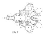
図1に概略的に示されるのは、双発ターボファン航空機ガスタービンエンジン10、並びに航空機燃料11を貯蔵するための内部燃料タンク4及び2つのウェットウィング燃料タンク6を有する例示的なガスタービンエンジンを動力源とした航空機2である。ウィング燃料タンク6は、翼内に収容されて、航空機が通過して飛行する周囲空気の冷却及び加熱に曝される理由から湿潤していると見なされる。航空機は、ガスタービンエンジン10の一方又は両方により動力が供給される適応出力熱管理システム(APTMS)12を含む。
Shown schematically in FIG. 1 is an exemplary gas turbine engine having a twin turbofan aircraft
図1及び2を参照すると、適応出力熱管理システム(APTMS)12は、液体及び空気冷却される航空機構成要素16及び機器を冷却し、並びにコックピット18の熱制御及び加圧を行う環境制御システム(ECS)14を含む。例示的な冷却航空機構成要素16は、指向性エネルギー兵器(DEW)20、航空機電子機器22、交流(AC)電子機器24、機上不活性ガス発生システム(OBIGGS)26、及び機上酸素ガス発生システム(OBOGS)28を含む。
Referring to FIGS. 1 and 2, an adaptive output thermal management system (APTMS) 12 cools liquid and air cooled
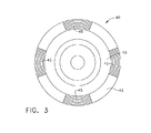
環境制御システム(ECS)14は、空気サイクルシステムACS27及び蒸気サイクルシステム(VCS)29によって冷却される。ACS27は、可変速度空気サイクル機械(ACM)34と、空気−空気ダクト熱交換器40を含む中間冷却器36とを含む。例示的なダクト熱交換器40は、エンジン10のFLADEダクト42内に配置され、図3に示すようなFLADEダクト42の周りに配置された熱交換器セクション45を含むことができる。ダクト熱交換器40は、図2に示すエンジンのファンバイパスダクト43のようなファンダクトの別のタイプに配置することができる。
The environmental control system (ECS) 14 is cooled by an air cycle system ACS 27 and a steam cycle system (VCS) 29. The ACS 27 includes an variable speed air cycle machine (ACM) 34 and an
中間冷却器36を用いて、ACM34によって冷却される冷却空気46を冷却する。中間冷却器36は更に、航空機ガスタービンエンジン10の燃料に使用されるエンジン燃焼燃料38と熱連通したエンジン燃焼燃料−空気熱交換器44を含む。中間冷却器36の下流側にあるエンジン燃焼燃料−空気熱交換器44は、ポリアルファオレフィン(PAO)ループ48を用いて、ACM34からの冷却空気46とエンジン燃焼燃料38との間で熱交換を行う。
The
ダクト熱交換器40及び燃料−空気熱交換器44はインラインであり、機械圧縮機50とACM34の冷却タービン52との間に流れる冷却空気46を冷却するのに使用される。冷却空気46は、機械圧縮機50から中間冷却器36を通って冷却タービン52に送られる。次に、冷却タービン52から出た冷却空気46は、内部燃料タンク4を冷却するのに使用される。ACM34は、シャフト56を介して機械圧縮機50及び冷却タービン52を駆動するためのACM出力タービン54を含む。ACM出力タービン54は、航空機ガスタービンエンジン10のうちの1つの高圧圧縮機64の圧縮機吐出段60からの加圧空気58により動力が供給される。
The
圧縮機吐出段60からの加圧空気58は、CDP空気又はブリードと呼ばれることが多い。CDPは、圧縮機吐出圧の頭文字として公知である。圧縮機吐出段60からの加圧空気58は、出力タービン54の出力タービン入口102に流入する。出力タービン54に流入する加圧空気58の流量及び圧力は、圧縮機吐出段60と出力タービン54の出力タービン入口102との間に配置されたCDP圧力レギュレータ104により調節される。
The
本明細書で示される例示的な出力タービン54は、固定区域出力タービン入口ノズル68を有するが、可変区域入口ノズルであってもよい。可変区域入口ノズルは、より複雑であるが、CDP圧力レギュレータに関連する圧力損失なしでタービン流を変化させ、タービン速度を設定する。
The
ACM冷却圧縮機50の出力要件が、加圧空気58のエネルギーだけを用いた冷却タービン52により利用可能な出力を上回る場合には、圧縮機吐出段60からの加圧空気58をACM燃焼器62において加熱し、ACM出力タービン54により生成される出力を増大させるようにする。ACM燃焼器62は、CDP圧力レギュレータ104と出力タービン54への出力タービン入口との間に配置される。適応出力熱管理システム(APTMS)12の例示的な実施形態において、比較的小さなACM燃焼器62は、加圧空気58を約1450°Fまで加熱する。ACM出力タービン54から排出される加圧空気58は、ガスタービン排気ノズル59のスロート57の上流側にあるエンジン排気口84に放出され、出力タービン空気流から推力を回収する。
If the output requirements of the
本明細書で示される例示的なACM34は、圧縮機入口72及び圧縮機出口73を有する遠心機械圧縮機50と、冷却タービン入口74及び冷却タービン出口75を有する半径方向流入冷却タービン52と、半径方向流入又は軸方向ACM出力タービン54とを含む。本明細書で示される例示的な冷却タービン52は、固定区域冷却タービン入口ノズル68を有するが、失速マージンに対する作動ライン上で機械圧縮機を維持するような可変ノズルであってもよい。
The
内部燃料タンク4からの冷却燃料21は、燃料再循環ループ66の配管23を通って空気サイクルシステム熱交換器30に、次いで、蒸気サイクルシステム(VCS)29のVCS凝縮器32に流れ、ここでVCS29における作動流体80を冷却するのに使用される。作動流体80は、R−134aのような公知の冷媒とすることができる。VCS29は更に、VCS圧縮機81及びVCS蒸発器82を含む。作動流体80は、VCS凝縮器32からVCS圧縮機81、及び航空機構成要素16(直接エネルギー兵器、液圧、及び空気システムを含む)を冷却するVCS蒸発器82に、次いでVCS凝縮器32に戻る冷却ループ83にて再循環される。凝縮器はまた、VCS熱交換器87である点に留意されたい。
The cooled
ACM34の冷却タービン52から排出される冷却空気46は、空気サイクルシステム熱交換器30に送られ、これを用いて燃料再循環ループ66における冷却燃料21を冷却する。冷却空気46は、空気サイクルシステム熱交換器30から機械圧縮機50へのACS圧縮機入口72に流れる。機械圧縮機50へのACS圧縮機入口72は、中段圧力レギュレータ78によりエンジン中段ブリード76に関連付けられる。中段圧力レギュレータ78は、ACM冷却空気ループ106を充填し、且つ機械圧縮機50へのACS圧縮機入口72にて可変圧力を維持するのに使用される。ACM冷却空気ループ106は、機械圧縮機50、冷却タービン52、FLADE空気熱交換器40及びエンジン燃料−空気熱交換器44を含む中間冷却器36、並びに空気サイクルシステム熱交換器30を含む。
The cooling
冷却燃料21は、VCS凝縮器32から内部燃料タンク4に戻り、従って、オンデマンドヒートシンクとして作動できる内部燃料タンク4において燃料を冷却する。配管23を通る流量は、例えば200gpmのように極めて高く設計され、ACS又はVCSにおいて大きな温度勾配がないようにする。しかしながら、この燃料再循環のためのポンプ出力は、約18HPほどの大きさにすぎない。従って、適応出力熱管理システムAPTMS12は、必要に応じて、例えばDEW20などのオンデマンド冷却として使用するために、内部燃料タンク4の燃料を冷却するのに使用される。
The cooled
ACM34とエンジン燃焼燃料との間の熱伝達は、PAOループ48を介して、ACM34からの冷却空気46とエンジン燃焼燃料38との間の熱交換に使用される。本明細書で示されるACS27において、ACS中間冷却用の熱伝達は、エンジン燃焼燃料に熱を伝達する他の航空機システムとは別個に処理される。ACSによる冷却後、低温の再循環ループ燃料がVCS凝縮器に流れる。VCSは、R−134a冷媒を使用し、全航空機電子機器に対して一定の59°F流体温度を提供する。PAOループは、VCSに対する1つの選択肢として用いることができる。
Heat transfer between the
適応出力熱管理システム(APTMS)12は、空気冷却回路88、燃料冷却回路90、及び冷媒冷却回路92を含むものとして説明することができる。空気冷却回路88は、機械圧縮機50、冷却タービン52、及び中間冷却器36を含む。中間冷却器36は、機械圧縮機出口73と冷却タービン入口74との間に配置される。空気冷却回路88は更に、冷却タービン出口75と機械圧縮機入口72との間で直列空気流れ関係で空気サイクルシステム熱交換器30を含む。燃料冷却回路90は、空気サイクルシステム熱交換器30を含む燃料再循環ループ66であり、燃料再循環ループ66において冷却燃料21を冷却するのに使用される。空気サイクルシステム熱交換器30は、空気冷却回路88と燃料冷却回路90との間の空気−燃料熱交換器である。
The adaptive output thermal management system (APTMS) 12 can be described as including an
ACS冷却能力に対する最も大きな影響は、機械圧縮機50を通る冷却空気46の圧力比と空気流量である。また、圧力比が大きくなると、冷却タービン52にわたる冷却速度が高くなる。また、流量が大きくなると、ファン空気ダクト熱交換器40及びエンジン燃料−空気熱交換器44と、VCS29において蒸気サイクルシステム(VCS)凝縮器32を冷却する燃料再循環ループ66の空気サイクルシステム熱交換器30との両方における冷却速度が増大する。高い圧縮機圧力比及び流量は通常、圧縮機吐出段60からのような、航空機ガスタービンエンジン10の一方の高圧圧縮機64からより多くの出力を必要とすることになる。これは、高CDPブリードによるエンジンSFCに悪影響を及ぼす。
The greatest influence on the ACS cooling capacity is the pressure ratio of the cooling
本明細書で開示される適応出力熱管理システムAPTMS12は、ACS冷却のオンデマンドデュアルモードを用いることによりこの問題に対処する。高い冷却速度が必要とされない場合、ACMは、冷却空気46の低圧力比及び対応する低流量を生じる。APTMS出力モードは、ACM機械圧縮機50の圧力比により定義される。所与の望ましい圧力比において、冷却タービン入口ノズル68がチョークされることに起因して、該ノズルは物理的な流れを設定する。これは、ノズル流動係数、タービン圧力比、及びタービン修正速度に応じたものである。最適効率及び十分な失速マージンを得るために選ばれた作動ライン上に圧縮機を維持するよう圧縮機修正速度が変更される。
The adaptive output thermal
例示的な高出力修正速度は、圧力比6.0に相当し、対応する例示的な低出力修正速度は、圧力比3.0に相当する。これらの値は、どの航空機飛行点又はエンジン出力設定においても本質的に一定のままである。ACM34のシャフト物理速度、圧縮機入口温度、及び圧縮機入口圧力の検知した値に関して、電子ACMエンジン制御装置70を用いて、中段圧力レギュレータ78のような流量調整バルブを用いてACM出力タービン54への圧力を調整することにより修正速度を電気的に制御することは公知である。ACM機械圧縮機50に流入する圧縮機吐出段60からの加圧空気58の例示的な圧力は、約10psigである。
An exemplary high power correction speed corresponds to a pressure ratio of 6.0, and a corresponding exemplary low power correction speed corresponds to a pressure ratio of 3.0. These values remain essentially constant at any aircraft flight point or engine power setting. With respect to the sensed values of the
ACMエンジン制御装置70が航空機飛行制御装置からの命令を受け取るときに、オンデマンド冷却が提供される。ACMエンジン制御装置70はまた、CDP圧力レギュレータ104を制御し、出力タービン54に流入する加圧空気58の流量及び圧力を制御する。また、ACMエンジン制御装置70を用いて、ACM燃焼器62を制御することができる。ACMエンジン制御装置70は、内部燃料タンク4のヒートシンク能力を増大させ、出力タービン54に流入する加圧空気58の流量及び圧力を増大させることによりオンデマンド冷却を提供することができる。
On-demand cooling is provided when the ACM engine controller 70 receives instructions from the aircraft flight controller. The ACM engine controller 70 also controls the
FLADEダクト42は、ファン段よりも通常はFLADE段の方がより少なく、よってFLADEダクト空気流の方がより低温であるので、ダクト熱交換器40にとって良好な場所にある。FLADEエンジン(FLADEは、「ファンオンブレード」の頭文字である)は、FLADEダクト42にわたって半径方向に延びて半径方向内側ファン7に接続され、すなわち半径方向内側ファン7により駆動されるFLADEファンブレード5を有する外側ファン3により特徴付けられる。外側ファン3は、FLADE空気をFLADEダクト42に吐出し、該FLADEダクト42は、内側ファン7を囲む半径方向内側ファンダクト9をほぼ同心環状で囲む。Thomas他による「Two Spool Variable Cycle Engine」の名称の米国特許第4,043,121号において開示されている1つのこのようなエンジンは、FLADEファンと外側ファンダクトとを備え、該外側ファンダクト内で、可変ガイドベーンがFLADE外側ファンダクトを通過する空気の量を制御することによってサイクル変動を制御している。FLADEエンジンは、高度及び飛行マッハ数のような亜音速飛行周囲条件の所定のセットにおける比較的広い推力範囲にわたって本質的に一定の入口空気流量を維持してスピレージ抗力を回避し、また飛行条件の範囲全体にわたってそのようにすることができることが研究されてきた。この性能は、特に亜音速部分出力エンジン運転状態にとって必要とされる。これらの実施例は、「Spillage Drag and Infrared Reducing FLADE Engine」の名称の米国特許第5,404,713号において開示されている。
The
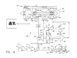
内部燃料タンク4における追加の冷却は、図4に示すように、2つのウェットウィング燃料タンク6が内部燃料タンク4よりも十分に低温である場合に、該ウェットウィング燃料タンク6により提供することができる。ウェットウィング燃料タンク6は、航空機が亜音速運転中に周囲空気を通過して飛行するときに冷却に曝される。内部燃料タンク再循環ループ110は、ウィング燃料タンクと内部燃料タンクとの間で燃料を再循環させるのに用いることができる。内部燃料タンク再循環ループ110は、亜音速飛行中に遮断することができ、燃料再循環ループ66において燃料を冷却するため内部燃料タンク4に追加のヒートシンク能力を提供する。追加のヒートシンク能力は、航空機構成要素16を冷却するために追加の冷却能力を冷却蒸気サイクルシステム29が利用できるようにする。電子ACMエンジン制御装置70を用いて、内部燃料タンク再循環ループ110における燃料の流量を制御し、並びにその作動又は遮断を行うことができる。
Additional cooling in the
図4はまた、ACM出力タービン54に動力を供給するための高圧圧縮機64の中段112から抽気される加圧空気58を示している。中段112は、高圧圧縮機64の第1段113と圧縮機吐出段60の間のほぼ2分の1のところにある。冷却タービン52から流出する冷却空気46の冷却空気部分118は、コックピット18、航空機電子機器22、機上不活性ガス発生システム(OBIGGS)26、及び機上酸素ガス発生システム(OBOGS)28のうちの少なくとも1つの冷却及び通気のために用いることができる。
FIG. 4 also shows the
適応出力熱管理システム(APTMS)12は、従来のヒートシンク(ラム空気、ファン空気、FLADE空気、及び/又はエンジン燃焼燃料)への、並びに航空機燃料タンクヒートシンク又は航空機燃料タンクに貯蔵された燃料への必要熱負荷の定常状態伝達を提供する。DEW発射のようなクリティカルミッションポイントで必要とされる高レベルの冷却を得るために、APTMSは、便宜的ミッションセグメント中に高い冷却出力で作動しなければならない。便宜的ミッションセグメントの間、APTMS12ヒートシンク又は冷却能力は、クリティカルミッションポイント又はセグメント中に後で使用するために燃料タンク内に構成又は格納される。
The adaptive power thermal management system (APTMS) 12 is directed to conventional heat sinks (ram air, fan air, FLADE air, and / or engine combustion fuel) and to fuel stored in an aircraft fuel tank heat sink or aircraft fuel tank. Provides steady state transmission of required heat load. In order to obtain the high level of cooling required at critical mission points such as DEW launches, APTMS must operate at a high cooling power during a convenient mission segment. During the convenience mission segment, the
燃料タンクヒートシンク又は冷却能力を構成するための2つの例示的な便宜的ミッションセグメントは、離陸前のグランドアイドル(通常は20分継続)及び巡航高度までの初期上昇中(通常は3〜5分継続)にある。これらの便宜的ミッションセグメントの間は、APTMSは最大冷却出力で運転されることになる。ラム空気、ファン空気、又はFLADE空気ヒートシンクの温度に応じて、APTMSは、DEW発射のようなクリティカルミッションポイント中に最大冷却出力で作動する場合もあり、又は作動しない場合もある。他のミッションポイントでは、APTMSは、クリティカル冷却又はタンク冷却において必要性がないので低冷却出力で運転され、従って、燃料が節減される。 Two exemplary expedient mission segments for configuring a fuel tank heat sink or cooling capacity are ground idle before takeoff (usually lasts 20 minutes) and during initial climb to cruising altitude (usually 3-5 minutes) )It is in. During these expedient mission segments, the APTMS will be operated at maximum cooling power. Depending on the temperature of the ram air, fan air, or FLADE air heat sink, the APTMS may or may not operate at maximum cooling power during critical mission points such as DEW launch. At other mission points, APTMS is operated at low cooling power because there is no need for critical cooling or tank cooling, thus saving fuel.
ACM出力タービン54は、航空機ガスタービンエンジン10の高圧圧縮機64の圧縮機吐出段60からの加圧空気58又はブリード空気により動力が供給される。燃料節減は、APTMS12がミッション全体にわたって最大冷却出力で運転する必要がないことによって得られ、全時間にわたり圧縮機ブリード空気を使用することに対するSFCの不利条件は極めて好ましくない。この過剰SFCに加えて、過剰なエンジンコア抽気に関する懸念もあり、高い燃空比及び高エンジンタービン入口温度を生じる可能性がある。エンジンコア抽気に関する例示的な望ましい限度は通常、コア入口流の10%である。
The
従って、本発明の重要な態様は、APTMS冷却出力及びAPTMS冷却出力を制御する手段である。電子ACMエンジン制御装置70は、航空機飛行制御装置からAPTMS冷却出力セットポイント信号を受け取るよう作動する。例えば、ACM冷却出力需要は、コアブリードの10%を超えること無く最大燃料タンク冷却速度を達成するためにグランドアイドル中に95%とすることができる。 Thus, an important aspect of the present invention is a means for controlling the APTMS cooling power and the APTMS cooling power. The electronic ACM engine controller 70 is operative to receive the APTMS cooling power setpoint signal from the aircraft flight controller. For example, the ACM cooling power demand can be 95% during ground idle to achieve the maximum fuel tank cooling rate without exceeding 10% of the core bleed.
冷却出力は、パーセントACM修正シャフト速度(%RPM)を用いて表され、(RPM/平方根(θ))である。ここで、θ=圧縮機入口温度/518.7Rであり、RPMはシャフト56の測定シャフト速度である。圧縮機入口温度は、機械圧縮機50の機械圧縮機入口72の温度であり、シャフトはACM34のシャフト56である。電子ACMエンジン制御装置70は、圧縮機作動ライン修正流量及び圧縮機圧力比の値をパーセント修正速度の各値に割り当て、そのECメモリ内に記憶する。電子ACMエンジン制御装置70は、ACMシャフト56物理的速度、圧縮機入口温度、及び圧縮機入口圧力の検知値を表す信号を受け取る。
The cooling power is expressed using percent ACM corrected shaft speed (% RPM) and is (RPM / square root (θ)). Where θ = compressor inlet temperature / 518.7R and RPM is the measured shaft speed of shaft 56. The compressor inlet temperature is the temperature of the
圧縮機物理的流量は、例示的な冷却タービン52のACM冷却タービン入口ノズル68により決定される。電子ACMエンジン制御装置70は、ACM冷却タービン入口ノズル68の冷却タービン入口温度及び入口圧力の検知値を受け取る。これらの値並びに
シャフト速度及び固定タービンノズル吐出区域により、電子ACMエンジン制御装置70は、タービンノズル物理流量を計算できるようになり、該タービンノズル物理流量は、本明細書で示される閉ループにおいて、機械圧縮機50の機械圧縮機入口72の圧縮機入口物理流量と同じである。
The compressor physical flow is determined by the ACM cooling
電子ACMエンジン制御装置70は、機械圧縮機50の物理的流量からの圧縮機の実修正流量(W X 平方根θ/Δ)、圧縮機入口圧力、及び圧縮機入口温度を計算する。Wは、本明細書で示され且つ上記で説明された閉ループにおいて、機械圧縮機50の機械圧縮機入口72の圧縮機入口物理流量と同じである、物理流量(pps)に等しい。実修正流量は、作動ライン修正流量と比較され、最大効率及び失速マージンを確保する。実修正流量が作動ラインの左側に(失速側に)移動した場合、機械圧縮機50の機械圧縮機入口72における圧力であるACM入口圧力が低下し、修正流量の増大及び作動ラインへの復帰を引き起こすようになる。
The electronic ACM engine controller 70 calculates the actual corrected flow rate of the compressor (W X square root θ / Δ), the compressor inlet pressure, and the compressor inlet temperature from the physical flow rate of the
ACM34の速度は、出力タービン54によって制御され、出力タービン入口温度は、出力タービンの上流側のACM燃焼器62により固定される。例示的な固定出力タービン入口温度は、約1450°Fである。出力タービン流量は、本明細書では圧縮機吐出段60と出力タービン54の出力タービン入口102との間に配置されたCDP圧力レギュレータ104として示されるタービンの上流側の制御バルブを開閉することによって調整される。機械圧縮機50、冷却タービン52、及び出力タービン54間の結果として得られる出力平衡によりACM物理速度が確立される。
The speed of the
本明細書では本発明の好ましく例示的な実施形態であると考えられるものについて説明してきたが、当業者であれば、本明細書の教示から本発明の他の修正が明らかになる筈であり、従って、全てのこのような修正は、本発明の技術思想及び技術的内に属するものとして特許請求の範囲において保護されることが望まれる。従って、本特許により保護されることを望むものは,特許請求の範囲に記載しかつ特定した発明である。 While this specification has described what are considered to be the preferred exemplary embodiments of the present invention, other modifications of the present invention should become apparent to those skilled in the art from the teachings herein. Accordingly, all such modifications are desired to be protected within the scope of the following claims as falling within the spirit and scope of the invention. Accordingly, what is desired to be secured by Letters Patent is the invention as defined and specified in the following claims.
2 ガスタービンエンジンを動力源とした航空機
3 外側ファン
4 燃料タンク
5 FLADEファンブレード
6 ウェットウィング燃料タンク
7 内側ファン
9 内側ファンダクト
10 ガスタービンエンジン
12 適応出力熱管理システム(APTMS)
11 航空機燃料
14 環境制御システム(ECS)
16 航空機構成要素
18 コックピット
20 指向性エネルギー兵器(DEW)
21 冷却燃料
22 航空機電子機器
23 配管
24 交流(AC)電子機器
26 機上不活性ガス発生システム(OBIGGS)
27 空気サイクルシステム(ACS)
28 機上酸素ガス発生システム(OBOGS)
29 蒸気サイクルシステム(VCS)
30 空気サイクルシステム熱交換器
32 蒸気サイクルシステム凝縮器
34 空気サイクル機械
36 中間冷却器
38 エンジン燃焼燃料
40 ダクト熱交換器
42 FLADEダクト
43 ファンバイパスダクト
44 空気熱交換器
45 熱交換器セクション
46 冷却空気
48 PAOループ
50 機械圧縮機
52 冷却タービン
54 出力ガスタービン
56 シャフト
57 スロート
58 加圧空気
59 排気ノズル
60 圧縮機吐出段
62 燃焼器
64 高圧圧縮機
66 燃料再循環ループ
68 タービン入口ノズル
70 エンジン制御装置
72 圧縮機入口
73 圧縮機出口
74 冷却タービン入口
75 冷却タービン出口
76 中段抽気
78 中段圧力レギュレータ
80 作動流体
81 VCS圧縮機
82 VCS蒸発器
83 冷却ループ
84 エンジン排気口
87 熱交換器
88 空気冷却回路
90 燃料冷却回路
92 冷媒冷却回路
102 出力タービン入口
104 圧力レギュレータ
106 空気ループ
110 中間燃料タンク再循環ループ
112 中段
113 第1段
118 冷却空気部分
2 Aircraft 3 powered by gas turbine
11
16
21
27 Air Cycle System (ACS)
28 On-machine oxygen gas generation system (OBOGS)
29 Steam cycle system (VCS)
30 Air Cycle
Claims (8)
可変冷却出力空気サイクルシステム(27)、蒸気サイクルシステム(29)、及びこれらの間に配置される燃料再循環ループ(66)と、
前記空気サイクルシステム(27)と前記燃料再循環ループ(66)との間に動作可能に配置され、前記燃料再循環ループ(66)から空気サイクルシステム(27)に熱を伝達するための空気サイクルシステム熱交換器(30)と、
前記空気サイクルシステム(27)に備えられた中間冷却器(36)と
を含み、
前記中間冷却器(36)は、FLADEダクト(42)に配置されたダクト熱交換器(40)を含み、
前記空気サイクルシステム熱交換器(30)は、前記燃料再循環ループ(66)の燃料を冷却するためだけに用いられる前記空気サイクルシステム(27)の冷却空気ループに動作可能に配置され、
前記航空機適応出力熱管理システム(12)は、更に、前記蒸気サイクルシステム(29)から前記燃料再循環ループ(66)に熱を伝達するために前記蒸気サイクルシステム(29)と前記燃料再循環ループ(66)との間に動作可能に配置される蒸気サイクル熱交換器(87)を備え、
前記空気サイクルシステム(27)が更に可変速度空気サイクル機械(34)を含み、該可変速度空気サイクル機械(34)が、機械圧縮機(50)及び前記空気サイクル機械(34)の冷却タービン(52)に駆動可能に接続された出力タービン(54)を有し、
前記中間冷却器(36)が、前記機械圧縮機(50)と前記冷却タービン(52)との間に動作可能に配置され、
前記空気サイクルシステム熱交換器(30)が、前記機械圧縮機(50)と前記冷却タービン(52)との間に動作可能に配置され、
前記出力タービン(54)が、航空機ガスタービンエンジン高圧圧縮機(64)の圧縮機段(60)から加圧空気(58)を受け入れるよう該圧縮機段(60)に接続され、
前記航空機適応出力熱管理システム(12)は、更に、 前記燃料再循環ループ(66)における1つ又はそれ以上の航空機燃料タンク(4)を備える、
システム(12)。
An aircraft adaptive output thermal management system (12),
A variable cooling output air cycle system (27), a steam cycle system (29), and a fuel recirculation loop (66) disposed therebetween;
An air cycle operatively disposed between the air cycle system (27) and the fuel recirculation loop (66) for transferring heat from the fuel recirculation loop (66) to the air cycle system (27). A system heat exchanger (30);
An intercooler (36) provided in the air cycle system (27),
The intercooler (36) includes a duct heat exchanger (40) disposed in the FLADE duct (42) ,
The air cycle system heat exchanger (30) is operably disposed in a cooling air loop of the air cycle system (27) that is used only to cool fuel in the fuel recirculation loop (66);
The aircraft adaptive output thermal management system (12) further includes the steam cycle system (29) and the fuel recirculation loop to transfer heat from the steam cycle system (29) to the fuel recirculation loop (66). A steam cycle heat exchanger (87) operatively disposed between (66) and
The air cycle system (27) further includes a variable speed air cycle machine (34), the variable speed air cycle machine (34) comprising a mechanical compressor (50) and a cooling turbine (52) of the air cycle machine (34). A power turbine (54) drivably connected to
The intercooler (36) is operatively disposed between the mechanical compressor (50) and the cooling turbine (52);
The air cycle system heat exchanger (30) is operatively disposed between the mechanical compressor (50) and the cooling turbine (52);
It said power turbine (54) is connected from an aircraft gas turbine engine compressors stage high pressure compressor (64) (60) in so that the compressor stage receiving pressurized air (58) (60),
The aircraft adaptive output thermal management system (12) further comprises one or more aircraft fuel tanks (4) in the fuel recirculation loop (66).
System (12).
空気サイクル機械(34)の冷却タービン(52)に結合された機械圧縮機(50)を含む空気冷却回路(88)を備え、
前記空気冷却回路(88)が更に、前記機械圧縮機(50)の機械圧縮機出口(73)と前記冷却タービン(52)の冷却タービン入口(74)との間に配置された中間冷却器(36)を含み、前記空気冷却回路(88)が更に、前記冷却タービン(52)の冷却タービン出口(75)と、前記機械圧縮機(50)の機械圧縮機入り口(72)との間で直列流れ関係で空気サイクル熱交換器(30)を含み、
前記航空機適応出力熱管理システム(12)が更に、1つ又はそれ以上の航空機燃料タンク(4)、前記空気サイクルシステム熱交換器(30)、及び蒸気サイクルシステム凝縮器(32)間で直列燃料流れ関係で冷却燃料(21)を再循環する燃料再循環ループ(66)を備え、
前記空気サイクルシステム熱交換器(30)は、前記燃料再循環ループ(66)の燃料を冷却するためだけに用いられる前記空気サイクルシステム(27)の冷却空気ループに動作可能に配置され、
前記空気サイクルシステム熱交換器(30)が前記1つ又はそれ以上の燃料タンク(4)と前記蒸気サイクルシステム凝縮器(32)との間で前記燃料再循環ループ(66)内に動作可能に配置され、
前記航空機適応出力熱管理システム(12)が更に、
航空機構成要素(16)に冷却を提供し、且つ直列流れ関係で前記蒸気サイクルシステム凝縮器(32)、蒸気サイクルシステム圧縮機(81)、及び蒸気サイクルシステム蒸発器(82)を含む冷却ループ(83)と、
を備え、前記中間冷却器(36)が航空機ガスタービンエンジンFLADEダクト(42)内に配置されたダクト熱交換器(40)を含み、
前記航空機適応出力熱管理システム(12)が更に、
前記中間冷却器(36)において、前記ダクト熱交換器(40)と前記冷却タービン(52)の冷却タービン入口(74)との間に配置されたエンジン燃焼燃料空気熱交換器(44)と、
前記出力タービン(54)と前記圧縮機段(60)との間に動作可能に配置された燃焼器(62)と、
を備える、航空機適応出力熱管理システム(12)。 An aircraft adaptive output thermal management system (12),
An air cooling circuit (88) comprising a mechanical compressor (50) coupled to a cooling turbine (52) of an air cycle machine (34);
The intercooler (88) further includes an air cooling circuit (88) disposed between a mechanical compressor outlet (73) of the mechanical compressor (50) and a cooling turbine inlet (74) of the cooling turbine (52). 36), wherein the air cooling circuit (88) is further in series between a cooling turbine outlet (75) of the cooling turbine (52) and a mechanical compressor inlet (72) of the mechanical compressor (50). Including an air cycle heat exchanger (30) in flow relation;
The aircraft adaptive output thermal management system (12) further includes a series fuel between one or more aircraft fuel tanks (4), the air cycle system heat exchanger (30), and the steam cycle system condenser (32). A fuel recirculation loop (66) for recirculating cooling fuel (21) in a flow relationship;
The air cycle system heat exchanger (30) is operably disposed in a cooling air loop of the air cycle system (27) that is used only to cool fuel in the fuel recirculation loop (66);
The air cycle system heat exchanger (30) is operable in the fuel recirculation loop (66) between the one or more fuel tanks (4) and the vapor cycle system condenser (32). Arranged,
The aircraft adaptive output thermal management system (12) further comprises:
A cooling loop that provides cooling to the aircraft component (16) and includes the steam cycle system condenser (32), the steam cycle system compressor (81), and the steam cycle system evaporator (82) in a serial flow relationship ( 83)
Said intercooler (36) includes a duct heat exchanger (40) disposed in an aircraft gas turbine engine FLADE duct (42);
The aircraft adaptive output thermal management system (12) further comprises:
An engine combustion fuel air heat exchanger (44) disposed between the duct heat exchanger (40) and a cooling turbine inlet (74) of the cooling turbine (52) in the intercooler (36);
A combustor (62) operatively disposed between the power turbine (54) and the compressor stage (60);
An aircraft adaptive output thermal management system (12) comprising:
The mechanical compressor (50) and is drivingly connected the cooling turbine (52), Ru receiving pressurized air (58) from the compressors discharge stage (60) of the aircraft gas turbine engine high pressure compressor (64) The aircraft adaptive output thermal management system (12) of claim 7, further comprising a power turbine (54) connected to the compressor discharge stage (60 ).
Applications Claiming Priority (2)
| Application Number | Priority Date | Filing Date | Title |
|---|---|---|---|
| US13/117,627 US8522572B2 (en) | 2010-07-01 | 2011-05-27 | Adaptive power and thermal management system |
| US13/117,627 | 2011-05-27 |
Publications (3)
| Publication Number | Publication Date |
|---|---|
| JP2012246928A JP2012246928A (en) | 2012-12-13 |
| JP2012246928A5 JP2012246928A5 (en) | 2015-07-09 |
| JP5976397B2 true JP5976397B2 (en) | 2016-08-23 |
Family
ID=46168268
Family Applications (1)
| Application Number | Title | Priority Date | Filing Date |
|---|---|---|---|
| JP2012119289A Expired - Fee Related JP5976397B2 (en) | 2011-05-27 | 2012-05-25 | Adaptive output thermal management system |
Country Status (3)
| Country | Link |
|---|---|
| EP (1) | EP2527252A3 (en) |
| JP (1) | JP5976397B2 (en) |
| CA (1) | CA2777997A1 (en) |
Cited By (1)
| Publication number | Priority date | Publication date | Assignee | Title |
|---|---|---|---|---|
| CN109611212A (en) * | 2018-12-10 | 2019-04-12 | 中国航发四川燃气涡轮研究院 | It is a kind of with hot oil case can oil return aero-engine heat management system |
Families Citing this family (17)
| Publication number | Priority date | Publication date | Assignee | Title |
|---|---|---|---|---|
| CN104141527B (en) * | 2014-07-02 | 2017-07-21 | 北京航空航天大学 | Heat-exchange method between a kind of turbocharger stage |
| US9657648B2 (en) * | 2014-11-25 | 2017-05-23 | Hamilton Sundstrand Corporation | Environmental air conditioning system |
| US9828870B2 (en) | 2015-06-11 | 2017-11-28 | Northrop Grumman Systems Corporation | Efficient power and thermal management system for high performance aircraft |
| US10239624B2 (en) * | 2017-02-15 | 2019-03-26 | The Boeing Company | Reverse air cycle machine (RACM) thermal management systems and methods |
| US10584903B2 (en) * | 2017-03-06 | 2020-03-10 | Rocky Research | Intelligent cooling system |
| US10584944B2 (en) | 2017-03-06 | 2020-03-10 | Rocky Research | Burst mode cooling system |
| US11692779B2 (en) | 2020-01-23 | 2023-07-04 | Rocky Research | Flexible cooling system with thermal energy storage |
| US20220242582A1 (en) | 2021-02-01 | 2022-08-04 | General Electric Company | Vehicle and propulsion system with gaseous fuel system |
| CN113153537B (en) * | 2021-03-19 | 2022-05-17 | 哈尔滨工业大学 | A three-wheel cooling-refrigeration cycle cooling system for hypersonic aircraft |
| CN114151137B (en) * | 2021-10-20 | 2023-09-05 | 中国航发四川燃气涡轮研究院 | Combined cooling thermal management system for high Mach number aeroengine cabin and turbine disk |
| GB2622208A (en) | 2022-09-06 | 2024-03-13 | Rolls Royce Plc | A thermal management system for an aircraft |
| GB2622212B (en) | 2022-09-06 | 2024-11-20 | Rolls Royce Plc | A thermal management system for an aircraft |
| GB2622215B (en) | 2022-09-06 | 2024-12-04 | Rolls Royce Plc | A thermal management system for an aircraft |
| GB2622209B (en) | 2022-09-06 | 2024-12-04 | Rolls Royce Plc | A thermal management system for an aircraft |
| GB2622211A (en) | 2022-09-06 | 2024-03-13 | Rolls Royce Plc | A thermal management system for an aircraft |
| GB2622214A (en) | 2022-09-06 | 2024-03-13 | Rolls Royce Plc | A thermal management system for an aircraft |
| CN115583349B (en) * | 2022-12-13 | 2023-04-18 | 中国民用航空飞行学院 | Aircraft self-adaptation emergency system based on meteorological big data |
Family Cites Families (23)
| Publication number | Priority date | Publication date | Assignee | Title |
|---|---|---|---|---|
| US4043121A (en) | 1975-01-02 | 1977-08-23 | General Electric Company | Two-spool variable cycle engine |
| US4503666A (en) | 1983-05-16 | 1985-03-12 | Rockwell International Corporation | Aircraft environmental control system with auxiliary power output |
| US4494372A (en) | 1983-06-10 | 1985-01-22 | Lockheed Corporation | Multi role primary/auxiliary power system with engine start capability for aircraft |
| US4684081A (en) | 1986-06-11 | 1987-08-04 | Lockheed Corporation | Multifunction power system for an aircraft |
| US5404713A (en) * | 1993-10-04 | 1995-04-11 | General Electric Company | Spillage drag and infrared reducing flade engine |
| US5490645A (en) | 1993-12-09 | 1996-02-13 | Allied-Signal Inc. | Fully integrated environmental and secondary power system |
| US5442905A (en) | 1994-04-08 | 1995-08-22 | Alliedsignal Inc. | Integrated power and cooling environmental control system |
| US6182435B1 (en) * | 1997-06-05 | 2001-02-06 | Hamilton Sundstrand Corporation | Thermal and energy management method and apparatus for an aircraft |
| US5899085A (en) * | 1997-08-01 | 1999-05-04 | Mcdonnell Douglas Corporation | Integrated air conditioning and power unit |
| US6415595B1 (en) * | 2000-08-22 | 2002-07-09 | Hamilton Sundstrand Corporation | Integrated thermal management and coolant system for an aircraft |
| US6845630B2 (en) | 2001-02-16 | 2005-01-25 | Hamilton Sundstrand Corporation | Electric power and cooling system for an aircraft |
| US6948331B1 (en) * | 2003-09-12 | 2005-09-27 | Norhrop Grumman Corporation | Environmental control system for an aircraft |
| FR2864996B1 (en) * | 2004-01-13 | 2006-03-10 | Snecma Moteurs | SYSTEM FOR COOLING HOT PARTS OF AN AIRCRAFT ENGINE, AND AIRCRAFT ENGINE EQUIPPED WITH SUCH A COOLING SYSTEM |
| US7624592B2 (en) * | 2006-05-17 | 2009-12-01 | Northrop Grumman Corporation | Flexible power and thermal architectures using a common machine |
| ES2325774T3 (en) * | 2006-09-25 | 2009-09-16 | Saab Ab | AVIONICA COOLING. |
| US7823389B2 (en) * | 2006-11-15 | 2010-11-02 | General Electric Company | Compound clearance control engine |
| FR2914365B1 (en) * | 2007-03-28 | 2012-05-18 | Airbus France | SYSTEM FOR COOLING AND REGULATING EQUIPMENT TEMPERATURE OF A PROPELLANT AIRCRAFT ASSEMBLY. |
| US20100170262A1 (en) * | 2009-01-06 | 2010-07-08 | Kaslusky Scott F | Aircraft power and thermal management system with electric co-generation |
| US20100313591A1 (en) * | 2009-06-12 | 2010-12-16 | Hamilton Sundstrand Corporation | Adaptive heat sink for aircraft environmental control system |
| US20110167784A1 (en) * | 2009-09-25 | 2011-07-14 | James Edward Johnson | Method of operating a convertible fan engine |
| US20110167792A1 (en) * | 2009-09-25 | 2011-07-14 | James Edward Johnson | Adaptive engine |
| US20110120083A1 (en) * | 2009-11-20 | 2011-05-26 | Rollin George Giffin | Gas turbine engine with outer fans |
| US8695324B2 (en) * | 2009-11-20 | 2014-04-15 | General Electric Co. | Multistage tip fan |
-
2012
- 2012-05-24 EP EP12169395.6A patent/EP2527252A3/en not_active Withdrawn
- 2012-05-24 CA CA2777997A patent/CA2777997A1/en not_active Abandoned
- 2012-05-25 JP JP2012119289A patent/JP5976397B2/en not_active Expired - Fee Related
Cited By (2)
| Publication number | Priority date | Publication date | Assignee | Title |
|---|---|---|---|---|
| CN109611212A (en) * | 2018-12-10 | 2019-04-12 | 中国航发四川燃气涡轮研究院 | It is a kind of with hot oil case can oil return aero-engine heat management system |
| CN109611212B (en) * | 2018-12-10 | 2021-05-04 | 中国航发四川燃气涡轮研究院 | Take aircraft engine thermal management system of hot oil tank returnable oil |
Also Published As
| Publication number | Publication date |
|---|---|
| EP2527252A3 (en) | 2018-01-10 |
| EP2527252A2 (en) | 2012-11-28 |
| JP2012246928A (en) | 2012-12-13 |
| CA2777997A1 (en) | 2012-11-27 |
Similar Documents
| Publication | Publication Date | Title |
|---|---|---|
| JP5976397B2 (en) | Adaptive output thermal management system | |
| US8522572B2 (en) | Adaptive power and thermal management system | |
| JP6165413B2 (en) | Environmental control system supply precooler bypass | |
| JP5976396B2 (en) | FLADE turbine cooling and power and thermal management | |
| US11746701B2 (en) | Bleed expander cooling with turbine | |
| US11788470B2 (en) | Gas turbine engine thermal management | |
| US8955794B2 (en) | Bleed air systems for use with aircrafts and related methods | |
| EP2829706B1 (en) | Bleed air systems for use with aircrafts and related methods | |
| EP3608228B1 (en) | Powered pre-cooler fan assembly | |
| JP2017524092A (en) | Jet engine cold air cooling system | |
| CN116464554B (en) | Exhaust flow components for gas turbine engines | |
| EP1283166B1 (en) | Conditioning of air supply | |
| US20220145796A1 (en) | Combustion engine including turbomachine | |
| CN116464555B (en) | Exhaust flow assembly for a gas turbine engine | |
| US20230228216A1 (en) | Bleed flow assembly for a gas turbine engine | |
| US20260036065A1 (en) | Passive thermal management systems and related methods | |
| US20240246693A1 (en) | Fuel cooling system | |
| US12006869B2 (en) | Heat exchanger for a gas turbine engine | |
| CN116464552B (en) | Exhaust flow components for gas turbine engines | |
| US20250354519A1 (en) | Gas turbine engine having cooling systems |
Legal Events
| Date | Code | Title | Description |
|---|---|---|---|
| A521 | Written amendment |
Free format text: JAPANESE INTERMEDIATE CODE: A523 Effective date: 20150521 |
|
| A621 | Written request for application examination |
Free format text: JAPANESE INTERMEDIATE CODE: A621 Effective date: 20150521 |
|
| A977 | Report on retrieval |
Free format text: JAPANESE INTERMEDIATE CODE: A971007 Effective date: 20160315 |
|
| A131 | Notification of reasons for refusal |
Free format text: JAPANESE INTERMEDIATE CODE: A131 Effective date: 20160322 |
|
| A521 | Written amendment |
Free format text: JAPANESE INTERMEDIATE CODE: A523 Effective date: 20160606 |
|
| TRDD | Decision of grant or rejection written | ||
| A01 | Written decision to grant a patent or to grant a registration (utility model) |
Free format text: JAPANESE INTERMEDIATE CODE: A01 Effective date: 20160705 |
|
| A61 | First payment of annual fees (during grant procedure) |
Free format text: JAPANESE INTERMEDIATE CODE: A61 Effective date: 20160720 |
|
| R150 | Certificate of patent or registration of utility model |
Ref document number: 5976397 Country of ref document: JP Free format text: JAPANESE INTERMEDIATE CODE: R150 |
|
| LAPS | Cancellation because of no payment of annual fees |