JP5976027B2 - Sensor axis deviation detection device and sensor axis deviation detection method - Google Patents
Sensor axis deviation detection device and sensor axis deviation detection method Download PDFInfo
- Publication number
- JP5976027B2 JP5976027B2 JP2014065484A JP2014065484A JP5976027B2 JP 5976027 B2 JP5976027 B2 JP 5976027B2 JP 2014065484 A JP2014065484 A JP 2014065484A JP 2014065484 A JP2014065484 A JP 2014065484A JP 5976027 B2 JP5976027 B2 JP 5976027B2
- Authority
- JP
- Japan
- Prior art keywords
- sensor
- detection
- detection target
- sensor information
- area
- Prior art date
- Legal status (The legal status is an assumption and is not a legal conclusion. Google has not performed a legal analysis and makes no representation as to the accuracy of the status listed.)
- Active
Links
- 238000001514 detection method Methods 0.000 title claims description 353
- 238000000034 method Methods 0.000 description 18
- 230000004927 fusion Effects 0.000 description 6
- 238000010586 diagram Methods 0.000 description 4
- 230000003287 optical effect Effects 0.000 description 3
- 230000000694 effects Effects 0.000 description 2
- 238000005070 sampling Methods 0.000 description 1
Images


Landscapes
- Measurement Of Optical Distance (AREA)
- Radar Systems Or Details Thereof (AREA)
- Optical Radar Systems And Details Thereof (AREA)
Description
本発明は、複数のセンサ間の軸ずれを検出するセンサ軸ずれ検出装置およびセンサ軸ずれ検出方法に関するものである。 The present invention relates to a sensor axis deviation detection device and a sensor axis deviation detection method for detecting axis deviations between a plurality of sensors.
複数のセンサからのセンサ情報を融合することで、単一センサのみではなし得ない周辺状況認識性能を達成するセンサフュージョン技術がある。そして、このようなセンサフュージョン技術においては、各センサ間の座標軸が互いにずれていると、同一の物体を別々の物体と認識してしまい、融合に失敗する。このため、複数のセンサ間での軸ずれがある場合に、このような軸ずれを補正したり、センサ情報の融合を中止したりする技術が提案されている。 There is a sensor fusion technology that achieves a surrounding situation recognition performance that cannot be achieved by a single sensor alone by fusing sensor information from a plurality of sensors. In such sensor fusion technology, if the coordinate axes between the sensors are shifted from each other, the same object is recognized as a separate object, and the fusion fails. For this reason, in the case where there is an axis misalignment between a plurality of sensors, a technique for correcting such an axis misalignment or stopping the fusion of sensor information has been proposed.
このような従来技術の一例として、複数のセンサとして車両に搭載した光学カメラおよびレーザレーダのそれぞれにおいて、検出物体の距離と速度を計測し、検出物体と自車両とが衝突するまでの時間を計算する。そして、それぞれのセンサが計算した衝突するまでの時間が一致するように、光学カメラの水平位置を補正する(例えば、特許文献1参照)。 As an example of such conventional technology, the distance and speed of the detected object are measured in each of the optical camera and laser radar mounted on the vehicle as a plurality of sensors, and the time until the detected object and the vehicle collide is calculated. To do. Then, the horizontal position of the optical camera is corrected so that the time until the collision calculated by each sensor matches (for example, refer to Patent Document 1).
このような従来技術の別例として、複数のセンサとして車両に搭載した光学カメラおよびミリ波レーダのそれぞれにおいて、検出物体の座標をそれぞれ計測し、計測した座標の複数サンプリングから方位角の軸ずれ補正量を学習する。そして、学習した軸ずれ補正量が一定値よりも大きい場合には、センサ情報の融合を中止する(例えば、特許文献2参照)。 As another example of such a prior art, the coordinates of the detected object are measured in each of the optical camera and millimeter wave radar mounted on the vehicle as a plurality of sensors, and the azimuth misalignment is corrected from multiple sampling of the measured coordinates. Learn quantity. When the learned axis deviation correction amount is larger than a certain value, the fusion of sensor information is stopped (see, for example, Patent Document 2).
また、このように複数のセンサ間での軸ずれを補正したり、センサ情報の融合を中止したりする前提としては、複数のセンサ間の軸ずれが発生した場合に、この軸ずれを正確に検出する必要がある。 In addition, in order to correct the misalignment between a plurality of sensors and to stop the fusion of sensor information in this way, when the misalignment between a plurality of sensors occurs, It needs to be detected.
しかしながら、従来技術には以下のような課題がある。
特許文献1、2に記載の従来技術においては、複数のセンサ間の軸ずれを検出する際には、複数のセンサのすべてが同一の物体を検出することが前提である。しかしながら、複数のセンサのそれぞれの検出特性(検出領域(覆域))が異なるので、これらすべてのセンサが同一の物体を検出できるとは限らない。
However, the prior art has the following problems.
In the prior arts described in Patent Documents 1 and 2, it is premised that all of the plurality of sensors detect the same object when detecting an axial deviation between the plurality of sensors. However, since the detection characteristics (detection area (covered area)) of the plurality of sensors are different, not all of these sensors can detect the same object.
そのため、複数のセンサのすべてが同一の物体を検出できない場合には、複数のセンサ間の軸ずれを検出することができないという問題点がある。例えば、第1センサが物体を検出し、第1センサによって検出された物体を第2センサが検出できない場合、第1センサと第2センサとの間の軸ずれを検出することができない。 For this reason, when all of the plurality of sensors cannot detect the same object, there is a problem in that an axial deviation between the plurality of sensors cannot be detected. For example, when the first sensor detects an object and the second sensor cannot detect the object detected by the first sensor, the axis deviation between the first sensor and the second sensor cannot be detected.
本発明は、前記のような課題を解決するためになされたものであり、従来と比べて簡単な構成で、複数のセンサのすべてが同一の物体を検出できない場合であっても、複数のセンサ間の軸ずれを検出することのできるセンサ軸ずれ検出装置およびセンサ軸ずれ検出方法を得ることを目的とする。 The present invention has been made to solve the above-described problems, and has a simple configuration as compared with the prior art, and even when all of the plurality of sensors cannot detect the same object, the plurality of sensors. It is an object of the present invention to obtain a sensor axis deviation detection device and a sensor axis deviation detection method capable of detecting an axis deviation between the two.
本発明におけるセンサ軸ずれ検出装置は、第1検出領域に存在する物体の位置に関する情報を第1センサ情報として検出する第1センサと、第2検出領域に存在する物体の位置に関する情報を第2センサ情報として検出する第2センサとの間の軸ずれを検出するセンサ軸ずれ検出装置であって、第1センサおよび第2センサは、同一の物体を検出対象とし、第1センサの座標軸と第2センサの座標軸とが一致しないときの、第1センサの座標軸に対する第2センサの座標軸のずれを軸ずれとして検出し、第1センサから取得した第1センサ情報に基づいて、検出対象が第1検出領域に存在するか否かを判定するとともに、第1センサと第2センサとの間で軸ずれが発生していないと仮定した時の第2検出領域に対応する領域であり、あらかじめ設定されている第2センサの設定覆域に検出対象が存在するか否かを判定する第1センサ情報解析部と、第2センサから取得した第2センサ情報に基づいて、検出対象が第2検出領域に存在するか否かを判定する第2センサ情報解析部と、第1センサ情報解析部による判定結果および第2センサ情報解析部による判定結果にしたがって、第1センサと第2センサとの間での軸ずれの有無を判定する軸ずれ判定部と、を備え、軸ずれ判定部は、第1センサ情報解析部により検出対象が第1検出領域に存在すると判定された場合において、第1センサ情報解析部により第2センサの設定覆域に検出対象が存在すると判定され、かつ、第2センサ情報解析部により検出対象が第2検出領域に存在しないと判定された場合、または第1センサ情報解析部により検出対象が第1検出領域に存在すると判定された場合において、第1センサ情報解析部により第2センサの設定覆域に検出対象が存在しないと判定され、かつ、第2センサ情報解析部により検出対象が第2検出領域に存在すると判定された場合、軸ずれが有りと判定し、第1センサ情報解析部には、第2センサの設定覆域として第2センサのメインローブに当たる設定主覆域および第2センサのサイドローブに当たる設定副覆域に分けられてあらかじめ設定され、第1センサ情報解析部は、第1センサから取得した第1センサ情報に基づいて、あらかじめ設定されている第2センサの設定主覆域に検出対象が存在するか否かをさらに判定し、軸ずれ判定部は、第1センサ情報解析部により検出対象が第1検出領域に存在すると判定された場合において、第1センサ情報解析部により第2センサの設定覆域に検出対象が存在すると判定され、第2センサ情報解析部により検出対象が第2検出領域に存在すると判定され、かつ、第1センサ情報解析部により第2センサの設定主覆域に検出対象が存在しないと判定された場合、第2センサの設定副覆域で、検出対象を検出したと判定し、第2センサの設定覆域の少なくとも一部は、第1検出領域に包含され、第2センサの設定主覆域の少なくとも一部は、第1検出領域に包含されるものである。 The sensor axis deviation detection device according to the present invention includes a first sensor that detects information relating to a position of an object existing in the first detection area as first sensor information, and second information relating to a position of the object present in the second detection area. A sensor shaft misalignment detection device that detects a shaft misalignment with a second sensor that is detected as sensor information, wherein the first sensor and the second sensor have the same object as a detection target, and the coordinate axes of the first sensor and the second sensor A shift of the coordinate axis of the second sensor with respect to the coordinate axis of the first sensor when the coordinate axes of the two sensors do not match is detected as an axis shift, and the detection target is the first based on the first sensor information acquired from the first sensor. It is a region corresponding to the second detection region when it is determined whether or not it exists in the detection region and it is assumed that no axial deviation has occurred between the first sensor and the second sensor. Based on the first sensor information analysis unit that determines whether or not the detection target exists in the set coverage of the second sensor that is set, and the second sensor information acquired from the second sensor, the detection target is the second A second sensor information analysis unit that determines whether or not the detection area exists, a determination result by the first sensor information analysis unit, and a determination result by the second sensor information analysis unit, between the first sensor and the second sensor An axis misalignment determining unit that determines whether or not there is an axis misalignment between the first sensor information analyzing unit and the axis misalignment determining unit when the first sensor information analyzing unit determines that the detection target exists in the first detection region. When the sensor information analysis unit determines that the detection target exists in the set coverage of the second sensor and the second sensor information analysis unit determines that the detection target does not exist in the second detection region, or the first sensor Information solution The first sensor information analysis unit determines that the detection target does not exist in the set coverage area of the second sensor, and the second sensor information analysis unit When it is determined that the detection target is present in the second detection region, it is determined that there is an axis deviation , and the first sensor information analysis unit notifies the setting main unit corresponding to the main lobe of the second sensor as the setting coverage of the second sensor. The first sensor information analysis unit is set in advance based on the first sensor information acquired from the first sensor, and is set in advance by being divided into the setting sub-covering region corresponding to the covering region and the side lobe of the second sensor. It is further determined whether or not a detection target exists in the set main coverage area of the two sensors, and the axis deviation determination unit determines that the detection target exists in the first detection region by the first sensor information analysis unit. In this case, the first sensor information analysis unit determines that the detection target exists in the set coverage area of the second sensor, the second sensor information analysis unit determines that the detection target exists in the second detection region, and When the first sensor information analysis unit determines that the detection target does not exist in the set main coverage area of the second sensor, it determines that the detection target is detected in the setting sub-coverage area of the second sensor, At least a part of the set coverage area is included in the first detection area, and at least a part of the set main coverage area of the second sensor is included in the first detection area .
また、本発明におけるセンサ軸ずれ検出方法は、第1検出領域に存在する物体の位置に関する情報を第1センサ情報として検出する第1センサと、第2検出領域に存在する物体の位置に関する情報を第2センサ情報として検出する第2センサとの間の軸ずれを検出するセンサ軸ずれ検出装置で実行されるセンサ軸ずれ検出方法であって、第1センサの座標軸と第2センサの座標軸とが一致しないときの、第1センサの座標軸に対する第2センサの座標軸のずれを軸ずれとして検出し、第1センサおよび第2センサは、同一の物体を検出対象とし、第1センサから取得した第1センサ情報に基づいて、検出対象が第1検出領域に存在するか否かを判定するとともに、第1センサと第2センサとの間で軸ずれが発生していないと仮定した時の第2検出領域に対応する領域であり、あらかじめ設定されている第2センサの設定覆域に検出対象が存在するか否かを判定する第1センサ情報解析ステップと、第2センサから取得した第2センサ情報に基づいて、検出対象が第2検出領域に存在するか否かを判定する第2センサ情報解析ステップと、第1センサ情報解析ステップでの判定結果および第2センサ情報解析ステップでの判定結果にしたがって、第1センサと第2センサとの間での軸ずれの有無を判定する軸ずれ判定ステップと、を備え、軸ずれ判定ステップで、第1センサ情報解析ステップで検出対象が第1検出領域に存在すると判定された場合において、第1センサ情報解析ステップで第2センサの設定覆域に検出対象が存在すると判定され、かつ、第2センサ情報解析ステップで検出対象が第2検出領域に存在しないと判定された場合、または第1センサ情報解析ステップで検出対象が第1検出領域に存在すると判定された場合において、第1センサ情報解析ステップで、第2センサの設定覆域に検出対象が存在しないと判定され、かつ、第2センサ情報解析ステップで、検出対象が第2検出領域に存在すると判定された場合、軸ずれが有りと判定し、第1センサ情報解析ステップでは、第2センサの設定覆域として第2センサのメインローブに当たる設定主覆域および第2センサのサイドローブに当たる設定副覆域に分けられてあらかじめ設定され、第1センサ情報解析ステップでは、第1センサから取得した第1センサ情報に基づいて、あらかじめ設定されている第2センサの設定主覆域に検出対象が存在するか否かをさらに判定し、軸ずれ判定ステップでは、第1センサ情報解析ステップにおいて検出対象が第1検出領域に存在すると判定された場合において、第1センサ情報解析ステップにおいて第2センサの設定覆域に検出対象が存在すると判定され、第2センサ情報解析ステップにおいて検出対象が第2検出領域に存在すると判定され、かつ、第1センサ情報解析ステップにおいて第2センサの設定主覆域に検出対象が存在しないと判定された場合、第2センサの設定副覆域で、検出対象を検出したと判定し、第2センサの設定覆域の少なくとも一部は、第1検出領域に包含され、第2センサの設定主覆域の少なくとも一部は、第1検出領域に包含されるものである。 In addition, the sensor axis deviation detection method according to the present invention includes a first sensor that detects information related to the position of an object existing in the first detection area as first sensor information, and information related to the position of the object present in the second detection area. A sensor axis deviation detection method executed by a sensor axis deviation detection device that detects an axis deviation with respect to a second sensor detected as second sensor information, wherein a coordinate axis of a first sensor and a coordinate axis of a second sensor are A shift of the coordinate axis of the second sensor with respect to the coordinate axis of the first sensor when they do not match is detected as an axis shift, and the first sensor and the second sensor detect the same object as the first object acquired from the first sensor. Based on the sensor information, it is determined whether or not the detection target exists in the first detection region, and the second when it is assumed that no axis deviation occurs between the first sensor and the second sensor. A first sensor information analysis step for determining whether or not a detection target exists in a preset coverage area of the second sensor that is an area corresponding to the outgoing area, and a second sensor acquired from the second sensor A second sensor information analysis step for determining whether or not the detection target exists in the second detection region based on the information; a determination result in the first sensor information analysis step; and a determination result in the second sensor information analysis step An axis misalignment determining step for determining whether or not there is an axis misalignment between the first sensor and the second sensor, and the detection target is first detected in the first sensor information analyzing step in the axis misalignment determining step. If it is determined that the target is present in the region, it is determined in the first sensor information analysis step that the detection target exists in the set coverage of the second sensor, and the second sensor information analysis step When it is determined that the detection target does not exist in the second detection region, or when it is determined in the first sensor information analysis step that the detection target exists in the first detection region, When it is determined that the detection target does not exist in the set coverage area of the sensor, and it is determined in the second sensor information analysis step that the detection target exists in the second detection area, it is determined that there is an axis deviation , and the first In the sensor information analysis step, the setting coverage of the second sensor is divided into a setting main coverage corresponding to the main lobe of the second sensor and a setting sub coverage corresponding to the side lobe of the second sensor. In the step, based on the first sensor information acquired from the first sensor, whether or not a detection target exists in the preset main coverage area of the second sensor. In the axis deviation determination step, if it is determined in the first sensor information analysis step that the detection target is present in the first detection region, the first sensor information analysis step sets the second sensor to the set coverage area. It is determined that the detection target exists, and it is determined in the second sensor information analysis step that the detection target exists in the second detection area, and the detection target exists in the set main coverage area of the second sensor in the first sensor information analysis step. If it is determined that the detection target is not to be determined, it is determined that the detection target is detected in the setting sub-coverage area of the second sensor, and at least a part of the setting coverage area of the second sensor is included in the first detection area. At least a part of the set main coverage area is included in the first detection area .
本発明によれば、複数のセンサのそれぞれの設定覆域および検出データに基づいて、複数のセンサ間の軸ずれの有無を判定する。これにより、従来と比べて簡単な構成で、複数のセンサのすべてが同一の物体を検出できない場合であっても、複数のセンサ間の軸ずれを検出することのできるセンサ軸ずれ検出装置およびセンサ軸ずれ検出方法を得ることができる。 According to the present invention, the presence / absence of an axis deviation between the plurality of sensors is determined based on the set coverage and detection data of each of the plurality of sensors. As a result, a sensor shaft misalignment detection device and sensor that can detect a shaft misalignment between a plurality of sensors even when all of the plurality of sensors cannot detect the same object with a simpler configuration than conventional ones. An axis deviation detection method can be obtained.
以下、本発明によるセンサ軸ずれ検出装置およびセンサ軸ずれ検出方法を、好適な実施の形態にしたがって図面を用いて説明する。なお、図面の説明においては、同一要素には同一符号を付し、重複する説明を省略する。 Hereinafter, a sensor axis deviation detection device and a sensor axis deviation detection method according to the present invention will be described with reference to the drawings according to a preferred embodiment. In the description of the drawings, the same reference numerals are assigned to the same elements, and duplicate descriptions are omitted.
実施の形態1.
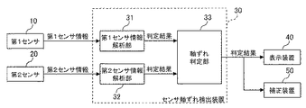
図1は、本発明の実施の形態1におけるセンサ軸ずれ検出装置30の構成を示すブロック図である。また、この図1におけるセンサ軸ずれ検出装置30には、第1センサ10と、第2センサ20と、表示装置40と、補正装置50とが接続されている。
Embodiment 1 FIG.
FIG. 1 is a block diagram showing a configuration of a sensor axis
なお、本実施の形態1においては、座標軸の基準となる第1センサ10と、軸ずれ検出の対象となる第2センサ20との2つのセンサ間の軸ずれを検出するように、センサ軸ずれ検出装置30を構成する場合を例示する。また、以降では、センサ軸ずれ検出装置30を、検出装置30と省略する。
In the first embodiment, the sensor axis deviation is detected so as to detect the axis deviation between the two sensors, the
第1センサ10は、自身の検出可能である領域(以降では、第1検出領域11と称す)に存在する物体を検出し、検出した物体に関する情報を第1センサ情報として検出し、検出装置30に出力する。同様に、第2センサ20は、自身の検出可能である領域(以降では、第2検出領域21と称す)に存在する物体を検出し、検出した物体に関する情報を第2センサ情報として検出し、検出装置30に出力する。また、第1センサ10および第2センサ20のそれぞれは、同一の物体を検出対象60とし、このような検出処理を独立に行う。
The
ここで、第1センサ情報および第2センサ情報には、例えば、検出された物体までの距離、センサの視線方向(検出方向)からみた物体の角度および物体の相対速度が含まれる。また、第2センサ20においては、例えば、センサの視線方向が固定されており、ある特定の方角に存在する物体のみを検出するとともに、検出された物体の角度を計測しない代わりに、物体の距離を計測できるようにして構成してもよい。
Here, the first sensor information and the second sensor information include, for example, the distance to the detected object, the angle of the object viewed from the sight line direction (detection direction) of the sensor, and the relative velocity of the object. Further, in the
また、第1センサ10および第2センサ20のそれぞれの検出特性(検出領域)は、用いるセンサの種類によってあらかじめ決まっている既知のものである。検出装置30には、第1センサ10と第2センサ20との間で軸ずれが発生していないと仮定した時のこれらの検出特性があらかじめ設定(記憶)されている。なお、以降では、第1センサ10と第2センサ20との間で軸ずれが発生していないと仮定した時の、第1センサ10の第1検出領域11を第1設定覆域12と称し、第2センサ20の第2検出領域21を第2設定覆域22と称す。
The detection characteristics (detection regions) of the
検出装置30は、第1センサ情報解析部31、第2センサ情報解析部32および軸ずれ判定部33を有する。
The
第1センサ情報解析部31は、第1解析処理として、第1センサ10が出力する第1センサ情報を取得し、取得した第1センサ情報に基づいて、検出対象60が第1検出領域11に存在するか否かを判定する。また、第1センサ情報解析部31は、さらに第1解析処理として、取得した第1センサ情報に基づいて、検出対象60が第2設定覆域22に存在するか否かを判定する。
The 1st sensor
第2センサ情報解析部32は、第2解析処理として、第2センサ20が出力する第2センサ情報を取得し、取得した第2センサ情報に基づいて、検出対象60が第2検出領域21に存在するか否かを判定する。また、第1センサ情報解析部31および第2センサ情報解析部32は、このような判定結果(解析結果)を軸ずれ判定部33に出力する。
The second sensor
軸ずれ判定部33は、第1センサ情報解析部31および第2センサ情報解析部32が出力した判定結果を取得し、取得した判定結果に基づいて、第1センサ10と第2センサ20との間で軸ずれが発生しているか否かを判定する。また、軸ずれ判定部33は、このような判定結果を軸ずれ情報として外部に出力する。
The axis
ここで、例えば、図1で例示したように、軸ずれ判定部33が外部の表示装置40に軸ずれ情報を出力するように構成した場合、表示装置40は、この軸ずれ情報を表示する。これにより、第1センサ10と第2センサ20との間で軸ずれが発生しているか否かを知ることができる。
Here, for example, as illustrated in FIG. 1, when the axis
また、図1で例示したように、軸ずれ判定部33が外部の補正装置50に軸ずれ情報を出力するように構成した場合、補正装置50は、第1センサ10と第2センサ20との間で軸ずれが有りと判定されていれば、公知の技術を用いて、この軸ずれを補正する。
Further, as illustrated in FIG. 1, when the axis
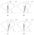
次に、本実施の形態1における検出装置30の動作について、図2を参照しながら説明する。図2は、本発明の実施の形態1において、第1センサ10の第1検出領域11および第1設定覆域12と、第2センサ20の第2検出領域21および第2設定覆域22と、検出対象60との位置関係の一例を示す説明図である。なお、検出装置30においては、第1センサ10の第1検出領域11および第1設定覆域12が一致していることを前提として、第1センサ10と第2センサ20との間で軸ずれが発生しているか否かを判定するように構成されている。
Next, the operation of the
図2(a)は、検出対象60が第1センサ10の第1検出領域11と、第2センサ20の第2検出領域21および第2設定覆域22とに存在する状況の一例を示している。また、図2(a)の状況では、第2センサ20の実際の覆域に相当する第2検出領域21と、第2設定覆域22とが一致している(同じである)。
FIG. 2A shows an example of a situation in which the
このような状況の場合、検出装置30は、第1センサ10と第2センサ20との間で軸ずれが発生していないと判定する。
In such a situation, the
図2(b)は、検出対象60が第1検出領域11および第2設定覆域22に存在し、かつ第2検出領域21に存在しない状況の一例を示している。すなわち、図2(b)の状況では、第2検出領域21と第2設定覆域22とが一致しておらず、本来、軸ずれが発生していなければ第2センサ20が検出できるはずの検出対象60が実際には検出できていない状況である。
FIG. 2B shows an example of a situation in which the
このような状況の場合、検出装置30は、第1センサ10と第2センサ20との間で軸ずれが発生していると判定する。
In such a situation, the
図2(c)は、検出対象60が第1検出領域11および第2検出領域21に存在し、かつ第2設定覆域22に存在しない状況の一例を示している。すなわち、図2(c)の状況では、第2検出領域21と第2設定覆域22とが一致しておらず、本来、軸ずれが発生していなければ第2センサ20が検出できないはずの検出対象60が実際には検出できている状況である。
FIG. 2C shows an example of a situation in which the
このような状況の場合、図2(b)の状況と同様に、検出装置30は、第1センサ10と第2センサ20との間で軸ずれが発生していると判定する。
In such a situation, as in the situation of FIG. 2B, the
図2(d)は、検出対象60が第1検出領域11に存在し、かつ第2検出領域21および第2設定覆域22に存在しない状況の一例を示している。また、図2(d)の状況では、第2検出領域21と第2設定覆域22とが一致している。
FIG. 2D shows an example of a situation in which the
このような状況の場合、図2(a)の状況と同様に、第1センサ10と第2センサ20との間で軸ずれが発生していないと判定する。
In the case of such a situation, it is determined that no axial deviation has occurred between the
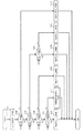
次に、本実施の形態1における検出装置30の動作(軸ずれ判定処理)について、図3のフローチャートを参照しながら説明する。図3は、本発明の実施の形態1におけるセンサ軸ずれ検出装置30の一連の動作を示すフローチャートである。なお、図3のフローチャートは、例えば、あらかじめ設定されたタイミングで実行されるように構成される。
Next, the operation (axial deviation determination process) of the
ステップS101(「センサ検出データ取得」ステップ)において、第1センサ情報解析部31は、第1センサ10から第1センサ情報を取得し、第2センサ情報解析部32は、第2センサ20から第2センサ情報を取得し、ステップS102へと進む。
In step S101 ("sensor detection data acquisition" step), the first sensor
ステップS102(「第1センサ検出?」ステップ)において、第1センサ情報解析部31は、取得した第1センサ情報に基づいて、検出対象60が第1検出領域11に存在するか否かを判定する。
In step S102 ("first sensor detection?" Step), the first sensor
そして、第1センサ情報解析部31は、検出対象60が第1検出領域11に存在する(すなわち、Yes)と判定した場合には、ステップS103へと進む。一方、第1センサ情報解析部31は、検出対象60が第1検出領域11に存在しない(すなわち、No)と判定した場合には、ステップS110へと進む。この場合、ステップS110において、軸ずれ判定部33は、「軸ずれ不明」と判定し、一連の処理を終了する。
If the first sensor
ステップS103(「第2センサ覆域内?」ステップ)において、第1センサ情報解析部31は、取得した第1センサ情報と、あらかじめ設定された第2センサ20の設定覆域22とに基づいて、第1検出領域11に存在する検出対象60が第2設定覆域22に存在するか否かを判定する。
In step S103 ("inside second sensor coverage?" Step), the first sensor
そして、第1センサ情報解析部31は、検出対象60が第2設定覆域22に存在する(すなわち、Yes)と判定した場合には、ステップS104へと進む。一方、第1センサ情報解析部31は、検出対象60が第2設定覆域22に存在しない(すなわち、No)と判定した場合には、ステップS107へと進む。
If the first sensor
ステップS104(「第2センサ検出?」ステップ)において、第2センサ情報解析部32は、取得した第2センサ情報に基づいて、第2設定覆域22に存在する検出対象60が第2検出領域21に存在するか否かを判定する。
In step S104 (“second sensor detection?” Step), the second sensor
そして、第2センサ情報解析部32は、検出対象60が第2検出領域21に存在する(すなわち、Yes)と判定した場合には、ステップS105へと進む。この場合、ステップS105において、軸ずれ判定部33は、「軸ずれなし」と判定し、一連の処理を終了する。一方、第2センサ情報解析部32は、検出対象60が第2検出領域21に存在しない(すなわち、No)と判定した場合には、ステップS106へと進む。この場合、ステップS106において、軸ずれ判定部33は、「軸ずれあり」と判定し、一連の処理を終了する。
If the second sensor
ステップS107(「第2センサ検出?」ステップ)において、第2センサ情報解析部32は、取得した第2センサ情報に基づいて、第2設定覆域22に存在しない検出対象60が第2検出領域21に存在するか否かを判定する。
In step S107 (“second sensor detection?” Step), the second sensor
そして、第2センサ情報解析部32は、検出対象60が第2検出領域21に存在する(すなわち、Yes)と判定した場合には、ステップS108へと進む。この場合、ステップS108において、軸ずれ判定部33は、「軸ずれあり」と判定し、一連の処理を終了する。一方、第2センサ情報解析部32は、検出対象60が第2検出領域21に存在しない(すなわち、No)と判定した場合には、ステップS109へと進む。この場合、ステップS109において、軸ずれ判定部33は、「軸ずれなし」と判定し、一連の処理を終了する。
If the second sensor
なお、先の図2(a)〜(d)のそれぞれの状況において、図3のフローチャートは以下のように実行される。 In each of the situations shown in FIGS. 2A to 2D, the flowchart of FIG. 3 is executed as follows.
すなわち、図2(a)の状況では、ステップS101→S102→S103→S104→S105の順に実行され、軸ずれ判定部33は、「軸ずれなし」と判定することとなる。また、図2(b)の状況では、ステップS101→S102→S103→S104→S106の順に実行され、軸ずれ判定部33は、「軸ずれあり」と判定することとなる。
That is, in the situation of FIG. 2A, the steps are executed in the order of steps S101 → S102 → S103 → S104 → S105, and the shaft
図2(c)の状況では、ステップS101→S102→S103→S107→S108の順に実行され、軸ずれ判定部33は、「軸ずれあり」と判定することとなる。また、図2(d)の状況では、ステップS101→S102→S103→S107→S109の順に実行され、軸ずれ判定部33は、「軸ずれなし」と判定することとなる。
In the situation of FIG. 2C, the process is executed in the order of steps S101 → S102 → S103 → S107 → S108, and the axis
以上、本実施の形態1によれば、第1センサおよび第2センサは、同一の物体を検出対象とし、第1センサの第1検出領域に存在する検出対象が、あらかじめ設定されている第2センサの設定覆域に存在し、かつ第2検出領域に存在しない場合、第1センサと第2センサとの間で軸ずれが発生している(「軸ずれあり」)と判定するように構成する。 As described above, according to the first embodiment, the first sensor and the second sensor have the same object as a detection target, and the detection target existing in the first detection region of the first sensor is set in advance. It is configured to determine that an axis deviation has occurred between the first sensor and the second sensor (“with axis deviation”) when the sensor exists in the set coverage area of the sensor and does not exist in the second detection area. To do.
また、第1センサの第1検出領域に存在する検出対象が、あらかじめ設定されている第2センサの設定覆域に存在せず、かつ第2検出領域に存在する場合、第1センサと第2センサとの間で軸ずれが発生している(「軸ずれあり」)と判定するように構成する。 Further, when the detection target existing in the first detection area of the first sensor does not exist in the preset coverage area of the second sensor and exists in the second detection area, the first sensor and the second sensor It is configured to determine that an axis deviation has occurred with the sensor (“axial deviation”).
これにより、簡単な構成で、すべてのセンサで同一物体を検出している(すべてのセンサの検出領域に同一物体が存在する)とは限らない状況であっても、複数のセンサ間の軸ずれを検出することができる。 As a result, even with a simple configuration, the same object is detected by all the sensors (the same object exists in the detection area of all the sensors), but the axis misalignment between multiple sensors Can be detected.
なお、本実施の形態1では、第1センサ10と第2センサ20との2つのセンサ間の軸ずれを検出する場合を例示して説明したが、センサの数は2つに限定されるものではなく、3つ以上のセンサに対しても本願発明を適用することができ、同様に軸ずれを検出することができる。
In the first embodiment, the case of detecting the axial deviation between the two sensors of the
実施の形態2.
本発明の実施の形態2では、先の実施の形態1と異なり、副覆域の存在を考慮する場合について説明する。なお、本実施の形態2における検出装置30としては、先の実施の形態1における検出装置30と比べて、構成は同様であるが、動作が異なる。したがって、ここでは、先の実施の形態1における検出装置30とは異なる動作を中心に説明する。
Embodiment 2. FIG.
In the second embodiment of the present invention, unlike the first embodiment, the case where the existence of the sub-covered area is considered will be described. The
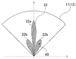
図4は、本発明の実施の形態2において、第1センサ10の第1検出領域11および第1設定覆域12と、第2センサ20の第2設定覆域22に相当する設定主覆域22aおよび設定副覆域22bと、検出対象60との位置関係の一例を示す説明図である。なお、図4では、第2センサ20の第2検出領域21と第2設定覆域22とが一致している状況を示しているので、第2検出領域21の図示を省略している。
FIG. 4 is a set main coverage corresponding to the
ここで、先の実施の形態1と異なり、第2センサ20で一部に限定した検出処理を行う範囲(主覆域)以外に、検出が期待されていない領域(副覆域)が存在する状況を想定する。例えば、第2センサ20がミリ波レーダ等である場合、主覆域としてメインローブを、副覆域としてサイドローブをそれぞれ設定することができる。このように、副覆域の存在を考慮する場合、従来においては、第2センサ20によって検出された検出対象60が第2検出領域21のうちの主覆域内と副覆域内とのどちらに存在するのかを区別することができない。
Here, unlike the first embodiment, there is an area (sub-covered area) where detection is not expected other than a range (main covered area) where detection processing limited to a part is performed by the
しかしながら、本実施の形態2における検出装置30は、先の実施の形態1と同様の動作をするとともに、さらに、第2センサ20によって検出された検出対象60が主覆域内と副覆域内とのどちらに存在するのかを区別することができる。
However, the
具体的には、本実施の形態2では、第1センサ情報解析部31には、第2設定覆域22として設定主覆域22aおよび設定副覆域22bに分けてあらかじめ設定されるように構成する。すなわち、第1センサ情報解析部31には、既知である第2センサ20の主覆域および副覆域のそれぞれの検出特性(検出領域)が設定主覆域22aおよび設定副覆域22bとしてあらかじめ設定される。
Specifically, in the second embodiment, the first sensor
次に、本実施の形態2における検出装置30の動作について、図5のフローチャートを参照しながら説明する。図5は、本発明の実施の形態2におけるセンサ軸ずれ検出装置30の一連の動作を示すフローチャートである。なお、図5のフローチャートは、例えば、あらかじめ設定されたタイミングで実行されるように構成される。また、図5のフローチャートは、先の図3のフローチャートと比べて、新しいステップとしてステップS111、S112が追加されている。したがって、これらの追加されたステップを中心に説明し、先の図3のフローチャートと同様のステップについては説明を省略する。
Next, the operation of the
ステップS104において、第2センサ情報解析部32は、取得した第2センサ情報に基づいて、第2設定覆域22に存在する検出対象60が第2検出領域21に存在する(すなわち、Yes)と判定した場合、ステップS111へと進む。
In step S104, the second sensor
ステップS111(「第2センサ主覆域内?」ステップ)において、第1センサ情報解析部31は、第1センサ情報とあらかじめ設定された設定主覆域22aとに基づいて、第1検出領域11、第2設定覆域22および第2検出領域21に存在する検出対象60が設定主覆域22aに存在するか否かを判定する。
In step S111 ("second sensor main coverage area?" Step), the first sensor
そして、第1センサ情報解析部31は、検出対象60が設定主覆域22aに存在する(すなわち、Yes)と判定した場合には、ステップS105へと進む。この場合、ステップS105において、先の実施の形態1と同様に、軸ずれ判定部33は、「軸ずれなし」と判定し、一連の処理を終了する。一方、第1センサ情報解析部31は、検出対象60が設定主覆域22aに存在しない(すなわち、No)と判定した場合には、ステップS112へと進む。この場合、ステップS112において、軸ずれ判定部33は、第2センサ20の副覆域で、検出対象60を検出したと判定する。
If the first sensor
このように、図5のフローチャートにおいてステップS111、S112を新たに追加することで、第2センサ20によって検出された検出対象60が主覆域内と副覆域内とのどちらに存在するのかを区別することができる。すなわち、第1センサ10と第2センサ20との間で軸ずれが発生しているか否かを、第2センサ20の副覆域内での検出可能性を含めて判定することができる。
In this manner, by newly adding steps S111 and S112 in the flowchart of FIG. 5, it is distinguished whether the
なお、先の図4の状況において、図5のフローチャートは以下のように実行される。すなわち、図4の状況では、ステップS101→S102→S103→S104→S111→S112の順に実行され、軸ずれ判定部33は、第2センサ20の副覆域で、検出対象60を検出したと判定することとなる。
In the above situation of FIG. 4, the flowchart of FIG. 5 is executed as follows. That is, in the situation of FIG. 4, steps S101 → S102 → S103 → S104 → S111 → S112 are executed in this order, and the axis
以上、本実施の形態2によれば、第2センサの設定覆域として設定主覆域および設定副覆域に分けられてあらかじめ設定され、第1センサの第1検出領域に存在する検出対象が、第2センサの設定覆域および第2検出領域に存在し、かつ第2センサの設定主覆域に存在しない場合、第2センサの副覆域で、検出対象を検出したと判定するように構成する。 As described above, according to the second embodiment, the detection target existing in the first detection area of the first sensor is divided into the setting main coverage area and the setting sub-coverage area as the setting coverage area of the second sensor. When it is present in the set coverage area and the second detection area of the second sensor and does not exist in the set main coverage area of the second sensor, it is determined that the detection target is detected in the secondary coverage area of the second sensor. Configure.
これにより、先の実施の形態1と同様の効果が得られるとともに、簡単な構成で、第2センサの検出が主覆域内と副覆域内のどちらであるかを区別することができる。 As a result, the same effects as those of the first embodiment can be obtained, and whether the detection of the second sensor is in the main coverage area or the sub coverage area can be distinguished with a simple configuration.
また、従来技術においては、例えば、ミリ波レーダにおけるサイドローブなど、検出が期待されていない信号は存在しないことを前提とするので、もしそのような信号が存在した場合、誤って軸ずれが検出されてしまう可能性がある。これに対して、本実施の形態2におけるセンサ軸ずれ検出装置では、副覆域の存在を考慮して構成されているので、誤って軸ずれを検出することがない。 In addition, in the prior art, for example, it is assumed that there is no signal that is not expected to be detected, such as a side lobe in a millimeter wave radar, so if such a signal exists, an axis misalignment is detected by mistake. There is a possibility of being. On the other hand, since the sensor axis deviation detection device according to the second embodiment is configured in consideration of the existence of the sub-covered area, the axis deviation is not erroneously detected.
実施の形態3.
本発明の実施の形態3では、先の実施の形態2と異なり、第2センサ20の設定副覆域22bの一部が第1センサ10の検出領域11の外側にあることを考慮する場合について説明する。なお、本実施の形態3における検出装置30としては、先の実施の形態1、2における検出装置30と比べて、構成は同様であるが、動作が異なる。したがって、ここでは、先の実施の形態1、2における検出装置30とは異なる動作を中心に説明する。
In the third embodiment of the present invention, unlike the second embodiment, a case where a part of the setting
図6は、本発明の実施の形態3において、第1センサ10の第1検出領域11および第1設定覆域12と、第2センサ20の第2設定覆域22に相当する設定主覆域22aおよび設定副覆域22bと、検出対象60との位置関係の一例を示す説明図である。なお、図6では、先の図4と同様に、第2センサ20の第2検出領域21と第2設定覆域22とが一致している状況を示しているので、第2検出領域21の図示を省略している。
FIG. 6 shows a main setting area corresponding to the
ここで、先の実施の形態2と異なり、図6に例示するように、第1センサ10の第1検出領域11と、第2センサ20の設定副覆域22bとが重複しない領域が存在する状況を想定する。
Here, unlike the second embodiment, as illustrated in FIG. 6, there is a region where the
このような状況をより一般的に示したものが図7に相当する。図7は、本発明の実施の形態3において、第1センサ10の第1検出領域11と第2センサ20の設定主覆域22aおよび設定副覆域22bとによって分類される領域を示す概念図である。なお、第2センサ20の設定主覆域22aおよび設定副覆域22bのそれぞれは、図6に示すように互いに重複しないことを前提としている。
A more general illustration of such a situation corresponds to FIG. FIG. 7 is a conceptual diagram showing areas classified by the
図7において、領域(1)は、検出対象60が第1センサ10の第1検出領域11に存在し、かつ第2センサ20の設定主覆域22aおよび設定副覆域22bに存在しない状況に相当する。また、領域(2)は、検出対象60が設定主覆域22aに存在し、かつ第1検出領域11および設定副覆域22bに存在しない状況に相当する。さらに、領域(3)は、検出対象60が第1検出領域11および設定主覆域22aに存在し、かつ設定副覆域22bに存在しない状況に相当する。
In FIG. 7, the region (1) is in a situation where the
領域(4)は、検出対象60が第1検出領域11および設定副覆域22bに存在し、かつ設定主覆域22aに存在しない状況に相当する。また、領域(5)は、検出対象60が設定副覆域22bに存在し、かつ第1検出領域11および設定主覆域22aに存在しない状況に相当する。さらに、領域(6)は、検出対象60が第1検出領域11、設定主覆域22aおよび設定副覆域22bに存在しない状況に相当する。
The area (4) corresponds to a situation in which the
次に、本実施の形態3における検出装置30の動作について、図8のフローチャートを参照しながら説明する。図8は、本発明の実施の形態3におけるセンサ軸ずれ検出装置30の一連の動作を示すフローチャートである。なお、図8のフローチャートは、例えば、あらかじめ設定されたタイミングで実行されるように構成される。また、図8のフローチャートは、先の図5のフローチャートと比べて、新しいステップとしてステップS113、S114が追加されている。したがって、これらの新しいステップを中心に説明し、先の図3、図5のフローチャートと同様のステップについては説明を省略する。
Next, the operation of the
ステップS102において、第1センサ情報解析部31は、取得した第1センサ情報に基づいて、検出対象60が第1検出領域11に存在しない(すなわち、No)と判定した場合には、ステップS113へと進む。
In step S102, if the first sensor
ステップS113(「第2センサ検出?」ステップ)において、第2センサ情報解析部32は、取得した第2センサ情報に基づいて、第1検出領域11に存在しない検出対象60が第2検出領域21に存在するか否かを判定する。
In step S113 (“second sensor detection?” Step), the second sensor
そして、ステップS113において、第2センサ情報解析部32は、検出対象60が第2検出領域21に存在しない(すなわち、No)と判定した場合には、ステップS110へと進む。この場合、ステップS110において、先の実施の形態1、2と同様に、軸ずれ判定部33は、「軸ずれ不明」と判定し、一連の処理を終了する。
If the second sensor
一方、ステップS113において、第2センサ情報解析部32は、検出対象60が第2検出領域21に存在する(すなわち、Yes)と判定した場合には、ステップS114へと進む。この場合、ステップS114において、軸ずれ判定部33は、軸ずれの有無を判定することなく、第2センサ20のみで検出対象60を検出したと判定し、一連の処理を終了する。
On the other hand, when the second sensor
このように、図8のフローチャートにおいてステップS113、S114を新たに追加することで、第2センサ20によって検出された検出対象60が第2センサ20のみで検出されたかを判定することができる。すなわち、第1センサ10と第2センサ20との間で軸ずれが発生しているか否かを、第2センサ20の副覆域内での検出可能性、および第1センサの覆域外での検出可能性を含めて判定することができる。
As described above, by newly adding steps S113 and S114 in the flowchart of FIG. 8, it is possible to determine whether the
次に、本実施の形態3における検出装置30の動作について、先の図7、図8を参照しながらさらに説明する。
Next, the operation of the
第1センサ10で検出対象60を検出するともに検出対象60が第2センサ20の第2設定覆域22に存在し、かつ第2センサ20で検出対象60を検出するとともに検出対象60が第2センサ20の設定主覆域22aに存在する場合、検出対象60は、領域(3)に存在する。この場合、ステップS105において、軸ずれ判定部33は、「軸ずれなし」と判定することとなる。
The
第1センサ10で検出対象60を検出するともに検出対象60が第2センサ20の第2設定覆域22に存在し、かつ第2センサ20で検出対象60を検出するとともに検出対象60が第2センサ20の設定主覆域22aに存在しない場合、検出対象60は、領域(4)に存在する。この場合、ステップS112において、軸ずれ判定部33は、第2センサ20の副覆域で、検出対象60を検出したと判定する。
The
第1センサ10で検出対象60を検出するともに検出対象60が第2センサ20の第2設定覆域22に存在し、かつ第2センサ20で検出対象60を検出していない場合、検出対象60は、領域(1)〜(6)のいずれの領域にも存在しない。この場合、ステップS106において、軸ずれ判定部33は、「軸ずれあり」と判定することとなる。
When the
第1センサ10で検出対象60を検出するとともに検出対象60が第2センサ20の第2設定覆域22に存在せず、かつ第2センサ20で検出対象60を検出している場合、検出対象60は、領域(1)〜(6)のいずれの領域にも存在しない。この場合、ステップS108において、軸ずれ判定部33は、「軸ずれあり」と判定することとなる。
When the
第1センサ10で検出対象60を検出するとともに検出対象60が第2センサ20の第2設定覆域22に存在せず、かつ第2センサ20で検出対象60を検出していない場合、検出対象60は、領域(1)に存在する。この場合、ステップS109において、軸ずれ判定部33は、「軸ずれなし」と判定することとなる。
When the
第1センサ10で検出対象60を検出せず、かつ第2センサ20で検出対象60を検出している場合、検出対象60は、領域(2)および領域(5)のいずれかに存在する。この場合、ステップS114において、軸ずれ判定部33は、第2センサ20のみで検出対象60を検出したと判定することとなる。
When the
第1センサ10で検出対象60を検出せず、かつ第2センサ20で検出対象60を検出していない場合、検出対象60は、領域(6)に存在する。この場合、ステップS110において、軸ずれ判定部33は、「軸ずれ不明」と判定することとなる。
When the
以上、本実施の形態3によれば、第1検出領域に存在しない検出対象が第2センサの第2検出領域に存在する場合、第2センサのみで検出対象を検出したと判定するように構成する。 As described above, according to the third embodiment, when a detection target that does not exist in the first detection region exists in the second detection region of the second sensor, it is determined that the detection target is detected only by the second sensor. To do.
これにより、先の実施の形態1、2と同様の効果が得られるとともに、簡単な構成で、2センサによって検出された検出対象が第2センサのみで検出されたかを判定することができる。 As a result, the same effects as those of the first and second embodiments can be obtained, and it can be determined whether the detection target detected by the two sensors is detected only by the second sensor with a simple configuration.
なお、本実施の形態3では、第1センサ10で検出対象60を検出しておらず、かつ第2センサ20で検出対象60を検出していれば、第2センサ20のみで検出対象60を検出したと判定するように構成したがこれに限定されない。すなわち、第1センサ10の検出領域11内に設定主覆域22aが含まれていることを前提とする場合においては、第1センサ10で検出対象60を検出しておらず、かつ第2センサ20で検出対象60を検出していれば、検出対象60が第2センサ20の副覆域で検出されたと判定するように構成してもよい。
In the third embodiment, if the
10 第1センサ、11 第1検出領域、12 第1設定覆域、20 第2センサ、21 第2検出領域、22 第2設定覆域、22a 設定主覆域、22b 設定副覆域、30 軸ずれ検出装置、31 第1センサ情報解析部、32 第2センサ情報解析部、33 軸ずれ判定部、40 表示装置、50 補正装置、60 検出対象。
DESCRIPTION OF
Claims (3)
前記第1センサおよび前記第2センサは、同一の物体を検出対象とし、
前記第1センサの座標軸と第2センサの座標軸とが一致しないときの、前記第1センサの座標軸に対する前記第2センサの座標軸のずれを前記軸ずれとして検出し、
前記第1センサから取得した前記第1センサ情報に基づいて、前記検出対象が前記第1検出領域に存在するか否かを判定するとともに、前記第1センサと前記第2センサとの間で前記軸ずれが発生していないと仮定した時の前記第2検出領域に対応する領域であり、あらかじめ設定されている前記第2センサの設定覆域に前記検出対象が存在するか否かを判定する第1センサ情報解析部と、
前記第2センサから取得した前記第2センサ情報に基づいて、前記検出対象が前記第2検出領域に存在するか否かを判定する第2センサ情報解析部と、
前記第1センサ情報解析部による判定結果および前記第2センサ情報解析部による判定結果にしたがって、前記第1センサと前記第2センサとの間での軸ずれの有無を判定する軸ずれ判定部と、
を備え、
前記軸ずれ判定部は、
前記第1センサ情報解析部により前記検出対象が前記第1検出領域に存在すると判定された場合において、前記第1センサ情報解析部により前記第2センサの設定覆域に前記検出対象が存在すると判定され、かつ、前記第2センサ情報解析部により前記検出対象が前記第2検出領域に存在しないと判定された場合、
または
前記第1センサ情報解析部により前記検出対象が前記第1検出領域に存在すると判定された場合において、前記第1センサ情報解析部により前記第2センサの設定覆域に前記検出対象が存在しないと判定され、かつ、前記第2センサ情報解析部により前記検出対象が前記第2検出領域に存在すると判定された場合、
前記軸ずれが有りと判定し、
前記第1センサ情報解析部には、前記第2センサの設定覆域として前記第2センサのメインローブに当たる設定主覆域および前記第2センサのサイドローブに当たる設定副覆域に分けられてあらかじめ設定され、
前記第1センサ情報解析部は、
前記第1センサから取得した前記第1センサ情報に基づいて、あらかじめ設定されている前記第2センサの前記設定主覆域に前記検出対象が存在するか否かをさらに判定し、
前記軸ずれ判定部は、
前記第1センサ情報解析部により前記検出対象が前記第1検出領域に存在すると判定された場合において、
前記第1センサ情報解析部により前記第2センサの設定覆域に前記検出対象が存在すると判定され、前記第2センサ情報解析部により前記検出対象が前記第2検出領域に存在すると判定され、かつ、前記第1センサ情報解析部により前記第2センサの前記設定主覆域に前記検出対象が存在しないと判定された場合、
前記第2センサの前記設定副覆域で、前記検出対象を検出したと判定し、
前記第2センサの前記設定覆域の少なくとも一部は、前記第1検出領域に包含され、
前記第2センサの前記設定主覆域の少なくとも一部は、前記第1検出領域に包含される センサ軸ずれ検出装置。 A first sensor that detects, as first sensor information, information about the position of an object that exists in the first detection area, and a second sensor that detects information about the position of an object that exists in the second detection area as second sensor information. A sensor shaft misalignment detecting device for detecting a shaft misalignment between
The first sensor and the second sensor target the same object,
A deviation of the coordinate axis of the second sensor with respect to the coordinate axis of the first sensor when the coordinate axis of the first sensor and the coordinate axis of the second sensor do not coincide with each other is detected as the axis deviation;
Based on the first sensor information acquired from the first sensor, it is determined whether or not the detection target is present in the first detection region, and between the first sensor and the second sensor, It is an area corresponding to the second detection area when it is assumed that no axis deviation has occurred, and it is determined whether or not the detection target exists in a preset coverage area of the second sensor. A first sensor information analysis unit;
Based on the second sensor information acquired from the second sensor, a second sensor information analysis unit that determines whether the detection target exists in the second detection region;
An axis misalignment determining unit that determines whether or not there is an axis misalignment between the first sensor and the second sensor according to the determination result by the first sensor information analyzing unit and the determination result by the second sensor information analyzing unit; ,
With
The axis deviation determination unit
When the first sensor information analysis unit determines that the detection target exists in the first detection region, the first sensor information analysis unit determines that the detection target exists in the set coverage area of the second sensor. And when the second sensor information analysis unit determines that the detection target does not exist in the second detection region,
Alternatively, when the first sensor information analysis unit determines that the detection target exists in the first detection region, the first sensor information analysis unit does not have the detection target in the set coverage area of the second sensor. And the second sensor information analysis unit determines that the detection target exists in the second detection area,
It is determined that there is an axis deviation ,
In the first sensor information analysis unit, the setting range of the second sensor is divided into a setting main coverage area corresponding to the main lobe of the second sensor and a setting sub-coverage area corresponding to the side lobe of the second sensor. And
The first sensor information analysis unit includes:
Based on the first sensor information acquired from the first sensor, further determine whether or not the detection target exists in the set main coverage area of the second sensor that is set in advance,
The axis deviation determination unit
In the case where the first sensor information analysis unit determines that the detection target exists in the first detection region,
The first sensor information analysis unit determines that the detection target exists in the set coverage of the second sensor, the second sensor information analysis unit determines that the detection target exists in the second detection region; and When the first sensor information analysis unit determines that the detection target does not exist in the set main coverage area of the second sensor,
It is determined that the detection target is detected in the setting sub-coverage area of the second sensor,
At least a part of the set coverage area of the second sensor is included in the first detection area,
At least a part of the set main coverage area of the second sensor is a sensor axis deviation detection device included in the first detection area .
前記軸ずれ判定部は、
前記第1センサ情報解析部により前記検出対象が前記第1検出領域に存在しないと判定され、かつ、前記第2センサ情報解析部により前記検出対象が前記第2検出領域に存在すると判定された場合、
前記第2センサのみで前記検出対象を検出したと判定する
センサ軸ずれ検出装置。 In the sensor axis deviation detecting device according to claim 1 ,
The axis deviation determination unit
When the first sensor information analysis unit determines that the detection target does not exist in the first detection region, and the second sensor information analysis unit determines that the detection target exists in the second detection region ,
A sensor axis deviation detection device that determines that the detection target is detected only by the second sensor.
前記第1センサの座標軸と第2センサの座標軸とが一致しないときの、前記第1センサの座標軸に対する前記第2センサの座標軸のずれを前記軸ずれとして検出し、
前記第1センサおよび前記第2センサは、同一の物体を検出対象とし、
前記第1センサから取得した前記第1センサ情報に基づいて、前記検出対象が前記第1検出領域に存在するか否かを判定するとともに、前記第1センサと前記第2センサとの間で前記軸ずれが発生していないと仮定した時の前記第2検出領域に対応する領域であり、あらかじめ設定されている前記第2センサの設定覆域に前記検出対象が存在するか否かを判定する第1センサ情報解析ステップと、
前記第2センサから取得した前記第2センサ情報に基づいて、前記検出対象が前記第2検出領域に存在するか否かを判定する第2センサ情報解析ステップと、
前記第1センサ情報解析ステップでの判定結果および前記第2センサ情報解析ステップでの判定結果にしたがって、前記第1センサと前記第2センサとの間での軸ずれの有無を判定する軸ずれ判定ステップと、
を備え、
前記軸ずれ判定ステップで、
前記第1センサ情報解析ステップで前記検出対象が前記第1検出領域に存在すると判定された場合において、前記第1センサ情報解析ステップで前記第2センサの設定覆域に前記検出対象が存在すると判定され、かつ、前記第2センサ情報解析ステップで前記検出対象が前記第2検出領域に存在しないと判定された場合、
または
前記第1センサ情報解析ステップで前記検出対象が前記第1検出領域に存在すると判定された場合において、前記第1センサ情報解析ステップで、前記第2センサの設定覆域に前記検出対象が存在しないと判定され、かつ、前記第2センサ情報解析ステップで、前記検出対象が前記第2検出領域に存在すると判定された場合、
前記軸ずれが有りと判定し、
前記第1センサ情報解析ステップでは、前記第2センサの設定覆域として前記第2センサのメインローブに当たる設定主覆域および前記第2センサのサイドローブに当たる設定副覆域に分けられてあらかじめ設定され、
前記第1センサ情報解析ステップでは、
前記第1センサから取得した前記第1センサ情報に基づいて、あらかじめ設定されている前記第2センサの前記設定主覆域に前記検出対象が存在するか否かをさらに判定し、
前記軸ずれ判定ステップでは、
前記第1センサ情報解析ステップにおいて前記検出対象が前記第1検出領域に存在すると判定された場合において、
前記第1センサ情報解析ステップにおいて前記第2センサの設定覆域に前記検出対象が存在すると判定され、前記第2センサ情報解析ステップにおいて前記検出対象が前記第2検出領域に存在すると判定され、かつ、前記第1センサ情報解析ステップにおいて前記第2センサの前記設定主覆域に前記検出対象が存在しないと判定された場合、
前記第2センサの前記設定副覆域で、前記検出対象を検出したと判定し、
前記第2センサの前記設定覆域の少なくとも一部は、前記第1検出領域に包含され、
前記第2センサの前記設定主覆域の少なくとも一部は、前記第1検出領域に包含される センサ軸ずれ検出方法。 A first sensor that detects, as first sensor information, information about the position of an object that exists in the first detection area, and a second sensor that detects information about the position of an object that exists in the second detection area as second sensor information. A sensor axis deviation detection method executed by a sensor axis deviation detection device for detecting an axis deviation between
A deviation of the coordinate axis of the second sensor with respect to the coordinate axis of the first sensor when the coordinate axis of the first sensor and the coordinate axis of the second sensor do not coincide with each other is detected as the axis deviation;
The first sensor and the second sensor target the same object,
Based on the first sensor information acquired from the first sensor, it is determined whether or not the detection target is present in the first detection region, and between the first sensor and the second sensor, It is an area corresponding to the second detection area when it is assumed that no axis deviation has occurred, and it is determined whether or not the detection target exists in a preset coverage area of the second sensor. A first sensor information analysis step;
A second sensor information analyzing step for determining whether or not the detection target exists in the second detection region based on the second sensor information acquired from the second sensor;
Axis misalignment determination for determining whether or not there is an axis misalignment between the first sensor and the second sensor according to the determination result in the first sensor information analyzing step and the determination result in the second sensor information analyzing step. Steps,
With
In the axis deviation determination step,
When it is determined in the first sensor information analysis step that the detection target exists in the first detection area, it is determined in the first sensor information analysis step that the detection target exists in the set coverage area of the second sensor. And when it is determined in the second sensor information analysis step that the detection target does not exist in the second detection region,
Alternatively, when it is determined in the first sensor information analysis step that the detection target exists in the first detection area, the detection target exists in the set coverage area of the second sensor in the first sensor information analysis step. And when it is determined in the second sensor information analysis step that the detection target is present in the second detection region,
It is determined that there is an axis deviation ,
In the first sensor information analyzing step, the setting coverage of the second sensor is divided into a setting main coverage corresponding to the main lobe of the second sensor and a setting sub-coverage corresponding to the side lobe of the second sensor. ,
In the first sensor information analysis step,
Based on the first sensor information acquired from the first sensor, further determine whether or not the detection target exists in the set main coverage area of the second sensor that is set in advance,
In the axis deviation determination step,
When it is determined in the first sensor information analysis step that the detection target is present in the first detection region,
In the first sensor information analysis step, it is determined that the detection target exists in the set coverage area of the second sensor, in the second sensor information analysis step, it is determined that the detection target exists in the second detection area, and In the first sensor information analysis step, when it is determined that the detection target does not exist in the set main coverage area of the second sensor,
It is determined that the detection target is detected in the setting sub-coverage area of the second sensor,
At least a part of the set coverage area of the second sensor is included in the first detection area,
A sensor axis deviation detection method in which at least a part of the set main coverage area of the second sensor is included in the first detection area .
Priority Applications (1)
| Application Number | Priority Date | Filing Date | Title |
|---|---|---|---|
| JP2014065484A JP5976027B2 (en) | 2014-03-27 | 2014-03-27 | Sensor axis deviation detection device and sensor axis deviation detection method |
Applications Claiming Priority (1)
| Application Number | Priority Date | Filing Date | Title |
|---|---|---|---|
| JP2014065484A JP5976027B2 (en) | 2014-03-27 | 2014-03-27 | Sensor axis deviation detection device and sensor axis deviation detection method |
Publications (2)
| Publication Number | Publication Date |
|---|---|
| JP2015187589A JP2015187589A (en) | 2015-10-29 |
| JP5976027B2 true JP5976027B2 (en) | 2016-08-23 |
Family
ID=54429888
Family Applications (1)
| Application Number | Title | Priority Date | Filing Date |
|---|---|---|---|
| JP2014065484A Active JP5976027B2 (en) | 2014-03-27 | 2014-03-27 | Sensor axis deviation detection device and sensor axis deviation detection method |
Country Status (1)
| Country | Link |
|---|---|
| JP (1) | JP5976027B2 (en) |
Cited By (1)
| Publication number | Priority date | Publication date | Assignee | Title |
|---|---|---|---|---|
| EP3667359A1 (en) * | 2018-12-11 | 2020-06-17 | Volkswagen AG | Method for determining the misalignment of at least one sensor within a set of sensors |
Families Citing this family (4)
| Publication number | Priority date | Publication date | Assignee | Title |
|---|---|---|---|---|
| JP6514828B2 (en) * | 2016-08-12 | 2019-05-15 | 株式会社小糸製作所 | Lighting system and sensor system |
| JP6848725B2 (en) * | 2017-06-29 | 2021-03-24 | 株式会社デンソー | Horizontal axis deviation determination method in the object detection device for vehicles and the object detection device for vehicles |
| JP6637472B2 (en) * | 2017-07-06 | 2020-01-29 | 本田技研工業株式会社 | Information processing method and information processing apparatus |
| RU2742323C2 (en) | 2018-12-29 | 2021-02-04 | Общество с ограниченной ответственностью "Яндекс Беспилотные Технологии" | Method and computer device for determining angular displacement of radar system |
Family Cites Families (10)
| Publication number | Priority date | Publication date | Assignee | Title |
|---|---|---|---|---|
| JPH09142236A (en) * | 1995-11-17 | 1997-06-03 | Mitsubishi Electric Corp | Periphery monitoring method and device for vehicle, and trouble deciding method and device for periphery monitoring device |
| JP3331882B2 (en) * | 1995-12-27 | 2002-10-07 | 株式会社デンソー | Central axis deflection amount calculating device, central axis deflection amount correcting device, and inter-vehicle control device of vehicle obstacle detection device |
| JPH09218265A (en) * | 1996-02-14 | 1997-08-19 | Nissan Motor Co Ltd | Apparatus for automatically correcting center axis of radar |
| JP2000028715A (en) * | 1998-07-14 | 2000-01-28 | Nippon Signal Co Ltd:The | Composite-type radar sensor |
| DE19962997B4 (en) * | 1999-12-24 | 2010-06-02 | Robert Bosch Gmbh | Method for calibrating a sensor system |
| JP2005114542A (en) * | 2003-10-08 | 2005-04-28 | Hitachi Ltd | Obstruction-detecting device and obstruction-warning device using same |
| JP2006011570A (en) * | 2004-06-23 | 2006-01-12 | Daihatsu Motor Co Ltd | Camera calibration method and camera calibration device |
| JP5146716B2 (en) * | 2007-03-01 | 2013-02-20 | マツダ株式会社 | Obstacle detection device for vehicles |
| JP2010249613A (en) * | 2009-04-14 | 2010-11-04 | Toyota Motor Corp | Obstacle recognition device and vehicle control unit |
| JP2011043387A (en) * | 2009-08-20 | 2011-03-03 | Toyota Motor Corp | On-vehicle radar system |
-
2014
- 2014-03-27 JP JP2014065484A patent/JP5976027B2/en active Active
Cited By (2)
| Publication number | Priority date | Publication date | Assignee | Title |
|---|---|---|---|---|
| EP3667359A1 (en) * | 2018-12-11 | 2020-06-17 | Volkswagen AG | Method for determining the misalignment of at least one sensor within a set of sensors |
| US11604245B2 (en) | 2018-12-11 | 2023-03-14 | Volkswagen Aktiengesellschaft | Method for establishing the presence of a misalignment of at least one sensor within a sensor group |
Also Published As
| Publication number | Publication date |
|---|---|
| JP2015187589A (en) | 2015-10-29 |
Similar Documents
| Publication | Publication Date | Title |
|---|---|---|
| JP5976027B2 (en) | Sensor axis deviation detection device and sensor axis deviation detection method | |
| JP6168784B2 (en) | Perimeter monitoring system and axis deviation detection method for perimeter monitoring system | |
| JP6643166B2 (en) | Object recognition device and object recognition method | |
| US10126410B2 (en) | Determination of an elevation misalignment angle of a radar sensor of a motor vehicle | |
| JP5835243B2 (en) | Target recognition device | |
| JP5316572B2 (en) | Object recognition device | |
| JPWO2018079297A1 (en) | Failure detection device | |
| KR20160056129A (en) | System and method for correcting position information of surrounding vehicle | |
| KR101473736B1 (en) | Calibration apparatus for multi-sensor based on closed-loop and and method thereof | |
| KR101915363B1 (en) | Apparatus and Method for determining car position in GPS signal-shaded area | |
| JP2004037239A (en) | Identical object judging method and system, and misregistration correcting method and system | |
| JP2014137288A (en) | Device and method for monitoring surroundings of vehicle | |
| WO2016031918A1 (en) | Axial displacement diagnosis apparatus | |
| KR20210061875A (en) | Method for detecting defects in the 3d lidar sensor using point cloud data | |
| KR20200052751A (en) | Apparatus and method for detecting position of vehicle and vehicle including the same | |
| JP6075377B2 (en) | COMMUNICATION DEVICE, COMMUNICATION SYSTEM, COMMUNICATION METHOD, AND PROGRAM | |
| US11333790B2 (en) | Method of setting a plurality of part regions of a desired protected zone | |
| CN103728615A (en) | Method and system for detecting a plurality of targets of phased array secondary radars | |
| US20120032924A1 (en) | Touch screen apparatus | |
| US20160137157A1 (en) | Object recognition device | |
| US20180172475A1 (en) | Drive Device with Detection Apparatus and Method | |
| US10469823B2 (en) | Image apparatus for detecting abnormality of distance image | |
| EP3642564B1 (en) | Method, processing unit and surveying instrument for improved tracking of a target | |
| US11039114B2 (en) | Method for determining distance information from images of a spatial region | |
| EP3893004B1 (en) | Electronic device, correction method, and program |
Legal Events
| Date | Code | Title | Description |
|---|---|---|---|
| A131 | Notification of reasons for refusal |
Free format text: JAPANESE INTERMEDIATE CODE: A131 Effective date: 20150915 |
|
| RD02 | Notification of acceptance of power of attorney |
Free format text: JAPANESE INTERMEDIATE CODE: A7422 Effective date: 20150930 |
|
| A521 | Request for written amendment filed |
Free format text: JAPANESE INTERMEDIATE CODE: A523 Effective date: 20151104 |
|
| A131 | Notification of reasons for refusal |
Free format text: JAPANESE INTERMEDIATE CODE: A131 Effective date: 20160329 |
|
| A521 | Request for written amendment filed |
Free format text: JAPANESE INTERMEDIATE CODE: A523 Effective date: 20160525 |
|
| TRDD | Decision of grant or rejection written | ||
| A01 | Written decision to grant a patent or to grant a registration (utility model) |
Free format text: JAPANESE INTERMEDIATE CODE: A01 Effective date: 20160621 |
|
| A61 | First payment of annual fees (during grant procedure) |
Free format text: JAPANESE INTERMEDIATE CODE: A61 Effective date: 20160719 |
|
| R150 | Certificate of patent or registration of utility model |
Ref document number: 5976027 Country of ref document: JP Free format text: JAPANESE INTERMEDIATE CODE: R150 |
|
| R250 | Receipt of annual fees |
Free format text: JAPANESE INTERMEDIATE CODE: R250 |
|
| R250 | Receipt of annual fees |
Free format text: JAPANESE INTERMEDIATE CODE: R250 |
|
| R250 | Receipt of annual fees |
Free format text: JAPANESE INTERMEDIATE CODE: R250 |
|
| R250 | Receipt of annual fees |
Free format text: JAPANESE INTERMEDIATE CODE: R250 |
|
| R250 | Receipt of annual fees |
Free format text: JAPANESE INTERMEDIATE CODE: R250 |
|
| R250 | Receipt of annual fees |
Free format text: JAPANESE INTERMEDIATE CODE: R250 |