JP5975813B2 - Imaging apparatus, control method therefor, program, and recording medium - Google Patents

Imaging apparatus, control method therefor, program, and recording medium Download PDF

Info

Publication number
JP5975813B2
JP5975813B2 JP2012201498A JP2012201498A JP5975813B2 JP 5975813 B2 JP5975813 B2 JP 5975813B2 JP 2012201498 A JP2012201498 A JP 2012201498A JP 2012201498 A JP2012201498 A JP 2012201498A JP 5975813 B2 JP5975813 B2 JP 5975813B2
Authority
JP
Japan
Prior art keywords
setting
auto
scale
display
displayed
Prior art date
Legal status (The legal status is an assumption and is not a legal conclusion. Google has not performed a legal analysis and makes no representation as to the accuracy of the status listed.)
Active
Application number
JP2012201498A
Other languages
Japanese (ja)
Other versions
JP2014056470A (en
JP2014056470A5 (en
Inventor
優子 井崎
優子 井崎
Current Assignee (The listed assignees may be inaccurate. Google has not performed a legal analysis and makes no representation or warranty as to the accuracy of the list.)
Canon Inc
Original Assignee
Canon Inc
Priority date (The priority date is an assumption and is not a legal conclusion. Google has not performed a legal analysis and makes no representation as to the accuracy of the date listed.)
Filing date
Publication date
Application filed by Canon Inc filed Critical Canon Inc
Priority to JP2012201498A priority Critical patent/JP5975813B2/en
Publication of JP2014056470A publication Critical patent/JP2014056470A/en
Publication of JP2014056470A5 publication Critical patent/JP2014056470A5/ja
Application granted granted Critical
Publication of JP5975813B2 publication Critical patent/JP5975813B2/en
Active legal-status Critical Current
Anticipated expiration legal-status Critical

Links

Images

Description

本発明は、撮像装置、その制御方法、プログラムおよび記録媒体に関するものである。   The present invention relates to an imaging apparatus, a control method thereof, a program, and a recording medium.

撮影設定に関する設定値が連続している場合に、設定値の設定候補を複数並べて表示するスケールを用い、ユーザに設定を促すGUIを提供する撮像装置が知られている。このような撮像装置において、設定候補が1画面のスケール内に収まらない場合、ユーザは所望する設定値まで方向キー操作やダイヤル操作を連続して行った上で設定値を選択する。また、タッチパネルを介したタッチ操作の場合でも、設定候補が1画面のスケール内に収まらない場合、ユーザは所望する設定値までタッチ操作を連続して行った上で設定値を選択する。   2. Description of the Related Art There is known an imaging apparatus that provides a GUI that prompts a user to set using a scale that displays a plurality of setting value setting candidates side by side when setting values related to shooting settings are continuous. In such an imaging apparatus, when the setting candidate does not fit within the scale of one screen, the user selects the setting value after continuously performing the direction key operation and dial operation to the desired setting value. Also, even in the case of a touch operation via the touch panel, if the setting candidates do not fit within the scale of one screen, the user selects the setting value after continuously performing the touch operation up to the desired setting value.

特許文献1には、表示画面内の所望の位置を表示データ内で自由に移動させるようにして表示データに対する画面のスクロールを行うスクロール処理装置が開示されている。しかしながら、特許文献1に開示されたスクロール処理装置は、ユーザが所望する設定値に移動するものではない。   Patent Document 1 discloses a scroll processing device that scrolls a screen with respect to display data by freely moving a desired position in the display screen within the display data. However, the scroll processing device disclosed in Patent Document 1 does not move to a setting value desired by the user.

特開2000−20210号公報JP 2000-20210 A

1画面のスケール内に複数の設定候補が収まらないときに所望する設定値がスケール内に存在しない場合、ユーザはスケール内に表示される設定候補を変更する操作が必要になってしまい例えばスケールの端から端まで到達するには、多くの手数が掛かってしまう。特に、ユーザが頻繁に用いる設定値がスケール内に離れて存在している場合には、設定を変更する度に上述のような操作を行わなければならず、操作が煩わしいという問題がある。   When a desired setting value does not exist in the scale when a plurality of setting candidates do not fit within the scale of one screen, the user needs to change the setting candidate displayed in the scale, for example, the scale setting It takes a lot of work to reach from end to end. In particular, when setting values frequently used by the user exist in the scale apart, there is a problem that the above-described operation must be performed every time the setting is changed, and the operation is troublesome.

本発明は、上述したような問題点に鑑みてなされたものであり、撮影設定を変更する場合にユーザが所望する設定値に素早く設定できるようにすることを目的とする。   The present invention has been made in view of the above-described problems, and an object of the present invention is to enable a user to quickly set a setting value desired when shooting settings are changed.

本発明の撮像装置は、撮影設定を変更する画面において、自動的に値を決定するオートを含む全ての設定可能な設定候補のうち一部の範囲の複数の設定候補を並べたスケールを表示手段に表示すると共に、前記スケールとは異なる位置に、前記オートに設定するための表示アイテムを前記表示手段に表示するように制御する表示制御手段と、前記スケールに表示される設定候補の範囲を変更する操作および設定候補を選択する操作を受け付ける受付手段と、前記スケールに表示される設定候補を選択する操作に応じて前記スケールに表示された設定候補の1つを設定値として設定し、前記表示アイテムに対する操作に応じて、前記スケールに表示されている設定候補の範囲に関わらず、設定値として前記オートを設定する設定手段とを有することを特徴とする。 The image pickup apparatus of the present invention displays a scale in which a plurality of setting candidates in a part of a range are arranged among all the setting candidates including auto that automatically determines a value on a screen for changing shooting settings. Display control means for controlling the display means to display a display item for setting the auto at a position different from the scale, and changing the setting candidate range displayed on the scale. An accepting unit that accepts an operation to perform and an operation to select a setting candidate, and sets one of the setting candidates displayed on the scale as a setting value in accordance with an operation to select a setting candidate displayed on the scale, and the display in accordance with an operation performed on the item, regardless of the range of setting candidates displayed on the scale, and a setting means for setting the auto as a set value And wherein the door.

本発明によれば、撮影設定を変更する場合にユーザが所望する設定値に素早く設定することができる。   According to the present invention, it is possible to quickly set a setting value desired by the user when changing the shooting setting.

本実施形態のデジタルカメラの外観図である。It is an external view of the digital camera of this embodiment. 本実施形態のデジタルカメラの構成を示すブロック図である。It is a block diagram which shows the structure of the digital camera of this embodiment. ISO感度の設定を行うための設定画面を示す図である。It is a figure which shows the setting screen for setting an ISO sensitivity. ISO感度値を変更した場合の設定画面の表示例を示す図である。It is a figure which shows the example of a display of the setting screen at the time of changing an ISO sensitivity value. ISO感度値の設定画面の画面表示処理を示すフローチャートである。It is a flowchart which shows the screen display process of the setting screen of an ISO sensitivity value. ISO感度の変更処理を示すフローチャートである。It is a flowchart which shows the change process of ISO sensitivity. オートタッチボタンの表示処理を示すフローチャートである。It is a flowchart which shows the display process of an auto touch button. ISO感度値のオートとマニュアルとの切替処理を示すフローチャートである。It is a flowchart which shows the switching process of the ISO sensitivity value of auto and manual.

以下、添付の図面を参照して本発明の好適な実施形態について説明する。なお、以下に説明する実施形態では、本発明に係る撮像装置の一例として、デジタルカメラを適用した場合について説明する。   Hereinafter, preferred embodiments of the present invention will be described with reference to the accompanying drawings. In the embodiment described below, a case where a digital camera is applied will be described as an example of an imaging apparatus according to the present invention.

図1は、実施形態に係るデジタルカメラ100の外観図である。
表示部101は、表示手段の一例であって、画像や各種情報を表示する。シャッターボタン102は、ユーザが撮影指示を行うためのボタンである。モード切替スイッチ103は、ユーザがデジタルカメラ100の各種モードを切替えるためのスイッチである。コネクタ104は、接続ケーブル105を繋げるための接続部である。
操作部106は、ユーザからの各種操作を受け付ける。操作部106には、各種スイッチ、ボタン、表示部101の画面上に配置されたタッチパネル107、コントローラホイール108等の操作部材が含まれる。電源スイッチ109は、電源オン、電源オフを切替えるためのスイッチである。記録媒体110は、メモリカードやハードディスク等である。記録媒体スロット111は、記録媒体110を格納する。記録媒体スロット111に格納された記録媒体110は、デジタルカメラ100との間で通信が可能である。記録媒体スロット111は、蓋112によって閉塞される。
FIG. 1 is an external view of a digital camera 100 according to the embodiment.
The display unit 101 is an example of a display unit, and displays an image and various types of information. The shutter button 102 is a button for the user to give a shooting instruction. The mode change switch 103 is a switch for the user to change various modes of the digital camera 100. The connector 104 is a connection part for connecting the connection cable 105.
The operation unit 106 receives various operations from the user. The operation unit 106 includes various switches, buttons, and operation members such as a touch panel 107 and a controller wheel 108 arranged on the screen of the display unit 101. The power switch 109 is a switch for switching between power-on and power-off. The recording medium 110 is a memory card, a hard disk, or the like. The recording medium slot 111 stores the recording medium 110. The recording medium 110 stored in the recording medium slot 111 can communicate with the digital camera 100. The recording medium slot 111 is closed by a lid 112.

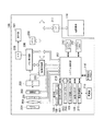
図2は、デジタルカメラ100の構成を示すブロック図である。なお、図1と同一の構成は、同一符号を付して適宜、その説明を省略する。
撮影レンズ200は、ズームレンズ、フォーカスレンズを含むレンズ群である。シャッター201は、絞り機能を備える。撮像部202は、光学像を電気信号に変換するCCDやCMOS素子等で構成される撮像素子である。A/D変換器203は、撮像部202から出力されるアナログ信号をデジタル信号に変換する。バリア204は、デジタルカメラ100の撮影レンズ200を覆うことにより、撮影レンズ200、シャッター201、撮像部202を含む撮像系の汚れや破損を防止する。
FIG. 2 is a block diagram showing the configuration of the digital camera 100. The same components as those in FIG. 1 are denoted by the same reference numerals, and the description thereof is omitted as appropriate.
The photographing lens 200 is a lens group including a zoom lens and a focus lens. The shutter 201 has an aperture function. The imaging unit 202 is an imaging element configured with a CCD or CMOS element that converts an optical image into an electrical signal. The A / D converter 203 converts the analog signal output from the imaging unit 202 into a digital signal. The barrier 204 covers the photographing lens 200 of the digital camera 100 to prevent the imaging system including the photographing lens 200, the shutter 201, and the imaging unit 202 from being soiled or damaged.

画像処理部205は、A/D変換器203からの画像データまたはメモリ制御部206からの画像データに対し所定の画素補間、縮小といったリサイズ処理や色変換処理を行う。また、画像処理部205では、撮像した画像データを用いて所定の演算処理が行われ、得られた演算結果に基づいてシステム制御部207が露光制御、測距制御を行う。この処理により、TTL(スルー・ザ・レンズ)方式のAF(オートフォーカス)処理、AE(自動露出)処理、EF(フラッシュプリ発光)処理が行われる。更に、画像処理部205では、撮像した画像データを用いて所定の演算処理を行い、得られた演算結果に基づいてTTL方式のAWB(オートホワイトバランス)処理も行っている。   The image processing unit 205 performs resizing processing and color conversion processing such as predetermined pixel interpolation and reduction on the image data from the A / D converter 203 or the image data from the memory control unit 206. The image processing unit 205 performs predetermined calculation processing using the captured image data, and the system control unit 207 performs exposure control and distance measurement control based on the obtained calculation result. By this processing, AF (autofocus) processing, AE (automatic exposure) processing, and EF (flash pre-emission) processing of the TTL (through the lens) method are performed. Further, the image processing unit 205 performs predetermined calculation processing using the captured image data, and also performs TTL AWB (auto white balance) processing based on the obtained calculation result.

A/D変換器203からの画像データは、画像処理部205およびメモリ制御部206を介してまたはメモリ制御部206を介してメモリ208に直接書き込まれる。メモリ208は、撮像部202によって得られA/D変換器203によりデジタルデータに変換された画像データや表示部101に表示するための画像データを格納する。メモリ208は、所定枚数の静止画像や所定時間の動画像および音声を格納するのに十分な記憶容量を備えている。また、メモリ208は、画像表示用のメモリ(ビデオメモリ)を兼ねている。   Image data from the A / D converter 203 is directly written into the memory 208 via the image processing unit 205 and the memory control unit 206 or via the memory control unit 206. The memory 208 stores image data obtained by the imaging unit 202 and converted into digital data by the A / D converter 203 and image data to be displayed on the display unit 101. The memory 208 has a storage capacity sufficient to store a predetermined number of still images, a moving image and sound for a predetermined time. The memory 208 also serves as an image display memory (video memory).

D/A変換器209は、メモリ208に格納されている表示用の画像データをアナログ信号に変換して表示部101に供給する。したがって、メモリ208に書き込まれた表示用の画像データは、D/A変換器209を介して表示部101により表示される。表示部101は、LCD等の表示器上にD/A変換器209からのアナログ信号に応じた表示を行う。A/D変換器203によって一度A/D変換されメモリ208に蓄積されたデジタル信号をD/A変換器209においてアナログ変換し、表示部101に逐次転送して表示することでスルー画像を表示でき、電子ビューファインダとして機能する。   The D / A converter 209 converts the display image data stored in the memory 208 into an analog signal and supplies the analog signal to the display unit 101. Therefore, the display image data written in the memory 208 is displayed on the display unit 101 via the D / A converter 209. The display unit 101 performs display in accordance with an analog signal from the D / A converter 209 on a display device such as an LCD. A digital signal once A / D converted by the A / D converter 203 and stored in the memory 208 is converted into an analog signal by the D / A converter 209, and sequentially transferred to the display unit 101 for display, thereby displaying a through image. Functions as an electronic viewfinder.

不揮発性メモリ210は、電気的に消去・記録可能なメモリであり、例えばEEPROM等が用いられる。不揮発性メモリ210には、システム制御部207の動作用の定数、プログラム等が記録される。このプログラムは、本実施形態の後述する各種フローチャートを実行するためのプログラムである。
システム制御部207は、デジタルカメラ100全体を制御する。システム制御部207は、表示制御手段、受付手段、設定手段および登録手段の一例に対応する。システム制御部207が不揮発性メモリ210に記録されたプログラムを実行することで、後述する本実施形態の各処理を実現する。システムメモリ211は、例えばRAMが用いられる。システムメモリ211には、システム制御部207の動作用の定数、変数、不揮発性メモリ210から読み出したプログラム等を展開する。また、システム制御部207は、メモリ208、D/A変換器209、表示部101等を制御することにより表示制御も行う。システムタイマ212は、各種制御に用いる時間や、内蔵された時計の時間を計測する計時部である。
The nonvolatile memory 210 is an electrically erasable / recordable memory, and for example, an EEPROM or the like is used. In the nonvolatile memory 210, constants, programs, and the like for operation of the system control unit 207 are recorded. This program is a program for executing various flowcharts described later in the present embodiment.
A system control unit 207 controls the entire digital camera 100. The system control unit 207 corresponds to an example of a display control unit, a reception unit, a setting unit, and a registration unit. The system control unit 207 executes the program recorded in the nonvolatile memory 210, thereby realizing each process of the present embodiment to be described later. For example, a RAM is used as the system memory 211. In the system memory 211, constants and variables for operation of the system control unit 207, programs read from the nonvolatile memory 210, and the like are expanded. The system control unit 207 also performs display control by controlling the memory 208, the D / A converter 209, the display unit 101, and the like. The system timer 212 is a timer unit that measures the time used for various controls and the time of a built-in clock.

操作部106、モード切替スイッチ103、第1シャッタースイッチ213、第2シャッタースイッチ214は、システム制御部207に各種の動作指示を入力するための操作手段である。
モード切替スイッチ103は、システム制御部207の動作モードを静止画記録モード、動画記録モード、再生モード等の何れかのモードに切替えることができる。静止画記録モードに含まれるモードとして、オート撮影モード、オートシーン判別モード、マニュアルモード、撮影シーン別の撮影設定となる各種シーンモード、プログラムAEモード、カスタムモード等がある。モード切替スイッチ103で、静止画記録モードに含まれる上述したモードの何れかに直接切替えることができる。あるいは、モード切替スイッチ103で静止画記録モードに一旦、切替えた後に、静止画記録モードに含まれる上述したモードの何れかに、他の操作部材を用いて切替えてもよい。同様に、動画記録モードにも複数のモードが含まれていてもよい。
The operation unit 106, the mode changeover switch 103, the first shutter switch 213, and the second shutter switch 214 are operation units for inputting various operation instructions to the system control unit 207.
The mode switch 103 can switch the operation mode of the system control unit 207 to any mode such as a still image recording mode, a moving image recording mode, and a reproduction mode. Modes included in the still image recording mode include an auto shooting mode, an auto scene discrimination mode, a manual mode, various scene modes for shooting settings for each shooting scene, a program AE mode, a custom mode, and the like. With the mode switch 103, it is possible to directly switch to any of the above-described modes included in the still image recording mode. Alternatively, after switching to the still image recording mode once with the mode switch 103, the mode may be switched to any of the above-described modes included in the still image recording mode using another operation member. Similarly, the moving image recording mode may include a plurality of modes.

第1シャッタースイッチ213は、デジタルカメラ100のシャッターボタン102の操作途中、いわゆる半押し(撮影準備指示)でオンとなり第1シャッタースイッチ信号SW1を発生させる。システム制御部207は、第1シャッタースイッチ信号SW1により、AF処理、AE処理、AWB処理、EF処理等の動作を開始する。
第2シャッタースイッチ214は、デジタルカメラ100のシャッターボタン102の操作完了、いわゆる全押し(撮影指示)でオンとなり第2シャッタースイッチ信号SW2を発生させる。システム制御部207は、第2シャッタースイッチ信号SW2により、撮像部202からの信号読み出しから記録媒体110に画像データを書き込むまでの一連の撮影処理の動作を開始する。
The first shutter switch 213 is turned on when the shutter button 102 of the digital camera 100 is being operated, so-called half-press (shooting preparation instruction), and generates the first shutter switch signal SW1. The system control unit 207 starts operations such as AF processing, AE processing, AWB processing, and EF processing in response to the first shutter switch signal SW1.
The second shutter switch 214 is turned on when the operation of the shutter button 102 of the digital camera 100 is completed, so-called full press (shooting instruction), and generates a second shutter switch signal SW2. In response to the second shutter switch signal SW2, the system control unit 207 starts a series of imaging processing operations from reading a signal from the imaging unit 202 to writing image data on the recording medium 110.

操作部106の各操作部材は、表示部101に表示される種々の機能アイコンを選択操作すること等により、場面毎に適宜機能が割り当てられ、各種機能ボタンとして作用する。機能ボタンとして例えば、終了ボタン、戻るボタン、画像送りボタン、ジャンプボタン、絞込みボタン、属性変更ボタン、INFOボタン等がある。例えば、メニューボタンが押されると各種設定が可能なメニュー画面が表示部101に表示される。ユーザは表示部101に表示されたメニュー画面と、左右方向キー、上下方向キーおよびSETボタンとを用いて直感的に各種設定を行うことができる。   Each operation member of the operation unit 106 is appropriately assigned a function for each scene by selecting and operating various function icons displayed on the display unit 101, and functions as various function buttons. Examples of the function buttons include an end button, a return button, an image advance button, a jump button, a narrow button, an attribute change button, and an INFO button. For example, when a menu button is pressed, a menu screen on which various settings can be made is displayed on the display unit 101. The user can make various settings intuitively using the menu screen displayed on the display unit 101, the left / right direction key, the up / down direction key, and the SET button.

コントローラホイール108は、操作部106に含まれる回転操作可能な操作部材である。コントローラホイール108は、方向キーと共に選択項目を指示するとき等に使用される。コントローラホイール108を回転操作すると、操作量に応じて電気的なパルス信号が発生し、システム制御部207はパルス信号に基づいてデジタルカメラ100の各部を制御する。システム制御部207は、このパルス信号によってコントローラホイール108が回転操作された角度や、何回転したか等を判定することができる。なお、コントローラホイール108は回転操作が検出できる操作部材であればどのようなものでもよい。例えば、ユーザの回転操作に応じてコントローラホイール108自体が回転してパルス信号を発生させるダイヤル操作部材であってもよい。また、タッチセンサよりなる操作部材で、コントローラホイール108自体は回転せず、コントローラホイール108上でのユーザの指の回転動作等を検出するものであってもよい(いわゆる、タッチホイール)。本実施形態では、コントローラホイール108をダイヤル操作が可能なダイヤル操作部材として説明する。   The controller wheel 108 is a rotatable operation member included in the operation unit 106. The controller wheel 108 is used when a selection item is designated together with a direction key. When the controller wheel 108 is rotated, an electrical pulse signal is generated according to the operation amount, and the system control unit 207 controls each part of the digital camera 100 based on the pulse signal. The system control unit 207 can determine the rotation angle of the controller wheel 108, how many rotations, and the like by this pulse signal. The controller wheel 108 may be any operation member that can detect a rotation operation. For example, the dial wheel may be a dial operation member that generates a pulse signal by rotating the controller wheel 108 in accordance with the rotation operation of the user. Further, an operation member made of a touch sensor may be used to detect a rotation operation of a user's finger on the controller wheel 108 without rotating the controller wheel 108 itself (so-called touch wheel). In the present embodiment, the controller wheel 108 will be described as a dial operation member capable of performing a dial operation.

電源制御部215は、電池検出回路、DC−DCコンバータ、通電するブロックを切替えるスイッチ回路等により構成され、電池の装着の有無、電池の種類、電池残量の検出を行う。また、電源制御部215は、その検出結果およびシステム制御部207の指示に基づいてDC−DCコンバータを制御し、必要な電圧を必要な期間、記録媒体110を含む各部へ供給する。電源部216は、アルカリ電池やリチウム電池等の一次電池やNiCd電池やNiMH電池、Li電池等の二次電池、ACアダプター等からなる。記録媒体I/F217は、撮像された画像を記録するためのメモリカード等であり、半導体メモリや磁気ディスク等から構成される。   The power control unit 215 includes a battery detection circuit, a DC-DC converter, a switch circuit that switches a block to be energized, and the like, and detects whether or not a battery is installed, the type of battery, and the remaining battery level. Further, the power control unit 215 controls the DC-DC converter based on the detection result and an instruction from the system control unit 207, and supplies a necessary voltage to each unit including the recording medium 110 for a necessary period. The power supply unit 216 includes a primary battery such as an alkaline battery or a lithium battery, a secondary battery such as a NiCd battery, a NiMH battery, or a Li battery, an AC adapter, or the like. The recording medium I / F 217 is a memory card or the like for recording a captured image, and includes a semiconductor memory, a magnetic disk, or the like.

また、操作部106の一つとして、表示部101に対する接触を検知可能なタッチパネル107を有する。タッチパネル107と表示部101とは一体的に構成することができる。例えば、光の透過率が表示部101の表示を妨げないように、タッチパネル107を表示部101の表示面の上層に取り付ける。そして、タッチパネル107における入力座標と、表示部101上の表示座標とを対応付けることで、あたかもユーザが表示部101上に表示された画面を直接的に操作可能であるかのようなGUIを構成することができる。
タッチパネル107には抵抗膜方式や静電容量方式、表面弾性波方式、赤外線方式、電磁誘導方式、画像認識方式、光センサ方式等の様々な方式のうち何れかを用いることができる。
In addition, as one of the operation units 106, a touch panel 107 that can detect contact with the display unit 101 is provided. The touch panel 107 and the display unit 101 can be configured integrally. For example, the touch panel 107 is attached to the upper layer of the display surface of the display unit 101 so that the light transmittance does not hinder the display of the display unit 101. Then, by associating the input coordinates on the touch panel 107 with the display coordinates on the display unit 101, a GUI is configured as if the user can directly operate the screen displayed on the display unit 101. be able to.
For the touch panel 107, any one of various methods such as a resistive film method, a capacitance method, a surface acoustic wave method, an infrared method, an electromagnetic induction method, an image recognition method, and an optical sensor method can be used.

システム制御部207はユーザによるタッチパネル107に対する以下の操作を検出できる。タッチパネル107を指やペンで触れたこと(タッチダウン操作)。タッチパネル107を指やペンで触れている状態であること(タッチオン操作)。タッチパネル107を指やペンで触れたまま移動していること(ムーブ操作)。タッチパネル107へ触れていた指やペンを離したこと(タッチアップ操作)。タッチパネル107に何も触れていない状態(タッチオフ操作)。   The system control unit 207 can detect the following operations on the touch panel 107 by the user. Touch panel 107 is touched with a finger or a pen (touchdown operation). The touch panel 107 is touched with a finger or a pen (touch-on operation). The touch panel 107 is moved while being touched with a finger or a pen (move operation). The finger or pen that has been touching the touch panel 107 is released (touch-up operation). A state where nothing is touched on the touch panel 107 (touch-off operation).

上述した操作やタッチパネル107上に指やペンが触れている位置座標は内部バス218を通じてシステム制御部207に通知される。システム制御部207は通知された情報に基づいてタッチパネル107上でどのような操作が行なわれたかを判定する。ムーブ操作については、システム制御部207はタッチパネル107上で移動する指やペンの移動方向を位置座標の変化に基づいて、タッチパネル107上の垂直成分・水平成分毎に判定できる。また、タッチパネル107上をタッチダウン操作から一定のムーブ操作を経てタッチアップ操作をしたとき、ストロークを描いたことになる。素早くストロークを描く操作をフリック操作と呼ぶ。フリック操作は、タッチパネル107上に指を触れたままある程度の距離だけ素早く動かして、そのまま離すといった操作であり、言い換えればタッチパネル107上を指ではじくように素早くなぞる操作である。システム制御部207は所定距離以上を所定速度以上でムーブ操作されたことを検出し、そのままタッチアップ操作を検出するとフリック操作が行なわれたと判定する。また、システム制御部207は所定距離以上を所定速度未満でムーブ操作したことが検出された場合はドラッグ操作が行なわれたと判定する。   The system controller 207 is notified through the internal bus 218 of the above-described operations and the position coordinates where the finger or pen touches the touch panel 107. The system control unit 207 determines what operation has been performed on the touch panel 107 based on the notified information. Regarding the move operation, the system control unit 207 can determine the moving direction of the finger or pen moving on the touch panel 107 for each vertical component / horizontal component on the touch panel 107 based on the change of the position coordinates. Further, when a touch-up operation is performed on the touch panel 107 through a certain move operation from a touch-down operation, a stroke is drawn. The operation of drawing a stroke quickly is called a flick operation. The flick operation is an operation of quickly moving a certain distance while touching the finger on the touch panel 107 and releasing it, in other words, an operation of quickly tracing the touch panel 107 with a finger. The system control unit 207 detects that a move operation has been performed at a predetermined speed or more at a predetermined speed or more, and determines that a flick operation has been performed if a touch-up operation is detected as it is. Further, the system control unit 207 determines that the drag operation has been performed when it is detected that the move operation has been performed at a predetermined distance or more and less than a predetermined speed.

以下、図面を参照して、デジタルカメラ100の撮影設定に関する設定値を設定する方法について説明する。ここでは、デジタルカメラ100の撮影設定としてISO感度を取り上げて説明する。
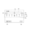
図3は、表示部101に表示されるISO感度値の設定を行うための設定画面を示す図である。図3に示す画面には、情報表示301、スケール302、左方向のタッチボタン303、右方向のタッチボタン304、オートタッチボタン305、終了タッチボタン306等が表示される。ユーザがスケール302内に表示されるISO感度値の何れかを選択することで、選択されたISO感度値が設定される。
Hereinafter, with reference to the drawings, a method for setting setting values relating to shooting settings of the digital camera 100 will be described. Here, ISO sensitivity will be described as a shooting setting of the digital camera 100.
FIG. 3 is a diagram showing a setting screen for setting the ISO sensitivity value displayed on the display unit 101. An information display 301, a scale 302, a left touch button 303, a right touch button 304, an auto touch button 305, an end touch button 306, etc. are displayed on the screen shown in FIG. When the user selects one of the ISO sensitivity values displayed in the scale 302, the selected ISO sensitivity value is set.

情報表示301は、スケール302に表示されるISO感度値のうちユーザにより選択されたISO感度値を表示している。
スケール302は、複数のISO感度値を並べて表示している。ここで、スケール302には、デジタルカメラ100に設定可能なISO感度値(設定候補)のうち一部の範囲の複数のISO感度値302aが一定の間隔をあけて左右方向に並べて表示される。また、スケール302は、各ISO感度値302aに対応する目盛302bが、一定の間隔をあけて左右方向に並べて表示される。更に、スケール302では、選択されたISO感度値に対応する目盛にカーソル302cが表示される。したがって、ユーザは選択しているISO感度値を簡単に確認できる。また、スケール302では、表示するISO感度値の範囲を、選択されたISO感度値とその近隣値を含む範囲にして表示される。したがって、ユーザは、選択したISO感度値とその近隣値を簡単に確認できる。
The information display 301 displays the ISO sensitivity value selected by the user from the ISO sensitivity values displayed on the scale 302.
The scale 302 displays a plurality of ISO sensitivity values side by side. Here, on the scale 302, a plurality of ISO sensitivity values 302a in a part of the ISO sensitivity values (setting candidates) that can be set in the digital camera 100 are displayed side by side with a certain interval. The scale 302 displays scales 302b corresponding to the ISO sensitivity values 302a side by side in a horizontal direction with a certain interval. Further, on the scale 302, a cursor 302c is displayed on a scale corresponding to the selected ISO sensitivity value. Therefore, the user can easily confirm the selected ISO sensitivity value. On the scale 302, the range of the ISO sensitivity value to be displayed is displayed as a range including the selected ISO sensitivity value and its neighboring values. Therefore, the user can easily confirm the selected ISO sensitivity value and its neighboring values.

ユーザはコントローラホイール108のダイヤル操作(以下、ダイヤル操作という)や左右方向キーの操作により、異なるISO感度値を選択することができる。システム制御部207は、操作部106による操作量に応じて、異なるISO感度値を選択状態にして表示する。具体的には、システム制御部207は、スケール302の中央に、選択されたISO感度値を表示すると共に、選択されたISO感度値に対応する目盛にカーソル302cを表示する。更に、システム制御部207は、選択されたISO感度値の数値を情報表示301として表示する。
また、タッチパネル107によるタッチ操作が有効である場合、ユーザはスケール302内でムーブ操作を行うことができる。システム制御部207は、ムーブ操作による移動量に応じて、スケール302内に表示するISO感度値を変更して表示する。
また、ユーザはスケール302内の何れかのISO感度値に対してタッチ操作を行うことができる。システム制御部207は、タッチ操作されたISO感度値を、ユーザにより選択されたISO感度値として選択状態にして表示する。更に、システム制御部207は、スケール302内に表示するISO感度値の範囲を、選択されたISO感度値とその近隣値を含む範囲に変更する。
The user can select a different ISO sensitivity value by a dial operation on the controller wheel 108 (hereinafter referred to as a dial operation) or a left / right direction key operation. The system control unit 207 displays different ISO sensitivity values in a selected state according to the operation amount by the operation unit 106. Specifically, the system control unit 207 displays the selected ISO sensitivity value at the center of the scale 302 and displays the cursor 302c on the scale corresponding to the selected ISO sensitivity value. Further, the system control unit 207 displays the selected ISO sensitivity value as the information display 301.
Further, when the touch operation using the touch panel 107 is valid, the user can perform a move operation within the scale 302. The system control unit 207 changes and displays the ISO sensitivity value displayed in the scale 302 according to the movement amount by the move operation.
The user can perform a touch operation on any ISO sensitivity value in the scale 302. The system control unit 207 displays the touched ISO sensitivity value in a selected state as the ISO sensitivity value selected by the user. Further, the system control unit 207 changes the range of the ISO sensitivity value displayed in the scale 302 to a range including the selected ISO sensitivity value and its neighboring values.

このように、スケール302内に一度に表示するISO感度値の範囲は、設定可能なISO感度値の全ての範囲ではなく、現在選択されているISO感度値の周辺の一部である。したがって、設定可能なISO感度値の全範囲を表示する場合に比べて、ISO感度値の間隔や、ISO感度値に対応する目盛の間隔を大きく表示することができる。例えば、ISO感度値の間隔およびISO感度値に対応する目盛の間隔が狭いと、タッチ操作による正確な操作が困難になってしまう。しかしながら、本実施形態のようにスケール302内に一度に表示するISO感度値の範囲を一部に絞ることでISO感度値の間隔および目盛の間隔を大きくすることができ、ユーザはタッチ操作によって所望するISO感度値を正確に選択することができる。   As described above, the range of ISO sensitivity values displayed at once in the scale 302 is not the entire range of ISO sensitivity values that can be set, but a part around the currently selected ISO sensitivity value. Therefore, compared to displaying the entire range of ISO sensitivity values that can be set, the intervals of ISO sensitivity values and the intervals of scales corresponding to the ISO sensitivity values can be displayed larger. For example, when the interval between the ISO sensitivity values and the interval between the scales corresponding to the ISO sensitivity values are narrow, an accurate operation by a touch operation becomes difficult. However, the ISO sensitivity value interval and the scale interval can be increased by narrowing the range of ISO sensitivity values displayed at a time within the scale 302 as in the present embodiment, and the user can perform a desired operation by touch operation. The ISO sensitivity value to be selected can be accurately selected.

左方向のタッチボタン303は設定画面の左側に表示され、右方向のタッチボタン304は設定画面の右側に表示される。ユーザは、タッチボタン303、304に対するタッチ操作を行うことができる。システム制御部207は、タッチボタン303、304に対するタッチ操作に応じて、ダイヤル操作や左右方向キーの操作と同様の処理を行う。具体的には、システム制御部207は、タッチボタン303、304に対する1回のタッチ操作に応じて、現在選択されているISO感度値からタッチボタン303、304に対応する方向に隣接するISO感度値を選択状態にして表示する。なお、現在選択されているISO感度値がスケール302内の端に位置するISO感度値の場合にはISO感度値を変更できず、ユーザによるタッチボタン303、304のタッチ操作が無効になる場合がある。この場合には、システム制御部207はISO感度値を変更することができない側のタッチボタン303、304を無効表示する。無効表示とは、ユーザに対してボタンが無効であることを識別させるための表示である。無効表示として、例えばボタン内をグレーアウトにして表示する。一方、有効表示とは、ユーザに対してボタンが有効であることを識別させるための表示である。有効表示として、例えばボタン内を白色等にして表示する。
なお、タッチ操作が無効の場合、システム制御部207は、タッチボタン303、304をタッチボタンではなく方向キーの操作ガイド表示とする。
The left touch button 303 is displayed on the left side of the setting screen, and the right touch button 304 is displayed on the right side of the setting screen. The user can perform a touch operation on the touch buttons 303 and 304. The system control unit 207 performs the same processing as the dial operation and the left / right direction key operation according to the touch operation on the touch buttons 303 and 304. Specifically, in response to a single touch operation on the touch buttons 303 and 304, the system control unit 207 determines the ISO sensitivity value adjacent in the direction corresponding to the touch buttons 303 and 304 from the currently selected ISO sensitivity value. Is displayed in the selected state. If the currently selected ISO sensitivity value is an ISO sensitivity value located at the end of the scale 302, the ISO sensitivity value cannot be changed, and the touch operation of the touch buttons 303 and 304 by the user may be invalidated. is there. In this case, the system control unit 207 displays invalid the touch buttons 303 and 304 on the side where the ISO sensitivity value cannot be changed. The invalid display is a display for identifying to the user that the button is invalid. As an invalid display, for example, the button is displayed in gray out. On the other hand, the valid display is a display for identifying to the user that the button is valid. As an effective display, for example, the button is displayed in white or the like.
When the touch operation is invalid, the system control unit 207 displays the touch buttons 303 and 304 as direction key operation guide displays instead of the touch buttons.

オートタッチボタン305は、ISO感度値をオートに設定するためのボタンである。ユーザは、オートタッチボタン305に対するタッチ操作を行うことができる。システム制御部207は、オートタッチボタン305に対するタッチ操作に応じて、スケール302内に表示されるISO感度値のうちオート(AUTO)を選択状態にして表示すると共に、ISO感度値をオートに設定する。ここで、ISO感度値をオートに設定した場合、システム制御部207は自らが最適なISO感度値を決定する。すなわち、ISO感度値が自動的に決定されるので、ユーザはISO感度値を選択する必要がない。
このとき、システム制御部207はユーザに対してISO感度値がオートに変更されたことを明示するため、スケール移動のアニメーション表示を行う。スケール移動のアニメーション表示とは、スケール302内に表示するISO感度値の範囲を、現在の範囲から最終的に左端に位置するオートを含む範囲となるように徐々に移動させる表示をいう。すなわち、スケール302を右側に移動するスクロールアニメーションである。なお、この設定画面においてユーザにより操作部106のINFOボタンの操作が行われた場合、システム制御部207はオートタッチボタン305のタッチ操作と同様の処理を行う。以降のオートタッチボタン305に関する記載は、操作部106のINFOボタンを操作することでも実施可能となる。なお、タッチ操作が無効である場合、オートタッチボタン305は、同様の操作が割り当てられる操作部106のどの操作部材になっているかの操作ガイド表示となる。
The auto touch button 305 is a button for setting the ISO sensitivity value to auto. The user can perform a touch operation on the auto touch button 305. In response to a touch operation on the auto touch button 305, the system control unit 207 displays the ISO sensitivity value displayed in the scale 302 with auto (AUTO) selected, and sets the ISO sensitivity value to auto. . Here, when the ISO sensitivity value is set to auto, the system control unit 207 determines the optimum ISO sensitivity value by itself. That is, since the ISO sensitivity value is automatically determined, the user does not need to select the ISO sensitivity value.
At this time, the system control unit 207 displays a scale movement animation to clearly indicate to the user that the ISO sensitivity value has been changed to auto. The scale movement animation display refers to a display in which the range of ISO sensitivity values displayed in the scale 302 is gradually moved from the current range to the range including the auto that is finally located at the left end. That is, it is a scroll animation that moves the scale 302 to the right. Note that when the user operates the INFO button of the operation unit 106 on this setting screen, the system control unit 207 performs processing similar to the touch operation of the auto touch button 305. The following description regarding the auto touch button 305 can also be implemented by operating the INFO button of the operation unit 106. When the touch operation is invalid, the auto touch button 305 becomes an operation guide display indicating which operation member of the operation unit 106 to which a similar operation is assigned.

終了タッチボタン306は、設定画面を終了させるためのボタンである。ユーザは、終了タッチボタン306に対するタッチ操作を行うことができる。システム制御部207は、終了タッチボタン306に対するタッチ操作に応じて、ISO感度値の設定を行う設定画面を終了する。   The end touch button 306 is a button for ending the setting screen. The user can perform a touch operation on the end touch button 306. In response to the touch operation on the end touch button 306, the system control unit 207 ends the setting screen for setting the ISO sensitivity value.

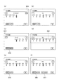
図4は、上述したISO感度値の設定画面において、ISO感度値を変更した場合の表示例を示す図である。
図4(a)は、スケール302が右端になった場合の設定画面である。
図4(a)に示す右端のISO感度値は、現在のデジタルカメラ100の設定状態において設定可能なISO感度値のうち最も右端に位置するもの(最大のISO感度値)である。ここでは、拡張ISO感度の範囲まで設定できる状態であるため、ISO感度値H(25600)が選択されている。この表示状態では、左端に位置するオートは表示されない。また、右方向のタッチボタン304は無効表示となる。
FIG. 4 is a diagram showing a display example when the ISO sensitivity value is changed on the ISO sensitivity value setting screen described above.
FIG. 4A shows a setting screen when the scale 302 is at the right end.
The ISO sensitivity value at the right end shown in FIG. 4A is the most ISO sensitivity value that can be set in the current setting state of the digital camera 100 (maximum ISO sensitivity value). Here, the ISO sensitivity value H (25600) is selected because it can be set up to the range of the extended ISO sensitivity. In this display state, the auto located at the left end is not displayed. The right touch button 304 is disabled.

図4(b)は、スケール302内に左端が表示されている場合の設定画面である。
図4(b)では、現在選択されているISO感度値の近隣値が表示されると共に、左端に位置するオートも含めて表示される。なお、デジタルカメラ100の設定状態によってはISO感度値をオートに設定できず、無効になる場合がある。この場合、オートタッチボタン305は無効表示となる。また、オートに設定できない場合、左端のISO感度値は、現在のデジタルカメラ100の設定状態において設定可能なISO感度値のうち最も左端に位置するもの(最小のISO感度値)である。
FIG. 4B is a setting screen when the left end is displayed in the scale 302.
In FIG. 4B, the neighborhood value of the currently selected ISO sensitivity value is displayed, and the auto value located at the left end is also displayed. Depending on the setting state of the digital camera 100, the ISO sensitivity value cannot be set to auto and may become invalid. In this case, the auto touch button 305 is disabled. If the auto sensitivity cannot be set, the leftmost ISO sensitivity value is the leftmost ISO sensitivity value that can be set in the current setting state of the digital camera 100 (minimum ISO sensitivity value).

図4(c)は、スケール302が左端になった場合の設定画面である。
図4(c)では、選択されているISO感度値がオートであることを表示している。この場合、オートタッチボタン305および左方向のタッチボタン303は無効表示となる。
FIG. 4C shows a setting screen when the scale 302 is at the left end.
In FIG. 4C, it is displayed that the selected ISO sensitivity value is auto. In this case, the auto touch button 305 and the left touch button 303 are disabled.

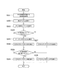
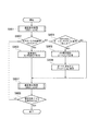
次に、ISO感度値の設定画面の画面表示処理について図5のフローチャートを参照して説明する。なお、図5を含む以下のフローチャートは、システム制御部207が不揮発性メモリ210に記録されたプログラムをシステムメモリ211に展開して実行することにより実現する。
まず、ステップS501では、システム制御部207は、画面表示処理を開始すると、不揮発性メモリ210からISO感度値とISO感度値の設定に関連するデジタルカメラ100の設定値とを取得する。
ステップS502では、システム制御部207は、表示部101に図3に示すような表示アイテムを表示する。この処理は、表示制御手段による処理の一例に対応する。
ステップS503では、システム制御部207は、ステップS501において取得したISO感度値が選択状態になるように、ISO感度値の情報表示301とスケール302とを表示する。すなわち、システム制御部207は、取得したISO感度値を情報表示301として表示し、スケール302の中央に取得したISO感度値を表示すると共に、取得したISO感度値に対応する目盛にカーソル302cを表示する。
Next, screen display processing of the ISO sensitivity value setting screen will be described with reference to the flowchart of FIG. The following flowchart including FIG. 5 is realized by the system control unit 207 expanding and executing the program recorded in the nonvolatile memory 210 in the system memory 211.
First, in step S501, the system control unit 207 acquires the ISO sensitivity value and the setting value of the digital camera 100 related to the setting of the ISO sensitivity value from the nonvolatile memory 210 when the screen display process is started.
In step S <b> 502, the system control unit 207 displays a display item as illustrated in FIG. 3 on the display unit 101. This processing corresponds to an example of processing by the display control unit.
In step S503, the system control unit 207 displays the ISO sensitivity value information display 301 and the scale 302 so that the ISO sensitivity value acquired in step S501 is selected. That is, the system control unit 207 displays the acquired ISO sensitivity value as the information display 301, displays the acquired ISO sensitivity value at the center of the scale 302, and displays the cursor 302c on the scale corresponding to the acquired ISO sensitivity value. To do.

ステップS504では、システム制御部207は、ステップS501において取得したISO感度値がオートであるか否かを判定する。オートである場合にはステップS505に進み、オートではない場合にはステップS507に進む。
ステップS505では、システム制御部207は、オートタッチボタン305を無効表示にする。
ステップS506では、システム制御部207は、左方向のタッチボタン303を無効表示にする。このとき、システム制御部207は、左方向のタッチボタン303のタッチ操作、ダイヤル操作および左方向キーの操作を無効にする。
ステップS504からステップS507に進んだ場合、システム制御部207は、左方向のタッチボタン303を有効表示にし、左方向のタッチボタン303の操作、ダイヤル操作および左方向キーの操作を有効にする。
In step S504, the system control unit 207 determines whether or not the ISO sensitivity value acquired in step S501 is auto. If it is auto, the process proceeds to step S505, and if it is not auto, the process proceeds to step S507.
In step S505, the system control unit 207 disables the auto touch button 305.
In step S506, the system control unit 207 disables the left touch button 303. At this time, the system control unit 207 invalidates the touch operation of the left touch button 303, the dial operation, and the left key operation.
When the process proceeds from step S504 to step S507, the system control unit 207 enables the left touch button 303 to be effectively displayed, and enables the operation of the left touch button 303, the dial operation, and the left key operation.

ステップS508では、システム制御部207は、ステップS501において取得したISO感度値が現在とりうるISO感度値の最大値であるか否かを判定する。最大値である場合にはステップS509に進み、最大値ではない場合にはステップS510に進む。
ステップS509では、システム制御部207は、右方向のタッチボタン304を無効表示にする。また、システム制御部207は、右方向のタッチボタン304のタッチ操作、ダイヤル操作および右方向キーの操作を無効にする。
一方、ステップS510では、システム制御部207は、右方向のタッチボタン304を有効表示にし、右方向のタッチボタン304、ダイヤル操作および右方向キーの操作を有効にする。
In step S508, the system control unit 207 determines whether or not the ISO sensitivity value acquired in step S501 is the maximum ISO sensitivity value that can be currently taken. If it is the maximum value, the process proceeds to step S509, and if it is not the maximum value, the process proceeds to step S510.
In step S509, the system control unit 207 disables the right touch button 304. Further, the system control unit 207 invalidates the touch operation of the right touch button 304, the dial operation, and the right key operation.
On the other hand, in step S510, the system control unit 207 activates the right touch button 304 and validates the right touch button 304, dial operation, and right key operation.

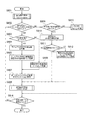
次に、ISO感度値の設定画面におけるISO感度値の変更処理について図6のフローチャートを参照して説明する。ここでは、システム制御部207が操作部106を介した操作を取得することで、表示部101に表示する設定画面を変更する。   Next, the ISO sensitivity value changing process on the ISO sensitivity value setting screen will be described with reference to the flowchart of FIG. Here, the setting screen displayed on the display unit 101 is changed by the system control unit 207 acquiring an operation via the operation unit 106.

まず、ステップS601では、システム制御部207は、画面表示処理を行う。ステップS601の画面表示処理は、上述したステップS501〜ステップS510の処理である。画面表示処理が完了し、例えばISO感度値が160であった場合には、図4(b)に示す画面表示になる。
ステップS602では、システム制御部207は、ユーザによるコントローラホイール108、左右方向キー、左方向のタッチボタン303、右方向のタッチボタン304またはスケール302に対する何れかの操作があったか否かを判定する。すなわち、システム制御部207は、ユーザによる右方向操作または左方向操作があったか否かを判定する。この処理は、受付手段による処理の一例に対応する。右方向操作または左方向操作があった場合にはステップS603に進み、右方向操作または左方向操作がない場合にはステップS604に進む。
First, in step S601, the system control unit 207 performs screen display processing. The screen display process in step S601 is the process in steps S501 to S510 described above. When the screen display process is completed and, for example, the ISO sensitivity value is 160, the screen display shown in FIG.
In step S <b> 602, the system control unit 207 determines whether the user has performed any operation on the controller wheel 108, the left / right direction key, the left direction touch button 303, the right direction touch button 304, or the scale 302. That is, the system control unit 207 determines whether there is a right direction operation or a left direction operation by the user. This processing corresponds to an example of processing by the receiving unit. If there is a right direction operation or a left direction operation, the process proceeds to step S603, and if there is no right direction operation or a left direction operation, the process proceeds to step S604.

ステップS603では、システム制御部207は、コントローラホイール108、左右方向キー、左方向のタッチボタン303、右方向のタッチボタン304、スケール302の操作方向と操作量の何れかの操作を取得する。システム制御部207は、取得した操作に応じて、ユーザにより選択されたISO感度値を不揮発性メモリ210に記録する。例えば、システム制御部207が操作部106の左方向キーによる1回の操作を取得した場合、スケール302内で選択されているISO感度値の1つ左側に位置するISO感度値を記録する。また、システム制御部207が操作部106の右方向キーによる1回の操作を取得した場合、スケール302内で選択されているISO感度値の1つ右側に位置するISO感度値を記録する。システム制御部207は、選択されたISO感度値を不揮発性メモリ210に記録することで、ISO感度値を設定する。この処理は、設定手段による処理の一例に対応する。
一方、ステップ604では、システム制御部207は、ユーザによる操作部106のINFOボタンまたはオートタッチボタン305に対する操作があったか否かを判定する。操作があった場合にはステップS605に進み、操作がない場合にはステップS607に進む。
In step S <b> 603, the system control unit 207 acquires any one of the operation direction and the operation amount of the controller wheel 108, the left / right direction key, the left direction touch button 303, the right direction touch button 304, and the scale 302. The system control unit 207 records the ISO sensitivity value selected by the user in the nonvolatile memory 210 in accordance with the acquired operation. For example, when the system control unit 207 acquires a single operation with the left direction key of the operation unit 106, the ISO sensitivity value located on the left side of the ISO sensitivity value selected in the scale 302 is recorded. In addition, when the system control unit 207 acquires a single operation using the right direction key of the operation unit 106, the ISO sensitivity value positioned to the right of the ISO sensitivity value selected in the scale 302 is recorded. The system control unit 207 sets the ISO sensitivity value by recording the selected ISO sensitivity value in the nonvolatile memory 210. This processing corresponds to an example of processing by the setting unit.
On the other hand, in step 604, the system control unit 207 determines whether or not the user has operated the INFO button or the auto touch button 305 of the operation unit 106. If there is an operation, the process proceeds to step S605, and if there is no operation, the process proceeds to step S607.

ステップS605では、システム制御部207は、ISO感度値をオートとして不揮発性メモリ210に記録することで、ISO感度値を設定する。
ステップS606では、システム制御部207は、スケール302内で選択されているISO感度値をオートに変更するアニメーション表示を行い、ユーザに対してISO感度値がオートに設定されたことを識別可能に明示する。このようにアニメーション表示を挟むことでISO感度値が変更されたことを強調でき、ユーザにISO感度がオートに設定されたことを十分に認識させることができる。
In step S605, the system control unit 207 sets the ISO sensitivity value by recording the ISO sensitivity value as auto in the nonvolatile memory 210.
In step S606, the system control unit 207 displays an animation to change the ISO sensitivity value selected in the scale 302 to auto, and clearly indicates to the user that the ISO sensitivity value has been set to auto. To do. Thus, by sandwiching the animation display, it can be emphasized that the ISO sensitivity value has been changed, and the user can fully recognize that the ISO sensitivity has been set to auto.

ステップS607では、システム制御部207は、ISO感度値の設定画面の表示アイテムを更新する画面表示処理を行う。この処理は、上述したステップS503〜ステップS510と同様の処理である。ステップS607の画面表示処理が完了し、ISO感度値がオートに更新された場合には、図4(c)に示す設定画面になる。
ステップS608では、システム制御部207は、ISO感度値を設定する設定画面を終了する操作が行われたか否かを判定する。設定画面を終了する操作が行われた場合にはシステム制御部207は設定画面を終了し、設定画面を終了する操作が行われていない場合にはステップS602に戻る。
In step S <b> 607, the system control unit 207 performs screen display processing for updating the display item on the ISO sensitivity value setting screen. This process is the same as the above-described steps S503 to S510. When the screen display process in step S607 is completed and the ISO sensitivity value is updated to auto, the setting screen shown in FIG.
In step S608, the system control unit 207 determines whether an operation for ending the setting screen for setting the ISO sensitivity value has been performed. When the operation for ending the setting screen is performed, the system control unit 207 ends the setting screen, and when the operation for ending the setting screen is not performed, the process returns to step S602.

本実施形態では、上述したステップS604およびステップS605の処理を行うことで、ISO感度値を1回の操作でオートに設定することができる。例えば、ステップS602、ステップS603の処理のみでは1回の操作につきスケール302内のISO感度値を1つずつ動かす操作となってしまう。したがって、例えば図4(a)のように右端から図4(c)の左端に位置するオートまで変更するには手数が掛かってしまう。
一方、本実施形態では、ISO感度値を1つずつ動かす手数を省略することができ、所望するISO感度値、ここではオートに素早く設定することができるので、ISO感度値を設定するときの操作性を向上させることができる。
In the present embodiment, the ISO sensitivity value can be set to auto by a single operation by performing the processing in steps S604 and S605 described above. For example, only the processing in steps S602 and S603 results in an operation of moving the ISO sensitivity values in the scale 302 one by one for each operation. Therefore, for example, as shown in FIG. 4A, it takes time to change from the right end to the auto positioned at the left end of FIG. 4C.
On the other hand, in this embodiment, it is possible to omit the step of moving the ISO sensitivity value one by one, and it is possible to quickly set the desired ISO sensitivity value, here, auto. Can be improved.

次に、スケール302内の表示に応じてオートタッチボタン305を表示または非表示にする表示処理について図7のフローチャートを参照して説明する。
この処理は、上述したステップS601〜ステップS607の後、ステップS608の前に行われる。
ステップS701では、システム制御部207は、ステップS603またはステップS605において不揮発性メモリ210に記録されているISO感度値、すなわち現在設定されているISO感度値を取得する。
ステップS702では、システム制御部207は、現在のデジタルカメラ100の設定状態に基づいてオートをスケール302内に表示できるか否かを判定する。このように、オートを表示できるか否かを判定するのは、例えば同じISO感度値であってもISO感度値を拡張する設定を有効にしている場合、スケール302内の左端に位置するオートを表示できる場合とできない場合とがあるためである。スケール302内にオートを表示できる場合にはステップS703に進み、オートを表示できない場合にはステップS704に進む。
Next, display processing for displaying or hiding the auto touch button 305 according to the display in the scale 302 will be described with reference to the flowchart of FIG.
This process is performed after step S601 to step S607 described above and before step S608.
In step S701, the system control unit 207 acquires the ISO sensitivity value recorded in the nonvolatile memory 210 in step S603 or step S605, that is, the currently set ISO sensitivity value.
In step S <b> 702, the system control unit 207 determines whether auto can be displayed in the scale 302 based on the current setting state of the digital camera 100. In this way, whether or not auto can be displayed is determined, for example, by setting the auto at the left end in the scale 302 when the setting for extending the ISO sensitivity value is enabled even if the ISO sensitivity value is the same. This is because there are cases where it can be displayed and cases where it cannot be displayed. If auto can be displayed in the scale 302, the process proceeds to step S703, and if auto cannot be displayed, the process proceeds to step S704.

ステップS703では、システム制御部207は図4(d)に示すようにオートタッチボタン305を非表示にする。図4(d)では、スケール302内にオートを表示できる場合を示している。
一方、ステップS704では、システム制御部207は、既に設定画面内にオートタッチボタン305が表示されているか否かを判定する。表示されていない場合にはステップS705に進み、システム制御部207は、図4(e)に示すようにオートタッチボタン305を表示し、表示されている場合には処理を終了する。
In step S703, the system control unit 207 hides the auto touch button 305 as shown in FIG. FIG. 4D shows a case where auto can be displayed in the scale 302.
On the other hand, in step S704, the system control unit 207 determines whether or not the auto touch button 305 is already displayed in the setting screen. If it is not displayed, the process proceeds to step S705, and the system control unit 207 displays the auto touch button 305 as shown in FIG. 4E. If it is displayed, the process ends.

上述したステップS608では図4(c)に示す設定画面のようにオートタッチボタン305を無効表示にしたが、ここではスケール302内にオートが表示される場合には、システム制御部207はオートタッチボタン305を非表示にする。このような処理によって、1回の操作でオートに設定できるようにしつつも、オートタッチボタン305を非表示にすることで、自然画や撮影時のスルー画像上に設定画面を表示した場合でも、ユーザは後側の画像をより広く視認できる。特に、常にスルー画像を表示させるミラーレスタイプ等のデジタルカメラに適用した場合、ユーザは撮影対象の広い視認が可能になる。   In step S608 described above, the auto touch button 305 is disabled as shown in the setting screen shown in FIG. 4C. However, when auto is displayed in the scale 302, the system control unit 207 performs auto touch. The button 305 is hidden. Even if the setting screen is displayed on a natural image or a through image at the time of shooting by disabling the auto touch button 305 while enabling the setting to auto by a single operation by such processing, The user can visually recognize the rear image more widely. In particular, when applied to a digital camera such as a mirrorless type that always displays a through image, the user can view a wide range of objects to be photographed.

次に、オートタッチボタン305を用いてISO感度値のオートとマニュアルとの切替処理について図8のフローチャートを参照して説明する。なお、上述の図4(c)の説明では、選択されているISO感度値がオートである場合にはオートタッチボタン305を無効表示するものとして説明したが、ここではISO感度値がオートであってもオートタッチボタン305を有効表示し、タッチ操作を有効にする。
まず、ステップS801では、システム制御部207は、画面表示処理を行う。ステップS801の画面表示処理は、上述したステップS501〜ステップS510の処理である。
ステップS802では、システム制御部207は、ユーザによる操作部106のINFOボタンまたはオートタッチボタン305に対する操作があったか否かを判定する。操作があった場合にはステップS803に進み、操作がない場合にはステップS809に進む。
ステップS803では、システム制御部207は、現在設定されているISO感度値がオートであるか否かを判定する。オートの場合にはステップS804に進み、オートではない場合にはステップS806に進む。
Next, switching processing between ISO and manual ISO sensitivity values using the auto touch button 305 will be described with reference to the flowchart of FIG. In the description of FIG. 4C described above, the auto touch button 305 is invalidly displayed when the selected ISO sensitivity value is auto. However, here, the ISO sensitivity value is auto. Even if the auto touch button 305 is displayed effectively, the touch operation is enabled.
First, in step S801, the system control unit 207 performs screen display processing. The screen display process in step S801 is the process in steps S501 to S510 described above.
In step S <b> 802, the system control unit 207 determines whether the user has operated the INFO button or the auto touch button 305 of the operation unit 106. If there is an operation, the process proceeds to step S803, and if there is no operation, the process proceeds to step S809.
In step S803, the system control unit 207 determines whether the currently set ISO sensitivity value is auto. If it is auto, the process proceeds to step S804. If it is not auto, the process proceeds to step S806.

ステップS804では、システム制御部207は、マニュアル時のISO感度値を不揮発性メモリ210から取得する。ここで、マニュアル時のISO感度値とは、ユーザによる操作を介して設定したときのISO感度値であり、後述するステップS812において不揮発性メモリ210に記録されるISO感度値である。
ステップS805では、システム制御部207は、取得したマニュアル時のISO感度値を、現在のISO感度値として不揮発性メモリ210に記録する。
ステップS803からステップS806に進んだ場合、システム制御部207は、現在のISO感度値をオートにして不揮発性メモリ210に記録する。このようにしてステップS803〜ステップS806においてISO感度値のマニュアルとオートとの切替えが行われる。
In step S804, the system control unit 207 obtains the ISO sensitivity value at the time of manual operation from the nonvolatile memory 210. Here, the manual ISO sensitivity value is an ISO sensitivity value set through an operation by a user, and is an ISO sensitivity value recorded in the nonvolatile memory 210 in step S812 to be described later.
In step S805, the system control unit 207 records the acquired manual ISO sensitivity value in the nonvolatile memory 210 as the current ISO sensitivity value.
When the process proceeds from step S803 to step S806, the system control unit 207 sets the current ISO sensitivity value to auto and records it in the nonvolatile memory 210. In this manner, the ISO sensitivity value is switched between manual and auto in steps S803 to S806.

ステップS807では、システム制御部207は、スケール302内で選択されているISO感度値を不揮発性メモリ210に記録されたISO感度値に変更するアニメーション表示を行う。この処理により、ユーザに対してオートとマニュアルとが切替えられたことを識別可能に明示する。
ステップS808では、システム制御部207は、ISO感度値の設定画面の表示アイテムを更新する画面表示処理を行う。この処理は、上述したステップS503〜ステップS510と同様の処理である。
In step S <b> 807, the system control unit 207 performs animation display for changing the ISO sensitivity value selected in the scale 302 to the ISO sensitivity value recorded in the nonvolatile memory 210. By this processing, it is clearly shown to the user that the switching between auto and manual is possible.
In step S808, the system control unit 207 performs screen display processing for updating the display item on the ISO sensitivity value setting screen. This process is the same as the above-described steps S503 to S510.

ステップS802からステップS809に進んだ場合、システム制御部207は、右方向操作または左方向操作があったか否かを判定する。操作があった場合にはステップS810に進み、操作がない場合にはステップS813に進む。
ステップS810では、システム制御部207は、取得した操作に応じて、ユーザにより選択されたISO感度値を不揮発性メモリ210に記録する。例えばISO感度値にオートが設定されている状態で、右方向操作があった場合には、現在とりうるISO感度値の最小値が不揮発性メモリ210に記録される。ステップS810の処理は、ステップS603の処理と同様である。
ステップS811では、システム制御部207は、ISO感度値がオートか否かを判定する。オートの場合にはステップS808に進み、オートではない場合にはステップS812に進む。
ステップS812では、システム制御部207は、現在のISO感度値をマニュアル時のISO感度値として不揮発性メモリ210に更新し、記録する。その後、ステップS808に進む。
When the process proceeds from step S802 to step S809, the system control unit 207 determines whether there is a right direction operation or a left direction operation. If there is an operation, the process proceeds to step S810, and if there is no operation, the process proceeds to step S813.
In step S810, the system control unit 207 records the ISO sensitivity value selected by the user in the nonvolatile memory 210 in accordance with the acquired operation. For example, when the ISO sensitivity value is set to auto and there is a rightward operation, the minimum ISO sensitivity value that can be currently taken is recorded in the nonvolatile memory 210. The process of step S810 is the same as the process of step S603.
In step S811, the system control unit 207 determines whether the ISO sensitivity value is auto. If it is auto, the process proceeds to step S808. If it is not auto, the process proceeds to step S812.
In step S812, the system control unit 207 updates and records the current ISO sensitivity value in the nonvolatile memory 210 as the manual ISO sensitivity value. Thereafter, the process proceeds to step S808.

ステップS809からステップS813に進んだ場合、すなわち右方向操作または左方向操作がない場合には、システム制御部207は、その他の操作であると判定し、ステップS813に進む。ステップS813では、システム制御部207は、その他の操作に応じた処理を行う。
以上の処理の後、ステップS814では、システム制御部207は、ISO感度値の設定を行う設定画面を終了する操作が行われたか否かを判定する。設定画面を終了する操作が行われた場合にはシステム制御部207は設定画面を終了し、設定画面を終了する操作が行われていない場合にはステップS802に戻る。
When the process proceeds from step S809 to step S813, that is, when there is no right direction operation or left direction operation, the system control unit 207 determines that the operation is other operation, and the process proceeds to step S813. In step S813, the system control unit 207 performs processing according to other operations.
After the above processing, in step S814, the system control unit 207 determines whether an operation for ending the setting screen for setting the ISO sensitivity value has been performed. When the operation for ending the setting screen is performed, the system control unit 207 ends the setting screen, and when the operation for ending the setting screen is not performed, the process returns to step S802.

本実施形態では、上述したステップS803〜ステップS806の処理を行うことで、ISO感度値のマニュアルとオートとの切替えを行うことができる。特に、オートからマニュアルに切替えられた場合、ISO感度値をオートに設定する前のISO感度値(マニュアル時のISO感度値)を現在のISO感度値として設定されることから、ユーザが以前に操作して設定したISO感度値に素早く設定される。したがって、ISO感度値を設定するときの操作性を向上させることができる。   In the present embodiment, the ISO sensitivity value can be switched between manual and automatic by performing the processing in steps S803 to S806 described above. In particular, when switching from auto to manual, the ISO sensitivity value before setting the ISO sensitivity value to auto (the ISO sensitivity value at the time of manual operation) is set as the current ISO sensitivity value. The ISO sensitivity value thus set is quickly set. Therefore, the operability when setting the ISO sensitivity value can be improved.

以上、本実施形態によれば、スケール302内にオートが表示されておらず、ISO感度値を直ぐにオートに設定できない場合であっても、INFOボタンまたはオートタッチボタン305を用いることで、1回の操作でオートに設定することができる。デジタルカメラ100でのISO感度値のオートは、ユーザに使用される頻度が非常に高く重要な設定値である。例えば、非常に暗い場所での撮影を行う場合に試し撮りとしてオートに設定する場合がある。また、被写体によってシャッタースピードや絞りを決定したいときにISO感度をオートに設定してから調整を行う場合もある。その他、あまり設定にこだわらず簡単に撮影を行いたいユーザにもよく使用される。したがって、オートに設定する場合には、設定までの手数を少なくし設定時の煩わしさを発生させないことは重要である。
また、素早くISO感度を切替えなければならない場面ではオートに設定するまでに手数が掛かるとシャッターチャンスを逃すことにつながってしまう。この場合であってもオートに設定するまでの手数を1回の操作にすることで解消することができる。また、スケール302の表示状態によってはスケール302内にオートが表示されず、ユーザがオートの存在を認識することができなかったり、オートの位置を認識することができなったりする場合がある。この場合であっても、ユーザはオートに素早く設定することができる。
As described above, according to the present embodiment, even when auto is not displayed in the scale 302 and the ISO sensitivity value cannot be immediately set to auto, the INFO button or the auto touch button 305 can be used once. You can set to auto by operating. The ISO sensitivity value auto in the digital camera 100 is an important setting value that is very frequently used by the user. For example, when shooting in a very dark place, auto may be set as a test shot. Further, when it is desired to determine the shutter speed and aperture according to the subject, the ISO sensitivity may be set to auto and then adjusted. In addition, it is often used by users who want to shoot easily without being particular about settings. Therefore, when setting to auto, it is important to reduce the number of steps up to the setting and to avoid the trouble of setting.
Also, in situations where the ISO sensitivity needs to be switched quickly, if it takes time to set the auto, it will lead to missing a photo opportunity. Even in this case, it is possible to solve the problem by setting the number of operations until the auto is set to one operation. Further, depending on the display state of the scale 302, auto may not be displayed in the scale 302, and the user may not be able to recognize the presence of auto or may be unable to recognize the position of auto. Even in this case, the user can quickly set to auto.

以上、本発明の好ましい実施形態について説明したが、本発明はこれらの実施形態に限定されず、その要旨の範囲内で種々の変形および変更が可能である。
例えば、本実施形態では、INFOボタンまたはオートタッチボタン305の操作に応じて、システム制御部207がISO感度値をオートに設定している。しかしながら、この場合に限られず、予めユーザがよく使用する任意のISO感度値を不揮発性メモリ210に登録できるようにしてもよい。この場合、システム制御部207は不揮発性メモリ210に登録された任意のISO感度値に対応するタッチボタンを表示し、スケール302とは異なる位置に表示してもよい。ここで、登録された任意のISO感度値に対応するタッチボタンは、登録表示アイテムの一例に対応する。図4(f)は、任意のISO感度値としてISO感度値8000に対応するタッチボタン307を表示した設定画面の一例である。システム制御部207は、タッチボタン307を介して1回のタッチ操作により、ISO感度を不揮発性メモリ210に登録したISO感度値に設定する。この処理により、例えば暗い場所での高ISO感度撮影に素早く対応したい場合には1回の操作で高いISO感度値に変更することができる。なお、不揮発性メモリ210に任意のISO感度値が登録されている場合には、システム制御部207は、オートタッチボタン305を非表示にして、タッチボタン307のみを表示してもよい。
As mentioned above, although preferable embodiment of this invention was described, this invention is not limited to these embodiment, A various deformation | transformation and change are possible within the range of the summary.
For example, in this embodiment, the system control unit 207 sets the ISO sensitivity value to auto in response to an operation of the INFO button or the auto touch button 305. However, the present invention is not limited to this case, and any ISO sensitivity value frequently used by the user may be registered in the nonvolatile memory 210 in advance. In this case, the system control unit 207 may display a touch button corresponding to an arbitrary ISO sensitivity value registered in the nonvolatile memory 210 and may display it at a position different from the scale 302. Here, the touch button corresponding to any registered ISO sensitivity value corresponds to an example of a registered display item. FIG. 4F is an example of a setting screen that displays a touch button 307 corresponding to the ISO sensitivity value 8000 as an arbitrary ISO sensitivity value. The system control unit 207 sets the ISO sensitivity to the ISO sensitivity value registered in the nonvolatile memory 210 by a single touch operation via the touch button 307. With this process, for example, when it is desired to quickly cope with high ISO sensitivity shooting in a dark place, it is possible to change to a high ISO sensitivity value by a single operation. When an arbitrary ISO sensitivity value is registered in the nonvolatile memory 210, the system control unit 207 may hide the auto touch button 305 and display only the touch button 307.

また、本実施形態では、ISO感度値をオートに設定する操作部やISO感度をオートとマニュアルとで切替える操作部をINFOボタンやオートタッチボタン305にする場合について説明したが、この場合に限られず、他の割り当て可能な操作部材でもよい。
また、本実施形態では、ISO感度値を選択する操作を右方向操作、左方向操作とする場合について説明したが、この場合に限られず、上方向の操作、下方向の操作としてもよい。この場合、スケール302内の複数のISO感度値を上下方向に並べて表示し、ISO感度値のオートを上端または下端に表示する。また、左方向のタッチボタン303、右方向のタッチボタン304に変えて、上下方向のタッチボタンに変更するものとする。
In this embodiment, the operation unit for setting the ISO sensitivity value to auto and the operation unit for switching the ISO sensitivity between auto and manual are described as the INFO button and the auto touch button 305. However, the present invention is not limited to this case. Other assignable operation members may be used.
In the present embodiment, the operation for selecting the ISO sensitivity value is described as a right direction operation and a left direction operation. However, the present invention is not limited to this case, and an upward operation and a downward operation may be performed. In this case, a plurality of ISO sensitivity values in the scale 302 are displayed side by side in the vertical direction, and the ISO sensitivity value auto is displayed at the upper end or the lower end. Further, it is assumed that the touch button 303 is changed to a vertical touch button instead of the left touch button 303 and the right touch button 304.

また、本実施形態では、右方向操作、左方向操作を行ったときにISO感度値を不揮発性メモリ210に記録して、ISO感度値を直ちに設定する場合について説明したが、この場合に限られない。例えば、終了タッチボタン306をSETボタン等としてISO感度値を設定する設定画面を終了する操作が行われたときに、システム制御部207は、ISO感度値を不揮発性メモリ210に記録し、ISO感度値を設定してもよい。
また、本実施形態では、図4(c)のように左端にISO感度値のオートが存在する場合について説明したが、オートが右端に存在してもよく、左右両端に存在してもよい。また、スケールのISO感度値を上下方向に並べて表示した場合には、オートが上下両端に存在してもよい。
In this embodiment, the case has been described in which the ISO sensitivity value is recorded in the nonvolatile memory 210 when the right direction operation and the left direction operation are performed, and the ISO sensitivity value is immediately set. However, the present embodiment is limited to this case. Absent. For example, when an operation for ending the setting screen for setting the ISO sensitivity value is performed using the end touch button 306 as a SET button or the like, the system control unit 207 records the ISO sensitivity value in the non-volatile memory 210, and the ISO sensitivity. A value may be set.
Further, in the present embodiment, the case where the ISO sensitivity value auto exists at the left end as shown in FIG. 4C has been described, but the auto may exist at the right end or may exist at both the left and right ends. Further, when the ISO sensitivity values of the scale are displayed side by side in the vertical direction, auto may exist at both the upper and lower ends.

また、本実施形態および本実施形態の変形例では、撮影設定に関する設定値としてISO感度値を取り上げて説明したが、この場合に限られず、他の撮影設定に関する設定値であってもよい。例えば、設定値としてシャッター速度、絞り値(F値)等であってもよい。この場合でもISO感度値と同様に、システム制御部207は、設定可能な複数の設定候補を並べたスケールを表示し、スケールと異なる位置に自動的に設定値を決定するためのオートタッチボタンを表示する。したがって、ユーザはオートタッチボタン305を用いることで、1回の操作でオートに設定することができる。   In the present embodiment and the modification of the present embodiment, the ISO sensitivity value is taken up as the setting value related to the shooting setting. However, the present invention is not limited to this case, and may be a setting value related to another shooting setting. For example, the set value may be a shutter speed, an aperture value (F value), or the like. Even in this case, similarly to the ISO sensitivity value, the system control unit 207 displays a scale in which a plurality of settable setting candidates are arranged, and an auto touch button for automatically determining a set value at a position different from the scale. indicate. Therefore, the user can set to auto by a single operation by using the auto touch button 305.

なお、システム制御部207の制御は1つのハードウェアが行ってもよいし、複数のハードウェアが処理を分担することで、デジタルカメラ100全体の制御を行ってもよい。
また、本実施形態においては、本発明をデジタルカメラ100に適用した場合を例にして説明したが、この場合に限られず、撮影設定を変更する複数の設定候補を並べて表示するスケールを表示する撮像装置であれば適用可能である。すなわち、本発明はPDA、携帯電話端末や携帯型の画像ビューワ、音楽プレーヤー、ゲーム機、電子ブックリーダー等に適用可能である。
Note that the control of the system control unit 207 may be performed by a single piece of hardware, or the entire digital camera 100 may be controlled by a plurality of pieces of hardware sharing the processing.
In the present embodiment, the case where the present invention is applied to the digital camera 100 has been described as an example. However, the present invention is not limited to this case, and imaging that displays a scale that displays a plurality of setting candidates for changing shooting settings side by side. Any device can be applied. That is, the present invention is applicable to PDAs, mobile phone terminals, portable image viewers, music players, game machines, electronic book readers, and the like.

(他の実施形態)
本発明は、以下の処理を実行することによっても実現される。すなわち、上述した実施形態の機能を実現するプログラムをネットワークまたは各種記録媒体を介してシステムあるいは撮像装置に供給し、そのシステムあるいは撮像装置のコンピュータ(またはCPUやMPU等)がプログラムを読み出して実行する処理である。この場合、そのプログラムおよびプログラムを記録したコンピュータ読み取り可能な記録媒体は本発明を構成することになる。
(Other embodiments)
The present invention is also realized by executing the following processing. That is, a program that realizes the functions of the above-described embodiments is supplied to a system or an imaging apparatus via a network or various recording media, and a computer (or CPU, MPU, or the like) of the system or the imaging apparatus reads and executes the program. It is processing. In this case, the program and a computer-readable recording medium recording the program constitute the present invention.

100:デジタルカメラ(撮像装置) 101:表示部 102:シャッターボタン 103:106:操作部 107:タッチパネル 108:コントローラホイール 110:記録媒体 207:システム制御部 210:不揮発性メモリ   DESCRIPTION OF SYMBOLS 100: Digital camera (imaging apparatus) 101: Display part 102: Shutter button 103: 106: Operation part 107: Touch panel 108: Controller wheel 110: Recording medium 207: System control part 210: Non-volatile memory

Claims (9)

撮影設定を変更する画面において、自動的に値を決定するオートを含む全ての設定可能な設定候補のうち一部の範囲の複数の設定候補を並べたスケールを表示手段に表示すると共に、前記スケールとは異なる位置に、前記オートに設定するための表示アイテムを前記表示手段に表示するように制御する表示制御手段と、
前記スケールに表示される設定候補の範囲を変更する操作および設定候補を選択する操作を受け付ける受付手段と、
前記スケールに表示される設定候補を選択する操作に応じて前記スケールに表示された設定候補の1つを設定値として設定し、前記表示アイテムに対する操作に応じて、前記スケールに表示されている設定候補の範囲に関わらず、設定値として前記オートを設定する設定手段と、
を有することを特徴とする撮像装置。
In the screen for changing the shooting setting, a scale in which a plurality of setting candidates in a part of a range among all setting candidates including auto that automatically determines a value is displayed on the display unit, and the scale Display control means for controlling the display means to display a display item for setting the auto at a position different from
Receiving means for receiving an operation for changing a range of setting candidates displayed on the scale and an operation for selecting a setting candidate;
The scale according to an operation of selecting the setting candidates displayed and set as the set value of one of setting candidates displayed on the scale, in accordance with an operation performed on the previous SL-displayed item, it is displayed on the scale Regardless of the range of setting candidates that are present, setting means for setting the auto as a setting value ;
An imaging device comprising:
前記表示制御手段は、前記スケールにオートを表示している場合に、前記表示アイテムを非表示にすることを特徴とする請求項1に記載の撮像装置。   The imaging apparatus according to claim 1, wherein the display control unit hides the display item when auto is displayed on the scale. 前記設定手段は、設定値として前記オートを設定している状態で、前記表示アイテムに対する操作に応じて、前記オートを設定する前に設定していた設定値を設定することを特徴とする請求項1または2に記載の撮像装置。   The setting means sets a setting value set before setting the auto in response to an operation on the display item in a state where the auto is set as a setting value. The imaging apparatus according to 1 or 2. 前記表示制御手段は、前記設定手段により前記表示アイテムに対する操作に応じて設定値として前記オートが設定される場合、前記スケールに表示する設定候補にオートを含めて表示することを特徴とする請求項1ないし3の何れか1項に記載の撮像装置。   The display control means, when the auto is set as a setting value according to an operation on the display item by the setting means, displays the setting candidates to be displayed on the scale including auto. The imaging apparatus according to any one of 1 to 3. 前記表示制御手段は、前記設定手段により前記表示アイテムに対する操作に応じて設定値として前記オートが設定される場合、前記オートが設定されることをユーザに識別可能に表示することを特徴とする請求項4に記載の撮像装置。   The display control means, when the auto is set as a set value in accordance with an operation on the display item by the setting means, displays that the auto is set so as to be identifiable to the user. Item 5. The imaging device according to Item 4. 任意の設定値を登録する登録手段を更に有し
前記表示制御手段は、前記スケールとは異なる位置に、前記登録手段により登録された任意の設定値に設定するための登録表示アイテムを前記表示手段に表示し、
前記設定手段は、前記登録表示アイテムに対する操作に応じて、前記スケールに表示されている設定候補の範囲に関わらず、設定値として前記任意の設定値を設定することを特徴とする請求項1ないし5の何れか1項に記載の撮像装置。
The display unit further includes a registration unit for registering an arbitrary set value, and the display control unit displays a registered display item for setting an arbitrary set value registered by the registration unit at a position different from the scale. Displayed on the
2. The setting unit according to claim 1, wherein the setting unit sets the arbitrary setting value as a setting value regardless of a range of setting candidates displayed on the scale in response to an operation on the registered display item. The imaging device according to any one of 5.
撮影設定を変更する画面において、自動的に値を決定するオートを含む全ての設定可能な設定候補のうち一部の範囲の複数の設定候補を並べたスケールを表示手段に表示すると共に、前記スケールとは異なる位置に、前記オートに設定するための表示アイテムを前記表示手段に表示するように制御する表示制御ステップと、
前記スケールに表示される設定候補の範囲を変更する操作および設定候補を選択する操作を受け付ける受付ステップと、
前記スケールに表示される設定候補を選択する操作に応じて前記スケールに表示された設定候補の1つを設定値として設定するステップと、
記表示アイテムに対する操作に応じて、前記スケールに表示されている設定候補の範囲に関わらず、設定値として前記オートを設定するステップと、
を有することを特徴とする撮像装置の制御方法。
In the screen for changing the shooting setting, a scale in which a plurality of setting candidates in a part of a range among all setting candidates including auto that automatically determines a value is displayed on the display unit, and the scale A display control step for controlling the display means to display the display item for setting the auto at a position different from
An accepting step for receiving an operation for changing a range of setting candidates displayed on the scale and an operation for selecting a setting candidate;
And Luz step to set one of setting candidates displayed on the scale in response to operation to select the setting candidates displayed on the scale as a set value,
Depending on the operation to the prior SL-displayed item, regardless range of setting candidates displayed on the scale, and setting the auto as a set value,
A method for controlling an imaging apparatus, comprising:
コンピュータを、請求項1ないし6の何れか1項に記載された撮像装置の各手段として機能させるためのプログラム。 The program for functioning a computer as each means of the imaging device described in any one of Claims 1 thru | or 6 . コンピュータを、請求項1ないし6の何れか1項に記載された撮像装置の各手段として機能させるためのプログラムを記録したコンピュータ読み取り可能な記録媒体。 A computer-readable recording medium on which a program for causing a computer to function as each unit of the imaging apparatus according to claim 1 is recorded.
JP2012201498A 2012-09-13 2012-09-13 Imaging apparatus, control method therefor, program, and recording medium Active JP5975813B2 (en)

Priority Applications (1)

Application Number Priority Date Filing Date Title
JP2012201498A JP5975813B2 (en) 2012-09-13 2012-09-13 Imaging apparatus, control method therefor, program, and recording medium

Applications Claiming Priority (1)

Application Number Priority Date Filing Date Title
JP2012201498A JP5975813B2 (en) 2012-09-13 2012-09-13 Imaging apparatus, control method therefor, program, and recording medium

Publications (3)

Publication Number Publication Date
JP2014056470A JP2014056470A (en) 2014-03-27
JP2014056470A5 JP2014056470A5 (en) 2015-11-05
JP5975813B2 true JP5975813B2 (en) 2016-08-23

Family

ID=50613722

Family Applications (1)

Application Number Title Priority Date Filing Date
JP2012201498A Active JP5975813B2 (en) 2012-09-13 2012-09-13 Imaging apparatus, control method therefor, program, and recording medium

Country Status (1)

Country Link
JP (1) JP5975813B2 (en)

Families Citing this family (2)

* Cited by examiner, † Cited by third party
Publication number Priority date Publication date Assignee Title
JP2016208196A (en) * 2015-04-20 2016-12-08 株式会社ニコン Electronic apparatus
EP3454545A1 (en) 2017-09-04 2019-03-13 Canon Kabushiki Kaisha Image capturing control apparatus and control method

Family Cites Families (5)

* Cited by examiner, † Cited by third party
Publication number Priority date Publication date Assignee Title
JP2007041540A (en) * 2005-07-01 2007-02-15 Matsushita Electric Ind Co Ltd Single-lens reflex camera system
JP4859600B2 (en) * 2006-09-13 2012-01-25 Hoya株式会社 Imaging device
JP2008072491A (en) * 2006-09-14 2008-03-27 Sony Corp Electronic equipment, and method for displaying and changing setting content of the electronic equipment
JP4867824B2 (en) * 2007-07-09 2012-02-01 株式会社ニコン Electronic device and program
CN102150422B (en) * 2008-09-11 2013-09-18 松下电器产业株式会社 Imaging device

Also Published As

Publication number Publication date
JP2014056470A (en) 2014-03-27

Similar Documents

Publication Publication Date Title
JP5620947B2 (en) Electronic device, control method therefor, program, and storage medium
US10222903B2 (en) Display control apparatus and control method thereof
KR101787979B1 (en) Display control apparatus and control method thereof
US10423272B2 (en) Electronic apparatus, control method thereof, and computer-readable storage medium
US11127113B2 (en) Display control apparatus and control method thereof
US10324597B2 (en) Electronic apparatus and method for controlling the same
US10313580B2 (en) Electronic apparatus, control method therefor, and storage medium
JP2018129765A (en) Imaging apparatus and control method
JP2013255203A (en) Imaging apparatus, control method therefor, program, and storage medium
JP6104338B2 (en) Electronic device, control method therefor, program, and storage medium
JP5975813B2 (en) Imaging apparatus, control method therefor, program, and recording medium
JP2019046146A (en) Electronic apparatus and control method thereof
JP6393296B2 (en) IMAGING DEVICE AND ITS CONTROL METHOD, IMAGING CONTROL DEVICE, PROGRAM, AND STORAGE MEDIUM
JP5988726B2 (en) Display control apparatus, control method thereof, and program
JP6296941B2 (en) Recording apparatus, control method thereof, and program
JP2020043472A (en) Imaging apparatus and control method thereof
JP7340978B2 (en) Display control device and method
JP2018022291A (en) Display control apparatus, control method thereof, program, and recording medium
JP6855317B2 (en) Imaging device, control method of imaging device, program, and recording medium
JP6207698B2 (en) Display control apparatus and control method thereof
JP6239077B2 (en) Electronic device, control method therefor, program, and storage medium
JP6545048B2 (en) Electronic device, control method of electronic device, and program
JP5840256B2 (en) Electronic device, control method therefor, program, and storage medium
JP2021029033A (en) Exposure setting device, control method of the same, program, and storage medium
JP2017084109A (en) Information processing apparatus, information processing method, and program

Legal Events

Date Code Title Description
A521 Request for written amendment filed

Free format text: JAPANESE INTERMEDIATE CODE: A523

Effective date: 20150911

A621 Written request for application examination

Free format text: JAPANESE INTERMEDIATE CODE: A621

Effective date: 20150911

A977 Report on retrieval

Free format text: JAPANESE INTERMEDIATE CODE: A971007

Effective date: 20160610

TRDD Decision of grant or rejection written
A01 Written decision to grant a patent or to grant a registration (utility model)

Free format text: JAPANESE INTERMEDIATE CODE: A01

Effective date: 20160621

A61 First payment of annual fees (during grant procedure)

Free format text: JAPANESE INTERMEDIATE CODE: A61

Effective date: 20160719

R151 Written notification of patent or utility model registration

Ref document number: 5975813

Country of ref document: JP

Free format text: JAPANESE INTERMEDIATE CODE: R151