JP5973240B2 - Imaging lens - Google Patents
Imaging lens Download PDFInfo
- Publication number
- JP5973240B2 JP5973240B2 JP2012123474A JP2012123474A JP5973240B2 JP 5973240 B2 JP5973240 B2 JP 5973240B2 JP 2012123474 A JP2012123474 A JP 2012123474A JP 2012123474 A JP2012123474 A JP 2012123474A JP 5973240 B2 JP5973240 B2 JP 5973240B2
- Authority
- JP
- Japan
- Prior art keywords
- lens
- imaging
- optical axis
- conditional expression
- object side
- Prior art date
- Legal status (The legal status is an assumption and is not a legal conclusion. Google has not performed a legal analysis and makes no representation as to the accuracy of the status listed.)
- Active
Links
- 238000003384 imaging method Methods 0.000 title claims description 87
- 230000003287 optical effect Effects 0.000 claims description 82
- 230000014509 gene expression Effects 0.000 claims description 47
- 239000000463 material Substances 0.000 claims description 11
- 239000004033 plastic Substances 0.000 claims description 6
- 230000004075 alteration Effects 0.000 description 55
- 238000010586 diagram Methods 0.000 description 23
- 201000009310 astigmatism Diseases 0.000 description 18
- 230000005499 meniscus Effects 0.000 description 8
- 239000006185 dispersion Substances 0.000 description 4
- 238000004904 shortening Methods 0.000 description 4
- 238000004519 manufacturing process Methods 0.000 description 2
- 238000000465 moulding Methods 0.000 description 2
- 239000004417 polycarbonate Substances 0.000 description 2
- 206010010071 Coma Diseases 0.000 description 1
- 150000001336 alkenes Chemical class 0.000 description 1
- 230000007423 decrease Effects 0.000 description 1
- 239000011521 glass Substances 0.000 description 1
- 230000001788 irregular Effects 0.000 description 1
- JRZJOMJEPLMPRA-UHFFFAOYSA-N olefin Natural products CCCCCCCC=C JRZJOMJEPLMPRA-UHFFFAOYSA-N 0.000 description 1
- 229920000515 polycarbonate Polymers 0.000 description 1
- 210000001747 pupil Anatomy 0.000 description 1
- 239000011347 resin Substances 0.000 description 1
- 229920005989 resin Polymers 0.000 description 1
- 238000005728 strengthening Methods 0.000 description 1
Images


Classifications
-
- G—PHYSICS
- G02—OPTICS
- G02B—OPTICAL ELEMENTS, SYSTEMS OR APPARATUS
- G02B13/00—Optical objectives specially designed for the purposes specified below
- G02B13/001—Miniaturised objectives for electronic devices, e.g. portable telephones, webcams, PDAs, small digital cameras
- G02B13/0015—Miniaturised objectives for electronic devices, e.g. portable telephones, webcams, PDAs, small digital cameras characterised by the lens design
- G02B13/002—Miniaturised objectives for electronic devices, e.g. portable telephones, webcams, PDAs, small digital cameras characterised by the lens design having at least one aspherical surface
- G02B13/004—Miniaturised objectives for electronic devices, e.g. portable telephones, webcams, PDAs, small digital cameras characterised by the lens design having at least one aspherical surface having four lenses
-
- G—PHYSICS
- G02—OPTICS
- G02B—OPTICAL ELEMENTS, SYSTEMS OR APPARATUS
- G02B13/00—Optical objectives specially designed for the purposes specified below
- G02B13/18—Optical objectives specially designed for the purposes specified below with lenses having one or more non-spherical faces, e.g. for reducing geometrical aberration
-
- G—PHYSICS
- G02—OPTICS
- G02B—OPTICAL ELEMENTS, SYSTEMS OR APPARATUS
- G02B27/00—Optical systems or apparatus not provided for by any of the groups G02B1/00 - G02B26/00, G02B30/00
- G02B27/0025—Optical systems or apparatus not provided for by any of the groups G02B1/00 - G02B26/00, G02B30/00 for optical correction, e.g. distorsion, aberration
- G02B27/0037—Optical systems or apparatus not provided for by any of the groups G02B1/00 - G02B26/00, G02B30/00 for optical correction, e.g. distorsion, aberration with diffracting elements
-
- G—PHYSICS
- G02—OPTICS
- G02B—OPTICAL ELEMENTS, SYSTEMS OR APPARATUS
- G02B27/00—Optical systems or apparatus not provided for by any of the groups G02B1/00 - G02B26/00, G02B30/00
- G02B27/0025—Optical systems or apparatus not provided for by any of the groups G02B1/00 - G02B26/00, G02B30/00 for optical correction, e.g. distorsion, aberration
- G02B27/005—Optical systems or apparatus not provided for by any of the groups G02B1/00 - G02B26/00, G02B30/00 for optical correction, e.g. distorsion, aberration for correction of secondary colour or higher-order chromatic aberrations
- G02B27/0056—Optical systems or apparatus not provided for by any of the groups G02B1/00 - G02B26/00, G02B30/00 for optical correction, e.g. distorsion, aberration for correction of secondary colour or higher-order chromatic aberrations by using a diffractive optical element
-
- G—PHYSICS
- G02—OPTICS
- G02B—OPTICAL ELEMENTS, SYSTEMS OR APPARATUS
- G02B27/00—Optical systems or apparatus not provided for by any of the groups G02B1/00 - G02B26/00, G02B30/00
- G02B27/42—Diffraction optics, i.e. systems including a diffractive element being designed for providing a diffractive effect
- G02B27/4205—Diffraction optics, i.e. systems including a diffractive element being designed for providing a diffractive effect having a diffractive optical element [DOE] contributing to image formation, e.g. whereby modulation transfer function MTF or optical aberrations are relevant
- G02B27/4211—Diffraction optics, i.e. systems including a diffractive element being designed for providing a diffractive effect having a diffractive optical element [DOE] contributing to image formation, e.g. whereby modulation transfer function MTF or optical aberrations are relevant correcting chromatic aberrations
-
- G—PHYSICS
- G02—OPTICS
- G02B—OPTICAL ELEMENTS, SYSTEMS OR APPARATUS
- G02B9/00—Optical objectives characterised both by the number of the components and their arrangements according to their sign, i.e. + or -
- G02B9/34—Optical objectives characterised both by the number of the components and their arrangements according to their sign, i.e. + or - having four components only
-
- G—PHYSICS
- G02—OPTICS
- G02B—OPTICAL ELEMENTS, SYSTEMS OR APPARATUS
- G02B13/00—Optical objectives specially designed for the purposes specified below
- G02B13/04—Reversed telephoto objectives
Description
本発明は、小型の撮像装置に使用されるCCDセンサやC-MOSセンサの固体撮像素子上に被写体の像を結像させる撮像レンズに関し、特に、小型化、薄型化が進む携帯電話機やスマートフォンなどの携帯端末、及びPDA(Personal Digital Assistance)、さらには、ゲーム機やPC等の情報端末に搭載される撮像装置に内蔵される4枚のレンズから成る撮像レンズに関するものである。 The present invention relates to an imaging lens for forming an image of a subject on a solid-state imaging device of a CCD sensor or a C-MOS sensor used in a small imaging device, and in particular, a mobile phone, a smartphone, and the like that are becoming smaller and thinner. In addition, the present invention relates to an imaging lens including four lenses incorporated in an imaging device mounted on an information terminal such as a game machine or a PC, and PDA (Personal Digital Assistance).
近年、特に撮像装置を備えた携帯端末の市場は益々拡大する状況にある。これら携帯端末は、ほとんどの製品にカメラ機能が付加されるようになった。そして、そのカメラ性能は、今やデジタルスチルカメラに匹敵するほどの高画素タイプが主流になってきている。また、携帯端末の利便性、デザイン性などの理由から、特に薄型化の要求が強まっており、内蔵する撮像装置の小型化、薄型化への要求も当然厳しくなってきている。このような高画素の撮像素子を用いた撮像装置に組み込まれる撮像レンズに対しても、更なる高解像度化、小型化、薄型化とともに、明るいレンズ系(すなわち、小さなF値)が求められている。同時に、広範囲な被写体の像を撮影可能な、広い画角に対応することも強く望まれている。 In recent years, the market for portable terminals equipped with an image pickup apparatus has been expanding. These mobile terminals have camera functions added to almost all products. As for the camera performance, a high pixel type comparable to a digital still camera is now mainstream. In addition, because of the convenience and design of mobile terminals, there is an increasing demand for thinning, and the demand for downsizing and thinning of built-in imaging devices is naturally becoming strict. For an imaging lens incorporated in an imaging apparatus using such a high-pixel imaging device, a bright lens system (that is, a small F number) is required as the resolution, size, and thickness are further reduced. Yes. At the same time, it is strongly desired to deal with a wide angle of view capable of photographing a wide range of subjects.
従来、撮像装置を備えた携帯端末に採用される撮像レンズは2枚構成や3枚構成がサイズ、コストの面で有利なため、広く採用されてきた。しかし、近年の高性能化の流れに適応するため、比較的高性能化が可能な4枚構成の撮像レンズも多く提案されている。しかし、構成枚数を増やせば高画素化への対応は可能になるものの、小型化、薄型化に十分対応した撮像レンズを得ることは困難であった。 2. Description of the Related Art Conventionally, an imaging lens used in a portable terminal equipped with an imaging device has been widely adopted because a two-lens configuration or a three-lens configuration is advantageous in terms of size and cost. However, in order to adapt to the recent trend of higher performance, many four-lens imaging lenses capable of relatively higher performance have been proposed. However, if the number of components is increased, it is possible to cope with an increase in the number of pixels, but it has been difficult to obtain an imaging lens that can sufficiently cope with a reduction in size and thickness.
従来の4枚のレンズ構成として、物体側より順に、正の第1レンズ、負の第2レンズ、正の第3レンズ、そして収差補正用の第4レンズとで構成されるものが多く提案されている。このレンズ構成は、色収差を補正するために、正のパワーを有する第1レンズにはアッベ数の大きい低分散材料を用い、負のパワーを有する第2レンズにはアッベ数の小さい高分散材を用いることで色収差の補正を行うものが多い。しかし、負のパワーを有するレンズの存在は光軸方向の距離を短縮しにくいため、色収差の良好な補正は可能でも、撮像レンズの薄型化への要求に十分適応することには課題があった。
例えば、特許文献1には物体側から順に、物体側が凸面の正の屈折力を有する第1レンズと、開口絞りと、両面が非球面で負の屈折力を有する第2レンズと、物体側が凹面のメニスカス形状または両凸形状であり、両面が非球面の正の屈折力を有する第3レンズと、両凹形状で両面が非球面であり、負の屈折力を有する第4レンズとからなり、第4レンズの像側の面には変極点を有し、開口絞りから撮像面までの光軸上の距離と、光学全長との比の最大値を規定した撮像レンズが開示されている。この撮像レンズは、第1レンズの屈折力を強め、第4レンズの物体側を凹面とすることにより、光学系の像側主点を撮像面から遠ざけることで光学全長の短縮化を図っている。
As a conventional four-lens configuration, many lenses composed of a positive first lens, a negative second lens, a positive third lens, and an aberration correcting fourth lens in order from the object side have been proposed. ing. In this lens configuration, a low dispersion material having a large Abbe number is used for the first lens having a positive power and a high dispersion material having a small Abbe number is used for the second lens having a negative power in order to correct chromatic aberration. Many of them are used to correct chromatic aberration. However, the presence of a lens having a negative power makes it difficult to shorten the distance in the optical axis direction, so that although it is possible to correct chromatic aberration satisfactorily, there is a problem in sufficiently adapting to the demand for thin imaging lenses. .
For example, in Patent Document 1, in order from the object side, a first lens having a positive refractive power having a convex surface on the object side, an aperture stop, a second lens having both surfaces aspherical and having a negative refractive power, and a concave surface on the object side. A meniscus shape or a biconvex shape, a double-sided aspherical third lens having a positive refractive power, and a biconcave shape, a double-sided aspherical fourth lens having a negative refractive power, An imaging lens having an inflection point on the image side surface of the fourth lens and defining a maximum value of the ratio between the distance from the aperture stop to the imaging surface on the optical axis and the total optical length is disclosed. In this imaging lens, the total optical length is shortened by strengthening the refractive power of the first lens and making the object side of the fourth lens the concave surface so that the image side principal point of the optical system is away from the imaging surface. .
また、特許文献2には物体側から順に、第1レンズとしての物体側に凸面を向けた正メニスカスレンズと、明るさ絞りと、第2レンズとしての像側に凸面を向けたメニスカスレンズと、第3レンズとしての像側に凸面を向けた正メニスカスレンズと、第4レンズとしての負レンズを配置して構成され、第4レンズは少なくとも1面が非球面であり、第4レンズの近軸領域のパワーと最大光線高のパワーとの比、および第3レンズと第4レンズのアッべ数の差を適切な範囲に設定した撮像レンズが開示されている。この撮像レンズは、第1レンズの物体側の面に強い正のパワーを持たせたメニスカス形状として第1レンズの像側主点を物体側へ移動させるとともに、第4レンズの像側の面を凹面にすることによって光学全長の短縮化を図っている。 Further, in Patent Document 2, in order from the object side, a positive meniscus lens having a convex surface facing the object side as the first lens, an aperture stop, and a meniscus lens having a convex surface facing the image side as the second lens, A positive meniscus lens having a convex surface facing the image side as the third lens and a negative lens as the fourth lens are arranged. At least one surface of the fourth lens is aspheric, and the paraxial axis of the fourth lens An imaging lens is disclosed in which the ratio between the power of the area and the power of the maximum light ray and the difference in Abbe number between the third lens and the fourth lens are set in an appropriate range. This imaging lens moves the image side principal point of the first lens to the object side as a meniscus shape with strong positive power on the object side surface of the first lens, and moves the image side surface of the fourth lens to the object side surface. By making it concave, the overall optical length is shortened.
特許文献1において、光学全長(TTL)と最大像高(IH)との比(TTL/(2IH))は0.9前後であり、比較的小型化が実現されている。しかし、特許文献1に開示された撮像レンズが採用したパワー構成と面構成で更なる薄型化を実現しようとすると、各レンズの中心厚やエッヂ厚の確保が困難となり、特に各レンズを射出成型によって製造する場合、樹脂が充填されにくいという事態が生じてしまう。この撮像レンズを光学全長と最大像高との比を小さく維持したまま、例えば1/5インチ以下程度の小型の撮像素子に適応させることは構造上不可能である。また、特許文献2において、光学全長と最大像高の比(TTL/(2IH))は1.17程度、光学全長は7mm程度と長く、十分な小型化が実現されているとは言えない。また、半画角が33°程度であり、広角化が図られているとはいえない。 In Patent Document 1, the ratio (TTL / (2IH)) between the optical total length (TTL) and the maximum image height (IH) is about 0.9, and a relatively small size is realized. However, if it is attempted to further reduce the thickness by using the power configuration and the surface configuration adopted by the imaging lens disclosed in Patent Document 1, it is difficult to secure the center thickness and edge thickness of each lens. When manufacturing by this, the situation where it is difficult to fill the resin occurs. It is structurally impossible to adapt this imaging lens to a small imaging device of, for example, about 1/5 inch or less while keeping the ratio between the optical total length and the maximum image height small. In Patent Document 2, the ratio between the optical total length and the maximum image height (TTL / (2IH)) is as long as about 1.17, and the optical total length is as long as about 7 mm. Therefore, it cannot be said that sufficient miniaturization is realized. Further, the half angle of view is about 33 °, and it cannot be said that the wide angle has been achieved.
本発明は、上述した課題に鑑みてなされたものであり、4枚レンズ構成でありながら小型化、薄型化が可能で、且つF値が小さく、諸収差が良好に補正され、比較的広画角でさらには低コスト化にも対応可能な撮像レンズを提供することを目的とするものである。 The present invention has been made in view of the above-described problems. Although the present invention has a four-lens configuration, the present invention can be reduced in size and thickness, has a small F-number, is well corrected for various aberrations, and has a relatively wide image. An object of the present invention is to provide an imaging lens that can cope with cost reduction at the corner.
本発明による撮像レンズは、4枚レンズ構成であり、物体側から像側に向かって順に、開口絞りと、光軸近傍で物体側に凸面を向けた正の屈折力を有する第1レンズと、光軸近傍で像側に凸面を向けた正の屈折力を有する第2レンズと、光軸近傍で像側に凸面を向けた正の屈折力を有する第3レンズと、光軸近傍で像側に凹面を向けた負の屈折力を有する第4レンズとで構成され、すべてのレンズをプラスチック材料で構成し、すべてのレンズ面を非球面で形成し、第1レンズの像側の面から第2レンズの像側の面のうち、少なくとも一つの面に回折光学面を形成し、正の屈折力を有する3枚のレンズのうち、少なくとも1枚が以下の条件式(1)を満足するよう構成した。
(1)1.58<Ndi
ただし、
Ndi:i番目の正レンズのd線における屈折率
The imaging lens according to the present invention has a four-lens configuration, in order from the object side to the image side, an aperture stop, and a first lens having a positive refractive power with a convex surface facing the object side in the vicinity of the optical axis, A second lens having a positive refractive power with a convex surface facing the image side near the optical axis, a third lens having a positive refractive power with a convex surface facing the image side near the optical axis, and an image side near the optical axis And a fourth lens having a negative refractive power facing the concave surface, all the lenses are made of a plastic material, all the lens surfaces are aspherical, and the first lens is viewed from the image side surface. A diffractive optical surface is formed on at least one of the two lens image-side surfaces, and at least one of the three lenses having positive refractive power satisfies the following conditional expression (1). Configured.
(1) 1.58 <Ndi
However,
Ndi: Refractive index of the i-th positive lens at the d-line
本発明の撮像レンズは第1レンズ、第2レンズ、第3レンズのパワーを正にすることにより各レンズ間距離を短縮し、第4レンズのパワーを光軸近傍で負にすることにより光学全長の短縮化とバックフォーカスの確保を容易にしている。また、すべてのレンズをプラスチック材料で構成することで高い量産性と低コスト化を図り、さらにすべてのレンズ面に適切な非球面形状を形成することで諸収差の良好な補正を図っている。また、本発明の撮像レンズは第1レンズの像側の面から第2レンズの像側の面のうち、少なくとも一つの面に回折光学面を形成している。回折光学面は、光路差関数で定義される光路差を発生させるレリーフによって構成されるものである。通常のガラス材料のe線におけるアッベ数は25から80なのに対して、回折光学面のe線のアッベ数は約−3.3と逆符号でおよそ一桁大きな分散を示す性質がある。回折光学面を適切な面に形成することで、アッベ数の小さな負のパワーのレンズを配置することなく、良好な色収差の補正と光学全長の短縮化との両立を実現している。 The imaging lens of the present invention shortens the distance between each lens by making the power of the first lens, the second lens, and the third lens positive, and makes the power of the fourth lens negative in the vicinity of the optical axis to make the total optical length. Shortening and ensuring back focus. In addition, all the lenses are made of a plastic material to achieve high mass productivity and low cost, and various aberrations are favorably corrected by forming appropriate aspheric shapes on all lens surfaces. In the imaging lens of the present invention, a diffractive optical surface is formed on at least one of the image side surface of the first lens and the image side surface of the second lens. The diffractive optical surface is constituted by a relief that generates an optical path difference defined by an optical path difference function. The Abbe number of the e-line of a normal glass material is 25 to 80, whereas the Abbe number of the e-line of the diffractive optical surface has a property of showing about −3.3 and a large dispersion with a reverse sign of about −3.3. By forming the diffractive optical surface on an appropriate surface, it is possible to achieve both good correction of chromatic aberration and shortening of the optical total length without disposing a negative power lens having a small Abbe number.
開口絞りは第1レンズの物体側に配置している。レンズ系の最も物体側に開口絞りを配置することで、射出瞳位置を像面から離すことができるため、撮像素子への光線入射角度を抑制することが容易になり、像側の良好なテレセントリック性を得ることができる。 The aperture stop is disposed on the object side of the first lens. By placing the aperture stop on the most object side of the lens system, the exit pupil position can be separated from the image plane, making it easy to suppress the light incident angle on the image sensor and providing good telecentricity on the image side. Sex can be obtained.
条件式(1)は正の屈折力を有する3枚のレンズのうち、少なくとも1枚のレンズの屈折率を適切な範囲に規定するものであり、比較的高屈折率のプラスチック材料を1枚使用することで、各レンズのエッジ厚を確保しながら光学全長の短縮化を可能にする。 Conditional expression (1) defines the refractive index of at least one of the three lenses having positive refractive power within an appropriate range, and uses one plastic material having a relatively high refractive index. By doing so, it is possible to shorten the optical total length while securing the edge thickness of each lens.
また、本発明の撮像レンズは、以下の条件式(2)を満足することが望ましい。
(2)0.7<TTL/(2IH)<0.9
ただし、
TTL:フィルタを取り外した際の、第1レンズの物体側の面から撮像面までの光軸上の距離
IH:最大像高
Moreover, it is desirable that the imaging lens of the present invention satisfies the following conditional expression (2).
(2) 0.7 <TTL / (2IH) <0.9
However,
TTL: distance on the optical axis from the object side surface of the first lens to the imaging surface when the filter is removed IH: maximum image height
条件式(2)は光学全長と最大像高の比の範囲を規定するものである。条件式(2)の値が上限値を上回ると最大像高に対する光学全長が長くなるため、各レンズに採用する形状の自由度が高くなって性能を向上させやすくはなるが、光学全長の短縮化に不利になる。一方、条件式(2)の値が下限値を下回ると、最大像高に対する光学全長が短くなりすぎ、製造可能なレンズ厚の確保が困難になるとともに、非球面形状を含む各レンズ形状の自由度が減少するため良好な諸収差を補正する為のレンズ構成が採りにくくなる。 Conditional expression (2) defines the range of the ratio between the optical total length and the maximum image height. If the value of conditional expression (2) exceeds the upper limit value, the optical total length with respect to the maximum image height becomes long. Therefore, the degree of freedom of the shape adopted for each lens is increased and the performance is easily improved, but the optical total length is shortened. Disadvantageous. On the other hand, if the value of conditional expression (2) is less than the lower limit, the optical total length with respect to the maximum image height becomes too short, making it difficult to secure a manufacturable lens thickness, and freedom of each lens shape including an aspherical shape. Since the degree decreases, it becomes difficult to adopt a lens configuration for correcting various aberrations.
また、本発明の撮像レンズは以下の条件式(3)を満足することが望ましい。
(3)0.7<f1/f<1.1
ただし、
f1:第1レンズの焦点距離
f:全系の焦点距離
Moreover, it is desirable that the imaging lens of the present invention satisfies the following conditional expression (3).
(3) 0.7 <f1 / f <1.1
However,
f1: Focal length of the first lens f: Focal length of the entire system
条件式(3)は全系の焦点距離と第1レンズの焦点距離との比を適切な範囲に規定するものであり、光学全長の短縮化と良好な収差補正を行うための条件である。条件式(3)の値が上限値を上回ると第1レンズの正のパワーが相対的に弱くなるため、光学全長の短縮化を維持するためには第2レンズ、または第3レンズの正のパワーを強くする必要があるが、その場合第2レンズ、または第3レンズのエッヂ厚の確保が困難になり加工性に問題が生ずる。一方、条件式(3)の値が下限値を下回ると、反対に第1レンズのエッヂ厚の確保が困難になるとともに、第1レンズの正のパワーが強くなり、球面収差が増大するため好ましくない。 Conditional expression (3) defines the ratio between the focal length of the entire system and the focal length of the first lens within an appropriate range, and is a condition for shortening the total optical length and performing good aberration correction. When the value of conditional expression (3) exceeds the upper limit value, the positive power of the first lens becomes relatively weak. Therefore, in order to maintain the shortening of the total optical length, the positive power of the second lens or the third lens is maintained. Although it is necessary to increase the power, in that case, it becomes difficult to secure the edge thickness of the second lens or the third lens, which causes a problem in workability. On the other hand, if the value of conditional expression (3) is less than the lower limit value, it is difficult to secure the edge thickness of the first lens, and the positive power of the first lens becomes strong, which increases spherical aberration. Absent.
また、本発明の撮像レンズは以下の条件式(4)を満足することが望ましい。
(4)0.40<r1/f<1.0
ただし、
r1:第1レンズの物体側の面の曲率半径
f:全系の焦点距離
Moreover, it is desirable that the imaging lens of the present invention satisfies the following conditional expression (4).
(4) 0.40 <r1 / f <1.0
However,
r1: radius of curvature of the object side surface of the first lens f: focal length of the entire system
条件式(4)は全系の焦点距離と第1レンズの物体側の面の曲率半径との比を適切な範囲に規定するものである。条件式(4)の値が上限値を上回ると第1レンズの物体側の面の正のパワーが弱くなり、第1レンズとしての正のパワーを維持しようとすると、像側の面に強い凸面が必要になるが、その場合第1レンズの像側主点位置が像側に移動するため、光学全長の短縮化が困難になる。一方、条件式(4)の値が下限値を下回ると第1レンズの物体側の面の正のパワーが強くなり過ぎ、高次の球面収差やコマ収差を抑制することが困難になるとともに、レンズのエッヂ厚の確保が困難となり、加工性が悪くなる。 Conditional expression (4) defines the ratio between the focal length of the entire system and the radius of curvature of the object side surface of the first lens within an appropriate range. When the value of the conditional expression (4) exceeds the upper limit value, the positive power of the object side surface of the first lens becomes weak, and when trying to maintain the positive power as the first lens, a strong convex surface on the image side surface However, in this case, since the image side principal point position of the first lens moves to the image side, it is difficult to shorten the optical total length. On the other hand, when the value of conditional expression (4) is below the lower limit, the positive power of the object side surface of the first lens becomes too strong, and it becomes difficult to suppress higher-order spherical aberration and coma aberration, It becomes difficult to secure the edge thickness of the lens, and the workability deteriorates.
また、本発明の撮像レンズは以下の条件式(5)を満足することが望ましい。
(5)0.6<f123/f<0.9
ただし、
f123:第1レンズ、第2レンズ、第3レンズの合成焦点距離
f:全系の焦点距離
Moreover, it is desirable that the imaging lens of the present invention satisfies the following conditional expression (5).
(5) 0.6 <f123 / f <0.9
However,
f123: the combined focal length of the first lens, the second lens, and the third lens f: the focal length of the entire system
条件式(5)は全系の焦点距離と第1レンズ、第2レンズ、第3レンズの合成焦点距離との比を適切な範囲に規定するものである。条件式(5)の値が上限値を上回ると、第1レンズ、第2レンズ、第3レンズの合成パワーが弱くなり過ぎ、光学全長の短縮化が困難になる。一方、条件式(5)の値が下限値を下回ると、第1レンズ、第2レンズ、第3レンズの合成パワーが強くなり過ぎるため、第4レンズの負のパワーを強くせざるを得なくなるが、その場合、全像高に対する良好な収差補正が困難になってしまう。 Conditional expression (5) defines the ratio between the focal length of the entire system and the combined focal length of the first lens, the second lens, and the third lens within an appropriate range. If the value of conditional expression (5) exceeds the upper limit value, the combined power of the first lens, the second lens, and the third lens becomes too weak, making it difficult to shorten the optical total length. On the other hand, if the value of conditional expression (5) is below the lower limit value, the combined power of the first lens, the second lens, and the third lens becomes too strong, so the negative power of the fourth lens has to be increased. In this case, however, it becomes difficult to correct aberrations with respect to the total image height.
また、本発明の第4レンズは物体側の面および像側の面に、光軸上以外の位置に変極点を有することが望ましい。第4レンズの物体側の面および像側の面に光軸上以外の位置に変極点を持たせる事で、光学全長の変化に合わせた歪曲収差の良好な補正と撮像素子への光線入射角度の抑制が可能になる。なお、変極点とは接平面が光軸と垂直に交わる非球面上の点を意味するものとする。 The fourth lens of the present invention preferably has inflection points on the object side surface and the image side surface at positions other than on the optical axis. By providing inflection points at positions other than the optical axis on the object side surface and the image side surface of the fourth lens, it is possible to correct distortion and adjust the incident angle of the light beam to the image sensor. Can be suppressed. The inflection point means a point on the aspheric surface where the tangent plane intersects the optical axis perpendicularly.
また、本発明の撮像レンズは以下の条件式(6)を満足することが望ましい。
(6)0.6<Σd/TTL<0.8
ただし、
Σd:第1レンズの物体側の面から第4レンズの像側の面までの光軸上の距離
TTL:フィルタを取り外した際の、第1レンズの物体側の面から撮像面までの光軸上の距離
Moreover, it is desirable that the imaging lens of the present invention satisfies the following conditional expression (6).
(6) 0.6 <Σd / TTL <0.8
However,
Σd: distance on the optical axis from the object side surface of the first lens to the image side surface of the fourth lens TTL: optical axis from the object side surface of the first lens to the imaging surface when the filter is removed Distance above
条件式(6)は適切なバックフォーカスを確保しながら、諸収差の増大を抑制するための条件であり、条件式(6)の値が上限値を上回る場合、バックフォーカスが確保できず、IRカットフィルタ等の配置ができない事態が生ずる。一方、条件式(6)の値が下限値を下回る場合は、バックフォーカスの値が過剰になり、製造可能なレンズ厚の確保が困難になることに加えて、諸収差が増大するため好ましくない。 Conditional expression (6) is a condition for suppressing an increase in various aberrations while securing an appropriate back focus. When the value of conditional expression (6) exceeds the upper limit value, the back focus cannot be secured, and IR There arises a situation where a cut filter or the like cannot be arranged. On the other hand, when the value of conditional expression (6) is less than the lower limit value, the back focus value becomes excessive, which makes it difficult to secure a manufacturable lens thickness and increases various aberrations, which is not preferable. .
また、本発明の撮像レンズは以下の条件式(7)を満足することが望ましい。
(7)0.02<T12/Σd<0.20
ただし、
T12:第1レンズの像側の面と第2レンズの物体側の面との光軸上の距離
Σd:第1レンズの物体側の面から第4レンズの像側の面までの光軸上の距離
Moreover, it is desirable that the imaging lens of the present invention satisfies the following conditional expression (7).
(7) 0.02 <T12 / Σd <0.20
However,
T12: Distance on the optical axis between the image side surface of the first lens and the object side surface of the second lens Σd: On the optical axis from the object side surface of the first lens to the image side surface of the fourth lens Distance of
条件式(7)は第1レンズの物体側の面から第4レンズの像側の面までの光軸上の距離と第1レンズの像側の面から第2レンズの物体側の面までの光軸上の距離との比を適切な範囲に規定するものである。条件式(7)の値が上限値を上回ると第1レンズと第2レンズの中心厚を小さくしなければならず、加工性の悪いレンズ形状になり易い。一方、条件式(7)の値が下限値を下回ると、第1レンズと第2レンズの中心厚は確保しやすくなるが、第1レンズと第2レンズとの光軸上の空気間隔やエッヂ部の空気間隔が小さくなり過ぎ、組み込み後に第1レンズと第2レンズが接触する恐れが生ずる。
Conditional expression (7) is the distance on the optical axis from the object side surface of the first lens to the image side surface of the fourth lens and the distance from the image side surface of the first lens to the object side surface of the second lens. The ratio with the distance on the optical axis is defined within an appropriate range. If the value of conditional expression (7) exceeds the upper limit value, the center thickness of the first lens and the second lens must be reduced, and the lens shape tends to be inferior in workability. On the other hand, if the value of conditional expression (7) is less than the lower limit value, the center thickness of the first lens and the second lens can be easily secured, but the air interval and the edge on the optical axis between the first lens and the second lens. The air space of the portion becomes too small, and there is a possibility that the first lens and the second lens come into contact after assembly.
また、本発明の撮像レンズは第1レンズ、第2レンズ、第3レンズ、第4レンズに関して、以下の条件式(8)を満足する事が望ましい。
(8)0.6<Tie/Ti<1.3
ただし、
Ti:i番目のレンズの中心厚
Tie:i番目のレンズのエッジ厚
The imaging lens of the present invention preferably satisfies the following conditional expression (8) with respect to the first lens, the second lens, the third lens, and the fourth lens.
(8) 0.6 <Tie / Ti <1.3
However,
Ti: Center thickness of the i-th lens Tie: Edge thickness of the i-th lens
条件式(8)は各レンズの中心厚とエッヂ厚との比の範囲を適切な範囲に規定するものである。プラスチックレンズの成形時における材料の流動性を考慮すると、出来るだけレンズ厚は中心からエッジに至るまで厚みに差がない事が望ましい。条件式(8)の値が上限値、下限値の範囲内であれば、流動性が悪くなったり、ヒケの発生等、成形時の問題を回避しやすくなる。 Conditional expression (8) defines the range of the ratio between the center thickness and the edge thickness of each lens within an appropriate range. Considering the fluidity of the material at the time of molding the plastic lens, it is desirable that the lens thickness be as small as possible from the center to the edge. If the value of conditional expression (8) is within the range between the upper limit value and the lower limit value, it becomes easy to avoid problems during molding, such as poor fluidity and the occurrence of sink marks.
また、本発明の撮像レンズは以下の条件式(9)を満足する事が望ましい。
(9)1≦Dn≦20
ただし、
Dn:回折格子の輪帯数(整数)
Moreover, it is desirable that the imaging lens of the present invention satisfies the following conditional expression (9).
(9) 1 ≦ Dn ≦ 20
However,
Dn: Number of ring zones of the diffraction grating (integer)
条件式(9)は第1レンズの像側の面から第2レンズの像側の面のうち、少なくとも一つの面に形成された回折光学面の輪帯数を適切な範囲に規定するものであり、輪帯数を20以下にすることによって、各輪帯のエッヂ部で発生する乱反射の増加を抑え、レンズ性能に有害なゴーストやフレアを抑制しやすくなる。
Conditional expression (9) defines the number of zones of the diffractive optical surface formed on at least one of the image side surface of the first lens to the image side surface of the second lens within an appropriate range. In addition, by setting the number of ring zones to 20 or less, it is possible to suppress an increase in irregular reflection occurring at the edge portion of each ring zone, and to easily suppress ghosts and flares that are harmful to the lens performance.
本発明により、小型化、薄型化に対応した、諸収差が良好に補正され、比較的広画角で明るい撮像レンズを得ることが出来る。
また、全てのレンズをプラスチック材料で構成することによって、大量生産に向いた、低コスト化が可能な撮像レンズを得ることができる。
According to the present invention, it is possible to obtain a bright imaging lens having a relatively wide angle of view and various aberrations that are favorably corrected corresponding to downsizing and thinning.
In addition, when all the lenses are made of a plastic material, it is possible to obtain an imaging lens suitable for mass production and capable of reducing the cost.
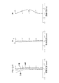
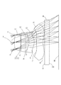
以下に、本発明に係る実施形態について図面を参照しながら詳細に説明する。図1、図3、図5、図7、図9、図11はそれぞれ、本実施形態の実施例1〜6に係る撮像レンズの概略構成図を示している。図1に示されるように、実施例1の撮像レンズは物体側から像側に向かって順に、開口絞りST、光軸Xの近傍で物体側に凸面を向けた正の屈折力を有するメニスカス形状の第1レンズL1、光軸Xの近傍で像側に凸面を向けた正の屈折力を有するメニスカス形状の第2レンズL2、光軸Xの近傍で像側に凸面を向けた正の屈折力を有するメニスカス形状の第3レンズL3、光軸Xの近傍で像側に凹面を向けた負の屈折力を有するメニスカス形状の第4レンズL4とで構成されている。すべてのレンズ面は非球面で形成されており、回折光学面DOEは第1レンズL1の像側の面r2に形成されている。なお、回折光学面DEOは第1レンズL1の像側の面r2から第2レンズL2の像側の面r4のうち、少なくとも一つの面に形成すればよい。第1レンズL1は高屈折率のポリカーボネート系の材料を、第2レンズL2、第3レンズL3、第4レンズL4には低分散のオレフィン系の材料を用いている。また、第4レンズL4と像面IMとの間にはフィルタIRが配置されている。なお、このフィルタIRは省略することが可能である。また、光軸上の距離を算出する際はフィルタを取り外したときの値を採用するものとする。 Hereinafter, embodiments according to the present invention will be described in detail with reference to the drawings. 1, 3, 5, 7, 9, and 11 are schematic configuration diagrams of imaging lenses according to Examples 1 to 6 of the present embodiment, respectively. As shown in FIG. 1, the imaging lens of Example 1 has a meniscus shape having a positive refractive power with a convex surface facing the object side in the vicinity of the aperture stop ST and the optical axis X in order from the object side to the image side. A first meniscus second lens L2 having a positive refractive power with its convex surface facing the image side in the vicinity of the optical axis X, and a positive refractive power with its convex surface facing the image side in the vicinity of the optical axis X. And a meniscus fourth lens L4 having a negative refractive power with a concave surface facing the image side in the vicinity of the optical axis X. All lens surfaces are aspherical, and the diffractive optical surface DOE is formed on the image side surface r2 of the first lens L1. The diffractive optical surface DEO may be formed on at least one of the image side surface r2 of the first lens L1 to the image side surface r4 of the second lens L2. The first lens L1 is made of a polycarbonate material having a high refractive index, and the second lens L2, the third lens L3, and the fourth lens L4 are made of a low dispersion olefin material. Further, a filter IR is disposed between the fourth lens L4 and the image plane IM. This filter IR can be omitted. Also, when calculating the distance on the optical axis, the value when the filter is removed is adopted.
なお、第1レンズL1は物体側に凸面を向けた正の屈折力を有するレンズであれば良く、例えば両面が凸面であってもかまわない。また、第2レンズL2は像側に凸面を向けた正の屈折力を有するレンズであれば良く、例えば両面が凸面であってもかまわない。 The first lens L1 may be a lens having a positive refractive power with a convex surface facing the object side. For example, both surfaces may be convex. The second lens L2 may be any lens having a positive refractive power with the convex surface facing the image side. For example, both surfaces may be convex.
また、すべてのレンズ面は非球面で形成されており、これらのレンズ面に採用する非球面形状は光軸方向の軸をZ、光軸に直交する方向の高さをH、円錐係数をk、非球面係数をA4、A6、A8、A10、A12、A14、A16としたとき数1により表わされる。また、回折光学面の光路差関数は数2で表わされる。 All lens surfaces are aspherical, and the aspherical shape adopted for these lens surfaces is Z for the optical axis direction, H for the direction perpendicular to the optical axis, and k for the conic coefficient. When the aspheric coefficient is A4, A6, A8, A10, A12, A14, and A16, it is expressed by Equation 1. Further, the optical path difference function of the diffractive optical surface is expressed by Equation 2.

P :光路差(単位:波長)
B2i :光路差関数係数(i=1〜7)
P: optical path difference (unit: wavelength)
B 2i : Optical path difference function coefficient (i = 1 to 7)
本実施形態の撮像レンズは以下の条件式(1)〜(9)を満足する。
(1)1.58<Ndi
(2)0.7<TTL/(2IH)<0.9
(3)0.7<f1/f<1.1
(4)0.40<r1/f<1.0
(5)0.6<f123/f<0.9
(6)0.6<Σd/TTL<0.8
(7)0.02<T12/Σd<0.20
(8)0.6<Tie/Ti<1.3
(9)1≦Dn≦20
ただし、
Ndi:i番目の正レンズのd線における屈折率
TTL:フィルタを取り外した際の、第1レンズの物体側の面から撮像面までの光軸上の距離
IH:最大像高
f1:第1レンズの焦点距離
f:全系の焦点距離
r1:第1レンズの物体側の面の曲率半径
f123:第1レンズ、第2レンズ、第3レンズの合成焦点距離
Σd:第1レンズの物体側の面から第4レンズの像側の面までの光軸上の距離
T12:第1レンズの像側の面と第2レンズの物体側の面との光軸上の距離
Ti:i番目のレンズの中心厚
Tie:i番目のレンズのエッジ厚
Dn:回折格子輪帯数(整数)
The imaging lens of this embodiment satisfies the following conditional expressions (1) to (9).
(1) 1.58 <Ndi
(2) 0.7 <TTL / (2IH) <0.9
(3) 0.7 <f1 / f <1.1
(4) 0.40 <r1 / f <1.0
(5) 0.6 <f123 / f <0.9
(6) 0.6 <Σd / TTL <0.8
(7) 0.02 <T12 / Σd <0.20
(8) 0.6 <Tie / Ti <1.3
(9) 1 ≦ Dn ≦ 20
However,
Ndi: refractive index TTL at the d-line of the i-th positive lens: distance on the optical axis from the object side surface of the first lens to the imaging surface when the filter is removed IH: maximum image height f1: first lens Focal length f: total system focal length r1: radius of curvature of object side surface of first lens f123: combined focal length of first lens, second lens, and third lens Σd: object side surface of first lens The distance T12 on the optical axis from the image side surface of the fourth lens to the image side surface of the fourth lens: the distance Ti on the optical axis between the image side surface of the first lens and the object side surface of the second lens: the center of the i-th lens Thickness Tie: Edge thickness of the i-th lens Dn: Number of diffraction grating ring zones (integer)
次に本実施の形態に係る撮像レンズの実施例を示す。各実施例において、fは撮像レンズ全系の焦点距離を、FNoはFナンバーを、ωは半画角を、IHは最大像高をそれぞれ示す。また、iは物体側から数えた面番号、rは曲率半径、dは光軸上のレンズ面間の距離(面間隔)、Ndはd線(基準波長)に対する屈折率、νdはd線に対するアッベ数をそれぞれ示す。なお、非球面に関しては、面番号iの後に*(アスタリスク)の符号を付加して示し、回折光学面が形成された面をDOEで示す。 Next, examples of the imaging lens according to the present embodiment will be described. In each embodiment, f represents the focal length of the entire imaging lens system, FNo represents the F number, ω represents the half field angle, and IH represents the maximum image height. Further, i is a surface number counted from the object side, r is a radius of curvature, d is a distance (surface interval) between lens surfaces on the optical axis, Nd is a refractive index with respect to d-line (reference wavelength), and νd is with respect to d-line. The Abbe numbers are shown. As for the aspherical surface, the surface number i is indicated by adding an asterisk (*) symbol, and the surface on which the diffractive optical surface is formed is indicated by DOE.
基本的レンズデータを以下の表1に示す。
実施例1の撮像レンズは、表7に示すように条件式(1)〜(9)の全てを満たしている。 The imaging lens of Example 1 satisfies all conditional expressions (1) to (9) as shown in Table 7.
図2は実施例1の撮像レンズについて、球面収差(mm)、非点収差(mm)、歪曲収差(%)を示したものである。球面収差図には、F線(486nm)、d線(588nm)、C線(656nm)の各波長に対する収差量を示している。また、非点収差図にはサジタル像面S、タンジェンシャル像面Tにおける収差量をそれぞれ示している。図2に示すように、各収差は良好に補正されていることが分かる。 FIG. 2 shows spherical aberration (mm), astigmatism (mm), and distortion (%) for the imaging lens of Example 1. The spherical aberration diagram shows the amount of aberration with respect to each wavelength of the F-line (486 nm), d-line (588 nm), and C-line (656 nm). The astigmatism diagram shows the amount of aberration on the sagittal image plane S and the tangential image plane T, respectively. As shown in FIG. 2, it can be seen that each aberration is well corrected.
また、光学全長TTLは2.74mmと短く、4枚構成でありながら薄型化が実現されている。さらに、F値は2.4で明るく、半画角は約38.8°で比較的広い画角が実現されている。 Further, the optical total length TTL is as short as 2.74 mm, and the thinning is realized even though the four-lens configuration is used. Further, the F value is 2.4 and it is bright, and the half angle of view is about 38.8 °, and a relatively wide angle of view is realized.
基本的レンズデータを以下の表2に示す。
実施例2の撮像レンズは、表7に示すように条件式(1)〜(9)の全てを満たしている。 The imaging lens of Example 2 satisfies all conditional expressions (1) to (9) as shown in Table 7.
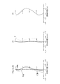
図4は実施例2の撮像レンズについて、球面収差(mm)、非点収差(mm)、歪曲収差(%)を示したものである。球面収差図には、F線(486nm)、d線(588nm)、C線(656nm)の各波長に対する収差量を示している。また、非点収差図にはサジタル像面S、タンジェンシャル像面Tにおける収差量をそれぞれ示している。図4に示すように、各収差は良好に補正されていることが分かる。 FIG. 4 shows spherical aberration (mm), astigmatism (mm), and distortion (%) for the imaging lens of Example 2. The spherical aberration diagram shows the amount of aberration with respect to each wavelength of the F-line (486 nm), d-line (588 nm), and C-line (656 nm). The astigmatism diagram shows the amount of aberration on the sagittal image plane S and the tangential image plane T, respectively. As shown in FIG. 4, it can be seen that each aberration is well corrected.
また、光学全長TTLは2.74mmと短く、4枚構成でありながら薄型化が実現されている。さらに、F値は2.38で明るく、半画角は約38.9°で比較的広い画角が実現されている。 Further, the optical total length TTL is as short as 2.74 mm, and the thinning is realized even though the four-lens configuration is used. Further, the F value is 2.38, which is bright and the half angle of view is about 38.9 °, and a relatively wide angle of view is realized.
基本的レンズデータを以下の表3に示す。
図6は実施例3の撮像レンズについて、球面収差(mm)、非点収差(mm)、歪曲収差(%)を示したものである。球面収差図には、F線(486nm)、d線(588nm)、C線(656nm)の各波長に対する収差量を示している。また、非点収差図にはサジタル像面S、タンジェンシャル像面Tにおける収差量をそれぞれ示している。図6に示すように、各収差は良好に補正されていることが分かる。 FIG. 6 shows spherical aberration (mm), astigmatism (mm), and distortion (%) for the imaging lens of Example 3. The spherical aberration diagram shows the amount of aberration with respect to each wavelength of the F-line (486 nm), d-line (588 nm), and C-line (656 nm). The astigmatism diagram shows the amount of aberration on the sagittal image plane S and the tangential image plane T, respectively. As shown in FIG. 6, it can be seen that each aberration is corrected satisfactorily.
また、光学全長TTLは2.75mmと短く、4枚構成でありながら薄型化が実現されている。さらに、F値は2.41で明るく、半画角は約38.6°で比較的広い画角が実現されている。 Further, the optical total length TTL is as short as 2.75 mm, and the thickness is reduced despite the configuration of four sheets. Further, the F value is 2.41, bright, and the half angle of view is about 38.6 °, which realizes a relatively wide angle of view.
基本的レンズデータを以下の表4に示す。
実施例4の撮像レンズは、表7に示すように条件式(1)〜(9)の全てを満たしている。 The imaging lens of Example 4 satisfies all conditional expressions (1) to (9) as shown in Table 7.
図8は実施例4の撮像レンズについて、球面収差(mm)、非点収差(mm)、歪曲収差(%)を示したものである。球面収差図には、F線(486nm)、d線(588nm)、C線(656nm)の各波長に対する収差量を示している。また、非点収差図にはサジタル像面S、タンジェンシャル像面Tにおける収差量をそれぞれ示している。図8に示すように、各収差は良好に補正されていることが分かる。 FIG. 8 shows spherical aberration (mm), astigmatism (mm), and distortion (%) for the imaging lens of Example 4. The spherical aberration diagram shows the amount of aberration with respect to each wavelength of the F-line (486 nm), d-line (588 nm), and C-line (656 nm). The astigmatism diagram shows the amount of aberration on the sagittal image plane S and the tangential image plane T, respectively. As shown in FIG. 8, it can be seen that each aberration is corrected satisfactorily.
また、光学全長TTLは2.74mmと短く、4枚構成でありながら薄型化が実現されている。さらに、F値は2.31で明るく、半画角は約38.4°で比較的広い画角が実現されている。 Further, the optical total length TTL is as short as 2.74 mm, and the thinning is realized even though the four-lens configuration is used. Further, the F value is 2.31, bright, and the half angle of view is about 38.4 °, so that a relatively wide angle of view is realized.
基本的レンズデータを以下の表5に示す。
実施例5の撮像レンズは、表7に示すように条件式(1)〜(9)の全てを満たしている。 The imaging lens of Example 5 satisfies all conditional expressions (1) to (9) as shown in Table 7.
図10は実施例5の撮像レンズについて、球面収差(mm)、非点収差(mm)、歪曲収差(%)を示したものである。球面収差図には、F線(486nm)、d線(588nm)、C線(656nm)の各波長に対する収差量を示している。また、非点収差図にはサジタル像面S、タンジェンシャル像面Tにおける収差量をそれぞれ示している。図10に示すように、各収差は良好に補正されていることが分かる。 FIG. 10 shows spherical aberration (mm), astigmatism (mm), and distortion (%) for the imaging lens of Example 5. The spherical aberration diagram shows the amount of aberration with respect to each wavelength of the F-line (486 nm), d-line (588 nm), and C-line (656 nm). The astigmatism diagram shows the amount of aberration on the sagittal image plane S and the tangential image plane T, respectively. As shown in FIG. 10, it can be seen that each aberration is corrected satisfactorily.
また、光学全長TTLは2.75mmと短く、4枚構成でありながら薄型化が実現されている。さらに、F値は2.40で明るく、半画角は約38.6°で比較的広い画角が実現されている。 Further, the optical total length TTL is as short as 2.75 mm, and the thickness is reduced despite the configuration of four sheets. Further, the F value is 2.40, which is bright and the half angle of view is about 38.6 °, and a relatively wide angle of view is realized.
基本的レンズデータを以下の表6に示す。
実施例6の撮像レンズは、表7に示すように条件式(1)〜(9)の全てを満たしている。 The imaging lens of Example 6 satisfies all of the conditional expressions (1) to (9) as shown in Table 7.
図12は実施例6の撮像レンズについて、球面収差(mm)、非点収差(mm)、歪曲収差(%)を示したものである。球面収差図には、F線(486nm)、d線(588nm)、C線(656nm)の各波長に対する収差量を示している。また、非点収差図にはサジタル像面S、タンジェンシャル像面Tにおける収差量をそれぞれ示している。図12に示すように、各収差は良好に補正されていることが分かる。 FIG. 12 shows spherical aberration (mm), astigmatism (mm), and distortion (%) for the imaging lens of Example 6. The spherical aberration diagram shows the amount of aberration with respect to each wavelength of the F-line (486 nm), d-line (588 nm), and C-line (656 nm). The astigmatism diagram shows the amount of aberration on the sagittal image plane S and the tangential image plane T, respectively. As shown in FIG. 12, it can be seen that each aberration is corrected satisfactorily.
また、光学全長TTLは2.74mmと短く、4枚構成でありながら薄型化が実現されている。さらに、F値は2.40で明るく、半画角は約39.6°で比較的広い画角が実現されている。 Further, the optical total length TTL is as short as 2.74 mm, and the thinning is realized even though the four-lens configuration is used. Further, the F value is 2.40, which is bright and the half angle of view is about 39.6 °, and a relatively wide angle of view is realized.
本発明の実施形態に係る撮像レンズによれば、4枚構成でありながら、回折光学面DOEの色収差補正機能を適切に応用することで負のレンズを使用することなく、色収差の補正と非常に短い光学全長TTLとの両立が図られていることがわかる。また、全てのレンズ面に適切な非球面形状を形成することで、諸収差が良好に補正されており、さらにF値は2.40程度で明るく、近年の高密度化された撮像素子に適応が可能である。また、半画角ωが38°以上であり広画角化を達成しているため、広範囲な被写体の像の撮影が可能である。 According to the imaging lens according to the embodiment of the present invention, the chromatic aberration can be greatly corrected without using a negative lens by appropriately applying the chromatic aberration correction function of the diffractive optical surface DOE, although it has a four-lens configuration. It can be seen that compatibility with the short optical total length TTL is achieved. Also, by forming appropriate aspheric shapes on all lens surfaces, various aberrations are corrected well, and the F value is about 2.40, which is bright and adaptable to recent high-density image sensors. Is possible. Further, since the half angle of view ω is 38 ° or more and a wide angle of view is achieved, it is possible to shoot images of a wide range of subjects.
表7に実施例1〜6の条件式(1)〜(9)の値を示す。
上述したように、各実施の形態に係る4枚レンズ構成の撮像レンズを携帯電話機やスマートフォンなどの携帯端末、及びPDA(Personal Digital Assistance)、さらには、ゲーム機等に搭載される撮像装置に内蔵される光学系に適用した場合、高性能なカメラ機能の維持と撮像装置の薄型化を可能にすることができる。 As described above, the imaging lens having the four-lens configuration according to each embodiment is incorporated in a portable terminal such as a mobile phone or a smartphone, a PDA (Personal Digital Assistance), or an imaging device mounted on a game machine or the like. When applied to an optical system, it is possible to maintain a high-performance camera function and reduce the thickness of the imaging device.
ST 開口絞り
L1 第1レンズ
L2 第2レンズ
L3 第3レンズ
L4 第4レンズ
IR フィルタ
IM 撮像面
ST Aperture stop L1 First lens L2 Second lens L3 Third lens L4 Fourth lens IR filter IM Imaging surface
Claims (8)
(1)1.58<Ndi
(3)0.7<f1/f≦0.947
ただし、
Ndi:i番目の正レンズのd線における屈折率
f1:第1レンズの焦点距離
f:全系の焦点距離 An imaging lens for a solid-state imaging device, in order from an object side to an image side, an aperture stop, a first lens having a positive refractive power with a convex surface facing the object side in the vicinity of the optical axis, and the vicinity of the optical axis A second lens having a positive refractive power with the convex surface facing the image side, a third lens having a positive refractive power with the convex surface facing the image side near the optical axis, and a concave surface on the image side near the optical axis. And a fourth lens having a negative refractive power directed to the lens, all the lens surfaces are formed of aspherical surfaces, all the lenses are made of a plastic material, and the second lens extends from the image-side surface of the first lens. At least one of the surfaces on the image side of the lens is formed by a diffractive optical surface, and at least one of the three lenses having the positive refractive power satisfies the following conditional expression (1) : An imaging lens that satisfies the following conditional expression (3):
(1) 1.58 <Ndi
(3) 0.7 <f1 / f ≦ 0.947
However,
Ndi: refractive index of the i-th positive lens at the d-line
f1: Focal length of the first lens
f: Focal length of the entire system
(2)0.7<TTL/(2IH)<0.9
ただし、
TTL:フィルタを取り外した際の、第1レンズの物体側から撮像面までの光軸上の距離
IH:最大像高 The imaging lens according to claim 1, wherein the following conditional expression (2) is satisfied.
(2) 0.7 <TTL / (2IH) <0.9
However,
TTL: Distance on the optical axis from the object side of the first lens to the imaging surface when the filter is removed IH: Maximum image height
(4)0.40<r1/f<1.0
ただし、
r1:第1レンズの物体側の面の曲率半径
f:全系の焦点距離 The imaging lens according to claim 1, characterized by satisfying the following conditional expression (4).
(4) 0.40 <r1 / f <1.0
However,
r1: radius of curvature of the object side surface of the first lens f: focal length of the entire system
(5)0.6<f123/f<0.9
ただし、
f123:第1レンズ、第2レンズ、第3レンズの合成焦点距離
f:全系の焦点距離 The imaging lens according to claim 1, wherein the following conditional expression (5) is satisfied.
(5) 0.6 <f123 / f <0.9
However,
f123: the combined focal length of the first lens, the second lens, and the third lens f: the focal length of the entire system
(6)0.6<Σd/TTL<0.8
ただし、
Σd:第1レンズの物体側の面から第4レンズの像側の面までの光軸上の距離
TTL:フィルタを取り外した際の、第1レンズの物体側から撮像面までの光軸上の距離 The imaging lens according to claim 1, wherein the following conditional expression (6) is satisfied.
(6) 0.6 <Σd / TTL <0.8
However,
Σd: Distance on the optical axis from the object side surface of the first lens to the image side surface of the fourth lens TTL: On the optical axis from the object side of the first lens to the imaging surface when the filter is removed distance
(7)0.02<T12/Σd<0.20
ただし、T12:第1レンズの像側の面と第2レンズの物体側の面との光軸上の距離
Σd:第1レンズの物体側の面から第4レンズの像側の面までの光軸上の距離 The imaging lens according to claim 1, wherein the following conditional expression (7) is satisfied.
(7) 0.02 <T12 / Σd <0.20
T12: Distance on the optical axis between the image side surface of the first lens and the object side surface of the second lens Σd: light from the object side surface of the first lens to the image side surface of the fourth lens Axis distance
(9)1≦Dn≦20
ただし、
Dn:回折格子輪帯数(整数) The imaging lens according to claim 1, wherein the following conditional expression (9) is satisfied.
(9) 1 ≦ Dn ≦ 20
However,
Dn: Number of diffraction grating ring zones (integer)
Priority Applications (3)
| Application Number | Priority Date | Filing Date | Title |
|---|---|---|---|
| JP2012123474A JP5973240B2 (en) | 2012-05-30 | 2012-05-30 | Imaging lens |
| US13/898,120 US9341857B2 (en) | 2012-05-30 | 2013-05-20 | Imaging lens comprising a diffractive optical surface |
| CN2013202967462U CN203311088U (en) | 2012-05-30 | 2013-05-28 | Camera lens |
Applications Claiming Priority (1)
| Application Number | Priority Date | Filing Date | Title |
|---|---|---|---|
| JP2012123474A JP5973240B2 (en) | 2012-05-30 | 2012-05-30 | Imaging lens |
Publications (3)
| Publication Number | Publication Date |
|---|---|
| JP2013250330A JP2013250330A (en) | 2013-12-12 |
| JP2013250330A5 JP2013250330A5 (en) | 2015-07-16 |
| JP5973240B2 true JP5973240B2 (en) | 2016-08-23 |
Family
ID=49617287
Family Applications (1)
| Application Number | Title | Priority Date | Filing Date |
|---|---|---|---|
| JP2012123474A Active JP5973240B2 (en) | 2012-05-30 | 2012-05-30 | Imaging lens |
Country Status (3)
| Country | Link |
|---|---|
| US (1) | US9341857B2 (en) |
| JP (1) | JP5973240B2 (en) |
| CN (1) | CN203311088U (en) |
Families Citing this family (23)
| Publication number | Priority date | Publication date | Assignee | Title |
|---|---|---|---|---|
| CN103135207B (en) * | 2012-11-15 | 2015-07-15 | 玉晶光电(厦门)有限公司 | Portable electronic device and optical imaging lens thereof |
| TWI461730B (en) | 2013-07-05 | 2014-11-21 | Largan Precision Co Ltd | Image capturing lens system |
| KR101511442B1 (en) * | 2013-10-28 | 2015-04-13 | 서울과학기술대학교 산학협력단 | LED-ID/RF communication smart device using camera and the method of LBS using the same |
| CN105319671A (en) * | 2014-06-25 | 2016-02-10 | Kolen株式会社 | Camera lens optical system |
| US9772469B2 (en) | 2014-09-17 | 2017-09-26 | Ricoh Company, Ltd. | Image forming lens and image capturing device |
| CN105487205B (en) * | 2014-09-18 | 2017-12-15 | 先进光电科技股份有限公司 | Four-piece type imaging lens group |
| CN104730686B (en) * | 2014-12-19 | 2017-02-22 | 玉晶光电(厦门)有限公司 | Optical imaging lens and electronic device using the same |
| CN105093495B (en) * | 2015-03-17 | 2017-11-10 | 玉晶光电(厦门)有限公司 | The electronic installation of optical imaging lens and the application optical imaging lens |
| CN106094169B (en) * | 2016-08-05 | 2019-03-12 | 嘉兴中润光学科技有限公司 | A kind of optical lens |
| US10288851B2 (en) * | 2016-10-27 | 2019-05-14 | Newmax Technology Co., Ltd. | Four-piece infrared single wavelength lens system |
| CN107092077B (en) * | 2017-06-23 | 2022-09-16 | 浙江舜宇光学有限公司 | Optical imaging system |
| CN107144943B (en) * | 2017-07-18 | 2022-09-09 | 浙江舜宇光学有限公司 | Camera lens |
| CN109387919B (en) * | 2017-08-08 | 2021-10-08 | 玉晶光电(厦门)有限公司 | Optical imaging lens |
| CN107894655B (en) * | 2017-11-07 | 2023-07-14 | 东莞市美光达光学科技有限公司 | Mobile phone lens module adopting annular aperture diffraction optics |
| TWI713838B (en) * | 2018-05-01 | 2020-12-21 | 先進光電科技股份有限公司 | Optical image capturing system |
| TWI713839B (en) * | 2018-05-01 | 2020-12-21 | 先進光電科技股份有限公司 | Optical image capturing system |
| CN109814235B (en) * | 2018-12-28 | 2022-02-08 | 玉晶光电(厦门)有限公司 | Optical imaging lens |
| CN110908076B (en) * | 2019-12-10 | 2021-09-24 | 诚瑞光学(常州)股份有限公司 | Image pickup optical lens |
| WO2021127823A1 (en) * | 2019-12-23 | 2021-07-01 | 诚瑞光学(常州)股份有限公司 | Camera optical lens |
| CN111142221B (en) * | 2019-12-23 | 2021-02-19 | 诚瑞光学(常州)股份有限公司 | Image pickup optical lens |
| CN111025544B (en) * | 2019-12-23 | 2021-10-22 | 诚瑞光学(常州)股份有限公司 | Image pickup optical lens |
| CN113671665B (en) * | 2020-05-15 | 2022-10-21 | 新巨科技股份有限公司 | Four-piece infrared single-wavelength lens group |
| CN111552138A (en) * | 2020-05-29 | 2020-08-18 | Oppo广东移动通信有限公司 | Under-screen camera, imaging method and terminal |
Family Cites Families (22)
| Publication number | Priority date | Publication date | Assignee | Title |
|---|---|---|---|---|
| US5044706A (en) * | 1990-02-06 | 1991-09-03 | Hughes Aircraft Company | Optical element employing aspherical and binary grating optical surfaces |
| US5581405A (en) * | 1993-12-29 | 1996-12-03 | Eastman Kodak Company | Hybrid refractive/diffractive achromatic camera lens and camera using such |
| JP4932105B2 (en) * | 2001-09-26 | 2012-05-16 | 富士フイルム株式会社 | Single focus lens |
| US6950246B2 (en) * | 2003-04-23 | 2005-09-27 | Olympus Corporation | Imaging optical system and apparatus using the same |
| JP4658511B2 (en) * | 2003-04-23 | 2011-03-23 | オリンパス株式会社 | Imaging optical system, imaging apparatus and electronic apparatus equipped with the same |
| CN1928609A (en) * | 2005-09-09 | 2007-03-14 | 鸿富锦精密工业(深圳)有限公司 | Combined lens system |
| CN1940627A (en) * | 2005-09-28 | 2007-04-04 | 鸿富锦精密工业(深圳)有限公司 | Composite lens system |
| WO2009101721A1 (en) * | 2008-02-13 | 2009-08-20 | Nalux Co., Ltd. | Image forming optical system |
| JP5097059B2 (en) * | 2008-09-03 | 2012-12-12 | パナソニック株式会社 | Imaging lens and imaging apparatus using the same |
| US7826149B2 (en) | 2008-12-27 | 2010-11-02 | Largan Precision Co., Ltd. | Optical lens system for taking image |
| JPWO2011004443A1 (en) * | 2009-07-08 | 2012-12-13 | ナルックス株式会社 | Imaging optics |
| JP2011112719A (en) * | 2009-11-24 | 2011-06-09 | Panasonic Corp | Image pickup lens and image pickup device using the same, and portable device equipped with the image pickup device |
| TWI491916B (en) * | 2010-11-09 | 2015-07-11 | Hon Hai Prec Ind Co Ltd | Image lens |
| TWI410693B (en) * | 2010-11-19 | 2013-10-01 | Largan Precision Co Ltd | Image pick-up optical lens assembly |
| JP5699636B2 (en) * | 2011-01-31 | 2015-04-15 | ソニー株式会社 | Optical unit and imaging device |
| TWI436125B (en) * | 2011-03-04 | 2014-05-01 | Largan Precision Co Ltd | Photographing optical lens assembly |
| TWI432822B (en) * | 2011-03-16 | 2014-04-01 | Largan Precision Co | Optical lens assembly for image photographing |
| TWI422899B (en) * | 2011-06-22 | 2014-01-11 | Largan Precision Co Ltd | Optical image lens assembly |
| US8422151B2 (en) * | 2011-09-01 | 2013-04-16 | Newmax Technology Co., Ltd. | Wide-angle imaging lens module |
| JP5818702B2 (en) * | 2012-01-23 | 2015-11-18 | カンタツ株式会社 | Imaging lens |
| JP5992868B2 (en) * | 2012-07-31 | 2016-09-14 | カンタツ株式会社 | Imaging device |
| TWI477805B (en) * | 2013-08-05 | 2015-03-21 | Largan Precision Co Ltd | Image capturing lens assembly and image capturing device |
-
2012
- 2012-05-30 JP JP2012123474A patent/JP5973240B2/en active Active
-
2013
- 2013-05-20 US US13/898,120 patent/US9341857B2/en active Active
- 2013-05-28 CN CN2013202967462U patent/CN203311088U/en not_active Expired - Lifetime
Also Published As
| Publication number | Publication date |
|---|---|
| CN203311088U (en) | 2013-11-27 |
| US9341857B2 (en) | 2016-05-17 |
| JP2013250330A (en) | 2013-12-12 |
| US20130321920A1 (en) | 2013-12-05 |
Similar Documents
| Publication | Publication Date | Title |
|---|---|---|
| JP5973240B2 (en) | Imaging lens | |
| JP6709564B2 (en) | Imaging lens | |
| CN106896473B (en) | Camera lens | |
| JP6573315B2 (en) | Imaging lens | |
| JP6105317B2 (en) | Wide-angle imaging lens | |
| JP6376561B2 (en) | Imaging lens | |
| JP5992868B2 (en) | Imaging device | |
| JP5894839B2 (en) | Imaging lens | |
| JP5894838B2 (en) | Imaging lens | |
| JP6133068B2 (en) | Imaging lens | |
| JP5654384B2 (en) | Imaging lens | |
| JP6021617B2 (en) | Imaging lens | |
| JP5665229B2 (en) | Imaging lens | |
| JP5818702B2 (en) | Imaging lens | |
| CN107272152B (en) | Camera lens | |
| JP6726916B2 (en) | Imaging lens | |
| JP5894847B2 (en) | Imaging lens | |
| JP5985904B2 (en) | Imaging lens | |
| JP6226369B2 (en) | Wide-angle imaging lens | |
| US7532415B2 (en) | Imaging lens | |
| JP6324824B2 (en) | Imaging lens | |
| JP6066179B2 (en) | Imaging lens | |
| JP6710473B2 (en) | Imaging lens | |
| JP6332851B2 (en) | Imaging lens | |
| JP2016071115A (en) | Zoom lens having seven-optical-element configuration |
Legal Events
| Date | Code | Title | Description |
|---|---|---|---|
| A521 | Request for written amendment filed |
Free format text: JAPANESE INTERMEDIATE CODE: A523 Effective date: 20150601 |
|
| A621 | Written request for application examination |
Free format text: JAPANESE INTERMEDIATE CODE: A621 Effective date: 20150601 |
|
| A977 | Report on retrieval |
Free format text: JAPANESE INTERMEDIATE CODE: A971007 Effective date: 20160225 |
|
| A131 | Notification of reasons for refusal |
Free format text: JAPANESE INTERMEDIATE CODE: A131 Effective date: 20160301 |
|
| A521 | Request for written amendment filed |
Free format text: JAPANESE INTERMEDIATE CODE: A523 Effective date: 20160323 |
|
| RD02 | Notification of acceptance of power of attorney |
Free format text: JAPANESE INTERMEDIATE CODE: A7422 Effective date: 20160323 |
|
| TRDD | Decision of grant or rejection written | ||
| A01 | Written decision to grant a patent or to grant a registration (utility model) |
Free format text: JAPANESE INTERMEDIATE CODE: A01 Effective date: 20160705 |
|
| A61 | First payment of annual fees (during grant procedure) |
Free format text: JAPANESE INTERMEDIATE CODE: A61 Effective date: 20160714 |
|
| R150 | Certificate of patent or registration of utility model |
Ref document number: 5973240 Country of ref document: JP Free format text: JAPANESE INTERMEDIATE CODE: R150 |
|
| R250 | Receipt of annual fees |
Free format text: JAPANESE INTERMEDIATE CODE: R250 |
|
| S531 | Written request for registration of change of domicile |
Free format text: JAPANESE INTERMEDIATE CODE: R313531 |
|
| R350 | Written notification of registration of transfer |
Free format text: JAPANESE INTERMEDIATE CODE: R350 |
|
| R250 | Receipt of annual fees |
Free format text: JAPANESE INTERMEDIATE CODE: R250 |
|
| R250 | Receipt of annual fees |
Free format text: JAPANESE INTERMEDIATE CODE: R250 |
|
| S111 | Request for change of ownership or part of ownership |
Free format text: JAPANESE INTERMEDIATE CODE: R313113 |
|
| R371 | Transfer withdrawn |
Free format text: JAPANESE INTERMEDIATE CODE: R371 |
|
| S111 | Request for change of ownership or part of ownership |
Free format text: JAPANESE INTERMEDIATE CODE: R313113 |
|
| R350 | Written notification of registration of transfer |
Free format text: JAPANESE INTERMEDIATE CODE: R350 |
|
| R250 | Receipt of annual fees |
Free format text: JAPANESE INTERMEDIATE CODE: R250 |
|
| R350 | Written notification of registration of transfer |
Free format text: JAPANESE INTERMEDIATE CODE: R350 |
|
| R250 | Receipt of annual fees |
Free format text: JAPANESE INTERMEDIATE CODE: R250 |
|
| R350 | Written notification of registration of transfer |
Free format text: JAPANESE INTERMEDIATE CODE: R350 |