JP5968882B2 - tire - Google Patents
tire Download PDFInfo
- Publication number
- JP5968882B2 JP5968882B2 JP2013517371A JP2013517371A JP5968882B2 JP 5968882 B2 JP5968882 B2 JP 5968882B2 JP 2013517371 A JP2013517371 A JP 2013517371A JP 2013517371 A JP2013517371 A JP 2013517371A JP 5968882 B2 JP5968882 B2 JP 5968882B2
- Authority
- JP
- Japan
- Prior art keywords
- cut
- tread
- edge corner
- tire
- depth
- Prior art date
- Legal status (The legal status is an assumption and is not a legal conclusion. Google has not performed a legal analysis and makes no representation as to the accuracy of the status listed.)
- Expired - Fee Related
Links
Images


Classifications
-
- B—PERFORMING OPERATIONS; TRANSPORTING
- B60—VEHICLES IN GENERAL
- B60C—VEHICLE TYRES; TYRE INFLATION; TYRE CHANGING; CONNECTING VALVES TO INFLATABLE ELASTIC BODIES IN GENERAL; DEVICES OR ARRANGEMENTS RELATED TO TYRES
- B60C11/00—Tyre tread bands; Tread patterns; Anti-skid inserts
- B60C11/03—Tread patterns
- B60C11/12—Tread patterns characterised by the use of narrow slits or incisions, e.g. sipes
-
- B—PERFORMING OPERATIONS; TRANSPORTING
- B60—VEHICLES IN GENERAL
- B60C—VEHICLE TYRES; TYRE INFLATION; TYRE CHANGING; CONNECTING VALVES TO INFLATABLE ELASTIC BODIES IN GENERAL; DEVICES OR ARRANGEMENTS RELATED TO TYRES
- B60C11/00—Tyre tread bands; Tread patterns; Anti-skid inserts
- B60C11/03—Tread patterns
- B60C11/0306—Patterns comprising block rows or discontinuous ribs
-
- B—PERFORMING OPERATIONS; TRANSPORTING
- B60—VEHICLES IN GENERAL
- B60C—VEHICLE TYRES; TYRE INFLATION; TYRE CHANGING; CONNECTING VALVES TO INFLATABLE ELASTIC BODIES IN GENERAL; DEVICES OR ARRANGEMENTS RELATED TO TYRES
- B60C11/00—Tyre tread bands; Tread patterns; Anti-skid inserts
- B60C11/03—Tread patterns
- B60C11/032—Patterns comprising isolated recesses
- B60C11/0323—Patterns comprising isolated recesses tread comprising channels under the tread surface, e.g. for draining water
-
- B—PERFORMING OPERATIONS; TRANSPORTING
- B60—VEHICLES IN GENERAL
- B60C—VEHICLE TYRES; TYRE INFLATION; TYRE CHANGING; CONNECTING VALVES TO INFLATABLE ELASTIC BODIES IN GENERAL; DEVICES OR ARRANGEMENTS RELATED TO TYRES
- B60C11/00—Tyre tread bands; Tread patterns; Anti-skid inserts
- B60C11/03—Tread patterns
- B60C11/04—Tread patterns in which the raised area of the pattern consists only of continuous circumferential ribs, e.g. zig-zag
-
- B—PERFORMING OPERATIONS; TRANSPORTING
- B60—VEHICLES IN GENERAL
- B60C—VEHICLE TYRES; TYRE INFLATION; TYRE CHANGING; CONNECTING VALVES TO INFLATABLE ELASTIC BODIES IN GENERAL; DEVICES OR ARRANGEMENTS RELATED TO TYRES
- B60C11/00—Tyre tread bands; Tread patterns; Anti-skid inserts
- B60C11/03—Tread patterns
- B60C11/11—Tread patterns in which the raised area of the pattern consists only of isolated elements, e.g. blocks
-
- B—PERFORMING OPERATIONS; TRANSPORTING
- B60—VEHICLES IN GENERAL
- B60C—VEHICLE TYRES; TYRE INFLATION; TYRE CHANGING; CONNECTING VALVES TO INFLATABLE ELASTIC BODIES IN GENERAL; DEVICES OR ARRANGEMENTS RELATED TO TYRES
- B60C11/00—Tyre tread bands; Tread patterns; Anti-skid inserts
- B60C11/03—Tread patterns
- B60C11/12—Tread patterns characterised by the use of narrow slits or incisions, e.g. sipes
- B60C11/1272—Width of the sipe
- B60C11/1281—Width of the sipe different within the same sipe, i.e. enlarged width portion at sipe bottom or along its length
-
- B—PERFORMING OPERATIONS; TRANSPORTING
- B60—VEHICLES IN GENERAL
- B60C—VEHICLE TYRES; TYRE INFLATION; TYRE CHANGING; CONNECTING VALVES TO INFLATABLE ELASTIC BODIES IN GENERAL; DEVICES OR ARRANGEMENTS RELATED TO TYRES
- B60C11/00—Tyre tread bands; Tread patterns; Anti-skid inserts
- B60C11/03—Tread patterns
- B60C11/13—Tread patterns characterised by the groove cross-section, e.g. for buttressing or preventing stone-trapping
- B60C11/1376—Three dimensional block surfaces departing from the enveloping tread contour
- B60C11/1392—Three dimensional block surfaces departing from the enveloping tread contour with chamfered block edges
-
- B—PERFORMING OPERATIONS; TRANSPORTING
- B60—VEHICLES IN GENERAL
- B60C—VEHICLE TYRES; TYRE INFLATION; TYRE CHANGING; CONNECTING VALVES TO INFLATABLE ELASTIC BODIES IN GENERAL; DEVICES OR ARRANGEMENTS RELATED TO TYRES
- B60C11/00—Tyre tread bands; Tread patterns; Anti-skid inserts
- B60C11/03—Tread patterns
- B60C11/12—Tread patterns characterised by the use of narrow slits or incisions, e.g. sipes
- B60C11/1204—Tread patterns characterised by the use of narrow slits or incisions, e.g. sipes with special shape of the sipe
- B60C2011/1209—Tread patterns characterised by the use of narrow slits or incisions, e.g. sipes with special shape of the sipe straight at the tread surface
-
- B—PERFORMING OPERATIONS; TRANSPORTING
- B60—VEHICLES IN GENERAL
- B60C—VEHICLE TYRES; TYRE INFLATION; TYRE CHANGING; CONNECTING VALVES TO INFLATABLE ELASTIC BODIES IN GENERAL; DEVICES OR ARRANGEMENTS RELATED TO TYRES
- B60C11/00—Tyre tread bands; Tread patterns; Anti-skid inserts
- B60C11/03—Tread patterns
- B60C11/12—Tread patterns characterised by the use of narrow slits or incisions, e.g. sipes
- B60C11/1204—Tread patterns characterised by the use of narrow slits or incisions, e.g. sipes with special shape of the sipe
- B60C2011/1231—Tread patterns characterised by the use of narrow slits or incisions, e.g. sipes with special shape of the sipe being shallow, i.e. sipe depth of less than 3 mm
-
- B—PERFORMING OPERATIONS; TRANSPORTING
- B60—VEHICLES IN GENERAL
- B60C—VEHICLE TYRES; TYRE INFLATION; TYRE CHANGING; CONNECTING VALVES TO INFLATABLE ELASTIC BODIES IN GENERAL; DEVICES OR ARRANGEMENTS RELATED TO TYRES
- B60C11/00—Tyre tread bands; Tread patterns; Anti-skid inserts
- B60C11/03—Tread patterns
- B60C11/12—Tread patterns characterised by the use of narrow slits or incisions, e.g. sipes
- B60C11/1259—Depth of the sipe
- B60C2011/1268—Depth of the sipe being different from sipe to sipe
Description
本発明は、重車両用タイヤに関し、特にかかるタイヤのトレッドに関する。 The present invention relates to a heavy vehicle tire, and more particularly to a tread of such a tire.
重車両用タイヤは、半径方向外面が走行中、路面に接触するようになったトレッド表面(踏み面ともいう)を形成するトレッドを有している。このトレッドは、路面との接触時、雨天において路面上に存在する水を分散させることができる容積部を形成する溝を公知の仕方で備えている。これら溝は、摩耗すべきトレッドの厚みに実質的に一致した深さを有し、これら溝は、ブロック又はリブの形態をした隆起要素を画定している。各隆起要素は、トレッドのトレッド表面の一部をなす接触フェース及びエッジコーナー部に沿ってこの接触面と交差する側壁を有する。 The heavy vehicle tire has a tread that forms a tread surface (also referred to as a tread surface) that comes into contact with the road surface while the outer surface in the radial direction travels. This tread is provided with a groove in a known manner that forms a volume that can disperse water present on the road surface in the rain when in contact with the road surface. These grooves have a depth substantially corresponding to the thickness of the tread to be worn, and these grooves define raised elements in the form of blocks or ribs. Each raised element has a contact face that forms part of the tread surface of the tread and a sidewall that intersects the contact surface along the edge corner.
これらトレッドの剛性を過度に減少させないでこれらトレッドのグリップ性能を向上させるため、これら隆起要素が路面に接触すると少なくとも部分的に閉鎖することができるという利点を備えたサイプを隆起要素に設けることが慣例である。各サイプは、溝の深さの少なくとも50%に等しい深さを有し、各サイプは、これを画定する互いに向かい合ったフェース相互間の距離に一致した幅を有し、この幅は、正確に言ってこれら対向したフェースが互いに接触することができるようにするために溝の幅よりも細い。 In order to improve the grip performance of these treads without excessively reducing the rigidity of these treads, the raised elements can be provided with sipes with the advantage that they can be at least partially closed when they contact the road surface. It is customary. Each sipe has a depth equal to at least 50% of the depth of the groove, and each sipe has a width corresponding to the distance between the opposing faces that define it, which is precisely In other words, the width of the groove is narrower so that these opposed faces can contact each other.
本明細書では、溝は、少なくとも2mmに等しい幅を有し、サイプは、2mm未満の幅を有する。 As used herein, the groove has a width equal to at least 2 mm and the sipe has a width of less than 2 mm.
各サイプは、2つのエッジコーナー部に沿って隆起要素の接触フェースと交差する。これらエッジコーナー部は、トレッドが新品であるとき、即ち、トレッドがまだ走行していないとき、特定の利益をもたらす。これは、これらエッジコーナー部が新品状態においてグリップに有効な寄与をなすからである。 Each sipe intersects the raised element contact face along two edge corners. These edge corners provide certain benefits when the tread is new, i.e. when the tread is not yet running. This is because these edge corner portions make an effective contribution to the grip in a new state.
本出願人は、特に過酷な使用条件下において、サイプにより形成された或る特定のエッジコーナー部の付近に位置するトレッドの材料が少量の材料の引き裂きを来す場合があり、それによりこれらエッジコーナー部の性能が低下し、潜在的に局所的に顕著な摩耗(不均一摩耗と呼ばれている)が生じ、これがタイヤの使用中に悪化するということを究明した。 Applicants have found that under particularly severe conditions of use, the tread material located near certain edge corners formed by the sipe may cause a small amount of material tearing, thereby causing these edges to tear. It has been determined that the corner performance is degraded and potentially locally noticeable wear (referred to as non-uniform wear) occurs, which worsens during tire use.
定義 Definition
赤道中間面は、タイヤの回転軸線に垂直であり且つこの回転軸線から半径方向最も遠くに位置するタイヤ上の箇所を通る平面である。 The equator intermediate plane is a plane that passes through a point on the tire that is perpendicular to the rotation axis of the tire and radially farthest from the rotation axis.
ブロックは、トレッドに形成されていて、中空部又は溝により画定され且つ側壁及び路面に接触するようになった接触フェースを有する隆起要素である。 The block is a raised element formed in the tread and having a contact face defined by a hollow or groove and adapted to contact the side wall and the road surface.
切れ目は、サイプ若しくは溝又はサイプと溝の組み合わせのいずれかであると言える。 サイプは、タイヤの使用条件下において、少なくとも部分的に互いに接触することができるよう互いに距離を置いたところに位置する材料の2つの壁相互間の空間に対応している。 A break can be said to be either a sipe or groove or a combination of sipe and groove. Sipes correspond to the space between two walls of material that are located at a distance from each other so that they can at least partially contact each other under the conditions of use of the tire.
溝は、互いに接触することはない材料の2つの壁相互間の空間に対応している。 The groove corresponds to the space between two walls of material that do not contact each other.
本明細書において半径方向は、互いの回転軸線に垂直な方向を意味している(この方向は、トレッドの厚さ方向に一致している)。 In this specification, the radial direction means a direction perpendicular to the rotation axis of each other (this direction coincides with the thickness direction of the tread).
軸方向は、タイヤの回転軸線に平行な方向を意味している。 The axial direction means a direction parallel to the rotation axis of the tire.
円周方向は、軸方向と半径方向の両方に垂直であり、タイヤの回転軸線を中心とする任意の円の接する方向を意味している。 The circumferential direction is perpendicular to both the axial direction and the radial direction, and means a direction in which an arbitrary circle around the rotation axis of the tire is in contact.
本発明は、重車両用タイヤトレッドに形成されたサイプの付近における材料の引き裂きを回避し、かくしてトレッドの不均一摩耗を回避することを目的としている。 The object of the present invention is to avoid material tearing in the vicinity of a sipe formed on a heavy vehicle tire tread, thus avoiding uneven wear on the tread.
トレッドの全厚は、タイヤの更正(リトレッド)か交換かのいずれかによってこのトレッドを再生しなければならない事態以前において摩耗可能なトレッドの全厚を意味するものと理解されなければならない。 The total thickness of the tread should be understood to mean the total thickness of the tread that can be worn before the tread must be regenerated either by retreading or replacing the tire.
この目的のため、本発明の一要旨は、補強ベルトを載せた半径方向カーカス補強材を有するタイヤであって、補強ベルトには半径方向外側に厚さEのトレッドが載っており、トレッドは、路面に接触するようになっていて且つ多くともトレッドの厚さEに等しい深さPの溝を備えているトレッド表面を有し、溝は、隆起要素を画定し、各隆起要素は、トレッド表面の一部を形成する接触フェース及びエッジコーナー部を形成するよう接触フェースと交差する側方フェースを有し、複数の隆起要素がエッジコーナー部を形成するよう隆起要素の接触フェース上に開口した少なくとも1つの切れ目を有し、切れ目は、多くともトレッドの厚さEに等しい全深さHにわたって隆起要素中に延び、切れ目は、接触フェースと多くとも全深さHに等しい深さH1との間に関し、タイヤの通常の走行条件下において少なくとも部分的に閉鎖可能であるのに適した幅Dを有するサイプの形態をしている形式のタイヤにある。このタイヤは、トレッド表面上のこの切れ目の少なくとも1つのエッジコーナー部の付近に、即ち、サイプの幅Dの多くとも5倍に等しい距離のところに、切れ目の全深さHと比較して小さい深さhを有し、即ち、全深さHの多くとも30%に等しい深さhを有する少なくとも1つの空所が形成され、この少なくとも1つの空所は、少なくとも1つのエッジコーナー部の付近のトレッドの圧縮剛性を減少させることを特徴としている。 For this purpose, one aspect of the present invention is a tire having a radial carcass reinforcing material on which a reinforcing belt is mounted, and the reinforcing belt has a tread having a thickness E on the outer side in the radial direction. Having a tread surface adapted to contact the road surface and having a groove with a depth P equal to at most the thickness E of the tread, the groove defining a raised element, each raised element being a tread surface A contact face that forms part of the side face and a side face that intersects the contact face to form an edge corner, and wherein the plurality of raised elements are open on the contact face of the raised element to form an edge corner Having one cut, the cut extending into the raised element over a total depth H equal to the thickness E of the tread, the cut being equal to the contact face and at most the total depth H The respect between H1, in the form of a tire in the form of a sipe having a width D which is suitable for a least partially closed at normal running conditions of the tire. This tire is small compared to the total depth H of the cut, in the vicinity of at least one edge corner of the cut on the tread surface, ie at a distance equal to at most 5 times the width D of the sipe. At least one cavity is formed having a depth h, ie having a depth h equal to at most 30% of the total depth H, the at least one cavity being in the vicinity of at least one edge corner It is characterized by reducing the compression rigidity of the tread.
このようにして局所的に(即ち、サイプのエッジコーナー部のできるだけ近くのところで)改変を行うことによって切れ目の各エッジコーナー部の付近に形成された空所は、走行中における考えられる攻撃と関連した材料の引き裂きに対するこの切れ目の感受性を低下させる。 The voids formed near each edge corner of the cut by making modifications locally (ie as close as possible to the edge corner of the sipe) in this way are associated with possible attacks during the run. Reducing the susceptibility of this break to tearing of the material.
「切れ目のエッジコーナー部の付近における」という表現は、空所のうちの少なくとも或る特定のものが切れ目の長さの全て又はほぼ全てにわたり且つこの切れ目の各側で延びる領域においてトレッド表面又は隆起要素の接触フェース上に形成されることを意味するものと理解されるべきである。各エッジコーナー部に関して測定した長さL1の領域にわたって少なくとも1つの空所が存在する。この幅は、所望の効果が得られるようにするために比較的小さい(多くともサイプの幅Dの5倍に等しい)ように選択される。この幅の上限の方では、エッジコーナー部の可撓性向上効果は、走行中における耐攻撃性に対して影響を及ぼすほどではない。 The expression “in the vicinity of the edge corner of the cut” means that the tread surface or ridge in the region where at least certain of the cavities extend over all or nearly the entire length of the cut and on each side of the cut. It should be understood to mean formed on the contact face of the element. There is at least one void across the region of length L1 measured for each edge corner. This width is chosen to be relatively small (at most equal to 5 times the sipe width D) in order to obtain the desired effect. At the upper limit of the width, the effect of improving the flexibility of the edge corner portion does not affect the resistance to attack during running.
好ましくは、このエッジコーナー部の近くのトレッドの可撓性向上効果を広げるために複数の空所が切れ目の少なくとも1つのエッジコーナー部の付近に形成される。 Preferably, a plurality of voids are formed in the vicinity of at least one edge corner portion of the cut in order to expand the flexibility improving effect of the tread near the edge corner portion.
一好適例では、空所が形成される領域の全幅は、トレッド表面上の切れ目の幅Dの多くとも30倍に等しい。 In a preferred embodiment, the total width of the area where the void is formed is equal to at most 30 times the width D of the cut on the tread surface.
サイプのエッジコーナー部の各々の付近に位置するこれら小さな表面空所の存在により、隆起要素の可撓性は、エッジコーナー部の動作を妨げないで材料を引き裂く傾向のある応力に良好に抵抗することが望ましいと判明した極めて局所的な仕方で高められる。 Due to the presence of these small surface cavities located near each of the sipe edge corners, the flexibility of the raised elements resists stresses that tend to tear the material without interfering with the movement of the edge corners. It is enhanced in a very local way that has proven desirable.
本発明は、横方向に延び又は横方向に対して交互に円周方向に又はそれどころか斜めの方向に延びる切れ目に利用できる。 The present invention can be used in cuts extending in the lateral direction or alternately in the circumferential direction or even in an oblique direction with respect to the lateral direction.
本発明は又、溝が設けられていない全厚Eのトレッドを備えたタイヤに利用され、このトレッドは、円周方向に又は実質的に円周方向に延び、そしてエッジコーナー部を形成するようトレッド表面上に開口した少なくとも1つの切れ目を有し、各切れ目は、トレッドの厚さEに多くとも等しい全深さHにわたってトレッド中に延び、この切れ目は、トレッド表面と全深さHに多くとも等しい深さH1との間に関し、タイヤの通常の走行条件下において少なくとも部分的に閉鎖可能であるのに適した幅Dを有するサイプの形態をしている。トレッドの圧縮剛性を局所的に減少させることによってエッジコーナー部を保護するため、少なくとも或る特定のエッジコーナー部の付近に、即ち、サイプの幅Dの多くとも5倍に等しい距離のところに且つトレッド表面上に、切れ目の全深さHと比較して小さい深さを有し、即ち、全深さHの多くとも30%に等しい深さを有する少なくとも1つの空所が形成される。 The present invention is also utilized in a tire with a full thickness E tread that is not grooved, the tread extending circumferentially or substantially circumferentially and forming an edge corner. Having at least one cut open on the tread surface, each cut extending into the tread over a total depth H equal to at most the thickness E of the tread, this cut being more at the tread surface and the total depth H In the form of a sipe having a width D suitable for being at least partly closable under normal driving conditions of the tire with respect to an equal depth H1. In order to protect the edge corners by locally reducing the compression stiffness of the tread, at least in the vicinity of certain edge corners, i.e. at a distance equal to at most 5 times the width D of the sipe and On the tread surface, at least one cavity is formed which has a depth which is small compared to the total depth H of the cut, ie has a depth equal to at most 30% of the total depth H.
好ましい一実施形態によれば、各空所の深さhは、切れ目の全高Hの多くとも15%に等しい。 According to one preferred embodiment, the depth h of each cavity is equal to at most 15% of the overall height H of the cut.
好ましい一実施形態によれば、これら空所は、好ましくは多くとも2mmに等しく又は更により好ましくは多くとも1mmに等しい深さの細い溝の形態をしている。 According to a preferred embodiment, these cavities are in the form of narrow grooves preferably having a depth equal to at most 2 mm or even more preferably equal to at most 1 mm.
好ましい実施形態によれば、細い溝は、エッジコーナー部の同一側で互いに平行に延びる。別の変形形態では、これら細い溝は、切れ目のエッジコーナー部に平行に延びても良い。 According to a preferred embodiment, the narrow grooves extend parallel to each other on the same side of the edge corner. In another variant, these narrow grooves may extend parallel to the edge corners of the cut.
好ましい一実施形態によれば、これら空所は、接触フェース上に円形若しくは実質的に円形であり又は長方形若しくは三角形の形をしている場合のある閉じられた輪郭線のエッジコーナー部を形成するために、切れ目の全深さと比較して小さい深さの円筒形の穴の形状をしている。空所は、切頭円錐形の形(この場合、多くとも10°の逃げ角が存在する)及び切れ目の全深さと比較して小さい、即ち、この深さの多くとも30%の深さを有するのが良い。空所の深さは、好ましくは、多くとも2mmに等しく、更により好ましくは、多くとも1mmに等しい。穴の場合、少なくとも1つの列をなす穴がサイプの各エッジコーナー部の付近に形成され、この少なくとも1つの穴列は、エッジコーナー部のうちの1つに平行に延びる。 According to a preferred embodiment, these cavities form a closed contour edge corner that may be circular or substantially circular or may have a rectangular or triangular shape on the contact face. Therefore, it has a cylindrical hole shape with a depth smaller than the entire depth of the cut. The void is small compared to the frustoconical shape (in this case there is a relief angle of at most 10 °) and the total depth of the cut, ie at most 30% of this depth. It is good to have. The depth of the void is preferably at most equal to 2 mm, and even more preferably at most equal to 1 mm. In the case of holes, at least one row of holes is formed near each edge corner of the sipe, and the at least one row of holes extends parallel to one of the edge corners.
別の好ましい実施形態によれば、空所は、互いに平行に延びる複数の溝の形態をしている。この場合、溝は、細長い全体形状の空所、即ち、同一溝の他の寸法と比較して1つの極めて長い寸法(少なくとも10倍)を有する空所を意味している。 According to another preferred embodiment, the cavity is in the form of a plurality of grooves extending parallel to each other. In this case, a groove means an elongated overall shaped cavity, ie a cavity having one very long dimension (at least 10 times) compared to other dimensions of the same groove.
有利には、溝の形態をした各空所は、保護されるべき切れ目のエッジコーナー部に平行に延びる。 Advantageously, each cavity in the form of a groove extends parallel to the edge corner of the cut to be protected.
本発明の別の実施形態によれば、空所は、互いに平行に且つサイプのエッジコーナー部の方向と0°以外の角度をなすように延びる複数の溝の形態をしている。この角度は、好ましくは、少なくとも45°に等しい。 According to another embodiment of the invention, the void is in the form of a plurality of grooves extending parallel to each other and at an angle other than 0 ° with the direction of the edge corner of the sipe. This angle is preferably at least equal to 45 °.
本発明の別の実施形態によれば、切れ目は、トレッドの部分摩耗後に、表面のところに新たな溝を形成するようになった最大幅Kのチャネルを介してトレッド中に延びるサイプの形態をしている。空所が形成されている領域のこの幅は、保護されるべきエッジコーナー部に垂直に測定される。 According to another embodiment of the present invention, the cut is in the form of a sipe that extends into the tread through a channel of maximum width K that is adapted to form a new groove at the surface after partial wear of the tread. doing. This width of the area where the void is formed is measured perpendicular to the edge corner to be protected.
本発明の別の実施形態によれば、本明細書において記載している変形形態のうちの1つ又は他のものを一段と改良するには、切れ目の少なくとも1つのエッジコーナー部の付近の少なくとも1つの空所の存在と切れ目の少なくとも1つのエッジコーナー部に設けられた面取り部の存在を組み合わせるのが良い。面取り部は、切れ目の深さと比較して小さい(即ち、切れ目の深さの多くとも10%に等しい深さにわたって)高さのものであって、トレッド表面と90°未満の平均角度をなす部分を意味している。好ましくは、この平均角度は、45°に近く又はこれに等しい。各面取り部の幾何学的形状は、平坦であっても良く、湾曲していても良い。 According to another embodiment of the invention, to further improve one or the other of the variations described herein, at least one near the at least one edge corner of the cut. It is preferable to combine the presence of one void and the presence of a chamfered portion provided at at least one edge corner portion of the cut. The chamfered portion is small compared to the depth of the cut (ie, over a depth equal to at most 10% of the depth of the cut) and forms an average angle with the tread surface of less than 90 ° Means. Preferably, this average angle is close to or equal to 45 °. The geometric shape of each chamfered portion may be flat or curved.
面取り部の存在により、切れ目のエッジコーナー部とこの切れ目の壁のうちの一方との間に、傾斜した部分が作られる。この傾斜部分上に、切れ目のエッジコーナー部に平行に延びる少なくとも1本の溝の形態をした少なくとも1つの空所を形成することが有利である場合がある。 Due to the presence of the chamfered portion, an inclined portion is formed between the edge corner portion of the cut and one of the walls of the cut. It may be advantageous to form on this inclined part at least one cavity in the form of at least one groove extending parallel to the edge corners of the cut.
有利には、切れ目の少なくとも1つのエッジコーナー部は、面取り部を有し、面取り部は、面取り部の付近のトレッドの圧縮剛性を減少させるようになった少なくとも1つの空所の形態をしてトレッド表面上に延びる。トレッド表面上に形成された空所に類似した空所が、各面取り部上に形成されても良い。 Advantageously, at least one edge corner of the cut has a chamfer, the chamfer being in the form of at least one cavity adapted to reduce the compression stiffness of the tread in the vicinity of the chamfer. Extends on the tread surface. A void similar to the void formed on the tread surface may be formed on each chamfer.
有利には、空所は、切れ目の1つのエッジコーナー部から始まってこのエッジコーナー部と同一側に位置した隆起要素のエッジに向かって進む様々な寸法のものであるのが良い。特に、空所の寸法の変化に従って隆起要素の可撓性の向上を加減することが可能である。 Advantageously, the voids may be of various dimensions starting from one edge corner of the cut and going towards the edge of the raised element located on the same side as this edge corner. In particular, it is possible to increase or decrease the flexibility of the raised elements according to changes in the dimensions of the voids.
例えば、切れ目により形成されたエッジコーナー部の最も近くのところに、エッジコーナー部に対する距離につれて変化する寸法を有する空所を位置決めすることが可能である。かくして、次第に可撓性が向上する効果を得るために、空所の深さ又は幅(溝の場合)又は直径(円筒形穴の場合)の変化をもたらすことが可能である。 For example, a void having a dimension that varies with distance to the edge corner can be positioned closest to the edge corner formed by the cut. Thus, it is possible to bring about changes in the depth or width (in the case of grooves) or diameter (in the case of cylindrical holes) of the voids in order to obtain the effect of gradually increasing flexibility.
かくして、切れ目の各エッジコーナー部に向かって増大する深さを有する空所を形成することによってエッジコーナー部の最も近くのところで達成される可撓性の向上度を大きくすることができる。別の実施形態では、空所が各エッジコーナー部に近づくにつれて空所の密度を増大させるのが良く、空所の密度は、単位面積当たりの空所の容積を意味している。有利な一変形形態では、空所は、切れ目のエッジコーナー部と関連してこれら空所の距離で決まる空所間距離のところに配置される。 Thus, it is possible to increase the degree of flexibility achieved near the edge corners by forming cavities with increasing depths towards each edge corner of the cut. In another embodiment, the density of the cavities may increase as the cavities approach each edge corner, and the density of the cavities means the volume of the cavities per unit area. In one advantageous variant, the cavities are arranged at an inter-vacuum distance determined by the distance between these cavities in relation to the edge corners of the cut.
本発明の改良により、本発明のタイヤのトレッドは、複数の隆起要素を有し、これら隆起要素のうちの少なくとも1つは、隆起要素の接触フェース上に2つのエッジコーナー部を形成する少なくとも1つの切れ目を備えている。これらエッジコーナー部は、切れ目の各エッジコーナー部の付近の隆起要素の可撓性を向上するためにこれらの付近に、即ち、切れ目の幅Dの多くとも5倍に等しい距離のところに少なくとも1つの主空所を備えている。さらに、この隆起要素は、各主空所の各側に形成された複数の追加の空所を有し、これら追加の空所の密度は、多少なりとも隆起要素の中央部分に相当する切れ目の中間部分に関して高い。事実、追加の空所は、これらが隆起要素のエッジの圧縮剛性を変更しないようかかるエッジから十分に遠ざかって位置するように且つ中央部分のこれら剛性を変更するために形成される。 According to an improvement of the invention, the tread of the tire according to the invention has a plurality of raised elements, at least one of these raised elements forming at least one edge corner on the contact face of the raised element. Has two cuts. These edge corners are at least 1 in their vicinity, i.e. at a distance equal to at most 5 times the width D of the cut, in order to improve the flexibility of the raised elements near each edge corner of the cut. Has two main cavities. In addition, the raised element has a plurality of additional cavities formed on each side of each main cavity, the density of these additional cavities being more or less equivalent to the central portion of the raised element. High for the middle part. In fact, additional voids are formed in order to change these stiffnesses of the central portion so that they are located sufficiently far from such edges so that they do not change the compression stiffness of the edges of the raised elements.
本発明の別の特徴及び別の利点は、以下において添付の図面を参照して与えられる説明から明らかになろう。なお、添付の図面は、非限定的な実施例として、本発明の要旨の幾つかの実施形態を示している。 Other features and advantages of the present invention will become apparent from the description given below with reference to the accompanying drawings. The accompanying drawings show some embodiments of the gist of the present invention as non-limiting examples.
図を理解しやすくするために、同一の参照符号が構造的か機能的かのいずれかにおいて同一種類の要素を示す場合、本発明の変形形態を説明するのに同一の参照符号が用いられている場合がある。 To facilitate understanding of the figures, the same reference signs are used to describe variations of the invention when the same reference signs indicate the same type of elements, either structural or functional. There may be.
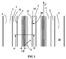
図1は、重車両に用いられるサイズ265/55R17.5のタイヤのための本発明のトレッド1の踏み面又はトレッド表面10の部分図である。このトレッドは、2つの中間リブ3(幅64mm)を画定する3本の円周方向溝2及びトレッドを軸方向に画定するエッジリブ4(幅40mm)を有する。トレッド1は、17.5mmに等しい全厚Eを有し、円周方向溝2は、この全厚Eに多くとも等しい深さPを有する(この場合、溝のこの深さPは、14.5mmに等しい)。
FIG. 1 is a partial view of a tread or tread
トレッド1は、走行中、道路の表面に接触するようになったトレッド表面10を有する。各中間リブ3は、半径方向外側に位置していて、接触フェース31を形成すると共にトレッド表面の一部をなすフェースを有する。各中間リブ3は、円周方向に差し向けられたエッジコーナー部32に沿って接触フェース31と交差する側方フェース30を有する。各リブの軸方向(又は横方向)幅は、これらエッジコーナー部を隔てる距離に一致している。
The tread 1 has a
さらに、2つの中間リブ3は各々、円周方向に延びる切れ目5を備えている。この図1では、円周方向は、矢印Cで示されている。
Further, each of the two
図1のII‐II線矢視断面である図2で理解できるように、トレッドの厚さEに多くとも等しい全深さHのこの切れ目5は、リブ3の接触フェース31上に開口した平均幅0.6mmのサイプの形態をしている。本明細書において、サイプという用語は、壁が走行中、互いに全体的に又は部分的に接触することができる切れ目を意味している。
As can be seen in FIG. 2, which is a cross-sectional view taken along line II-II in FIG. 1, this
この切れ目5は、2つのエッジコーナー部50を形成するよう中間リブ3の接触フェース31と交差しており、これら2つのエッジコーナー部は、この場合、リブを軸方向に境界付けるエッジコーナー部32に平行である。
This
切れ目5によって形成されるエッジコーナー部50の付近に位置する各中間リブ3の力学抵抗を向上させるため、接触フェース31上に且つこれらエッジコーナー部の各々の付近に、複数の空所が形成され、空所は、この場合、0.6mmに等しい平均の浅い深さ及び実質的に0.6mmに等しい幅の表面溝6の形態をしている。幅L0(この場合、幅0.6mmの5倍に等しく、即ち、3mmである)のストリップでは、各エッジコーナー部50から始まって、2つの表面溝6が形成され、これら表面溝は、この場合、互いに且つサイプのエッジコーナー部50に平行である(従って、これら表面溝は、円周方向に延びる)。図を理解しやすくするために、各図は、縮尺通りには画かれてはおらず、特に、表面溝6を備えた領域の幅は、誇張されていることに注目されたい。
In order to improve the mechanical resistance of each
この実施形態は、当然のことながら、それ自体本発明を制限するものではなく、具体的に説明すると、切れ目は、幾つかのリブ全体にわたり又はこれらリブの全てにわたって存在する場合があり、これら切れ目により形成されるエッジコーナー部の付近に互いにほぼ等しい細い表面溝を提供することが望ましい場合がある。 This embodiment is, of course, not limiting the invention per se, and in particular, the cuts may exist over several ribs or over all of these ribs. It may be desirable to provide narrow surface grooves that are approximately equal to each other in the vicinity of the edge corners formed by.
図1及び図2と関連して与えられる実施例は、円周方向に実質的に真っ直ぐである切れ目を示しており、同じ本発明は、これらの全体的な向きがどのようなものであれ波形又はジグザグの切れ目の場合にも利用できる。 The examples given in connection with FIGS. 1 and 2 show cuts that are substantially straight in the circumferential direction, and the same invention is corrugated whatever their overall orientation is. Or it can be used for zigzag cuts.
図3は、本発明のタイヤの変形形態の断面図であり、切れ目が部分摩耗後、トレッド表面上に新たな溝を形成するようになったチャネル52を形成する内側部分を有している。この変形形態では、切れ目5は、新品のままの状態ではトレッド表面上に開口した幅0.6mmのサイプ51で形成され、このサイプ51の延長部として、最大軸方向幅K(この場合、7.2mmに等しい)のチャネル52を形成する広幅部が設けられている。このチャネルは、台形の形をしており、高さが7.2mmである。
FIG. 3 is a cross-sectional view of a variation of the tire of the present invention, where the cut has an inner portion that forms a
サイプにより形成されるエッジコーナー部の付近の各リブの力学抵抗を向上させるため、これらエッジコーナー部の各々の付近に、即ち、少なくとも、サイプの幅の5倍に等しい幅のストリップに、複数の空所が形成されており、これら空所は、この場合、0.6mmに等しい平均深さ及び実質的に0.6mmの幅の溝の形態をしている。これら細い溝は、サイプのエッジコーナー部50に平行である。これら溝のうちの少なくとも1つは、幅L0のストリップに形成され、他の溝も又、幅L0とチャネル52の最大幅Kの1/4に少なくとも等しい幅L1との間に形成されている(この場合、幅L1は、最大幅Kに等しい)。
In order to improve the mechanical resistance of each rib in the vicinity of the edge corner formed by the sipe, a plurality of strips in the vicinity of each of these edge corners, i.e., at least in a width equal to 5 times the width of the sipe. Voids are formed, which in this case are in the form of grooves with an average depth equal to 0.6 mm and a width of substantially 0.6 mm. These narrow grooves are parallel to the
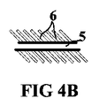
図4A及び図4Bは、切れ目5のエッジコーナー部の付近に細いサイプ6を用いた本発明の2つの変形形態を示している。細いサイプ6は、この場合、これらサイプが短い長さを有し、切れ目のエッジコーナー部の方向とゼロ度以外の角度をなすことを意味している。図4Aは、切れ目のエッジコーナー部の方向に垂直な複数の細いサイプ6を示している。図4Bは、細い切れ目が設けられている切れ目5の側がどちらであっても細いサイプが全て同一の傾きを有する変形形態を示している。これら同一のサイプは、当然のことながら、一方の側に他方の側と比較して異なる傾きを有しても良い。
4A and 4B show two variants of the present invention using a
図5及び図6は、切れ目の付近に複数の穴を用いた本発明の変形形態を示している。穴は、トレッド表面上への開口部が閉じられた輪郭線を有する空所を意味している。 5 and 6 show a modification of the present invention using a plurality of holes near the cut. A hole means a void having a contour with a closed opening on the tread surface.
図5は、材料のブロック3に形成された切れ目5の付近に複数の穴6′を用いた本発明の変形形態を示している。各穴6′は、1mmに等しい深さ及び0.6mmに等しい直径を有する円筒形の形をしている。2つの穴の相互間の距離は、0.6mmに等しい。これら穴6′は、接触フェース上の切れ目5により形成されるエッジコーナー部の付近のかなり一様な可撓性の向上を達成するために互いに平行な線をなして且つサイコロの5の目型形態をなして配置されている。当然のことながら、これら同一の穴は、異なる配列で、例えば、サイコロの5の目型形態ではない状態で配置されても良い。図示の場合、少なくとも1つの列をなす穴がこの場合1mmに等しい幅L0のストリップ全体にわたって配置され、このストリップは、一方の側が切れ目5のエッジコーナー部50により境界付けられている。
FIG. 5 shows a variant of the invention using a plurality of
図6は、トレッドの隆起要素3の断面図であり、この隆起要素は、接触フェース上にエッジコーナー部50を形成する切れ目5を有している。この切れ目5の各側には、深さh1,h2,h3が切れ目からの距離の関数として変化する穴6′が設けられている。この場合、穴の深さは、穴が切れ目にだんだんと近づくにつれて増大する。これら溝6′の最も大きな深さh3は、1.5mmに等しく、最も小さい深さh1は、0.5mmに等しい。互いに異なる深さの穴相互間の平均距離は、0.5mmに等しい。かくして、可撓性は、この切れ目のエッジコーナー部に密接したところが一層高められ、表面剛性は、これらエッジコーナー部から遠ざかる方向に次第に変化する。この同じ変化具合は、溝の形態に作られた空所の場合にも適用可能である。
FIG. 6 is a cross-sectional view of the tread raised
図7は、切れ目5のエッジコーナー部の切れ目に向かう延長部として、面取り部53,54が設けられ、これら面取り部も又、小さな深さの空所61を備えた変形形態を示している。各面取り部は、トレッド表面の垂線(この場合、切れ目の方向)に対して45°に等しい角度だけ傾けられた平坦な部分を形成している。各面取り部は、トレッド表面に垂直に測定して2mmに等しい距離にわたって延びている。
FIG. 7 shows a modification in which chamfered portions 53 and 54 are provided as extended portions toward the cut at the edge corner portion of the
この変形形態によれば、面取り部が切れ目の各壁に設けられていることにより、トレッド表面上のこの切れ目により形成されるエッジコーナー部は、トレッドが摩耗するにつれて互いに近づく。トレッド表面と面取り部分の両方に細い空所(この場合、細い溝)が設けられているので、トレッド表面上か面取り部上かのいずれかにおける材料の引き裂きを回避することができる。 According to this modification, the chamfered portion is provided on each wall of the cut, so that the edge corner portions formed by the cut on the tread surface approach each other as the tread wears. Since narrow voids (in this case, narrow grooves) are provided on both the tread surface and the chamfered portion, it is possible to avoid tearing of the material on either the tread surface or the chamfered portion.
図8は、本発明のトレッドのブロック3′を示しており、このブロックは、ブロックの接触フェース31′上に2つのエッジコーナー部を形成するようこのブロックを真っ直ぐに貫通したサイプ5を有し、この接触フェースはそれ自体、エッジコーナー部30″によって境界付けられている。サイプ5により形成されたエッジコーナー部50の付近におけるブロックを局所的に保護するため、複数の細い空所(幅の狭い溝、即ち、幅1mm未満の溝の形態をしている)が成形により接触フェース31′中に形成され、これら2つのエッジコーナー部50の付近では、これら空所6の密度は、ブロックの中央部分31″に関して(即ち、程度の差はあれ、サイプ5のエッジコーナー部の中間部の付近に関して)高い。空所の密度が高いという表現は、接触フェースの単位面積当たりの空所の容積が他の部分、特にブロックのエッジの近くの部分の空所の容積と比較して中央部分に関して高いことを意味している。この図8では、サイプ5に平行に且つこのサイプ5の全長にわたって延びる小さな幅の主溝6′を設けることが可能である。中心が接触フェースの対角線の交点に位置する円C1により画定される中央部分には、追加の溝6″が形成され、これら追加の溝6″は、全体がこの円C1内に位置し、主溝6′に平行である。図示していない変形形態では、これら追加の溝6″は、任意他の方向に差し向けられても良い。
FIG. 8 shows a block 3 'of the tread of the present invention, which has a
図9は、円周方向溝2及び横方向溝2′により画定されたブロック3を示している。この図では、円周方向は、矢印Cで示され、横方向は、矢印Tで示されている。このブロック3は、前側エッジコーナー部35′、後側エッジコーナー部36′及び側方エッジコーナー部32′により画定された接触フェース31′を有している。
FIG. 9 shows a
このブロック3は、全体として横方向の切れ目5を備えている。図示の場合、この切れ目は、ブロックの接触フェース31′上に、3つの部分、即ち、ブロックの前側エッジコーナー部35′及び後側エッジコーナー部36′に実質的に平行な2つの端部分55及び端部分55を互いに結合する中間部分56を形成している。これら2つの端部分55は各々、このブロックの側縁上に開口している。中間部分は、ブロックの側縁に実質的に平行に(従って、ブロックの前側エッジコーナー部及び後側エッジコーナー部に実質的に垂直に)差し向けられている。本発明の実施形態のこの変形形態では、端部分55は、細い溝63をこれら端部分のエッジコーナー部の付近に配置することによって保護される。これら細い溝63は、この場合、これら端部分55に平行に延びている。さらに、ブロック3の中央部分31″に向かって材料の可撓性を高めるために各端部分と連結部分との間の連結部の付近に高い密度の細い溝が設けられる。このようにするために、細い溝63に平行であるが、これら細い溝63の長さよりも短い長さの細い溝62が設けられる。
This
図10は、本発明のトレッドの別の変形形態を示している。この図は、円周方向(この方向は、矢印Cで示されている)に延びる2列で1組をなす隆起要素を示している。これら2つの列は、円周方向溝2によって互いに隔てられている。各列は、切れ目2′により円周方向に互いに隔てられた複数の隆起要素3を有し、切れ目2′は、この場合、円周方向溝2の幅よりも小さい幅のものである。これら切れ目2′は、この場合、サイプになぞらえることができ、即ち、各サイプの各側の隆起要素の壁は、走行中、互いに接触する。 さらに、各隆起要素3は、円周方向に延びるサイプ5を備え、このサイプ5は、両端が切れ目2中に開口している。
FIG. 10 shows another variation of the tread of the present invention. This figure shows a set of raised elements in two rows extending in the circumferential direction (this direction is indicated by arrow C). These two rows are separated from each other by a
隆起要素、特にサイプ5のエッジコーナー部の力学抵抗を高めるため、これらエッジコーナー部の各々の付近には、主空所60が設けられ、主空所60は、この場合、隆起要素の周長全体にわたって延びている。さらに、複数の追加の空所61が形成され、これら空所は、全体が、隆起要素の中央部分C1内に配置され、その目的は、サイプ5のエッジコーナー部の最も近くに位置する空所60により得られる追加の可撓性を増すことにある。全体が隆起要素3の中央部分C1内に位置するという表現は、この場合、追加の空所61が図2に極めて概略的に示されている円のように想像上の円の内側に配置されることを意味しており、この円は、隆起要素のエッジからゼロではない距離遠ざかったところに位置している(この円の中心は、その周長で考えてサイプ5の中間に位置している)。
In order to increase the mechanical resistance of the raised elements, in particular the edge corners of the
図示していない別の変形形態がこの場合、有利には、図10に示されている変形形態を補完する場合がある。この他の変形形態によれば、隆起要素3を画定する切れ目2′により形成されるエッジコーナー部に沿って、サイプ6のエッジコーナー部に沿って形成された空所と同一の空所を形成することが可能である。
Another variant not shown in this case may advantageously supplement the variant shown in FIG. According to this other variant, the same cavity as the cavity formed along the edge corner of the
図10に示されている変形形態では、空所を幅が0.6mmに等しいサイプになぞらえることができ、これら空所は、トレッドの成形段階中に成形される。 In the variant shown in FIG. 10, the cavities can be compared to sipes whose width is equal to 0.6 mm, which are formed during the tread forming stage.
当然のことながら、本発明は、図示すると共に説明した実施例には限定されず、特許請求の範囲に記載された本発明の範囲から逸脱することなくかかる実施例の種々の改造例を想到できる。例えば、トレッドがトレッド表面上に開口した空所を有し、これら空所がトレッド表面上に閉じられた輪郭線を有する(即ち、連続した輪郭線の単一のエッジコーナー部を形成する)場合、このエッジコーナー部の付近の表面可撓性を高め、かくして、このエッジコーナー部を材料の引き裂きから保護するためにこのエッジコーナー部の周りの領域に浅い深さの複数の空所を設けることは、本発明の精神に含まれる。さらに、当業者であれば、当業者が達成しようとする目的に従って本明細書において説明した実施形態の種々の変形形態を組み合わせる力量を備えているであろう。 Naturally, the invention is not limited to the embodiments shown and described, and various modifications of such embodiments can be conceived without departing from the scope of the invention as defined in the claims. . For example, when the tread has voids open on the tread surface and these voids have closed contours on the tread surface (ie, form a single edge corner of a continuous contour) To provide surface flexibility in the vicinity of the edge corner and thus provide a plurality of shallow depth cavities in the area around the edge corner to protect the edge corner from material tearing. Is included in the spirit of the present invention. Further, those skilled in the art will have the ability to combine various variations of the embodiments described herein according to the objectives to be achieved by those skilled in the art.
本明細書において説明した実施例は、切れ目をトレッドのトレッド表面に垂直な切れ目に何ら限定するものではなく、当然のことながら、本発明をトレッド表面に対して90°以外の角度をなす切れ目の場合に利用することが可能である。同様に、空所を一方の側にのみ形成するか一方の側の方に他方の側よりも多くの空所を形成するかのいずれかによって切れ目の一方の側の可撓性を他方の側の可撓性よりも高くすることが可能である。 The embodiments described herein are not intended to limit the cut to a cut perpendicular to the tread surface of the tread, and it should be understood that the invention is not limited to a cut that makes an angle other than 90 ° with the tread surface. It can be used in some cases. Similarly, the flexibility of one side of the cut is made on the other side, either by forming the void only on one side or by forming more voids on one side than on the other side. It is possible to make it higher than the flexibility.
Claims (10)
Applications Claiming Priority (3)
| Application Number | Priority Date | Filing Date | Title |
|---|---|---|---|
| FR1055455 | 2010-07-06 | ||
| FR1055455A FR2962372B1 (en) | 2010-07-06 | 2010-07-06 | BEARING BAND PROTECTION DEVICE |
| PCT/EP2011/061369 WO2012004285A1 (en) | 2010-07-06 | 2011-07-06 | Tread protection device |
Publications (3)
| Publication Number | Publication Date |
|---|---|
| JP2013533157A JP2013533157A (en) | 2013-08-22 |
| JP2013533157A5 JP2013533157A5 (en) | 2014-08-28 |
| JP5968882B2 true JP5968882B2 (en) | 2016-08-10 |
Family
ID=43384450
Family Applications (1)
| Application Number | Title | Priority Date | Filing Date |
|---|---|---|---|
| JP2013517371A Expired - Fee Related JP5968882B2 (en) | 2010-07-06 | 2011-07-06 | tire |
Country Status (8)
| Country | Link |
|---|---|
| US (2) | US10000093B2 (en) |
| EP (1) | EP2590828B1 (en) |
| JP (1) | JP5968882B2 (en) |
| CN (1) | CN102985267B (en) |
| BR (1) | BR112012033246B1 (en) |
| EA (1) | EA201390063A1 (en) |
| FR (1) | FR2962372B1 (en) |
| WO (1) | WO2012004285A1 (en) |
Families Citing this family (21)
| Publication number | Priority date | Publication date | Assignee | Title |
|---|---|---|---|---|
| FR3012767B1 (en) * | 2013-11-05 | 2015-10-23 | Michelin & Cie | ROLLER BAND COMPRISING A BLOCK HAVING A PLURALITY OF INCISIONS |
| FR3012768B1 (en) * | 2013-11-05 | 2016-12-23 | Michelin & Cie | ROLLER BAND COMPRISING A BLOCK HAVING A PLURALITY OF INCISIONS |
| CN106660406B (en) * | 2014-05-07 | 2019-03-22 | 株式会社普利司通 | Pneumatic tire |
| WO2015182151A1 (en) * | 2014-05-29 | 2015-12-03 | 株式会社ブリヂストン | Pneumatic tire |
| JP6430310B2 (en) * | 2015-03-20 | 2018-11-28 | 東洋ゴム工業株式会社 | Pneumatic tire |
| FR3034355B1 (en) * | 2015-03-31 | 2018-07-27 | Compagnie Generale Des Etablissements Michelin | TIRE TREAD FOR TIRES WITH CHANNELS |
| JP6393658B2 (en) * | 2015-05-25 | 2018-09-19 | 株式会社ブリヂストン | Pneumatic tire |
| JP6617512B2 (en) | 2015-10-14 | 2019-12-11 | 住友ゴム工業株式会社 | Pneumatic tire |
| JP6621312B2 (en) * | 2015-11-24 | 2019-12-18 | 株式会社ブリヂストン | Pneumatic tire |
| JP7009787B2 (en) * | 2017-06-08 | 2022-01-26 | 横浜ゴム株式会社 | Pneumatic tires |
| DE102017211128A1 (en) * | 2017-06-30 | 2019-01-03 | Continental Reifen Deutschland Gmbh | Vehicle tires |
| DE102017211129A1 (en) * | 2017-06-30 | 2019-01-03 | Continental Reifen Deutschland Gmbh | Vehicle tires |
| US11224787B2 (en) | 2017-07-13 | 2022-01-18 | Prgr Co., Ltd. | Swing measurement device, swing measurement method, and swing measurement program |
| IT201700084726A1 (en) * | 2017-07-25 | 2019-01-25 | Prometeon Tyre Group S R L | TIRES FOR VEHICLE WHEELS |
| DE102017215188A1 (en) * | 2017-08-30 | 2019-02-28 | Continental Reifen Deutschland Gmbh | Vehicle tires |
| WO2019229371A1 (en) * | 2018-05-30 | 2019-12-05 | Compagnie Generale Des Etablissements Michelin | Tyre tread comprising wavy grooves and sipes |
| DE102019204326A1 (en) * | 2019-03-28 | 2020-10-01 | Continental Reifen Deutschland Gmbh | Pneumatic vehicle tires |
| DE102019204328A1 (en) * | 2019-03-28 | 2020-10-01 | Continental Reifen Deutschland Gmbh | Pneumatic vehicle tires |
| JP7284693B2 (en) * | 2019-12-05 | 2023-05-31 | 株式会社ブリヂストン | pneumatic tire |
| JP7460888B2 (en) | 2020-02-17 | 2024-04-03 | 横浜ゴム株式会社 | tire |
| DE102020215775A1 (en) * | 2020-12-14 | 2022-06-15 | Continental Reifen Deutschland Gmbh | Vehicle Pneumatic Tires |
Family Cites Families (25)
| Publication number | Priority date | Publication date | Assignee | Title |
|---|---|---|---|---|
| DE3531047A1 (en) * | 1985-08-30 | 1987-03-05 | Uniroyal Englebert Gmbh | VEHICLE TIRES |
| JPH02179508A (en) * | 1988-12-29 | 1990-07-12 | Yokohama Rubber Co Ltd:The | Pneumatic tire |
| JP2754227B2 (en) | 1989-01-13 | 1998-05-20 | 株式会社ブリヂストン | Pneumatic tire |
| JP2900267B2 (en) * | 1989-03-15 | 1999-06-02 | 横浜ゴム株式会社 | Pneumatic tire |
| JPH02267010A (en) * | 1989-04-06 | 1990-10-31 | Bridgestone Corp | Pneumatic tire having tread pattern with improved on-ice and on-snow performance |
| JPH03186407A (en) * | 1989-12-18 | 1991-08-14 | Yokohama Rubber Co Ltd:The | Pneumatic tire |
| JPH04310406A (en) * | 1991-04-08 | 1992-11-02 | Yokohama Rubber Co Ltd:The | Heavy duty pneumatic radial tire |
| JP3096351B2 (en) * | 1992-03-30 | 2000-10-10 | 住友ゴム工業株式会社 | Pneumatic tire |
| JPH08332810A (en) * | 1995-06-07 | 1996-12-17 | Ohtsu Tire & Rubber Co Ltd :The | Pneumatic tire |
| JP3017677B2 (en) * | 1996-06-10 | 2000-03-13 | 住友ゴム工業株式会社 | Winter passenger car tires |
| JP3642646B2 (en) * | 1997-01-20 | 2005-04-27 | 横浜ゴム株式会社 | Heavy duty studless tire |
| FR2763892A1 (en) * | 1997-05-30 | 1998-12-04 | Michelin & Cie | SCULPTURE AND MOLD FOR TIRE TREAD |
| JP4776809B2 (en) * | 2001-05-24 | 2011-09-21 | 住友ゴム工業株式会社 | Pneumatic tire |
| JP3983584B2 (en) * | 2002-04-10 | 2007-09-26 | 東洋ゴム工業株式会社 | Pneumatic tire |
| EP1541380B1 (en) * | 2002-08-30 | 2013-10-30 | Bridgestone Corporation | Tire with asymmetric tread pattern and method of mounting the tire |
| JP2004196169A (en) * | 2002-12-19 | 2004-07-15 | Sumitomo Rubber Ind Ltd | Studless tire |
| ATE546304T1 (en) * | 2003-09-29 | 2012-03-15 | Yokohama Rubber Co Ltd | TIRE |
| JP4571482B2 (en) * | 2004-11-30 | 2010-10-27 | 株式会社ブリヂストン | Pneumatic tire |
| JP4650100B2 (en) * | 2005-05-23 | 2011-03-16 | 横浜ゴム株式会社 | Pneumatic tire |
| FR2894183B1 (en) * | 2005-12-06 | 2008-02-15 | Michelin Soc Tech | TIRE TREAD FOR PNEUMATIC HEAVY WEIGHT |
| DE102006030390A1 (en) * | 2006-07-01 | 2008-01-03 | Continental Aktiengesellschaft | Vehicle tires with a profiled tread |
| JP5045390B2 (en) * | 2007-11-21 | 2012-10-10 | 横浜ゴム株式会社 | Pneumatic tire |
| DE102008044921A1 (en) * | 2008-08-29 | 2010-03-04 | Continental Reifen Deutschland Gmbh | Vehicle tires |
| BRPI0823064A8 (en) * | 2008-09-11 | 2016-01-05 | Michelin Rech Et Techinique S A | MULTI-STAGE TREADMILL |
| US8393365B2 (en) * | 2009-12-11 | 2013-03-12 | The Goodyear Tire & Rubber Company | Tire tread having serrated grooves |
-
2010
- 2010-07-06 FR FR1055455A patent/FR2962372B1/en not_active Expired - Fee Related
-
2011
- 2011-07-06 WO PCT/EP2011/061369 patent/WO2012004285A1/en active Application Filing
- 2011-07-06 CN CN201180033455.8A patent/CN102985267B/en active Active
- 2011-07-06 EP EP11735407.6A patent/EP2590828B1/en active Active
- 2011-07-06 US US13/808,854 patent/US10000093B2/en active Active
- 2011-07-06 JP JP2013517371A patent/JP5968882B2/en not_active Expired - Fee Related
- 2011-07-06 BR BR112012033246-5A patent/BR112012033246B1/en not_active IP Right Cessation
- 2011-07-06 EA EA201390063A patent/EA201390063A1/en unknown
-
2018
- 2018-05-18 US US15/983,816 patent/US10787040B2/en active Active
Also Published As
| Publication number | Publication date |
|---|---|
| BR112012033246B1 (en) | 2020-11-03 |
| BR112012033246A8 (en) | 2017-12-26 |
| US20130139937A1 (en) | 2013-06-06 |
| FR2962372B1 (en) | 2014-05-02 |
| EA201390063A1 (en) | 2013-06-28 |
| CN102985267A (en) | 2013-03-20 |
| CN102985267B (en) | 2015-10-21 |
| FR2962372A1 (en) | 2012-01-13 |
| EP2590828A1 (en) | 2013-05-15 |
| US10000093B2 (en) | 2018-06-19 |
| US20180333992A1 (en) | 2018-11-22 |
| EP2590828B1 (en) | 2014-09-10 |
| BR112012033246A2 (en) | 2016-11-22 |
| JP2013533157A (en) | 2013-08-22 |
| WO2012004285A1 (en) | 2012-01-12 |
| US10787040B2 (en) | 2020-09-29 |
Similar Documents
| Publication | Publication Date | Title |
|---|---|---|
| JP5968882B2 (en) | tire | |
| JP6061306B2 (en) | Trailer type heavy vehicle tire tread and molded components | |
| US9764598B2 (en) | Heavy goods vehicle driven axle tire tread | |
| JP4209319B2 (en) | Off-the-road tires | |
| JP6141830B2 (en) | Tread with a combination of inserts and sipes | |
| US11718131B2 (en) | Tread for a heavy goods vehicle tire | |
| US10780745B2 (en) | Incised tread for civil engineering tire | |
| JP2017505261A (en) | Tread for heavy vehicle tires | |
| EP2799254B1 (en) | Pneumatic tire | |
| JP5820274B2 (en) | Tire tread | |
| JP2017509531A (en) | Tread with channel on edge | |
| JP2018504307A (en) | Heavy truck winter tire tread | |
| JP5907648B2 (en) | Pneumatic tire | |
| CN110337374A (en) | The tire tread of full trailer | |
| JP6714985B2 (en) | tire | |
| JP2013244854A (en) | Pneumatic tire | |
| JP6836888B2 (en) | Pneumatic tires | |
| WO2020166188A1 (en) | Tire | |
| US20190337338A1 (en) | Tread Having Hidden Cavities | |
| CN113195259A (en) | Tread comprising discontinuous grooves | |
| CN113195260B (en) | Tread comprising hidden cavities and grooves | |
| US20220055413A1 (en) | Tread Having Hidden Cavities Extended by Offset Openings | |
| JP2009143300A (en) | Pneumatic tire |
Legal Events
| Date | Code | Title | Description |
|---|---|---|---|
| A521 | Request for written amendment filed |
Free format text: JAPANESE INTERMEDIATE CODE: A523 Effective date: 20140707 |
|
| A621 | Written request for application examination |
Free format text: JAPANESE INTERMEDIATE CODE: A621 Effective date: 20140707 |
|
| A977 | Report on retrieval |
Free format text: JAPANESE INTERMEDIATE CODE: A971007 Effective date: 20150710 |
|
| A131 | Notification of reasons for refusal |
Free format text: JAPANESE INTERMEDIATE CODE: A131 Effective date: 20150727 |
|
| A601 | Written request for extension of time |
Free format text: JAPANESE INTERMEDIATE CODE: A601 Effective date: 20151027 |
|
| A521 | Request for written amendment filed |
Free format text: JAPANESE INTERMEDIATE CODE: A523 Effective date: 20160127 |
|
| TRDD | Decision of grant or rejection written | ||
| A01 | Written decision to grant a patent or to grant a registration (utility model) |
Free format text: JAPANESE INTERMEDIATE CODE: A01 Effective date: 20160606 |
|
| A61 | First payment of annual fees (during grant procedure) |
Free format text: JAPANESE INTERMEDIATE CODE: A61 Effective date: 20160706 |
|
| R150 | Certificate of patent or registration of utility model |
Ref document number: 5968882 Country of ref document: JP Free format text: JAPANESE INTERMEDIATE CODE: R150 |
|
| LAPS | Cancellation because of no payment of annual fees |