JP5968265B2 - Angular velocity sensor - Google Patents
Angular velocity sensor Download PDFInfo
- Publication number
- JP5968265B2 JP5968265B2 JP2013113521A JP2013113521A JP5968265B2 JP 5968265 B2 JP5968265 B2 JP 5968265B2 JP 2013113521 A JP2013113521 A JP 2013113521A JP 2013113521 A JP2013113521 A JP 2013113521A JP 5968265 B2 JP5968265 B2 JP 5968265B2
- Authority
- JP
- Japan
- Prior art keywords
- frame
- angular velocity
- mass body
- flexible portion
- velocity sensor
- Prior art date
- Legal status (The legal status is an assumption and is not a legal conclusion. Google has not performed a legal analysis and makes no representation as to the accuracy of the status listed.)
- Expired - Fee Related
Links
- 238000006073 displacement reaction Methods 0.000 claims description 22
- 238000001514 detection method Methods 0.000 claims description 12
- 238000005452 bending Methods 0.000 claims description 11
- 230000005484 gravity Effects 0.000 claims description 11
- 238000000034 method Methods 0.000 description 20
- 230000008569 process Effects 0.000 description 12
- 230000004048 modification Effects 0.000 description 5
- 238000012986 modification Methods 0.000 description 5
- 238000004519 manufacturing process Methods 0.000 description 4
- 230000003321 amplification Effects 0.000 description 3
- 238000003199 nucleic acid amplification method Methods 0.000 description 3
- 230000035945 sensitivity Effects 0.000 description 3
- 230000008878 coupling Effects 0.000 description 2
- 238000010168 coupling process Methods 0.000 description 2
- 238000005859 coupling reaction Methods 0.000 description 2
- 230000006872 improvement Effects 0.000 description 2
- 239000012528 membrane Substances 0.000 description 2
- 238000010586 diagram Methods 0.000 description 1
- 230000003287 optical effect Effects 0.000 description 1
- 230000000704 physical effect Effects 0.000 description 1
- 230000002265 prevention Effects 0.000 description 1
- 239000000758 substrate Substances 0.000 description 1
Images


Classifications
-
- G—PHYSICS
- G01—MEASURING; TESTING
- G01P—MEASURING LINEAR OR ANGULAR SPEED, ACCELERATION, DECELERATION, OR SHOCK; INDICATING PRESENCE, ABSENCE, OR DIRECTION, OF MOVEMENT
- G01P15/00—Measuring acceleration; Measuring deceleration; Measuring shock, i.e. sudden change of acceleration
- G01P15/02—Measuring acceleration; Measuring deceleration; Measuring shock, i.e. sudden change of acceleration by making use of inertia forces using solid seismic masses
- G01P15/08—Measuring acceleration; Measuring deceleration; Measuring shock, i.e. sudden change of acceleration by making use of inertia forces using solid seismic masses with conversion into electric or magnetic values
- G01P15/09—Measuring acceleration; Measuring deceleration; Measuring shock, i.e. sudden change of acceleration by making use of inertia forces using solid seismic masses with conversion into electric or magnetic values by piezoelectric pick-up
-
- G—PHYSICS
- G01—MEASURING; TESTING
- G01C—MEASURING DISTANCES, LEVELS OR BEARINGS; SURVEYING; NAVIGATION; GYROSCOPIC INSTRUMENTS; PHOTOGRAMMETRY OR VIDEOGRAMMETRY
- G01C19/00—Gyroscopes; Turn-sensitive devices using vibrating masses; Turn-sensitive devices without moving masses; Measuring angular rate using gyroscopic effects
- G01C19/56—Turn-sensitive devices using vibrating masses, e.g. vibratory angular rate sensors based on Coriolis forces
- G01C19/5705—Turn-sensitive devices using vibrating masses, e.g. vibratory angular rate sensors based on Coriolis forces using masses driven in reciprocating rotary motion about an axis
-
- G—PHYSICS
- G01—MEASURING; TESTING
- G01C—MEASURING DISTANCES, LEVELS OR BEARINGS; SURVEYING; NAVIGATION; GYROSCOPIC INSTRUMENTS; PHOTOGRAMMETRY OR VIDEOGRAMMETRY
- G01C19/00—Gyroscopes; Turn-sensitive devices using vibrating masses; Turn-sensitive devices without moving masses; Measuring angular rate using gyroscopic effects
- G01C19/02—Rotary gyroscopes
- G01C19/04—Details
- G01C19/16—Suspensions; Bearings
Landscapes
- Physics & Mathematics (AREA)
- General Physics & Mathematics (AREA)
- Engineering & Computer Science (AREA)
- Radar, Positioning & Navigation (AREA)
- Remote Sensing (AREA)
- Gyroscopes (AREA)
- Pressure Sensors (AREA)
Description
本発明は、角速度センサに関する。 The present invention relates to an angular velocity sensor.
近年、角速度センサは、人工衛星、ミサイル、無人航空機などの軍需用を始め、エアバッグ(Air Bag)、ESC(Electronic Stability Control)、車両用ブラックボックス(Black Box)などの車両用、カムコーダの手振れ防止用、携帯電話やゲーム機のモーションセンシング用、ナビゲーション用など、様々な用途に用いられている。 In recent years, angular velocity sensors have been used for military applications such as satellites, missiles, and unmanned aircraft, as well as for vehicles such as airbags (Air Bags), ESCs (Electronic Stability Controls), and black boxes for vehicles (camcorder shakes). It is used for various purposes such as prevention, motion sensing of mobile phones and game machines, and navigation.
このような角速度センサは、角速度を測定するために、通常、メンブレイン(Membrane)などの弾性基板に質量体を接着した構成を採用している。上記の構成により、角速度センサは、質量体に印加されるコリオリ力を測定して角速度を算出する。 In order to measure the angular velocity, such an angular velocity sensor usually adopts a configuration in which a mass body is bonded to an elastic substrate such as a membrane. With the above configuration, the angular velocity sensor measures the Coriolis force applied to the mass body and calculates the angular velocity.
角速度センサを用いて角速度を測定する方式を具体的に説明すると、以下のとおりである。まず、角速度は、コリオリ力(Coriolis Force)「F=2mΩ×v」式によって求めることができる。ここで、「F」は質量体に作用するコリオリ力、「m」は質量体の質量、「Ω」は測定しようとする角速度、「v」は質量体の運動速度である。このうち、質量体の運動速度(v)と質量体の質量(m)は、既に認知している値であるため、質量体に作用するコリオリ力(F)を検知することで角速度(Ω)を求めることができる。 The method for measuring the angular velocity using the angular velocity sensor will be specifically described as follows. First, the angular velocity can be obtained by a Coriolis force (F = 2 mΩ × v) equation. Here, “F” is the Coriolis force acting on the mass body, “m” is the mass of the mass body, “Ω” is the angular velocity to be measured, and “v” is the motion speed of the mass body. Among these, since the motion speed (v) of the mass body and the mass (m) of the mass body are already recognized values, the angular velocity (Ω) is detected by detecting the Coriolis force (F) acting on the mass body. Can be requested.
一方、従来技術による角速度センサは、特許文献1に開示されたように、質量体を駆動させたり、質量体の変位を検知するために、メンブレイン(ダイアフラム)の上部に圧電体を備える。このような角速度センサで角速度を測定するためには、駆動モードの共振周波数と検知モードの共振周波数とをほぼ一致させることが好ましい。しかし、形状/応力/物性などによる微細な製作誤差により、駆動モードと検知モードとの間に非常に大きい干渉が発生する。従って、角速度信号より遥かに大きなノイズ(Noise)信号が出力されるため、角速度信号の回路増幅が制限され、角速度センサの感度が低下するという問題点が発生する。 On the other hand, as disclosed in Patent Document 1, the angular velocity sensor according to the prior art includes a piezoelectric body on the upper part of a membrane (diaphragm) in order to drive the mass body and detect displacement of the mass body. In order to measure the angular velocity with such an angular velocity sensor, it is preferable that the resonance frequency in the driving mode and the resonance frequency in the detection mode are substantially matched. However, a very large interference occurs between the drive mode and the detection mode due to minute manufacturing errors due to shape / stress / physical properties. Therefore, since a noise signal that is much larger than the angular velocity signal is output, circuit amplification of the angular velocity signal is limited, and the sensitivity of the angular velocity sensor is reduced.
本発明は上述の従来技術の問題点を解決するためのものであって、本発明の一側面は、二つのフレームを備えて質量体の駆動変位と検知変位を個別的に発生させて、特定方向に対してのみ質量体が運動できるように可撓部を形成することにより、駆動モードと検知モードとの間の干渉を除去し、製作誤差による影響を低減させることができる角速度センサを提供することをその目的とする。 The present invention is for solving the above-described problems of the prior art, and one aspect of the present invention includes two frames that individually generate a driving displacement and a detected displacement of a mass body and specify Provided is an angular velocity sensor that can eliminate interference between the drive mode and the detection mode and reduce the influence due to manufacturing errors by forming a flexible portion so that the mass body can move only in the direction. That is the purpose.
本発明の実施例による角速度センサは、質量体と、前記質量体と離隔されるように前記質量体の外側に備えられた第1フレームと、X軸方向に前記質量体と前記第1フレームとを連結する第1可撓部と、Y軸方向に前記質量体と前記第1フレームとを連結する第2可撓部と、前記第1フレームと離隔されるように前記第1フレームの外側に備えられた第2フレームと、X軸方向に前記第1フレームと前記第2フレームとを連結する第3可撓部と、Y軸方向に前記第1フレームと前記第2フレームとを連結する第4可撓部と、を含み、前記第1可撓部はY軸方向の幅がZ軸方向の厚さより大きく、前記第2可撓部はZ軸方向の厚さがX軸方向の幅より大きく、前記第3可撓部はZ軸方向の厚さがY軸方向の幅より大きく、前記第4可撓部はX軸方向の幅がZ軸方向の厚さより大きいことを特徴とする。 An angular velocity sensor according to an embodiment of the present invention includes a mass body, a first frame provided outside the mass body so as to be separated from the mass body, and the mass body and the first frame in the X-axis direction. A first flexible part for connecting the first body, a second flexible part for connecting the mass body and the first frame in the Y-axis direction, and an outer side of the first frame so as to be separated from the first frame. A second frame provided; a third flexible portion that connects the first frame and the second frame in the X-axis direction; and a second link that connects the first frame and the second frame in the Y-axis direction. 4 flexible parts, wherein the first flexible part has a width in the Y-axis direction larger than the thickness in the Z-axis direction, and the second flexible part has a thickness in the Z-axis direction larger than the width in the X-axis direction. The third flexible portion has a thickness in the Z-axis direction larger than a width in the Y-axis direction, and the fourth flexible portion has an X-axis thickness. Width direction is equal to or greater than the thickness of the Z-axis direction.
また、本発明の実施例による角速度センサにおいて、前記質量体は、前記第1フレームに対してY軸を基準に回転することを特徴とする。 In the angular velocity sensor according to the embodiment of the present invention, the mass body rotates with respect to the first frame with respect to the Y axis.
また、本発明の実施例による角速度センサにおいて、前記第1フレームは、前記第2フレームに対してX軸を基準に回転することを特徴とする。 In the angular velocity sensor according to the embodiment of the present invention, the first frame rotates relative to the second frame with reference to the X axis.
また、本発明の実施例による角速度センサにおいて、前記第1可撓部には曲げ応力が発生し、前記第2可撓部には捻り応力が発生することを特徴とする。 In the angular velocity sensor according to the embodiment of the present invention, a bending stress is generated in the first flexible part, and a torsional stress is generated in the second flexible part.
また、本発明の実施例による角速度センサにおいて、前記第3可撓部には捻り応力が発生し、前記第4可撓部には曲げ応力が発生することを特徴とする。 In the angular velocity sensor according to the embodiment of the present invention, a torsional stress is generated in the third flexible part, and a bending stress is generated in the fourth flexible part.
また、本発明の実施例による角速度センサにおいて、前記第2可撓部は、Z軸方向を基準に前記質量体の重心より上側に備えられることを特徴とする。 In the angular velocity sensor according to the embodiment of the present invention, the second flexible portion is provided above the center of gravity of the mass body with respect to the Z-axis direction.
また、本発明の実施例による角速度センサにおいて、前記第2可撓部は、Y軸方向を基準に前記質量体の重心に対応する位置に備えられることを特徴とする。 In the angular velocity sensor according to the embodiment of the present invention, the second flexible portion is provided at a position corresponding to the center of gravity of the mass body with respect to the Y-axis direction.
また、本発明の実施例による角速度センサにおいて、前記第1可撓部は、前記質量体と前記第1フレームを両方または一方で連結することを特徴とする。 In the angular velocity sensor according to the embodiment of the present invention, the first flexible portion connects the mass body and the first frame both or one side.
また、本発明の実施例による角速度センサにおいて、前記第2可撓部は、前記質量体と前記第1フレームを両方または一方で連結することを特徴とする。 In the angular velocity sensor according to the embodiment of the present invention, the second flexible portion connects the mass body and the first frame both or one side.
また、本発明の実施例による角速度センサにおいて、前記第3可撓部は、前記第1フレームと前記第2フレームを両方または一方で連結することを特徴とする。 In the angular velocity sensor according to the embodiment of the present invention, the third flexible portion connects the first frame and the second frame both or one side.
また、本発明の実施例による角速度センサにおいて、前記第4可撓部は、前記第1フレームと前記第2フレームを両方または一方で連結することを特徴とする。 In the angular velocity sensor according to the embodiment of the present invention, the fourth flexible portion connects the first frame and the second frame both or one side.
また、本発明の実施例による角速度センサにおいて、前記第1可撓部に備えられ、前記質量体の変位を検知する検知手段をさらに含むことを特徴とする。 In the angular velocity sensor according to the embodiment of the present invention, the angular velocity sensor further includes a detecting unit that is provided in the first flexible portion and detects a displacement of the mass body.
また、本発明の実施例による角速度センサにおいて、前記検知手段は、前記質量体がY軸を基準に回転する際に発生する変位を検知することを特徴とする。 In the angular velocity sensor according to the embodiment of the present invention, the detecting means detects a displacement generated when the mass body rotates with reference to the Y axis.
また、本発明の実施例による角速度センサにおいて、前記第4可撓部に備えられ、前記第1フレームを駆動させる駆動手段をさらに含むことを特徴とする。 In the angular velocity sensor according to the embodiment of the present invention, the angular velocity sensor further includes a driving unit that is provided in the fourth flexible portion and drives the first frame.
また、本発明の実施例による角速度センサにおいて、前記駆動手段は、前記第1フレームをX軸を基準に回転するように駆動させることを特徴とする。
また、本発明の実施例による角速度センサにおいて、前記質量部の重心が、前記第1可撓部及び第4可撓部よりも、Z軸方向を基準として下方に位置していることを特徴とする。
また、本発明の実施例による角速度センサにおいて、前記第1可撓部及び第4可撓部が、Z軸方向を基準にして、前記質量体、前記第1フレーム、前記第2可撓部及び前記第3可撓部の上端の位置に配置されている。
また、本発明の他の実施例による角速度センサは、質量体と、前記質量体と離隔されるように前記質量体の外側に備えられた第1フレームと、前記質量体と前記第1フレームとを連結する第1可撓部と、前記質量体と前記第1フレームとを連結する第2可撓部と、前記第1フレームと離隔されるように前記第1フレームの外側に備えられた第2フレームと、前記第1フレームと前記第2フレームとを連結する第3可撓部と、前記第1フレームと前記第2フレームとを連結する第4可撓部と、を含み、前記第1可撓部及び第4可撓部はビームであり、前記第2可撓部は前記質量体の変異を制限するヒンジであり、前記第3可撓部は前記第1フレームの変異を制限するヒンジであることを特徴とする。
また、本発明の他の実施例による角速度センサにおいて、前記第2可撓部と第3可撓部は互いに直交する方向に配置されることを特徴とする。
また、本発明の他の実施例による角速度センサにおいて、前記第1可撓部と第2可撓部は互いに直交する方向に配置され、前記第3可撓部と第4可撓部は互いに直交する方向に配置されることを特徴とする。
また、本発明の他の実施例による角速度センサにおいて、第1可撓部は、X軸方向に前記質量体と前記第1フレームとを連結し、第2可撓部は、Y軸方向に前記質量体と前記第1フレームとを連結し、第3可撓部は、X軸方向に前記第1フレームと前記第2フレームとを連結し、第4可撓部は、Y軸方向に前記第1フレームと前記第2フレームとを連結し、前記第1可撓部はY軸方向の幅がZ軸方向の厚さより大きく、前記第2可撓部はZ軸方向の厚さがX軸方向の幅より大きく、前記第3可撓部はZ軸方向の厚さがY軸方向の幅より大きく、前記第4可撓部はX軸方向の幅がZ軸方向の厚さより大きいことを特徴とする。
また、本発明の他の実施例による角速度センサにおいて、前記質量体は、前記第1フレームに対してY軸を基準に回転することを特徴とする。
また、本発明の他の実施例による角速度センサにおいて、前記第1フレームは、前記第2フレームに対してX軸を基準に回転することを特徴とする。
また、本発明の他の実施例による角速度センサにおいて、前記第1可撓部には曲げ応力が発生し、前記第2可撓部には捻り応力が発生することを特徴とする。
また、本発明の他の実施例による角速度センサにおいて、前記第3可撓部には捻り応力が発生し、前記第4可撓部には曲げ応力が発生することを特徴とする。
また、本発明の他の実施例による角速度センサにおいて、前記第2可撓部は、Z軸方向を基準に前記質量体の重心より上側に備えられることを特徴とする。
また、本発明の他の実施例による角速度センサにおいて、前記第2可撓部は、Y軸方向を基準に前記質量体の重心に対応する位置に備えられることを特徴とする。
また、本発明の他の実施例による角速度センサにおいて、前記第1可撓部は、前記質量体と前記第1フレームを両方または一方で連結することを特徴とする。
また、本発明の他の実施例による角速度センサにおいて、前記第2可撓部は、前記質量体と前記第1フレームを両方または一方で連結することを特徴とする。
また、本発明の他の実施例による角速度センサにおいて、前記第3可撓部は、前記第1フレームと前記第2フレームを両方または一方で連結することを特徴とする。
また、本発明の他の実施例による角速度センサにおいて、前記第4可撓部は、前記第1フレームと前記第2フレームを両方または一方で連結することを特徴とする。
また、本発明の他の実施例による角速度センサにおいて、前記第1可撓部に備えられ、前記質量体の変位を検知する検知手段をさらに含むことを特徴とする。
また、本発明の他の実施例による角速度センサにおいて、前記検知手段は、前記質量体がY軸を基準に回転する際に発生する変位を検知することを特徴とする。
また、本発明の他の実施例による角速度センサにおいて、前記第4可撓部に備えられ、前記第1フレームを駆動させる駆動手段をさらに含むことを特徴とする。
また、本発明の他の実施例による角速度センサにおいて、前記駆動手段は、前記第1フレームをX軸を基準に回転するように駆動させることを特徴とする。
また、本発明の他の実施例による角速度センサにおいて、前記質量体の重心が、前記第1可撓部及び第4可撓部よりも、Z軸方向を基準として下方に位置していることを特徴とする。
また、本発明の他の実施例による角速度センサにおいて、前記第1可撓部及び第4可撓部が、Z軸方向を基準にして、前記質量体、前記第1フレーム、前記第2可撓部及び前記第3可撓部の上端の位置に配置されていることを特徴とする。
In the angular velocity sensor according to the embodiment of the present invention, the driving unit drives the first frame to rotate with respect to the X axis.
In the angular velocity sensor according to the embodiment of the present invention, the center of gravity of the mass portion is located below the first flexible portion and the fourth flexible portion with respect to the Z-axis direction. To do.
In the angular velocity sensor according to the embodiment of the present invention, the first flexible portion and the fourth flexible portion may be configured such that the mass body, the first frame, the second flexible portion, It arrange | positions in the position of the upper end of the said 3rd flexible part.
An angular velocity sensor according to another embodiment of the present invention includes a mass body, a first frame provided outside the mass body so as to be separated from the mass body, the mass body, and the first frame. A first flexible part for connecting the first body, a second flexible part for connecting the mass body and the first frame, and a first flexible part provided outside the first frame so as to be separated from the first frame. Two first frames, a third flexible part that connects the first frame and the second frame, and a fourth flexible part that connects the first frame and the second frame. The flexible portion and the fourth flexible portion are beams, the second flexible portion is a hinge that restricts variation of the mass body, and the third flexible portion is a hinge that restricts variation of the first frame. It is characterized by being.
In the angular velocity sensor according to another embodiment of the present invention, the second flexible portion and the third flexible portion are arranged in directions orthogonal to each other.
Also, in the angular velocity sensor according to another embodiment of the present invention, the first flexible portion and the second flexible portion are disposed in a direction orthogonal to each other, and the third flexible portion and the fourth flexible portion are orthogonal to each other. It arrange | positions in the direction to do.
In the angular velocity sensor according to another embodiment of the present invention, the first flexible portion connects the mass body and the first frame in the X-axis direction, and the second flexible portion is in the Y-axis direction. The mass body is connected to the first frame, the third flexible portion is connected to the first frame and the second frame in the X-axis direction, and the fourth flexible portion is connected to the first frame in the Y-axis direction. One frame and the second frame are connected, and the first flexible portion has a width in the Y-axis direction larger than a thickness in the Z-axis direction, and the second flexible portion has a thickness in the Z-axis direction in the X-axis direction. The third flexible part has a thickness in the Z-axis direction larger than a width in the Y-axis direction, and the fourth flexible part has a width in the X-axis direction larger than the thickness in the Z-axis direction. And
In the angular velocity sensor according to another embodiment of the present invention, the mass body rotates with respect to the first frame with respect to a Y axis.
In the angular velocity sensor according to another embodiment of the present invention, the first frame rotates with respect to the second frame with respect to the X axis.
In the angular velocity sensor according to another embodiment of the present invention, a bending stress is generated in the first flexible portion, and a torsional stress is generated in the second flexible portion.
In the angular velocity sensor according to another embodiment of the present invention, a torsional stress is generated in the third flexible portion, and a bending stress is generated in the fourth flexible portion.
In the angular velocity sensor according to another embodiment of the present invention, the second flexible portion is provided above the center of gravity of the mass body with respect to the Z-axis direction.
In the angular velocity sensor according to another embodiment of the present invention, the second flexible portion is provided at a position corresponding to the center of gravity of the mass body with reference to the Y-axis direction.
In the angular velocity sensor according to another embodiment of the present invention, the first flexible part may connect both the mass body and the first frame or one of them.
In the angular velocity sensor according to another embodiment of the present invention, the second flexible part may connect both the mass body and the first frame or one of them.
In the angular velocity sensor according to another embodiment of the present invention, the third flexible portion may connect both the first frame and the second frame or one of them.
In the angular velocity sensor according to another embodiment of the present invention, the fourth flexible part may connect both the first frame and the second frame or one of them.
The angular velocity sensor according to another embodiment of the present invention may further include a detecting unit provided in the first flexible portion and detecting a displacement of the mass body.
In the angular velocity sensor according to another embodiment of the present invention, the detecting means detects a displacement generated when the mass body rotates with respect to the Y axis.
The angular velocity sensor according to another embodiment of the present invention may further include a driving unit provided in the fourth flexible portion and driving the first frame.
In the angular velocity sensor according to another embodiment of the present invention, the driving unit drives the first frame so as to rotate with respect to the X axis.
In the angular velocity sensor according to another embodiment of the present invention, the center of gravity of the mass body may be positioned below the Z-axis direction with respect to the first flexible portion and the fourth flexible portion. Features.
In the angular velocity sensor according to another embodiment of the present invention, the first flexible portion and the fourth flexible portion may be configured such that the mass body, the first frame, and the second flexible portion are based on the Z-axis direction. It is arrange | positioned in the position of the upper end of a part and a said 3rd flexible part, It is characterized by the above-mentioned.
本発明によると、二つのフレームを備えて質量体の駆動変位と検知変位を個別的に発生させて、特定方向に対してのみ質量体が運動できるように可撓部を形成する。従って、駆動モードと検知モードとの間の干渉を除去して回路増幅比の上昇による感度の向上を実現することができ、製作誤差による影響を低減させて、収率を向上させることができる。 According to the present invention, the flexible part is formed so that the mass body can move only in a specific direction by providing two frames and individually generating the driving displacement and the detection displacement of the mass body. Accordingly, it is possible to remove the interference between the drive mode and the detection mode and realize an improvement in sensitivity due to an increase in the circuit amplification ratio, to reduce the influence due to the manufacturing error, and to improve the yield.
本発明の目的、特定の長所及び新規の特徴は、添付図面に係る以下の詳細な説明及び好ましい実施例によってさらに明らかになるであろう。本明細書において、各図面の構成要素に参照番号を付け加えるに際し、同一の構成要素に限っては、たとえ異なる図面に示されても、できるだけ同一の番号を付けるようにしていることに留意しなければならない。また、「一面」、「他面」、「第1」、「第2」などの用語は、一つの構成要素を他の構成要素から区別するために用いられるものであり、構成要素が前記用語によって限定されるものではない。以下、本発明を説明するにあたり、本発明の要旨を不明瞭にする可能性がある係る公知技術についての詳細な説明は省略する。 Objects, specific advantages and novel features of the present invention will become more apparent from the following detailed description and preferred embodiments with reference to the accompanying drawings. In this specification, it should be noted that when adding reference numerals to the components of each drawing, the same components are given the same number as much as possible even if they are shown in different drawings. I must. The terms “one side”, “other side”, “first”, “second” and the like are used to distinguish one component from another component, and the component is the term It is not limited by. Hereinafter, in describing the present invention, detailed descriptions of known techniques that may obscure the subject matter of the present invention are omitted.
以下、添付図面を参照して、本発明の好ましい実施例を詳細に説明する。 Hereinafter, preferred embodiments of the present invention will be described in detail with reference to the accompanying drawings.
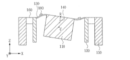
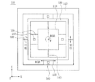
図1は、本発明の実施例による角速度センサの斜視図であり、図2は、図1に図示された角速度センサの平面図であり、図3は、図2に図示されたA−A´線に沿った角速度センサの断面図であり、図4は、図2に図示されたB−B´線に沿った角速度センサの断面図であり、図5は、本発明の実施例による角速度センサの変形例を図示した斜視図である。 1 is a perspective view of an angular velocity sensor according to an embodiment of the present invention, FIG. 2 is a plan view of the angular velocity sensor illustrated in FIG. 1, and FIG. 3 is an AA ′ diagram illustrated in FIG. 4 is a cross-sectional view of the angular velocity sensor along the line, FIG. 4 is a cross-sectional view of the angular velocity sensor along the line BB ′ shown in FIG. 2, and FIG. 5 is an angular velocity sensor according to an embodiment of the present invention. It is the perspective view which illustrated the modification of this.
図1から図4に図示されたように、本実施例による角速度センサ100は、質量体110と、質量体110と離隔されるように質量体110の外側に備えられた第1フレーム120と、X軸方向に質量体110と第1フレーム120とを連結する第1可撓部130と、Y軸方向に質量体110と第1フレーム120とを連結する第2可撓部140と、第1フレーム120と離隔されるように第1フレーム120の外側に備えられた第2フレーム150と、X軸方向に第1フレーム120と第2フレーム150とを連結する第3可撓部160と、Y軸方向に第1フレーム120と第2フレーム150とを連結する第4可撓部170と、を含む構成である。
As shown in FIGS. 1 to 4, the
ここで、第1可撓部130は、Y軸方向の幅w1がZ軸方向の厚さt1より大きく、第2可撓部140は、Z軸方向の厚さt2がX軸方向の幅w2より大きい。また、第3可撓部160は、Z軸方向の厚さt3がY軸方向の幅w3より大きく、第4可撓部170は、X軸方向の幅w4がZ軸方向の厚さt4より大きい。
Here, the first
前記質量体110は、コリオリ力によって変位されるものであり、第1可撓部130及び第2可撓部140を介して第1フレーム120に連結される。ここで、質量体110は、コリオリ力が作用する際に、第1可撓部130の曲げと第2可撓部140の捻りによって第1フレーム120を基準に変位される。この際、質量体110は、第1フレーム120に対してY軸を基準に回転されるが、これについての具体的な説明は後述する。一方、質量体110は、四角柱状に図示されているが、これに限定されるものではない。例えば、図5に図示されたように、質量体110は、円柱状に形成することもでき、その他にも、ファン(Fan)の形状など、当業界に公知された全ての形状に形成することができる。尚、第1可撓部と第4可撓部は、図1〜図4より明らかなように、その形状と質量体及びフレームとの有機的な結合によって、曲げ運動を発生させるビームである。また、第2可撓部と第3可撓部は、図1〜図4より明らかなように、その形状と質量体及びフレームとの有機的な結合によって、「特定方向の変位を発生させるように制限された」捻りを生じさせるヒンジである。
The
前記第1フレーム120は、第1可撓部130及び第2可撓部140を支持して、質量体110を変位することができる空間を確保する役割をし、質量体110が変位される際に基準となる。ここで、第1フレーム120は、質量体110と離隔されるように質量体110の外側に備える。この際、第1フレーム120は、中心に四角柱状の空洞が形成された四角柱状に形成することができるが、これに限定されるものではない。
The
例えば、図5に図示されたように、第1フレーム120は、中心に円柱状の空洞が形成された円柱状に形成することもできる。一方、第1フレーム120は、第3可撓部160及び第4可撓部170を介して第2フレーム150に連結させる。ここで、第1フレーム120は、駆動手段190によって駆動する際に、第3可撓部160の捻りと第4可撓部170の曲げによって第2フレーム150を基準に変位する。この際、第1フレーム120は、第2フレーム150に対してX軸を基準に回転するが、これについての具体的な説明は後述する。
For example, as illustrated in FIG. 5, the
前記第1、2可撓部130、140は、第1フレーム120を基準に質量体110が変位されるように、第1フレーム120と質量体110とを連結する役割をするものであり、第1可撓部130と第2可撓部140は、互いに垂直に形成される。即ち、第1可撓部130は、X軸方向に質量体110と第1フレーム120とを連結し、第2可撓部140は、Y軸方向に質量体110と第1フレーム120とを連結する。この際、第1可撓部130と第2可撓部140は、それぞれ、質量体110と第1フレーム120を両方で連結することができる。但し、図14に図示されたように、第1可撓部130と第2可撓部140は、それぞれ必要に応じて、質量体110と第1フレーム120を一方でのみ連結することもできる。
The first and second
一方、図2から図4に図示されたように、第1可撓部130は、Y軸方向の幅w1がZ軸方向の厚さt1より大きく、第2可撓部140は、Z軸方向の厚さt2がX軸方向の幅w2より大きい。このような第1可撓部130及び第2可撓部140の特性により、質量体110は、第1フレーム120を基準に特定方向にのみ運動することができる。
On the other hand, as illustrated in FIGS. 2 to 4, the first
図6は、図2に図示された質量体の運動可能な方向を図示した平面図であり、図7は、図3に図示された質量体の運動可能な方向を図示した断面図であって、これを参照して質量体110の運動可能な方向について説明する。
6 is a plan view illustrating directions in which the mass body illustrated in FIG. 2 can move, and FIG. 7 is a cross-sectional view illustrating directions in which the mass body illustrated in FIG. 3 can move. The direction in which the
まず、第2可撓部140のZ軸方向の厚さt2がX軸方向の幅w2より大きいため、質量体110は、第1フレーム120に対してX軸を基準に回転したりZ軸方向に並進することが制限されるが、Y軸を基準に相対的に自由に回転することができる(図7参照)。
First, since the thickness t 2 in the Z-axis direction of the second
具体的には、第2可撓部140がY軸を基準に回転する際の剛性に比べX軸を基準に回転する際の剛性が大きいほど、質量体110は、Y軸を基準に自由に回転することができる反面、X軸を基準に回転することが制限される。これと同様に、第2可撓部140がY軸を基準に回転する際の剛性に比べZ軸方向に並進する際の剛性が大きいほど、質量体110は、Y軸を基準に自由に回転することができる反面、Z軸方向に並進することが制限される。従って、第2可撓部140の(X軸を基準に回転する際の剛性またはZ軸方向に並進する際の剛性)/(Y軸を基準に回転する際の剛性)値が増加するほど、質量体110は、第1フレーム120に対してY軸を基準に自由に回転する反面、X軸を基準に回転したりZ軸方向に並進することが制限される。
Specifically, as the rigidity when the second
図2及び図3を参照して、第2可撓部140のZ軸方向の厚さt2、Y軸方向の長さL1及びX軸方向の幅w2と方向毎の剛性との関係をまとめると、次のようになる。
2 and 3, the relationship between the thickness t 2 of the second
(1)第2可撓部140のX軸を基準に回転する際の剛性またはZ軸方向に並進する際の剛性∝ w2×t2 3/L1 3
(1) Rigidity when rotating with respect to the X axis of the second
(2)第2可撓部140のY軸を基準に回転する際の剛性∝ w2 3×t2/L1
(2) rigid α w 2 3 × t 2 / L 1 when rotating based on the Y axis of the second
前記二つの式によると、第2可撓部140の(X軸を基準に回転する際の剛性またはZ軸方向に並進する際の剛性)/(Y軸を基準に回転する際の剛性)値は、(t2/(w2L1))2に比例する。ところが、本実施例による第2可撓部140は、Z軸方向の厚さt2がX軸方向の幅w2より大きいため(t2/(w2L1))2が大きく、従って、第2可撓部140の(X軸を基準に回転する際の剛性またはZ軸方向に並進する際の剛性)/(Y軸を基準に回転する際の剛性)値が増加される。このような第2可撓部140の特性により、質量体110は、第1フレーム120に対してY軸を基準に自由に回転する反面、X軸を基準に回転したりZ軸方向に並進することが制限される。
According to the above two formulas, the value of (the rigidity when rotating with respect to the X axis or the rigidity when translating in the Z axis direction) / (the rigidity when rotating with respect to the Y axis) of the second
一方、第1可撓部130は、長さ方向(X軸方向)の剛性が相対的に非常に高いため、質量体110が第1フレーム120に対してZ軸を基準に回転したりX軸方向に並進することを制限することができる(図6参照)。また、第2可撓部140は、長さ方向(Y軸方向)の剛性が相対的に非常に高いため、質量体110が第1フレーム120に対してY軸方向に並進することを制限することができる(図6参照)。
On the other hand, since the first
結局、上述した第1可撓部130及び第2可撓部140の特性により、質量体110は、第1フレーム120に対してY軸を基準に回転することができるが、X軸またはZ軸を基準に回転したりZ軸、Y軸またはX軸方向に並進することが制限される。即ち、質量体110の運動可能な方向をまとめると、下記の表1のようになる。
Eventually, due to the characteristics of the first

このように、質量体110は、第1フレーム120に対してY軸を基準に回転することができる反面、その他の方向に運動することが制限されるため、質量体110の変位を所望の方向(Y軸を基準に回転)の力に対してのみ発生させることができる。
As described above, the
一方、図8A及び図8Bは、図3に図示された質量体が第1フレームに対してY軸を基準に回転する過程を図示した断面図である。 8A and 8B are cross-sectional views illustrating a process in which the mass body illustrated in FIG. 3 rotates with respect to the first frame with respect to the Y axis.
図8A及び図8Bに図示されたように、質量体110が第1フレーム120に対してY軸を回転軸Rとして回転するため、第1可撓部130には、圧縮応力と引張応力が組み合わされた曲げ応力が発生し、第2可撓部140には、Y軸を基準に捻り応力が発生する。この際、質量体110にトルク(torque)を発生させるために、第2可撓部140は、Z軸方向を基準に質量体110の重心Cより上側に備えることができる。また、図2に図示されたように、質量体110がY軸を基準に正確に回転するように、第2可撓部140は、Y軸方向を基準に質量体110の重心Cに対応する位置に備えることができる。
As shown in FIGS. 8A and 8B, since the
前記第2フレーム150は、第3可撓部160及び第4可撓部170を支持して、第1フレーム120を変位することができる空間を確保する機能を有し、第1フレーム120を変位する際の基準となる。ここで、第2フレーム150は、第1フレーム120と離隔されるように第1フレーム120の外側に備える。この際、第2フレーム150は、中心に四角柱状の空洞が形成された四角柱状に形成することができるが、これに限定されるものではない。例えば、図5に図示されたように、第2フレーム150は、中心に円柱状の空洞が形成された四角柱状に形成することができる。
The
前記第3、4可撓部160、170は、第2フレーム150を基準に第1フレーム120を変位することができるように、第2フレーム150と第1フレーム120とを連結する役割をするものであり、第3可撓部160と第4可撓部170は、互いに垂直に形成される。即ち、第3可撓部160は、X軸方向に第1フレーム120と第2フレーム150とを連結し、第4可撓部170は、Y軸方向に第1フレーム120と第2フレーム150とを連結する。この際、第3可撓部160と第4可撓部170は、それぞれ、第1フレーム120と第2フレーム150を両方で連結することができる。但し、図14に図示されたように、第3可撓部160と第4可撓部170は、それぞれ、必要に応じて、第1フレーム120と第2フレーム150を一方でのみ連結することもできる。
The third and fourth
一方、図2から図4に図示されたように、第3可撓部160は、Z軸方向の厚さt3がY軸方向の幅w3より大きく、第4可撓部170は、X軸方向の幅w4がZ軸方向の厚さt4より大きい。このような第3可撓部160及び第4可撓部170の特性により、第1フレーム120は、第2フレーム150を基準に特定方向にのみ運動することができる。
On the other hand, as illustrated in FIGS. 2 to 4, the third
図9は、図2に図示された第1フレームの運動可能な方向を図示した平面図であり、図10は、図4に図示された第1フレームの運動可能な方向を図示した断面図であって、これを参照して第1フレーム120の運動可能な方向について説明する。
FIG. 9 is a plan view illustrating directions in which the first frame illustrated in FIG. 2 can move, and FIG. 10 is a cross-sectional view illustrating directions in which the first frame illustrated in FIG. 4 can move. The direction in which the
まず、第3可撓部160のZ軸方向の厚さt3がY軸方向の幅w3より大きいため、第1フレーム120は、第2フレーム150に対してY軸を基準に回転したりZ軸方向に並進することが制限される反面、X軸を基準に相対的に自由に回転することができる(図10参照)。
First, since the thickness t 3 in the Z-axis direction of the third
具体的には、第3可撓部160がX軸を基準に回転する際の剛性に比べY軸を基準に回転する際の剛性が大きいほど、第1フレーム120は、X軸を基準に自由に回転することができる反面、Y軸を基準に回転することが制限される。これと同様に、第3可撓部160がX軸を基準に回転する際の剛性に比べZ軸方向に並進する際の剛性が大きいほど、第1フレーム120は、X軸を基準に自由に回転することができる反面、Z軸方向に並進することが制限される。従って、第3可撓部160の(Y軸を基準に回転する際の剛性またはZ軸方向に並進する際の剛性)/(X軸を基準に回転する際の剛性)値が増加するほど、第1フレーム120は、第2フレーム150に対してX軸を基準に自由に回転する反面、Y軸を基準に回転したりZ軸方向に並進することが制限される。
Specifically, as the rigidity when the third
図2から図4を参照して、第3可撓部160のZ軸方向の厚さt3、X軸方向の長さL2及びY軸方向の幅w3と方向毎の剛性との関係をまとめると、次のようになる。
2 to 4, the relationship between the thickness t 3 in the Z-axis direction, the length L 2 in the X-axis direction, the width w 3 in the Y-axis direction, and the rigidity in each direction of the third
(1)第3可撓部160のY軸を基準に回転する際の剛性またはZ軸方向に並進する際の剛性∝ w3×t3 3/L2 3
(1) Rigidity when rotating with respect to the Y-axis of the third
(2)第3可撓部160のX軸を基準に回転する際の剛性∝ w3 3×t3/L2 (2) Rigidity when rotating with respect to the X axis of the third flexible portion 160 w 3 3 × t 3 / L 2
前記二つの式によると、第3可撓部160の(Y軸を基準に回転する際の剛性またはZ軸方向に並進する際の剛性)/(X軸を基準に回転する際の剛性)値は、(t3/(w3L2))2に比例する。ところが、本実施例による第3可撓部160は、Z軸方向の厚さt3がY軸方向の幅w3より大きいため(t3/(w3L2))2が大きく、従って、第3可撓部160の(Y軸を基準に回転する際の剛性またはZ軸方向に並進する際の剛性)/(X軸を基準に回転する際の剛性)値は増加される。このような第3可撓部160の特性により、第1フレーム120は、第2フレーム150に対してX軸を基準に自由に回転する反面、Y軸を基準に回転したりZ軸方向に並進することが制限される。
According to the above two formulas, the value of (the rigidity when rotating with respect to the Y axis or the rigidity when translating in the Z axis direction) / (the rigidity when rotating with respect to the X axis) of the third
一方、第4可撓部170は、長さ方向(Y軸方向)の剛性が相対的に非常に高いため、第1フレーム120が第2フレーム150に対してZ軸を基準に回転したりY軸方向に並進することを制限することができる(図9参照)。また、第3可撓部160は、長さ方向(X軸方向)の剛性が相対的に非常に高いため、第1フレーム120が第2フレーム150に対してX軸方向に並進することを制限することができる(図9参照)。
On the other hand, since the fourth
結局、上述した第3可撓部160及び第4可撓部170の特性により、第1フレーム120は、第2フレーム150に対してX軸を基準に回転することができるが、Y軸またはZ軸を基準に回転したりZ軸、Y軸またはX軸方向に並進することが制限される。即ち、第1フレーム120の運動可能な方向をまとめると、下記の表2のようになる。
Eventually, due to the characteristics of the third
このように、第1フレーム120は、第2フレーム150に対してX軸を基準に回転することができる反面、その他の方向に運動することが制限されるため、第1フレーム120の変位を所望の方向(X軸を基準に回転)の力に対してのみ発生させることができる。
As described above, the
一方、図11A及び図11Bは、図4に図示された第1フレームが第2フレームに対してX軸を基準に回転する過程を図示した断面図である。 11A and 11B are cross-sectional views illustrating a process in which the first frame illustrated in FIG. 4 rotates with respect to the second frame with respect to the X axis.
図11A及び図11Bに図示されたように、第1フレーム120が第2フレーム150に対してX軸を基準に回転するため、第3可撓部160には、X軸を基準に捻り応力が発生し、第4可撓部170には、圧縮応力と引張応力が組み合わされた曲げ応力が発生する。
11A and 11B, since the
さらに、図2に図示されたように、XY平面を基準として、第1可撓部130が相対的に広い反面、第2可撓部140が相対的に狭いため、第1可撓部130には、質量体110の変位を検知する検知手段180を備えることができる。ここで、検知手段180は、Y軸を基準に回転する質量体110の変位を検知することができる。この際、検知手段180は、特に限定されるものではないが、圧電方式、ピエゾ抵抗方式、静電容量方式、光学方式などを用いて形成することができる。
Further, as illustrated in FIG. 2, the first
また、XY平面を基準として、第4可撓部170は相対的に広い反面、第3可撓部160は相対的に狭いため、第4可撓部170には、第1フレーム120を駆動させる駆動手段190を備えることができる。ここで、駆動手段190は、第1フレーム120をX軸を基準に回転するように駆動させることができる。この際、駆動手段190は、特に限定されるものではないが、圧電方式、静電容量方式などを用いて形成することができる。
Further, the fourth
一方、上述の構造的特性を利用して、本実施例による角速度センサ100は、角速度を測定することができる。
On the other hand, the
図12から図13は、本実施例による角速度センサが角速度を測定する過程を図示した断面図であり、これを参照して、角速度を測定する過程について説明する。 12 to 13 are cross-sectional views illustrating a process of measuring the angular velocity by the angular velocity sensor according to the present embodiment, and the process of measuring the angular velocity will be described with reference to this.
まず、図12A及び図12Bに図示されたように、駆動手段190を用いて第1フレーム120を第2フレーム150に対してX軸を基準に回転させる(駆動モード)。ここで、質量体110は、第1フレーム120とともにX軸を基準に回転されながら振動し、振動によって質量体110には、Y軸方向に速度VYが発生する。この際、Z軸を基準とする角速度ΩZが質量体110に印加されると、X軸方向にコリオリ力FXが発生する。
First, as shown in FIGS. 12A and 12B, the
このようなコリオリ力FXにより、図13A及び図13Bに図示されたように、質量体110は、第1フレーム120に対してY軸を基準に回転しながら変位され、検知手段180が質量体110の変位を検知する(検知モード)。質量体110の変位を検知することにより、コリオリ力FXを算出することができ、前記コリオリ力FXを利用してZ軸を基準とする角速度ΩZを測定することができる。
Such Coriolis force F X, as illustrated in FIGS. 13A and 13B, the
一方、上述した第1可撓部130及び第2可撓部140の特性により、質量体110は、第1フレーム120に対してY軸を基準にのみ回転することができる。従って、図12A及び図12Bに図示されたように、駆動手段190を用いて第1フレーム120を第2フレーム150に対してX軸を基準に回転させても、質量体110は、第1フレーム120に対してX軸を基準に回転されない。また、上述した第3可撓部160及び第4可撓部170の特性により、第1フレーム120は、第2フレーム150に対してX軸を基準にのみ回転することができる。
On the other hand, due to the characteristics of the first
従って、図13A及び図13Bに図示されたように、検知手段180を用いて質量体110の変位を検知する際に、X軸方向のコリオリ力FXが作用しても、第1フレーム120は、第2フレーム150に対してY軸を基準に回転せず、質量体110のみが第1フレーム120に対してY軸方向に回転する。このように、本実施例による角速度センサ100は、第1フレーム120及び第2フレーム150を備えて質量体110の駆動変位と検知変位を個別的に発生させて、特定方向に対してのみ質量体110と第1フレーム120が運動できるように、第1、2、3、4可撓部130、140、160、170を形成する。従って、駆動モードと検知モードとの間の干渉を除去して回路増幅比の上昇による感度の向上を実現することができ、製作誤差による影響を低減させて、収率を向上させることができる効果がある。
Therefore, as shown in FIGS. 13A and 13B, in detecting displacement of the
以上、本発明を具体的な実施例に基づいて詳細に説明したが、これは本発明を具体的に説明するためのものであり、本発明はこれに限定されず、該当分野における通常の知識を有する者であれば、本発明の技術的思想内にての変形や改良が可能であることは明白であろう。特に、本発明は、「X軸」、「Y軸」及び「Z軸」を基準として説明したが、これは説明の便宜のために定義したものに過ぎないため、本発明の権利範囲がこれに制限されるものではない。 As described above, the present invention has been described in detail based on the specific embodiments. However, the present invention is only for explaining the present invention, and the present invention is not limited thereto. It will be apparent to those skilled in the art that modifications and improvements within the technical idea of the present invention are possible. In particular, the present invention has been described with reference to the “X-axis”, “Y-axis”, and “Z-axis”. However, this is merely defined for convenience of description, and the scope of rights of the present invention is not limited thereto. It is not limited to.
本発明の単純な変形乃至変更はいずれも本発明の領域に属するものであり、本発明の具体的な保護範囲は添付の特許請求の範囲により明確になるであろう。 All simple variations and modifications of the present invention belong to the scope of the present invention, and the specific scope of protection of the present invention will be apparent from the appended claims.
本発明は、角速度センサに適用可能である。 The present invention is applicable to an angular velocity sensor.
100 角速度センサ
110 質量体
120 第1フレーム
130 第1可撓部
140 第2可撓部
150 第2フレーム
160 第3可撓部
170 第4可撓部
180 検知手段
190 駆動手段
C 質量体の重心
t1 第1可撓部の厚さ
w1 第1可撓部の幅
t2 第2可撓部の厚さ
L1 第2可撓部の長さ
w2 第2可撓部の幅
R 回転軸
t3 第3可撓部の厚さ
w3 第3可撓部の幅
L2 第3可撓部の長さ
t4 第4可撓部の厚さ
w4 第4可撓部の幅
100
Claims (20)
前記質量体と離隔されるように前記質量体の外側に備えられた第1フレームと、
前記質量体と前記第1フレームとを連結する第1可撓部と、
前記質量体と前記第1フレームとを連結する第2可撓部と、
前記第1フレームと離隔されるように前記第1フレームの外側に備えられた第2フレームと、
前記第1フレームと前記第2フレームとを連結する第3可撓部と、
前記第1フレームと前記第2フレームとを連結する第4可撓部と、を含み、
前記第1可撓部はY軸方向の幅がZ軸方向の厚さより大きく、
前記第2可撓部はZ軸方向の厚さがX軸方向の幅より大きく、
前記第3可撓部はZ軸方向の厚さがY軸方向の幅より大きく、
前記第4可撓部はX軸方向の幅がZ軸方向の厚さより大きく、
前記第1可撓部及び第4可撓部はビームであり、
前記第2可撓部は、前記質量体がY軸を中心に回転するようにし、前記質量体のX軸基準の回転とZ軸方向の変位を制限するヒンジであり、
前記第3可撓部は、前記第1フレームがX軸を中心に回転するようにし、前記第1フレームのY軸基準の回転とZ軸方向の変位を制限するヒンジであることを特徴とする角速度センサ。 Mass body,
A first frame provided outside the mass body so as to be separated from the mass body;
A first flexible part connecting the mass body and the first frame;
A second flexible part connecting the mass body and the first frame;
A second frame provided outside the first frame to be spaced apart from the first frame;
A third flexible part connecting the first frame and the second frame;
A fourth flexible portion connecting the first frame and the second frame,
The first flexible portion has a width in the Y-axis direction larger than a thickness in the Z-axis direction,
The second flexible part has a thickness in the Z-axis direction larger than a width in the X-axis direction,
The third flexible part has a thickness in the Z-axis direction larger than a width in the Y-axis direction,
The fourth flexible part has a width in the X-axis direction larger than a thickness in the Z-axis direction,
The first flexible part and the fourth flexible part are beams,
The second flexible portion is a hinge that allows the mass body to rotate about the Y axis and restricts rotation of the mass body with respect to the X axis and displacement in the Z axis direction ,
The third flexible part is a hinge that allows the first frame to rotate about the X axis and restricts the rotation of the first frame based on the Y axis and the displacement in the Z axis direction. Angular velocity sensor.
前記第3可撓部と第4可撓部は互いに直交する方向に配置されることを特徴とする請求項1に記載の角速度センサ。 The first flexible part and the second flexible part are arranged in directions orthogonal to each other,
The angular velocity sensor according to claim 1, wherein the third flexible portion and the fourth flexible portion are arranged in directions orthogonal to each other.
前記第2可撓部は、Y軸方向に前記質量体と前記第1フレームとを連結し、
前記第3可撓部は、X軸方向に前記第1フレームと前記第2フレームとを連結し、
前記第4可撓部は、Y軸方向に前記第1フレームと前記第2フレームとを連結することを特徴とする請求項1に記載の角速度センサ。 The first flexible portion connects the mass body and the first frame in the X-axis direction,
The second flexible portion connects the mass body and the first frame in the Y-axis direction,
The third flexible part connects the first frame and the second frame in the X-axis direction,
The angular velocity sensor according to claim 1, wherein the fourth flexible portion connects the first frame and the second frame in the Y-axis direction.
Applications Claiming Priority (2)
| Application Number | Priority Date | Filing Date | Title |
|---|---|---|---|
| KR10-2012-0056905 | 2012-05-29 | ||
| KR1020120056905A KR101299731B1 (en) | 2012-05-29 | 2012-05-29 | Angular velocity sensor |
Publications (2)
| Publication Number | Publication Date |
|---|---|
| JP2013246180A JP2013246180A (en) | 2013-12-09 |
| JP5968265B2 true JP5968265B2 (en) | 2016-08-10 |
Family
ID=49221177
Family Applications (1)
| Application Number | Title | Priority Date | Filing Date |
|---|---|---|---|
| JP2013113521A Expired - Fee Related JP5968265B2 (en) | 2012-05-29 | 2013-05-29 | Angular velocity sensor |
Country Status (3)
| Country | Link |
|---|---|
| US (2) | US8919198B2 (en) |
| JP (1) | JP5968265B2 (en) |
| KR (1) | KR101299731B1 (en) |
Families Citing this family (8)
| Publication number | Priority date | Publication date | Assignee | Title |
|---|---|---|---|---|
| KR101299731B1 (en) | 2012-05-29 | 2013-08-22 | 삼성전기주식회사 | Angular velocity sensor |
| KR101388814B1 (en) * | 2012-09-11 | 2014-04-23 | 삼성전기주식회사 | Angular Velocity Sensor |
| KR101366990B1 (en) * | 2012-12-28 | 2014-02-24 | 삼성전기주식회사 | Angular velocity sensor |
| KR101531093B1 (en) * | 2013-07-31 | 2015-06-23 | 삼성전기주식회사 | Acceleration Sensor and Angular Velocity Sensor |
| KR101540154B1 (en) * | 2013-10-04 | 2015-07-28 | 삼성전기주식회사 | Angular Velocity Sensor and Manufacturing Method of the same |
| KR102070229B1 (en) * | 2014-11-14 | 2020-03-02 | 삼성전기주식회사 | Angular Velocity Sensor |
| KR101659207B1 (en) | 2015-02-05 | 2016-09-22 | 삼성전기주식회사 | Angular Velocity Sensor |
| CN109489648B (en) * | 2018-12-30 | 2022-07-01 | 瑞声声学科技(深圳)有限公司 | Gyroscope |
Family Cites Families (31)
| Publication number | Priority date | Publication date | Assignee | Title |
|---|---|---|---|---|
| US4598585A (en) | 1984-03-19 | 1986-07-08 | The Charles Stark Draper Laboratory, Inc. | Planar inertial sensor |
| US5205171A (en) * | 1991-01-11 | 1993-04-27 | Northrop Corporation | Miniature silicon accelerometer and method |
| JPH06160421A (en) | 1992-11-18 | 1994-06-07 | Murata Mfg Co Ltd | Oscillatory type acceleration sensor |
| JPH0783667A (en) | 1993-09-14 | 1995-03-28 | Toshiba Corp | Angular velocity sensor |
| JP3409565B2 (en) * | 1996-03-01 | 2003-05-26 | 日産自動車株式会社 | Self-diagnosis method of angular velocity sensor |
| US5992233A (en) * | 1996-05-31 | 1999-11-30 | The Regents Of The University Of California | Micromachined Z-axis vibratory rate gyroscope |
| JPH1089968A (en) | 1996-09-12 | 1998-04-10 | Murata Mfg Co Ltd | Angular velocity sensor |
| WO1999019689A1 (en) | 1997-10-14 | 1999-04-22 | Omron Corporation | Angular velocity sensor |
| JP2000088579A (en) | 1998-09-14 | 2000-03-31 | Denso Corp | Angular velocity sensor and manufacture thereof |
| US6426538B1 (en) * | 2001-01-16 | 2002-07-30 | Honeywell International Inc. | Suspended micromachined structure |
| US6964195B2 (en) * | 2004-01-30 | 2005-11-15 | Bei Technologies, Inc. | Micromachined vibratory gyroscope and method with electronic coupling |
| US8726730B1 (en) * | 2011-12-14 | 2014-05-20 | Sandia Corporation | Optically transduced MEMS gyro device |
| JP4929918B2 (en) * | 2006-08-21 | 2012-05-09 | パナソニック株式会社 | Compound sensor |
| EP2113744A4 (en) * | 2007-02-20 | 2013-04-17 | Panasonic Corp | INERTIAL FORCE SENSOR AND COMPOSITE SENSOR FOR DETECTION OF INERTIA FORCE |
| JP5186885B2 (en) * | 2007-11-07 | 2013-04-24 | 大日本印刷株式会社 | Mask pattern correction method and acceleration sensor and angular velocity sensor manufacturing method using the same |
| KR101149266B1 (en) * | 2007-12-19 | 2012-07-20 | 가부시키가이샤 무라타 세이사쿠쇼 | Angular velocity sensor |
| JP2010043929A (en) | 2008-08-12 | 2010-02-25 | Yamaha Corp | Motion sensor |
| US20100133852A1 (en) * | 2008-11-21 | 2010-06-03 | Preus Robert W | Vertical axis wind turbine with variable area |
| DE102009001244A1 (en) * | 2009-02-27 | 2010-09-02 | Sensordynamics Ag | Micro gyroscope for determining rotational movements about an x, y or z axis |
| JP5652775B2 (en) * | 2009-05-29 | 2015-01-14 | トレックス・セミコンダクター株式会社 | Acceleration sensor element and acceleration sensor having the same |
| FR2947333B1 (en) * | 2009-06-30 | 2011-07-29 | Thales Sa | MICRO-FACTORY GYROSCOPE WITH DETECTION IN PLATE PLATE PLAN |
| KR101119283B1 (en) | 2009-12-22 | 2012-06-05 | 삼성전기주식회사 | Inertial sensor and producing method thereof |
| CN102334008B (en) * | 2010-01-12 | 2015-07-15 | 索尼公司 | Angular velocity sensor, electronic device, and method for detecting angular velocity |
| US8453504B1 (en) * | 2010-01-23 | 2013-06-04 | Minyao Mao | Angular rate sensor with suppressed linear acceleration response |
| US8459111B1 (en) * | 2010-01-23 | 2013-06-11 | Minyao Mao | Angular rate sensor with suppressed linear acceleration response |
| US9354061B2 (en) * | 2011-03-31 | 2016-05-31 | Ramot At Tel Aviv University Ltd. | Compliant structures with time-varying moment of inertia |
| US8689632B2 (en) * | 2012-01-17 | 2014-04-08 | Freescale Semiconductor, Inc. | Fully decoupled lateral axis gyroscope with thickness-insensitive Z-axis spring and symmetric teeter totter sensing element |
| KR101299731B1 (en) | 2012-05-29 | 2013-08-22 | 삼성전기주식회사 | Angular velocity sensor |
| KR101388814B1 (en) * | 2012-09-11 | 2014-04-23 | 삼성전기주식회사 | Angular Velocity Sensor |
| KR101461277B1 (en) * | 2012-09-21 | 2014-11-12 | 삼성전기주식회사 | Micro Electro Mechanical Systems Component |
| KR101366990B1 (en) * | 2012-12-28 | 2014-02-24 | 삼성전기주식회사 | Angular velocity sensor |
-
2012
- 2012-05-29 KR KR1020120056905A patent/KR101299731B1/en not_active Expired - Fee Related
-
2013
- 2013-05-28 US US13/903,782 patent/US8919198B2/en not_active Expired - Fee Related
- 2013-05-29 JP JP2013113521A patent/JP5968265B2/en not_active Expired - Fee Related
-
2014
- 2014-11-21 US US14/550,838 patent/US9631927B2/en not_active Expired - Fee Related
Also Published As
| Publication number | Publication date |
|---|---|
| JP2013246180A (en) | 2013-12-09 |
| KR101299731B1 (en) | 2013-08-22 |
| US8919198B2 (en) | 2014-12-30 |
| US9631927B2 (en) | 2017-04-25 |
| US20160178373A1 (en) | 2016-06-23 |
| US20130319114A1 (en) | 2013-12-05 |
Similar Documents
| Publication | Publication Date | Title |
|---|---|---|
| JP5968265B2 (en) | Angular velocity sensor | |
| JP5714071B2 (en) | Angular velocity sensor | |
| US20160363445A1 (en) | Configuration to reduce non-linear motion | |
| KR101366990B1 (en) | Angular velocity sensor | |
| KR101565684B1 (en) | Detector module for MEMS Sensor and MEMS Sensor having the same | |
| KR101531093B1 (en) | Acceleration Sensor and Angular Velocity Sensor | |
| JP5864679B2 (en) | Sensor detection module and angular velocity sensor including the same | |
| US9035400B2 (en) | Micro electro mechanical systems device | |
| KR101461332B1 (en) | Sensing Module and Angular Velocity Sensor having the same | |
| JP5816322B2 (en) | Sensor | |
| KR101420534B1 (en) | Angular Velocity Sensor | |
| KR101521702B1 (en) | Angular Velocity Sensor | |
| KR101540162B1 (en) | Angular Velocity Sensor | |
| KR101299730B1 (en) | Sensor | |
| US20150052998A1 (en) | Angular velocity sensor | |
| KR102070229B1 (en) | Angular Velocity Sensor | |
| KR20160085114A (en) | Angular velocity sensor |
Legal Events
| Date | Code | Title | Description |
|---|---|---|---|
| A977 | Report on retrieval |
Free format text: JAPANESE INTERMEDIATE CODE: A971007 Effective date: 20140326 |
|
| A131 | Notification of reasons for refusal |
Free format text: JAPANESE INTERMEDIATE CODE: A131 Effective date: 20140401 |
|
| A521 | Request for written amendment filed |
Free format text: JAPANESE INTERMEDIATE CODE: A523 Effective date: 20140626 |
|
| A601 | Written request for extension of time |
Free format text: JAPANESE INTERMEDIATE CODE: A601 Effective date: 20140701 |
|
| A602 | Written permission of extension of time |
Free format text: JAPANESE INTERMEDIATE CODE: A602 Effective date: 20140704 |
|
| A521 | Request for written amendment filed |
Free format text: JAPANESE INTERMEDIATE CODE: A523 Effective date: 20140725 |
|
| A02 | Decision of refusal |
Free format text: JAPANESE INTERMEDIATE CODE: A02 Effective date: 20141111 |
|
| A521 | Request for written amendment filed |
Free format text: JAPANESE INTERMEDIATE CODE: A523 Effective date: 20150311 |
|
| A911 | Transfer to examiner for re-examination before appeal (zenchi) |
Free format text: JAPANESE INTERMEDIATE CODE: A911 Effective date: 20150422 |
|
| A912 | Re-examination (zenchi) completed and case transferred to appeal board |
Free format text: JAPANESE INTERMEDIATE CODE: A912 Effective date: 20150626 |
|
| A521 | Request for written amendment filed |
Free format text: JAPANESE INTERMEDIATE CODE: A523 Effective date: 20160415 |
|
| A61 | First payment of annual fees (during grant procedure) |
Free format text: JAPANESE INTERMEDIATE CODE: A61 Effective date: 20160705 |
|
| R150 | Certificate of patent or registration of utility model |
Ref document number: 5968265 Country of ref document: JP Free format text: JAPANESE INTERMEDIATE CODE: R150 |
|
| R250 | Receipt of annual fees |
Free format text: JAPANESE INTERMEDIATE CODE: R250 |
|
| R250 | Receipt of annual fees |
Free format text: JAPANESE INTERMEDIATE CODE: R250 |
|
| LAPS | Cancellation because of no payment of annual fees |