JP5967876B2 - Liquid discharge head and manufacturing method thereof - Google Patents
Liquid discharge head and manufacturing method thereof Download PDFInfo
- Publication number
- JP5967876B2 JP5967876B2 JP2011161866A JP2011161866A JP5967876B2 JP 5967876 B2 JP5967876 B2 JP 5967876B2 JP 2011161866 A JP2011161866 A JP 2011161866A JP 2011161866 A JP2011161866 A JP 2011161866A JP 5967876 B2 JP5967876 B2 JP 5967876B2
- Authority
- JP
- Japan
- Prior art keywords
- liquid
- substrate
- etching
- discharge head
- liquid supply
- Prior art date
- Legal status (The legal status is an assumption and is not a legal conclusion. Google has not performed a legal analysis and makes no representation as to the accuracy of the status listed.)
- Active
Links
- 239000007788 liquid Substances 0.000 title claims description 153
- 238000004519 manufacturing process Methods 0.000 title claims description 22
- 238000005530 etching Methods 0.000 claims description 75
- 239000000758 substrate Substances 0.000 claims description 65
- 238000000034 method Methods 0.000 claims description 45
- 238000001312 dry etching Methods 0.000 claims description 34
- 238000009623 Bosch process Methods 0.000 claims description 15
- 238000007599 discharging Methods 0.000 claims description 9
- 230000002093 peripheral effect Effects 0.000 claims description 7
- 238000011161 development Methods 0.000 claims description 5
- 238000010438 heat treatment Methods 0.000 claims description 5
- 230000000149 penetrating effect Effects 0.000 claims description 4
- 235000020637 scallop Nutrition 0.000 description 14
- 241000237509 Patinopecten sp. Species 0.000 description 13
- 239000000463 material Substances 0.000 description 12
- 230000005499 meniscus Effects 0.000 description 12
- 238000000576 coating method Methods 0.000 description 8
- 239000011248 coating agent Substances 0.000 description 7
- 229920005989 resin Polymers 0.000 description 7
- 239000011347 resin Substances 0.000 description 7
- 230000001681 protective effect Effects 0.000 description 6
- 229910052731 fluorine Inorganic materials 0.000 description 5
- 239000011737 fluorine Substances 0.000 description 5
- 238000001020 plasma etching Methods 0.000 description 5
- YCKRFDGAMUMZLT-UHFFFAOYSA-N Fluorine atom Chemical compound [F] YCKRFDGAMUMZLT-UHFFFAOYSA-N 0.000 description 4
- XUIMIQQOPSSXEZ-UHFFFAOYSA-N Silicon Chemical compound [Si] XUIMIQQOPSSXEZ-UHFFFAOYSA-N 0.000 description 3
- 238000010586 diagram Methods 0.000 description 3
- 238000012545 processing Methods 0.000 description 3
- 229910052710 silicon Inorganic materials 0.000 description 3
- 239000010703 silicon Substances 0.000 description 3
- 238000004528 spin coating Methods 0.000 description 3
- 238000005507 spraying Methods 0.000 description 3
- 238000000018 DNA microarray Methods 0.000 description 2
- 238000005266 casting Methods 0.000 description 2
- 239000000919 ceramic Substances 0.000 description 2
- 238000004891 communication Methods 0.000 description 2
- 150000001875 compounds Chemical class 0.000 description 2
- 239000011521 glass Substances 0.000 description 2
- 150000002500 ions Chemical class 0.000 description 2
- 239000002184 metal Substances 0.000 description 2
- 239000002245 particle Substances 0.000 description 2
- 238000007639 printing Methods 0.000 description 2
- 230000003252 repetitive effect Effects 0.000 description 2
- 239000004925 Acrylic resin Substances 0.000 description 1
- 229920000178 Acrylic resin Polymers 0.000 description 1
- 241000237503 Pectinidae Species 0.000 description 1
- 229910004490 TaAl Inorganic materials 0.000 description 1
- BOTDANWDWHJENH-UHFFFAOYSA-N Tetraethyl orthosilicate Chemical compound CCO[Si](OCC)(OCC)OCC BOTDANWDWHJENH-UHFFFAOYSA-N 0.000 description 1
- 230000015572 biosynthetic process Effects 0.000 description 1
- 238000006243 chemical reaction Methods 0.000 description 1
- 230000000052 comparative effect Effects 0.000 description 1
- 239000000470 constituent Substances 0.000 description 1
- 238000000708 deep reactive-ion etching Methods 0.000 description 1
- 238000000151 deposition Methods 0.000 description 1
- 230000008021 deposition Effects 0.000 description 1
- 238000013461 design Methods 0.000 description 1
- 238000007598 dipping method Methods 0.000 description 1
- 230000000694 effects Effects 0.000 description 1
- 239000012776 electronic material Substances 0.000 description 1
- 239000003822 epoxy resin Substances 0.000 description 1
- 239000004744 fabric Substances 0.000 description 1
- 239000000835 fiber Substances 0.000 description 1
- NBVXSUQYWXRMNV-UHFFFAOYSA-N fluoromethane Chemical compound FC NBVXSUQYWXRMNV-UHFFFAOYSA-N 0.000 description 1
- 238000005187 foaming Methods 0.000 description 1
- 230000009477 glass transition Effects 0.000 description 1
- 230000020169 heat generation Effects 0.000 description 1
- 239000010985 leather Substances 0.000 description 1
- 235000014666 liquid concentrate Nutrition 0.000 description 1
- 230000000116 mitigating effect Effects 0.000 description 1
- 239000000203 mixture Substances 0.000 description 1
- QVEIBLDXZNGPHR-UHFFFAOYSA-N naphthalene-1,4-dione;diazide Chemical class [N-]=[N+]=[N-].[N-]=[N+]=[N-].C1=CC=C2C(=O)C=CC(=O)C2=C1 QVEIBLDXZNGPHR-UHFFFAOYSA-N 0.000 description 1
- 229920003986 novolac Polymers 0.000 description 1
- 239000004033 plastic Substances 0.000 description 1
- 229920000647 polyepoxide Polymers 0.000 description 1
- 238000009751 slip forming Methods 0.000 description 1
- 239000007921 spray Substances 0.000 description 1
- 239000002023 wood Substances 0.000 description 1
Images


Classifications
-
- B—PERFORMING OPERATIONS; TRANSPORTING
- B41—PRINTING; LINING MACHINES; TYPEWRITERS; STAMPS
- B41J—TYPEWRITERS; SELECTIVE PRINTING MECHANISMS, i.e. MECHANISMS PRINTING OTHERWISE THAN FROM A FORME; CORRECTION OF TYPOGRAPHICAL ERRORS
- B41J2/00—Typewriters or selective printing mechanisms characterised by the printing or marking process for which they are designed
- B41J2/005—Typewriters or selective printing mechanisms characterised by the printing or marking process for which they are designed characterised by bringing liquid or particles selectively into contact with a printing material
- B41J2/01—Ink jet
- B41J2/135—Nozzles
- B41J2/16—Production of nozzles
- B41J2/1601—Production of bubble jet print heads
- B41J2/1603—Production of bubble jet print heads of the front shooter type
-
- B—PERFORMING OPERATIONS; TRANSPORTING
- B41—PRINTING; LINING MACHINES; TYPEWRITERS; STAMPS
- B41J—TYPEWRITERS; SELECTIVE PRINTING MECHANISMS, i.e. MECHANISMS PRINTING OTHERWISE THAN FROM A FORME; CORRECTION OF TYPOGRAPHICAL ERRORS
- B41J2/00—Typewriters or selective printing mechanisms characterised by the printing or marking process for which they are designed
- B41J2/005—Typewriters or selective printing mechanisms characterised by the printing or marking process for which they are designed characterised by bringing liquid or particles selectively into contact with a printing material
- B41J2/01—Ink jet
- B41J2/135—Nozzles
- B41J2/16—Production of nozzles
- B41J2/1621—Manufacturing processes
- B41J2/1626—Manufacturing processes etching
- B41J2/1628—Manufacturing processes etching dry etching
-
- B—PERFORMING OPERATIONS; TRANSPORTING
- B41—PRINTING; LINING MACHINES; TYPEWRITERS; STAMPS
- B41J—TYPEWRITERS; SELECTIVE PRINTING MECHANISMS, i.e. MECHANISMS PRINTING OTHERWISE THAN FROM A FORME; CORRECTION OF TYPOGRAPHICAL ERRORS
- B41J2/00—Typewriters or selective printing mechanisms characterised by the printing or marking process for which they are designed
- B41J2/005—Typewriters or selective printing mechanisms characterised by the printing or marking process for which they are designed characterised by bringing liquid or particles selectively into contact with a printing material
- B41J2/01—Ink jet
- B41J2/135—Nozzles
- B41J2/16—Production of nozzles
- B41J2/1621—Manufacturing processes
- B41J2/1631—Manufacturing processes photolithography
-
- B—PERFORMING OPERATIONS; TRANSPORTING
- B41—PRINTING; LINING MACHINES; TYPEWRITERS; STAMPS
- B41J—TYPEWRITERS; SELECTIVE PRINTING MECHANISMS, i.e. MECHANISMS PRINTING OTHERWISE THAN FROM A FORME; CORRECTION OF TYPOGRAPHICAL ERRORS
- B41J2/00—Typewriters or selective printing mechanisms characterised by the printing or marking process for which they are designed
- B41J2/005—Typewriters or selective printing mechanisms characterised by the printing or marking process for which they are designed characterised by bringing liquid or particles selectively into contact with a printing material
- B41J2/01—Ink jet
- B41J2/135—Nozzles
- B41J2/16—Production of nozzles
- B41J2/1621—Manufacturing processes
- B41J2/164—Manufacturing processes thin film formation
- B41J2/1645—Manufacturing processes thin film formation thin film formation by spincoating
-
- Y—GENERAL TAGGING OF NEW TECHNOLOGICAL DEVELOPMENTS; GENERAL TAGGING OF CROSS-SECTIONAL TECHNOLOGIES SPANNING OVER SEVERAL SECTIONS OF THE IPC; TECHNICAL SUBJECTS COVERED BY FORMER USPC CROSS-REFERENCE ART COLLECTIONS [XRACs] AND DIGESTS
- Y10—TECHNICAL SUBJECTS COVERED BY FORMER USPC
- Y10T—TECHNICAL SUBJECTS COVERED BY FORMER US CLASSIFICATION
- Y10T29/00—Metal working
- Y10T29/49—Method of mechanical manufacture
- Y10T29/49401—Fluid pattern dispersing device making, e.g., ink jet
Landscapes
- Engineering & Computer Science (AREA)
- Manufacturing & Machinery (AREA)
- Particle Formation And Scattering Control In Inkjet Printers (AREA)
Description
本発明は液体を吐出するための液体吐出ヘッド及びその製造方法に関する。 The present invention relates to a liquid discharge head for discharging liquid and a method for manufacturing the same.
インクジェット記録ヘッドにおけるインク供給口の形成方法として、特許文献1に記載されているように、基板裏面よりドライエッチングを用いて形成する方法がある。インクジェット記録ヘッドのようにウエハ内に多数のインク供給口を形成する製品の場合、ドライエッチングを用いてインク供給口を形成することにより、インク供給口の開口幅の広がりを抑えることができる。
As a method for forming an ink supply port in an ink jet recording head, there is a method of forming by using dry etching from the back surface of a substrate, as described in
このように基板内に面方向に対して垂直な形状でインク供給口を形成するためには、特許文献2に記載されるように、コーティングとエッチングを交互に行うボッシュプロセス(BOSCH(TM)プロセスとも称す)を用いることが多い。例えば、ボッシュプロセスを用いた反応イオンエッチング(DRIE)により、垂直な形状で深くインク供給口を形成することができる。ボッシュプロセスの概要は、(1)フッ素系材料によるコーティング膜形成プロセス、(2)底面コーティング膜除去プロセス、(3)基板エッチングプロセスの主に3プロセスを繰り返すことで基板内に垂直性の高い形状を形成する。より詳細に以下に説明する。(1)フッ素系材料としてフッ化炭素ガスによって表面上に(CF2)n系のコーティング膜を形成する。このコーティング膜によって、後続のエッチングによる側壁のエッチングが防止される。(2)エッチングガスとフッ素系材料を交換し、発生したイオンを掘り込まれた底面に向かわせる。底面のコーティング膜は前記イオンにより破られる。(3)エッチャントとして、反応性エッチングガスがSF6からフッ素ラジカルと荷電粒子を作り出し、揮発性のSiFXを形成する。このラジカルが化学的又は物理的に基板をエッチングして、基板材料を除去する。 In order to form the ink supply port in a shape perpendicular to the surface direction in the substrate in this way, as described in Patent Document 2, a Bosch process (BOSCH (TM) process) in which coating and etching are performed alternately. Often used). For example, the ink supply port can be deeply formed in a vertical shape by reactive ion etching (DRIE) using a Bosch process. The outline of the Bosch process is as follows: (1) Coating film formation process with fluorine-based material, (2) Bottom coating film removal process, and (3) Substrate etching process. Form. This will be described in more detail below. (1) A (CF 2 ) n -based coating film is formed on the surface with a fluorocarbon gas as a fluorine-based material. This coating film prevents side wall etching due to subsequent etching. (2) The etching gas and the fluorine-based material are exchanged, and the generated ions are directed to the bottom surface that has been dug. The coating film on the bottom is broken by the ions. (3) As an etchant, a reactive etching gas creates fluorine radicals and charged particles from SF 6 to form volatile SiF x . This radical chemically or physically etches the substrate and removes the substrate material.
ボッシュプロセスでは上記3プロセスを繰り返すため、インク供給口の側壁には溝部と出っ張り部からなる輪状の繰り返し形状がインク供給口の深さ方向に亘って形成される(図2参照)。また、(3)のエッチングレートが早いプロセスでは、溝部の掘り込みが大きくなるため、輪状の繰り返し形状の幅は大きくなる傾向となる。以下、溝部と出っ張り部からなる輪状の形状をスキャロップとも称す。 Since the above three processes are repeated in the Bosch process, a ring-shaped repetitive shape including a groove and a protruding portion is formed on the side wall of the ink supply port along the depth direction of the ink supply port (see FIG. 2). Further, in the process (3) where the etching rate is fast, the digging of the groove portion becomes large, so that the width of the annular repetitive shape tends to become large. Hereinafter, a ring-shaped shape including a groove portion and a protruding portion is also referred to as a scallop.
一般的に、基板面内でのドライエッチングにより形成される形状を確保するため、エッチング終端部には選択性の高いストップ層が配置される。このストップ層はドライエッチングが終了すると除去液または除去ガスにより除去される。インクジェット記録ヘッドでは基板の表面側に流路形成部材が形成されているため、表面側からストップ層を除去することが困難である場合がある。また、除去ガスを用いるためにはフッ素系のガスを大量に発生させる装置が必要となり、該装置は取り扱いが難しく危険な場合がある。したがって、裏面からドライエッチングで形成されたインク供給口から除去液を流し込んでストップ層を除去することが望ましい。 In general, a stop layer having high selectivity is disposed at the etching end portion in order to ensure a shape formed by dry etching in the substrate surface. When the dry etching is completed, the stop layer is removed by a removal liquid or a removal gas. In the ink jet recording head, since the flow path forming member is formed on the surface side of the substrate, it may be difficult to remove the stop layer from the surface side. In addition, in order to use the removal gas, an apparatus that generates a large amount of fluorine-based gas is required, and the apparatus may be difficult and dangerous to handle. Therefore, it is desirable to remove the stop layer by pouring a removing liquid from the ink supply port formed by dry etching from the back surface.
しかし、ボッシュプロセスを用いたドライエッチングにより形成されたインク供給口では、スキャロップが深さ方向に対して輪状に連続して形成されているため、インク供給口に除去液を供給する際にスキャロップの出っ張り部で液の膜が張りやすくなる。スキャロップの出っ張り部で液の膜(以下、メニスカスとも称す)が張ると、液空気の置換が進みにくくなり、除去液がストップ層まで浸入しない供給口が発生し、ストップ層の除去にムラが生じる場合がある。ストップ層の除去ムラは信頼性の低下に繋がる。 However, in the ink supply port formed by dry etching using the Bosch process, the scallop is continuously formed in a ring shape in the depth direction. The liquid film is easily stretched at the protruding portion. If a film of liquid (hereinafter also referred to as meniscus) is stretched at the protruding portion of the scallop, the replacement of liquid air becomes difficult to proceed, and a supply port where the removal liquid does not enter the stop layer is generated, resulting in uneven removal of the stop layer. There is a case. Uneven removal of the stop layer leads to a decrease in reliability.
また、ドライエッチングをより高レートで行うと溝部の掘り込みが大きくなり、出っ張り部にメニスカスがより張りやすくなる。また、インク供給口の開口サイズが小さいほどメニスカスはより張りやすくなる。さらに、表面張力の高い液を用いるほどメニスカスがより張りやすくなる。このように、設計的にも材料的にも使用可能な範囲に制限がかかる場合がある。 In addition, when dry etching is performed at a higher rate, the digging of the groove portion becomes larger, and the meniscus becomes easier to stick to the protruding portion. In addition, the meniscus becomes easier to stretch as the opening size of the ink supply port is smaller. Furthermore, the meniscus becomes easier to stretch as the liquid having a higher surface tension is used. As described above, there are cases where the usable range is limited both in terms of design and material.
したがって、本発明は、液を良好に流し込むことができる液体供給口を有する液体吐出ヘッドの製造方法を提供することを目的とする。 Accordingly, an object of the present invention is to provide a method for manufacturing a liquid discharge head having a liquid supply port through which a liquid can be satisfactorily poured.
そこで、本発明の一形態は、
液体を吐出口から吐出するためのエネルギーを発生するエネルギー発生素子を有する基板を含む液体吐出ヘッドであって、
前記基板には、前記吐出口と連通し、前記吐出口に液体を供給するための液体供給部が設けられており、
前記液体供給部は、前記基板の、前記エネルギー発生素子が形成されている側の面である第1の面から前記第1の面の反対側の面である第2の面まで貫通しており、
前記液体供給部の壁面には、前記液体供給部が前記基板を貫通する方向に沿って伸びる溝形状が少なくとも1つ壁面にあることを特徴とする液体吐出ヘッドである。
Therefore, one aspect of the present invention is
A liquid discharge head comprising a substrate having an energy generating element for generating energy for discharging liquid from the discharge port,
The substrate is provided with a liquid supply unit that communicates with the discharge port and supplies a liquid to the discharge port.
The liquid supply part penetrates from the first surface, which is the surface on the side where the energy generating element is formed , of the substrate to the second surface, which is the surface opposite to the first surface. ,
In the liquid supply head, the wall surface of the liquid supply unit has at least one groove shape extending along a direction in which the liquid supply unit penetrates the substrate.
また、本発明の一形態は、
液体を吐出する吐出口と連通する液体流路に前記液体を供給するための液体供給部と、前記液体を前記吐出口から吐出するためのエネルギーを発生するエネルギー発生素子と、を有する基板を含む液体吐出ヘッドの製造方法において、
(1)前記エネルギー発生素子を第1の面側に有する基板の、前記第1の面の反対側の面である第2の面に、前記液体供給部に対応する開口を有する耐エッチングマスクを形成する工程と、
(2)前記耐エッチングマスクを用いて前記基板をドライエッチング処理することにより、前記第2の面から第1の面まで貫通する前記液体供給部を形成する工程と、
を含み、
前記工程(1)において、前記耐エッチングマスクの前記開口の周辺領域は前記開口に近いほど薄くなっている部分を有することを特徴とする液体吐出ヘッドの製造方法である。
One embodiment of the present invention is
A substrate including a liquid supply unit for supplying the liquid to a liquid flow path communicating with a discharge port for discharging the liquid, and an energy generating element for generating energy for discharging the liquid from the discharge port. In the manufacturing method of the liquid discharge head,
(1) An etching resistant mask having an opening corresponding to the liquid supply portion on a second surface, which is a surface opposite to the first surface, of the substrate having the energy generating element on the first surface side. Forming, and
(2) forming the liquid supply portion penetrating from the second surface to the first surface by subjecting the substrate to a dry etching process using the etching resistant mask;
Including
In the step (1), the peripheral region of the opening of the etching-resistant mask has a portion that becomes thinner as it is closer to the opening .
本発明に係る液体吐出ヘッドにおける液体供給口は壁面に溝形状を有するため、ストップ層の除去液等が良好に流れ込むことができ、製造時にストップ膜の除去を歩留まり良く効率的に除去することができる。また、溝形状を有する液体供給口とすることにより、インク等の液体を安定して液体供給口に供給することが可能となり、泡残り等の発生が抑制された信頼性の高い液体吐出ヘッドを得ることができる。 Since the liquid supply port in the liquid discharge head according to the present invention has a groove shape on the wall surface, the removal liquid or the like of the stop layer can flow well, and the removal of the stop film can be efficiently removed with good yield during manufacturing. it can. In addition, by using a liquid supply port having a groove shape, it is possible to stably supply a liquid such as ink to the liquid supply port, and to provide a highly reliable liquid discharge head in which occurrence of bubble residue and the like is suppressed. Can be obtained.
また、本発明に係る液体吐出ヘッドの製造方法により、溝形状を有する液体供給口を容易に形成することができる。 In addition, the liquid supply port having a groove shape can be easily formed by the method for manufacturing a liquid discharge head according to the present invention.
以下に、本発明の液体吐出ヘッドの製造方法の実施形態について図面を参照して詳細に説明する。また、以下の説明では、本発明の適用例として、インクジェット記録ヘッドを例に挙げて説明することもあるが、本発明の適用範囲はこれに限定されるものではない。例えば、インク記録以外にも、バイオッチップ作製や電子回路印刷に用いることができ、本発明は液体を吐出する液体吐出ヘッドに関するものである。液体吐出ヘッドとしては、インクジェット記録ヘッドの他にも、例えばカラーフィルター製造用ヘッド等も挙げられる。 Embodiments of a method for manufacturing a liquid discharge head according to the present invention will be described below in detail with reference to the drawings. In the following description, as an application example of the present invention, an inkjet recording head will be described as an example, but the scope of application of the present invention is not limited to this. For example, in addition to ink recording, the present invention can be used for biochip fabrication and electronic circuit printing, and the present invention relates to a liquid ejection head that ejects liquid. As the liquid discharge head, in addition to the ink jet recording head, for example, a head for producing a color filter can be cited.
図1(a)〜(e)は、インクジェット記録ヘッドの製造工程を示す図である。 FIGS. 1A to 1E are diagrams showing a manufacturing process of an ink jet recording head.
まず、エネルギー発生素子2を表面側に有する基板1を用意する。
First, a
基板はインク等の液体を吐出させるためのエネルギー発生素子を含む。基板の材料としては、例えば、シリコン、ガラス、セラミック又は金属等が挙げられる。エネルギー発生素子としては、例えば電気熱発生素子や圧電素子等が挙げられるが、これに限られるものではない。また、エネルギー発生素子に電気熱発生素子を用いる場合には、発泡時の衝撃の緩和やインクからのダメージの軽減等の目的で、保護膜(不図示)を形成しても良い。 The substrate includes an energy generating element for discharging a liquid such as ink. Examples of the material for the substrate include silicon, glass, ceramic, and metal. Examples of the energy generation element include, but are not limited to, an electric heat generation element and a piezoelectric element. When an electric heat generating element is used as the energy generating element, a protective film (not shown) may be formed for the purpose of mitigating impact during foaming or reducing damage from ink.
また、基板1としては、表面にストップ層3が形成されているものを好適に用いることができる。ストップ層は後工程のドライエッチング処理におけるストップ層としての機能を有する。ストップ層3としては、例えば、TEOS、SiN若しくはSiCからなる絶縁層を用いることができる。また、ストップ層3として、例えば、TaAlやAl等の配線やヒータ部材等として機能する積層膜を用いることもできる。これらの材料はドライエッチングのエッチングレートが遅くなるため望ましい。なお、ストップ層としては、エッチングストップさせる機能を発揮するものであれば、これらに限られるものではない。
Moreover, as the board |
次に、基板1の表面上にインク流路の型となる流路型部材4を形成する。
Next, a flow path mold member 4 serving as an ink flow path mold is formed on the surface of the
流路型部材4は、例えば、感光性樹脂を用いた注型法を用いて形成することができる。より詳細には、ポジ型の感光性樹脂を用いてインク流路の型となる流路型部材4を形成することができる。 The flow path mold member 4 can be formed using, for example, a casting method using a photosensitive resin. More specifically, the flow path mold member 4 serving as an ink flow path mold can be formed using a positive photosensitive resin.
次に、流路型部材4を被覆するように流路形成部材5を形成する。 Next, the flow path forming member 5 is formed so as to cover the flow path mold member 4.
流路形成部材5は、例えばネガ型の感光性樹脂を用いることができる。 For the flow path forming member 5, for example, a negative photosensitive resin can be used.
次に、流路形成部材5に吐出口6を形成する。
Next, the
吐出口6は、例えば、流路形成部材を吐出口パターンを有するマスクを用いて露光し、現像することで形成することができる。
The
次に、流路形成部材5を保護膜7で被覆する。
Next, the flow path forming member 5 is covered with a
保護膜7としては、後工程のエッチングプロセスから流路形成部材を保護し、また、流路形成部材及び流路型部材の機能を阻害しないものを用いることができる。保護膜7として、例えば、東京応化製OBC(商品名)を用いることが可能である。
As the
図1(a)に以上の工程の概念図を示す。 FIG. 1A shows a conceptual diagram of the above steps.
次に、基板1の裏面に耐エッチング膜8を形成する。耐エッチング膜は後工程のドライエッチングのマスクとして機能する材料を用いることができる。
Next, an etching
耐エッチング膜の構成材料としては、後工程のインク供給口の形成時に用いられるドライエッチングガスに対する耐性及び密着性に優れるという観点から、例えばノボラック樹脂誘導体やナフトキノンジアジド誘導体を挙げることができる。また、耐エッチング膜の厚さは、特に限定されるものではなく、数μmの厚みでも耐エッチング膜として機能すれば特に問題なく使用できる。また、好ましい耐エッチング膜として、AZ−P4620(AZエレクトロニックマテリアルズ社製、商品名)を挙げることができる。この耐エッチング膜はスピンコートやスリットコート、スプレーコート等の塗布方法を用いて基板裏面に塗布することが可能である。また、必要に応じて耐エッチング膜を形成する前に、基板に前処理を施し、耐エッチング膜との密着性を向上させても良い。 Examples of the constituent material of the etching resistant film include novolak resin derivatives and naphthoquinone diazide derivatives from the viewpoint of excellent resistance to dry etching gas used when forming an ink supply port in a later step and excellent adhesion. The thickness of the etching resistant film is not particularly limited, and even a thickness of several μm can be used without any problem as long as it functions as an etching resistant film. Moreover, as a preferable etching-resistant film, AZ-P4620 (manufactured by AZ Electronic Materials Co., Ltd., trade name) can be exemplified. This etching-resistant film can be applied to the back surface of the substrate using a coating method such as spin coating, slit coating, or spray coating. In addition, before forming the etching resistant film, if necessary, the substrate may be pretreated to improve the adhesion with the etching resistant film.
次に、図1(c)及び(d)に示すように、耐エッチング膜8にインク供給口の開口9を形成し、耐エッチングマスク8'を形成する。
Next, as shown in FIGS. 1C and 1D, an ink supply port opening 9 is formed in the etching
インク供給口に対応する開口9を耐エッチング膜8に形成する方法としては、露光・現像処理を行うフォトリソ技術を用いることができる。例えば、耐エッチング膜8への露光には例えば、インク供給口の開口パターンを配したフォトマスクA(図1(c)参照)を用いて、プロキシミティー露光、ミラープロジェクション露光又はステッパ露光により行うことができる。また、パターンの現像処理には、ディッピング方式、パドル方式又はスプレー方式により現像液に浸漬させることにより行うことができる。また、インク供給口の開口パターンを形成した後に耐エッチング性を向上させるためにポストベーク処理を行うことも有用である。
As a method for forming the opening 9 corresponding to the ink supply port in the etching
次に、耐エッチングマスク8'の開口9の周辺領域を開口9に近いほど薄くなる形状に加工する。開口9に近い程薄くなる形状としては、開口9を中心として放射線状方向に遠くより近づくにしたがって膜厚が薄くなる形状が挙げられる。または、ある曲率を持って膜厚が薄くなる形状や、開口9近傍のエッジ部だけ丸まっている形状等が挙げられる。また、開口9の周囲で薄くなる傾向は一定でなくてもよい。
Next, the peripheral region of the opening 9 of the etching
このような形状は、開口9を形成した後に、少なくとも前記開口の周辺を加熱してエッジ端部を丸めることにより形成することができる。より具体的には、開口パターンを形成した後に、耐エッチングマスクのガラス転移点または流動性が高くなり自然に流動し始める温度以上に加熱し、流動するために十分な時間をかける。これにより、開口のエッジ端部を耐エッチング材料の表面張力により丸めることができる。また、耐エッチングマスクが形成されている基板面の濡れ性が高い場合には、加熱することで裾広がり形状となることがあり、この裾広がり形状は本発明に適した形状となる。 Such a shape can be formed by forming the opening 9 and then heating at least the periphery of the opening to round the edge. More specifically, after the opening pattern is formed, the etching resistance mask is heated to a temperature higher than the glass transition point or fluidity of the etching resistant mask and starts to flow naturally, and a sufficient time is allowed to flow. Thereby, the edge edge part of opening can be rounded with the surface tension of an etching-resistant material. Further, when the wettability of the substrate surface on which the etching resistant mask is formed is high, the skirt spread shape may be formed by heating, and the skirt spread shape is a shape suitable for the present invention.
また、耐エッチングマスクの開口の周辺領域を開口に近いほど薄くなる形状とする方法としては、上記の方法に限定されるものではない。例えば、開口パターンを形成する際の露光時にフォーカスを少しずらし、焦点をぼかして露光(デフォーカス)することにより、現像後に開口端部近傍の耐エッチングマスク部分の膜厚を減少させる方法でも可能である。なお、開口の周辺が開口に近いほど薄い膜厚になるような耐エッチングマスクの形成方法であれば、これらに限られるものではない。 Further, the method of making the peripheral region of the opening of the etching resistant mask thinner as it is closer to the opening is not limited to the above method. For example, it is possible to reduce the film thickness of the etching-resistant mask near the opening edge after development by slightly shifting the focus during exposure when forming the opening pattern and defocusing the exposure (defocusing). is there. Note that the present invention is not limited to these methods as long as the method is to form an etching-resistant mask such that the thickness near the opening becomes thinner as the opening is closer.
次に、上述の形状を有する耐エッチングマスク8'を用いて、基板裏面よりドライエッチング処理を行い、インク供給口10を形成する(図1(e)参照)。尚、耐エッチングマスクの開口の周辺領域を開口に近いほど薄くなる形状とした状態を、図3に示す。
Next, using the etching
上記のような開口の周辺のマスクの厚みが開口に近いほど薄くなる形状を有する耐エッチングマスク8'を用いてドライエッチングすることにより、インク供給口の壁面に溝形状を形成することができる。ドライエッチングの際、ドライエッチングにより少なからず耐エッチングマスクの膜厚が減少し、特に、膜厚の薄い開口端部では基板が早く露出し始める。即ち、基板が徐々に露出され、開口端部から耐エッチングマスクが後退したような状態となる。耐エッチングマスクが存在しなくなり、露出した部分の基板はエッチングされる。但し、耐エッチングマスクの膜厚ムラまたはエッチングムラによる影響で、耐エッチングマスクは均一に後退することはなく、開口を液体が吐出される側(図1の上側)から見ると、まだらな島状の残渣(残ったエッチングマスクが島となる)が発生したような状態となる。膜厚ムラとしては一般的なスピン塗布方式でも形成される場合がある。また、スプレー塗布方式を用いることで表面ムラおよび噴霧中に生成された固形化した粒子が降り積もることにより適当なムラが形成することが可能であるが、同様の形状を形成する方法であれば、これに限られない。そのため、この残渣がマスクとなり、残渣が存在しない部分はエッチングされることにより、インク供給口の壁面に溝形状が形成される。
A groove shape can be formed on the wall surface of the ink supply port by dry etching using the etching
この方法ではドライエッチング処理の途中から耐エッチングマスクが開口端部から不均一に後退し始めるため、溝形状は開口表面から深さ方向に形成される。溝形状としては、残渣をマスクとして形成される柱状のものの集合体から成るものや、エッチング開始面上方から掘り込まれたようにギザ形状と成っているもの、もしくはその組み合わせから成る。 In this method, since the etching-resistant mask begins to be unevenly retracted from the end of the opening partway through the dry etching process, the groove shape is formed in the depth direction from the opening surface. The groove shape is formed of a column-shaped aggregate formed using a residue as a mask, a groove-shaped structure as digged from above the etching start surface, or a combination thereof.
ドライエッチングとしては、ボッシュプロセスを用いたドライエッチングが好ましい。また、ドライエッチングとしては、ECR、ICP又はRIE等のドライエッチングを用いることができる。また、垂直に50μm以上のインク供給口を形成するためにはエッチングとデポジションを繰り返すボッシュプロセスからなるICPエッチャーを用いることが好ましい。 As the dry etching, dry etching using a Bosch process is preferable. As dry etching, dry etching such as ECR, ICP, or RIE can be used. In order to form an ink supply port of 50 μm or more vertically, it is preferable to use an ICP etcher composed of a Bosch process in which etching and deposition are repeated.
ドライエッチングは、ストップ層3に到達するまで実施する。ストップ層を配置することによりウエハ面内でインク供給口を均一な深さに形成することができる。ストップ層はエッチング終了後に除去液により除去することができる。また、ドライエッチングは、溝形状が任意の長さになるまで実施することもでき、溝形状が基板の途中まで形成されるようにドライエッチングを行うことが好ましい。
Dry etching is performed until the
本発明においては、インク供給口の壁面に形成された溝形状が液を開口内に誘導する機能を果たすことにより、除去液などの液を容易に供給口内に入れることができる。 In the present invention, the groove shape formed on the wall surface of the ink supply port fulfills the function of guiding the liquid into the opening, so that a liquid such as a removing liquid can be easily put into the supply port.
本発明は、特にボッシュプロセスを用いたドライエッチングによりインク供給口を形成する場合に有効である。 The present invention is particularly effective when the ink supply port is formed by dry etching using a Bosch process.
上述の通り、ボッシュプロセスを用いたドライエッチングによりインク供給口を形成する場合、図2に示すように、インク供給口の側壁にスキャロップが形成される。スキャロップが形成されたインク供給口では、スキャロップの出っ張った部分にメニスカスが張り、インク供給口内の液空気の置換が進みにくくなる現象が発生する場合がある。これはスキャロップが数μmの深さで輪状に繰り返される形状となっており、メニスカスがスキャロップの出っ張りに引っかかると、上方からの液の落ち込む力がドーム状に張ったメニスカスにより分散され、安定化してしまうためである。この現象はインク供給口が小さいサイズほど顕著に発生する。また、用いる除去液などの液の表面張力が大きいほど顕著に発生する。例えば、インク供給口の縦横のサイズが数十μm〜数百μmの場合でより発生しやすい。そこで、インク供給口の側壁に溝形状を形成することにより短時間に安定して液空気置換を行うことができる。つまり、図4に示すように、インク供給口を形成する際に開口表面から側壁に溝形状11を形成しておくことで、その溝に液が誘導されるようになる。したがって、液空気の置換をスムーズに行えるようになる。
As described above, when the ink supply port is formed by dry etching using the Bosch process, a scallop is formed on the side wall of the ink supply port as shown in FIG. In the ink supply port in which the scallop is formed, a meniscus is stretched on the protruding portion of the scallop, and there may be a phenomenon in which the replacement of liquid air in the ink supply port is difficult to proceed. This is a shape in which the scallop is repeated in a ring shape with a depth of several μm, and when the meniscus is caught by the scallop bulge, the falling force of the liquid from above is dispersed and stabilized by the dome-shaped meniscus It is because it ends. This phenomenon is more prominent as the ink supply port is smaller in size. Moreover, it generate | occur | produces notably, so that the surface tension of liquids, such as a removal liquid to be used, is large. For example, it occurs more easily when the vertical and horizontal sizes of the ink supply port are several tens of μm to several hundreds of μm. Therefore, liquid air replacement can be performed stably in a short time by forming a groove shape on the side wall of the ink supply port. That is, as shown in FIG. 4, by forming the
具体的には、壁面に溝形状11が形成されることで、メニスカスが張ることなく、溝に沿って液が流れ始め、インク供給口内へと壁面に沿って液が流れ込むことが可能となる。また、より詳細には、壁面に形成した溝形状11のうち幅が広い部分から液が流れ込み始め、その方向に液が集中してより流れ込みやすくなる(図5参照)。
Specifically, by forming the
側面に溝形状を有するインク供給口を形成した後、耐エッチングマスク8'を除去する。また、表面の保護膜7を除去し、流路型部材を除去することで、インク流路を形成する。
After the ink supply port having a groove shape on the side surface is formed, the etching
以上の方法により、インクジェット記録ヘッドを作製することができる。 By the above method, an inkjet recording head can be produced.
また、本発明では、溝形状に大小様々な幅の物を形成することで、メニスカスを張ることなく幅の広い溝より液が流れ込むため適している。またメニスカスが崩れるためにはある程度の深さまで液が流れ込む必要があるため、溝形状の深さは開口終端部に向かってある程度の深さ以上で形成することが望ましい。 Further, the present invention is suitable because the liquid flows from the wide groove without stretching the meniscus by forming the groove shape having various widths. Further, since the liquid needs to flow to a certain depth in order for the meniscus to collapse, it is desirable that the depth of the groove shape be greater than a certain depth toward the terminal end of the opening.
実際には数μm〜数十μmの幅の溝の集合体からなるものが望ましい。 Actually, it is desirable to have a group of grooves having a width of several μm to several tens of μm.
溝形状の長さは、液体供給口の開口表面から30μm以上であることが好ましい。ある程度液が流れ込み始めると、液に勢いがつき、溝形状がなくても流れ込んでくる液がスキャロップの出っ張りを越えて液が供給口内に流れ込むようになる。したがって、溝形状はある程度の液の流れが出来るまでの長さで形成されていれば、充分効果を発揮する。また、液体供給口の終端部はインク流路等の液体流路と連通しており、吐出口への流路抵抗値を安定化させるため、終端部付近には溝形状を形成しない方が好ましい。したがって、本発明では、溝形状を開口表面近傍にだけ形成し、開口表面から30μm以上100μm以下の範囲に形成することが好ましい。 The length of the groove shape is preferably 30 μm or more from the opening surface of the liquid supply port. When the liquid begins to flow to some extent, the liquid becomes vigorous, and even if there is no groove shape, the flowing liquid passes over the scallop ledge and flows into the supply port. Therefore, if the groove shape is formed to a length that allows a certain amount of liquid flow, a sufficient effect is exhibited. In addition, it is preferable that the end portion of the liquid supply port is in communication with a liquid channel such as an ink channel, and a groove shape is not formed in the vicinity of the end portion in order to stabilize the channel resistance value to the discharge port. . Therefore, in the present invention, it is preferable that the groove shape is formed only in the vicinity of the opening surface and is formed in the range of 30 μm to 100 μm from the opening surface.
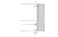
また、図6の断面において、スキャロップの出っ張り部の先端からスキャロップの掘りこみ部までの距離をスキャロップの掘り込み深さDとする。また、図6の断面において、スキャロップの出っ張り部の先端から溝形状の掘り込み部までの距離を溝形状の掘り込み深さXとする。このように定義した場合、スキャロップの影響を無くす形状とするためには、XがDより大きいことが好ましい。 In addition, in the cross section of FIG. 6, the distance from the tip of the scallop protruding portion to the scallop digging portion is defined as the scallop digging depth D. In the cross section of FIG. 6, the distance from the tip of the scallop protruding portion to the groove-shaped digging portion is defined as the groove-shaped digging depth X. When defined in this way, it is preferable that X is greater than D in order to obtain a shape that eliminates the influence of scallops.
また、液空気の置換をより効率良く行うためには、インク供給口の壁面に、流し込む液に対応して、親水性又は親油性を付与する前処理を行うことも有用である。また、超音波により基板全体を振動させ、液をより流し込みやすくすることも有用である。 In order to more efficiently replace liquid air, it is also useful to perform a pretreatment that imparts hydrophilicity or lipophilicity to the wall surface of the ink supply port in accordance with the liquid to be poured. It is also useful to vibrate the entire substrate with ultrasonic waves so that the liquid can be poured more easily.
以下に、本発明の液体吐出ヘッドの実施形態について図面を参照して詳細に説明する。また、以下の説明では、本発明の適用例として、インクジェット記録ヘッドを例に挙げて説明することもあるが、本発明の適用範囲はこれに限定されるものではない。例えば、インク記録以外にも、バイオッチップ作製や電子回路印刷に用いることができ、本発明は液体を吐出する液体吐出ヘッドに関するものである。液体吐出ヘッドとしては、インクジェット記録ヘッドの他にも、例えばカラーフィルター製造用ヘッド等も挙げられる。 Hereinafter, embodiments of a liquid discharge head according to the present invention will be described in detail with reference to the drawings. In the following description, as an application example of the present invention, an inkjet recording head will be described as an example, but the scope of application of the present invention is not limited to this. For example, in addition to ink recording, the present invention can be used for biochip fabrication and electronic circuit printing, and the present invention relates to a liquid ejection head that ejects liquid. As the liquid discharge head, in addition to the ink jet recording head, for example, a head for producing a color filter can be cited.
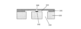
図8は、本実施形態のインクジェット記録ヘッドの構成例を示す断面概略図である。 FIG. 8 is a schematic cross-sectional view illustrating a configuration example of the ink jet recording head of the present embodiment.
図8に示すように、インクジェット記録ヘッドは、流路形成部材105が上面に形成された基板100を有する。基板1の流路形成部材105が配置される面と反対側の面(裏面)には、支持部材(不図示)を配置することができる。流路形成部材105はインク流路(液体流路)113とインク吐出口(吐出口)106を構成する。基板100は、インク(液体)を吐出するための電気熱変換素子等の吐出エネルギー発生素子102を複数有し、また該吐出エネルギー発生素子を駆動させるための配線等(不図示)を含むことができる。また、基板100はインク流路113にインクを供給するためのインク供給口(液体供給口)110を有する。インク供給口110は基板100を貫通して複数形成されている。
As shown in FIG. 8, the ink jet recording head includes a
本発明において、液体供給口は、エネルギー発生素子が形成されている表面側と反対側の面である裏面から表面側に向かって伸びる溝形状が少なくとも1つ壁面に形成されている。つまり、液体供給口の壁面には溝形状が開口面から基板表面側に向かって形成されている。また、供給口は基板の面方向に垂直に形成され、溝形状も面方向に対して略垂直方向に形成されていることが好ましい。 In the present invention, the liquid supply port has at least one groove formed on the wall surface extending from the back surface, which is the surface opposite to the surface side where the energy generating element is formed, toward the surface side. That is, a groove shape is formed on the wall surface of the liquid supply port from the opening surface toward the substrate surface side. The supply port is preferably formed perpendicular to the surface direction of the substrate, and the groove shape is also formed substantially perpendicular to the surface direction.
本発明の液体吐出ヘッドは、液体供給口の壁面に溝形状を有するため、ストップ層の除去液等が良好に流れ込むことができ、製造時にストップ膜の除去を歩留まり良く効率的に除去することができる。また、液体供給口に溝形状を有するため、インク等の液体を安定して液体供給口に供給することが可能となり、泡残り等の発生が抑制された信頼性の高い液体吐出ヘッドを得ることができる。 Since the liquid discharge head of the present invention has a groove shape on the wall surface of the liquid supply port, the removal liquid of the stop layer and the like can flow in well, and the removal of the stop film can be efficiently removed with good yield during manufacturing. it can. In addition, since the liquid supply port has a groove shape, it is possible to stably supply liquid such as ink to the liquid supply port, and to obtain a highly reliable liquid discharge head in which the occurrence of bubble residue and the like is suppressed. Can do.
溝形状としては、残渣をマスクとして形成される溝状のものの集合体から成るものや、エッチング開始面上方から掘り込まれたようにギザ形状と成っているもの、もしくはその組み合わせから成る。溝形状に大小様々な幅の物を形成することで、メニスカスを張ることなく幅の広い溝より液が流れ込むため適している。またメニスカスが崩れるためにはある程度の深さまで液が流れ込む必要があるため、溝形状の深さは開口終端部に向かってある程度の深さ以上で形成することが望ましい。その深さとしては、液体供給口の開口表面から30μm以上であることが好ましい。溝形状の形成方法としては、上述した通りで、耐エッチングマスクの残渣を利用して、インク供給口の壁面に溝形状を形成する。 The groove shape is composed of a collection of groove-shaped objects formed using a residue as a mask, a groove shape formed by digging from above the etching start surface, or a combination thereof. By forming the groove shape with various widths, it is suitable because the liquid flows from the wide groove without stretching the meniscus. Further, since the liquid needs to flow to a certain depth in order for the meniscus to collapse, it is desirable that the depth of the groove shape be greater than a certain depth toward the terminal end of the opening. The depth is preferably 30 μm or more from the opening surface of the liquid supply port. As a method for forming the groove shape, as described above, the groove shape is formed on the wall surface of the ink supply port using the residue of the etching resistant mask.
基板は例えばシリコン基板を用いて構成することができる。 The substrate can be configured using, for example, a silicon substrate.
液体供給口は、例えば異方性エッチングにより形成することができる。異方性エッチングとしては、RIE(リアクティブイオンエッチング)等のドライエッチングを好適に挙げることができる。また、RIEを用いたボッシュプロセスにより形成することが好ましい。 The liquid supply port can be formed by, for example, anisotropic etching. A preferable example of anisotropic etching is dry etching such as RIE (reactive ion etching). Moreover, it is preferable to form by the Bosch process using RIE.
流路形成部材の材料としては、例えば、感光性エポキシ樹脂、感光性アクリル樹脂などを用いることができ、光反応によるカチオン重合性化合物を用いることが好ましい。また、流路形成部材の材料としては、用いる液体の種類および特性によって耐久性などが大きく左右されるので、用いるインク等の液体によっては適当な化合物を選択することができる。 As a material of the flow path forming member, for example, a photosensitive epoxy resin, a photosensitive acrylic resin, or the like can be used, and it is preferable to use a cationically polymerizable compound by a photoreaction. Further, as the material of the flow path forming member, durability and the like are greatly influenced by the type and characteristics of the liquid used, and therefore an appropriate compound can be selected depending on the liquid such as the ink used.
基板には電気信号を伝送するための配線層を有することができ、例えばAl配線を成膜技術を用いて形成することができる。 The substrate can have a wiring layer for transmitting an electric signal. For example, an Al wiring can be formed by using a film forming technique.
また、本実施形態としてのインクジェット記録ヘッドは、プリンタ、複写機、通信システムを有するファクシミリ、プリンタ部を有するワードプロセッサなどの装置、更には各種処理装置と複合的に組み合わせた産業記録装置に搭載可能である。そして、このインクジェット記録ヘッドを用いることによって、紙、糸、繊維、布帛、皮革、金属、プラスチック、ガラス、木材、セラミックスなど種々の記録媒体に記録を行うことができる。 In addition, the ink jet recording head according to the present embodiment can be mounted on an apparatus such as a printer, a copying machine, a facsimile having a communication system, a word processor having a printer unit, or an industrial recording apparatus combined with various processing apparatuses. is there. By using this ink jet recording head, recording can be performed on various recording media such as paper, thread, fiber, fabric, leather, metal, plastic, glass, wood, and ceramics.
(実施例1)
本実施例においては、図1(a)〜(e)で示すインクジェットヘッドの製造方法によって、インクジェット記録ヘッドを製造した。
Example 1
In this example, an ink jet recording head was manufactured by the method of manufacturing an ink jet head shown in FIGS.
まず、基板1として、インクを吐出させるためのエネルギー発生素子とドライバーやロジック回路が形成されたシリコン基板を準備した。この基板にストップ層3となるAL膜を形成した。
First, a silicon substrate on which an energy generating element for discharging ink, a driver, and a logic circuit were formed was prepared as the
次に、基板1の表面にインク流路の型となる流路型部材3を注型法を用いて形成した。
Next, a flow
次に、基板1の裏面に耐エッチング膜8となる感光性樹脂をスピンコートにより形成した。感光性樹脂としてAZ−P4620(AZエレクトロニックマテリアルズ社製、商品名)を用いた。
Next, a photosensitive resin to be the etching
次に、感光性樹脂に対してイーヴィーグループ社製の露光機を用いて1000mJ/cm2の露光量でインク供給口パターンのフォトマスクAを通して露光処理を行った。 Next, the photosensitive resin was exposed through a photomask A having an ink supply port pattern with an exposure amount of 1000 mJ / cm 2 using an exposure machine manufactured by Evey Group.
次に、AZ−400Kリムーバーを用いて現像を行い、インク供給口の開口パターンが形成された耐エッチングマスク8'を形成した。
Next, development was performed using an AZ-400K remover to form an etching
次に、耐エッチングマスク8'を100℃1時間、オーブンにて加熱した。
Next, the etching
次に、耐エッチングマスク8'上よりAMS200(ALCATEL社製、商品名)を用いてボッシュプロセスにて基板1をAL膜からなるストップ層3までドライエッチング処理を行い、インク供給口10を形成した。
Next, the
上記の方法で作製したインクジェット記録ヘッドは、インク供給口の側壁に深さ方向(面方向に垂直な方向)に開口表面から溝形状が複数形成されていた(図7参照)。また、溝形状の少なくとも1つは30μm以上の長さであった。 In the ink jet recording head produced by the above method, a plurality of groove shapes were formed from the opening surface in the depth direction (direction perpendicular to the surface direction) on the side wall of the ink supply port (see FIG. 7). Further, at least one of the groove shapes had a length of 30 μm or more.
このインク供給口から除去液を用いてAL膜からなるストップ層を除去すると、短時間で歩留まり良く除去することができた。 When the stop layer made of the AL film was removed from the ink supply port using the removing liquid, it was possible to remove it with a high yield in a short time.
(実施例2)
本実施例では、耐エッチング膜にインク供給口の開口パターンを形成するための露光処理の際に、マスクをフォーカス位置より30μm上げた状態にて露光を行った。また、開口パターン形成後の加熱処理は行わなかった。それら以外は実施例1と同様の工程においてインクジェット記録ヘッドを作製した。
(Example 2)
In this example, the exposure was performed in a state where the mask was raised by 30 μm from the focus position during the exposure process for forming the opening pattern of the ink supply port in the etching resistant film. Further, no heat treatment was performed after the opening pattern was formed. Other than those, an ink jet recording head was prepared in the same process as in Example 1.
本実施例で形成したインク供給口の壁面には開口表面から面方向に垂直な方向に向けて溝形状が複数形成されていた。溝形状は長いもので30μm以上であった。 In the wall surface of the ink supply port formed in the present embodiment, a plurality of groove shapes were formed from the opening surface toward the direction perpendicular to the surface direction. The groove shape was long and 30 μm or more.
このインク供給口から除去液を用いてAL膜からなるストップ層を除去すると、短時間で歩留まり良く除去することができた。 When the stop layer made of the AL film was removed from the ink supply port using the removing liquid, it was possible to remove it with a high yield in a short time.
(比較例1)
耐エッチング膜に微細なインク供給口パターンを形成した後に、100℃1時間オーブンにて加熱を行うことなく、耐エッチング膜に微細なインク供給口パターンを形成した以外は、実施例1と同様の工程においてインクジェット記録ヘッドを作製した。
(Comparative Example 1)
After forming a fine ink supply port pattern on the etching resistant film, the same as in Example 1 except that the fine ink supply port pattern was formed on the etching resistant film without heating in an oven at 100 ° C. for 1 hour. An ink jet recording head was produced in the process.
このインク供給口では開口開始部から開口終端部にかけてスキャロップが繰り返される形状となった。 The ink supply port has a shape in which scalloping is repeated from the opening start portion to the opening end portion.
インク供給口から除去液を用いてAL膜からなるストップ層を除去することを試みたが、除去液が開口終端部まで到達していないインク供給口が数箇所発生し、ストップ層の除去が不十分となった。 Attempts were made to remove the stop layer made of the AL film from the ink supply port using the removal liquid, but there were several ink supply ports where the removal liquid did not reach the end of the opening, and removal of the stop layer was not possible. It was enough.
1 基板
2 エネルギー発生素子
3 ストップ層
4 流路型部材
5 流路形成部材
6 吐出口
7 保護膜
8 耐エッチング膜
8' 耐エッチングマスク
9 開口(開口パターン)
10 液体供給口(インク供給口)
11 溝形状
12 液(除去液)
DESCRIPTION OF
10 Liquid supply port (ink supply port)
11
Claims (19)
前記基板には、前記吐出口と連通し、前記吐出口に液体を供給するための液体供給部が設けられており、
前記液体供給部は、前記基板の、前記エネルギー発生素子が形成されている側の面である第1の面から前記第1の面の反対側の面である第2の面まで貫通しており、
前記液体供給部の壁面には、前記液体供給部が前記基板を貫通する方向に沿って伸びる溝形状が少なくとも1つあることを特徴とする液体吐出ヘッド。 A liquid discharge head including a substrate having an energy generating element that generates energy for discharging liquid from a discharge port,
The substrate is provided with a liquid supply unit that communicates with the discharge port and supplies a liquid to the discharge port.
The liquid supply part penetrates from the first surface, which is the surface on the side where the energy generating element is formed, of the substrate to the second surface, which is the surface opposite to the first surface. ,
The liquid discharge head according to claim 1, wherein the wall surface of the liquid supply unit has at least one groove shape extending along a direction in which the liquid supply unit penetrates the substrate.
(1)前記エネルギー発生素子を第1の面側に有する基板の、前記第1の面の反対側の面である第2の面に、前記液体供給部に対応する開口を有する耐エッチングマスクを形成する工程と、
(2)前記耐エッチングマスクを用いて前記基板をドライエッチング処理することにより、前記第2の面から第1の面まで貫通する前記液体供給部を形成する工程と、を含み、
前記工程(1)において、前記耐エッチングマスクの前記開口の周辺領域は前記開口に近いほど薄くなっている部分を有することを特徴とする液体吐出ヘッドの製造方法。 A substrate including a liquid supply unit for supplying the liquid to a liquid flow path communicating with a discharge port for discharging the liquid, and an energy generating element for generating energy for discharging the liquid from the discharge port. In the manufacturing method of the liquid discharge head,
(1) An etching resistant mask having an opening corresponding to the liquid supply portion on a second surface, which is a surface opposite to the first surface, of the substrate having the energy generating element on the first surface side. Forming, and
(2) forming the liquid supply portion penetrating from the second surface to the first surface by dry-etching the substrate using the etching-resistant mask,
In the step (1), the peripheral region of the opening of the etching-resistant mask has a portion that is thinner as it is closer to the opening.
A stop layer is provided on the first surface side of the substrate, and after the dry etching process is performed until reaching the stop layer, the stop layer is removed by pouring a removing liquid from the liquid supply unit. The method for manufacturing a liquid discharge head according to claim 12 .
Priority Applications (1)
| Application Number | Priority Date | Filing Date | Title |
|---|---|---|---|
| JP2011161866A JP5967876B2 (en) | 2010-09-21 | 2011-07-25 | Liquid discharge head and manufacturing method thereof |
Applications Claiming Priority (3)
| Application Number | Priority Date | Filing Date | Title |
|---|---|---|---|
| JP2010211139 | 2010-09-21 | ||
| JP2010211139 | 2010-09-21 | ||
| JP2011161866A JP5967876B2 (en) | 2010-09-21 | 2011-07-25 | Liquid discharge head and manufacturing method thereof |
Publications (3)
| Publication Number | Publication Date |
|---|---|
| JP2012086553A JP2012086553A (en) | 2012-05-10 |
| JP2012086553A5 JP2012086553A5 (en) | 2014-08-28 |
| JP5967876B2 true JP5967876B2 (en) | 2016-08-10 |
Family
ID=45817374
Family Applications (1)
| Application Number | Title | Priority Date | Filing Date |
|---|---|---|---|
| JP2011161866A Active JP5967876B2 (en) | 2010-09-21 | 2011-07-25 | Liquid discharge head and manufacturing method thereof |
Country Status (2)
| Country | Link |
|---|---|
| US (1) | US8419168B2 (en) |
| JP (1) | JP5967876B2 (en) |
Families Citing this family (6)
| Publication number | Priority date | Publication date | Assignee | Title |
|---|---|---|---|---|
| JP5800534B2 (en) * | 2011-03-09 | 2015-10-28 | キヤノン株式会社 | Manufacturing method of substrate for liquid discharge head |
| JP6157184B2 (en) * | 2012-04-10 | 2017-07-05 | キヤノン株式会社 | Method for manufacturing liquid discharge head |
| JP6223033B2 (en) * | 2013-07-17 | 2017-11-01 | キヤノン株式会社 | Substrate processing method |
| JP6604740B2 (en) * | 2014-05-30 | 2019-11-13 | キヤノン株式会社 | Method for manufacturing semiconductor substrate and substrate for liquid discharge head |
| TW201714757A (en) * | 2015-10-19 | 2017-05-01 | 精工愛普生股份有限公司 | Electronic device, liquid ejecting head, liquid ejecting apparatus, and method of manufacturing electronic device |
| JP2018094845A (en) | 2016-12-15 | 2018-06-21 | キヤノン株式会社 | Liquid discharge head |
Family Cites Families (6)
| Publication number | Priority date | Publication date | Assignee | Title |
|---|---|---|---|---|
| US6555480B2 (en) | 2001-07-31 | 2003-04-29 | Hewlett-Packard Development Company, L.P. | Substrate with fluidic channel and method of manufacturing |
| JP2004209741A (en) * | 2002-12-27 | 2004-07-29 | Canon Inc | Inkjet recording head |
| EP1768848B1 (en) | 2004-06-28 | 2010-07-21 | Canon Kabushiki Kaisha | Liquid discharge head manufacturing method, and liquid discharge head obtained using this method |
| JP2006130868A (en) | 2004-11-09 | 2006-05-25 | Canon Inc | Inkjet recording head and its manufacturing method |
| JP4981491B2 (en) | 2007-03-15 | 2012-07-18 | キヤノン株式会社 | Ink jet head manufacturing method and through electrode manufacturing method |
| JP2009226660A (en) * | 2008-03-21 | 2009-10-08 | Fujifilm Corp | Method for patterning by dry etching, mold used for it and method for manufacturing inkjet head |
-
2011
- 2011-07-25 JP JP2011161866A patent/JP5967876B2/en active Active
- 2011-08-26 US US13/218,851 patent/US8419168B2/en active Active
Also Published As
| Publication number | Publication date |
|---|---|
| JP2012086553A (en) | 2012-05-10 |
| US20120069094A1 (en) | 2012-03-22 |
| US8419168B2 (en) | 2013-04-16 |
Similar Documents
| Publication | Publication Date | Title |
|---|---|---|
| JP5967876B2 (en) | Liquid discharge head and manufacturing method thereof | |
| JP2010137460A (en) | Method for manufacturing inkjet recording head | |
| JP5460760B2 (en) | Method for manufacturing liquid discharge head | |
| JP2006027273A (en) | Method of manufacturing inkjet head | |
| CN1926056B (en) | Slotted forming methods and fluid ejecting device | |
| US8647896B2 (en) | Process for producing a substrate for a liquid ejection head | |
| US9676193B2 (en) | Substrate processing method and method of manufacturing substrate for liquid discharge head including forming hole in substrate by dry etching | |
| US20160176192A1 (en) | Method for machining silicon substrate, and liquid ejection head | |
| US7575303B2 (en) | Liquid-ejection head and method for producing the same | |
| JP5701014B2 (en) | Method for manufacturing ejection element substrate | |
| JP2010142972A (en) | Method for manufacturing inkjet recording head | |
| WO2008075715A1 (en) | Method of producing nozzle plate for liquid discharge head, nozzle plate for liquid discharge head, and liquid discharge head | |
| KR100701131B1 (en) | Manufacturing method of ink jet recording head and ink jet recording head manufactured by manufacturing method | |
| JP5932342B2 (en) | Method for manufacturing liquid discharge head | |
| JP2007136875A (en) | Substrate for inkjet recording head | |
| KR100942871B1 (en) | Ink jet print head manufacturing method and ink jet print head | |
| US8070265B2 (en) | Heater stack in a micro-fluid ejection device and method for forming floating electrical heater element in the heater stack | |
| KR20070082788A (en) | The method for producing inkjet head | |
| US9205654B2 (en) | Method of manufacturing a liquid ejection head | |
| JP2009119773A (en) | Nozzle plate for liquid discharging head and method for manufacturing the same | |
| JP2014076571A (en) | Method for manufacturing liquid discharge head | |
| JP2009226845A (en) | Production method of inkjet recording head and production method of microstructure | |
| JP2006082331A (en) | Process for manufacturing ink jet recording head | |
| JP2007210242A (en) | Inkjet recording head and its manufacturing method | |
| JP2014083824A (en) | Method for manufacturing liquid discharge head |
Legal Events
| Date | Code | Title | Description |
|---|---|---|---|
| RD04 | Notification of resignation of power of attorney |
Free format text: JAPANESE INTERMEDIATE CODE: A7424 Effective date: 20140430 |
|
| A521 | Written amendment |
Free format text: JAPANESE INTERMEDIATE CODE: A523 Effective date: 20140711 |
|
| A621 | Written request for application examination |
Free format text: JAPANESE INTERMEDIATE CODE: A621 Effective date: 20140711 |
|
| A977 | Report on retrieval |
Free format text: JAPANESE INTERMEDIATE CODE: A971007 Effective date: 20150414 |
|
| A131 | Notification of reasons for refusal |
Free format text: JAPANESE INTERMEDIATE CODE: A131 Effective date: 20150421 |
|
| A521 | Written amendment |
Free format text: JAPANESE INTERMEDIATE CODE: A523 Effective date: 20150619 |
|
| A131 | Notification of reasons for refusal |
Free format text: JAPANESE INTERMEDIATE CODE: A131 Effective date: 20151124 |
|
| A521 | Written amendment |
Free format text: JAPANESE INTERMEDIATE CODE: A523 Effective date: 20160119 |
|
| TRDD | Decision of grant or rejection written | ||
| A01 | Written decision to grant a patent or to grant a registration (utility model) |
Free format text: JAPANESE INTERMEDIATE CODE: A01 Effective date: 20160607 |
|
| A61 | First payment of annual fees (during grant procedure) |
Free format text: JAPANESE INTERMEDIATE CODE: A61 Effective date: 20160705 |
|
| R151 | Written notification of patent or utility model registration |
Ref document number: 5967876 Country of ref document: JP Free format text: JAPANESE INTERMEDIATE CODE: R151 |