JP5967660B2 - Slot machine - Google Patents
Slot machine Download PDFInfo
- Publication number
- JP5967660B2 JP5967660B2 JP2013136065A JP2013136065A JP5967660B2 JP 5967660 B2 JP5967660 B2 JP 5967660B2 JP 2013136065 A JP2013136065 A JP 2013136065A JP 2013136065 A JP2013136065 A JP 2013136065A JP 5967660 B2 JP5967660 B2 JP 5967660B2
- Authority
- JP
- Japan
- Prior art keywords
- command
- game
- switch
- control means
- state
- Prior art date
- Legal status (The legal status is an assumption and is not a legal conclusion. Google has not performed a legal analysis and makes no representation as to the accuracy of the status listed.)
- Active
Links
Images


Description
本発明は、遊技の進行を制御するメイン制御手段と、演出の出力を制御するサブ制御手段とを備え、メイン制御手段からサブ制御手段にコマンドを送信するスロットマシンに関するものである。 The present invention relates to a slot machine that includes a main control unit that controls the progress of a game and a sub-control unit that controls the output of an effect, and transmits a command from the main control unit to the sub-control unit .
従来のスロットマシンにおいて、遊技の進行を制御するメイン制御手段と、演出の出力を制御するサブ制御手段とを備え、メイン制御手段は、サブ制御手段にコマンドを送信し、サブ制御手段は、受信したコマンドに応じて演出の出力を制御するスロットマシンが知られている(特許文献1参照)。 In a conventional slot machine, a main control means for controlling the progress of the game and a sub-control means for controlling the output of the effect are provided, the main control means transmits a command to the sub-control means, and the sub-control means receives There is known a slot machine that controls the output of an effect in response to a command (see Patent Document 1).
本発明が解決しようとする課題は、コマンド送信用のバッファ領域に使用するメモリの容量を増加させなくても、生成したコマンドがコマンド送信用のバッファ領域から溢れないようにすることである。 The problem to be solved by the present invention is to prevent a generated command from overflowing the command transmission buffer area without increasing the capacity of the memory used for the command transmission buffer area .
本発明は、以下の解決手段によって、上述の課題を解決する。なお、かっこ書きにて、対応する実施形態を示す。
請求項1の発明は、
遊技の進行を制御するメイン制御手段(50)と、
演出の出力を制御するサブ制御手段(80)と
を備え、
前記メイン制御手段は、
エラーが発生したか否かを判定する手段(メイン側エラー検知手段71)と、
コマンドを生成するコマンド生成手段(73)と、
生成したコマンドを記憶するバッファ領域(74)と、
前記バッファ領域に記憶されているコマンドを前記サブ制御手段に送信するコマンド送信手段(75)と
を備え、
前記メイン制御手段は、
遊技の進行のためのメイン処理を遊技者の操作に応じて繰り返し実行可能であるとともに、所定時間(2.235ms)ごとに割込み処理を実行し、
前記メイン処理では、前記メイン制御手段から前記サブ制御手段に送信する複数個のコマンドを前記コマンド生成手段が生成するコマンド集中区間を有するとともに、前記コマンド集中区間の途中又は経過後に、前記コマンド生成手段がコマンドを生成することなく前記バッファ領域に記憶されているコマンドを前記コマンド送信手段が送信するための待ち時間を有し、
前記割込み処理では、前記待ち時間中であるか否かにかかわらず、所定のエラーが発生したと判定したことに基づいて、前記コマンド生成手段が所定のコマンドを生成する場合を有する
ことを特徴とする。
The present invention solves the above-described problems by the following means. Note that the corresponding embodiment is shown in parentheses.
The invention of claim 1
Main control means (50) for controlling the progress of the game;
And a sub-control means (80) for controlling the output of the effect,
The main control means includes
Means for determining whether an error has occurred (main-side error detection means 71);
Command generation means (73) for generating a command;
A buffer area (74) for storing the generated command ;
Command sending means (75) for sending the command stored in the buffer area to the sub-control means,
The main control means includes
The main process for the progress of the game can be repeatedly executed according to the player's operation, and the interrupt process is executed every predetermined time (2.235 ms)
In the main process, the command generation unit generates a plurality of commands to be transmitted from the main control unit to the sub-control unit, and the command generation unit includes the command generation unit during or after the command concentration period. Has a waiting time for the command transmission means to transmit the command stored in the buffer area without generating a command,
The interrupt processing includes a case where the command generation unit generates a predetermined command based on the determination that a predetermined error has occurred regardless of whether or not the waiting time is in progress. To do.
本発明によれば、コマンド集中区間の途中又は経過後に待ち時間を設け、この待ち時間の間は、コマンドを生成することなく、バッファ領域に記憶されているコマンドを送信するので、バッファ領域に使用するメモリの容量を増加させなくても、生成したコマンドがバッファ領域から溢れないようにすることができる。 According to the present invention, a waiting time is provided during or after the command concentration section, and during this waiting time, a command stored in the buffer area is transmitted without generating a command. The generated command can be prevented from overflowing from the buffer area without increasing the memory capacity .
(第1実施形態)
以下、図面等を参照して、本発明の一実施形態について説明する。
なお、以下の実施形態のスロットマシン10は、メダルを遊技媒体としているが、メダルに限らず、遊技球等であってもよいのはもちろんである。
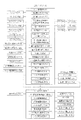
図1は、本実施形態におけるスロットマシン10の制御の概略を示すブロック図である。スロットマシン10は、メイン制御手段50とサブ制御手段80とを備える。
(First embodiment)
Hereinafter, an embodiment of the present invention will be described with reference to the drawings.
In the slot machine 10 of the following embodiment, medals are used as game media. However, the present invention is not limited to medals and may be game balls or the like.
FIG. 1 is a block diagram showing an outline of control of the slot machine 10 in the present embodiment. The slot machine 10 includes a main control unit 50 and a sub control unit 80.
メイン制御手段50は、役の抽選、リール31の駆動(回転及び停止)制御、及び入賞時の払出し等の遊技の進行を制御するものである。メイン制御手段50は、メイン制御基板(図示せず)上に設けられており、演算等を行うCPU、遊技の進行等に必要なプログラム等を記憶しておくROM、CPUが各種の制御を行うときに取り込んだデータ等を一時的に記憶しておくRAM等を備える。 The main control means 50 controls the progress of games such as winning lottery, reel 31 drive (rotation and stop) control, and payout when winning. The main control means 50 is provided on a main control board (not shown), and a CPU for performing calculations, a ROM for storing programs necessary for the progress of games, etc., and the CPU perform various controls. A RAM or the like is provided for temporarily storing data that is sometimes captured.
また、サブ制御手段80は、遊技中及び遊技待機中における演出の選択・出力等を制御するものである。サブ制御手段80は、サブ制御基板(図示せず)上に設けられており、演算等を行うCPU、演出用のデータ等(演出パターン等)を記憶しておくROM、CPUが各種の演出を出力するときに取り込んだデータ等を一時的に記憶しておくRAM等を備える。 The sub-control means 80 controls the selection / output of effects during the game and during the game standby. The sub-control means 80 is provided on a sub-control board (not shown). The CPU that performs calculations, the ROM that stores data for effects (such as effect patterns), and the CPU perform various effects. A RAM or the like for temporarily storing data taken in when outputting is provided.
なお、サブ制御基板は、メイン制御基板の下位に属する制御基板である。そして、メイン制御手段50とサブ制御手段80とは電気的に接続されており、メイン制御手段50からサブ制御手段80に一方向で、演出の出力に必要な信号や情報(コマンド)を送信するように形成されている。 The sub control board is a control board belonging to a lower level of the main control board. The main control means 50 and the sub control means 80 are electrically connected, and transmit signals and information (commands) necessary for production output in one direction from the main control means 50 to the sub control means 80. It is formed as follows.
図1に示すように、メイン制御手段50の入力側(図1中、左側)には、遊技者が遊技を進行する上で操作する操作スイッチであるベットスイッチ40、スタートスイッチ41、及び3つ(左、中、右)のストップスイッチ42が電気的に接続されている。
また、メイン制御手段50の入力側には、メダルセレクタ43a、第1投入検知センサ43b、第2投入検知センサ43c、払出し検知センサ44、設定キースイッチ45、設定変更スイッチ46、リセットスイッチ47、ドア開閉検知センサ48、及びカバー開閉検知センサ49が電気的に接続されている。
As shown in FIG. 1, on the input side (left side in FIG. 1) of the main control means 50, a bet switch 40, a start switch 41, and three operation switches that are operated by the player to advance the game. (Left, middle, right) stop switches 42 are electrically connected.
Further, on the input side of the main control means 50, a medal selector 43a, a first insertion detection sensor 43b, a second insertion detection sensor 43c, a payout detection sensor 44, a setting key switch 45, a setting change switch 46, a reset switch 47, a door An open / close detection sensor 48 and a cover open / close detection sensor 49 are electrically connected.
ベットスイッチ40は、遊技者が貯留メダルを当該遊技のために投入するときに操作するスイッチである。本実施形態では、いずれの遊技状態においても、3枚のメダルを投入して遊技を行うように設定されている。このため、ベットスイッチ40を操作すると、3枚分の貯留メダルを電気的に投入するとともに、貯留メダルの枚数(クレジット数)から「3」を減算する処理が行われる。なお、これに限らず、メダルの投入枚数は、1枚又は2枚でもよい。そして、1枚ベット用や2枚ベット用のベットスイッチを設けてもよい。 The bet switch 40 is a switch operated when the player inserts a stored medal for the game. In this embodiment, in any gaming state, it is set to play a game by inserting three medals. Therefore, when the bet switch 40 is operated, three stored medals are electrically inserted, and a process of subtracting “3” from the number of stored medals (number of credits) is performed. The number of medals inserted is not limited to this, and may be one or two. A bet switch for one bet or two bets may be provided.
メダル投入口43は、実際のメダルを遊技者が投入する部分であり、フロントマスク部(前面扉)の前面側(遊技者側)に設けられている。
また、フロントマスク部の後面側(裏面側)には、メダル投入口43から投入されたメダルを選別するメダルセレクタ43aが設けられている。
メダル投入口43から投入されたメダルは、メダルセレクタ43aに到達する。また、メダルセレクタ43aでは、投入されたメダルが正規のものか否か、及びメダルの投入操作が有効の状態か否かに応じて、メダルの進路を切り替える。
The
A medal selector 43 a for selecting medals inserted from the
The medal inserted from the
具体的には、メダルセレクタ43aは、メダルの投入操作が有効の状態であり、かつ投入されたメダルが正規のものであれば、そのメダルをホッパー33aに誘導する。
これに対し、メダルセレクタ43aは、メダルの投入操作が無効の状態であれば、投入されたメダルが正規のものであるか否かにかかわらず、そのメダルを遊技者に返却するために、メダル受け皿に誘導する。
また、メダルセレクタ43aは、投入されたメダルが正規のものでなければ、メダルの投入操作が有効の状態か否かにかかわらず、そのメダルを遊技者に返却するために、メダル受け皿に誘導する。
Specifically, the medal selector 43a guides the medal to the hopper 33a if the medal insertion operation is valid and the inserted medal is a regular one.
On the other hand, if the medal insertion operation is invalid, the medal selector 43a returns the medal to the player regardless of whether the inserted medal is genuine or not. Guide to the saucer.
Further, if the inserted medal is not genuine, the medal selector 43a guides the medal to the medal tray in order to return the medal to the player regardless of whether or not the medal inserting operation is in a valid state. .
さらに、メダルセレクタ43aを通過してホッパー33aへ向かうメダルの通路の途中には、上流側から順に、第1投入検知センサ43b及び第2投入検知センサ43cが設けられている。
第1投入検知センサ43b及び第2投入検知センサ43cは、いずれも、発光素子と受光素子とを有し、発光素子から発せられた光を受光素子で検知している。そして、通路を通るメダルは、発光素子と受光素子との間を通過する。このとき、受光素子に入射する光が一瞬遮られ、これによりメダルの通過を検知する。
Furthermore, a first insertion detection sensor 43b and a second insertion detection sensor 43c are provided in order from the upstream side in the middle of a medal path that passes through the medal selector 43a toward the hopper 33a.
Each of the first input detection sensor 43b and the second input detection sensor 43c has a light emitting element and a light receiving element, and detects light emitted from the light emitting element by the light receiving element. The medal passing through the passage passes between the light emitting element and the light receiving element. At this time, light incident on the light receiving element is blocked for a moment, thereby detecting the passage of the medal.
そして、第1投入検知センサ43b、第2投入検知センサ43cの順にメダルの通過を検知すると、メダルが投入されたと判断する。
これに対し、第2投入検知センサ43c、第1投入検知センサ43bの順にメダルの通過を検知すると、エラー(メダルの逆流)が発生したと判断する。
また、第1投入検知センサ43b及び/又は第2投入検知センサ43cの遮光が一定時間以上継続すると、エラー(メダル詰まり)が発生したと判断する。
When the passage of medals is detected in the order of the first insertion detection sensor 43b and the second insertion detection sensor 43c, it is determined that a medal has been inserted.
On the other hand, when the passage of medals is detected in the order of the second insertion detection sensor 43c and the first insertion detection sensor 43b, it is determined that an error (a reverse flow of medals) has occurred.
Further, if the light blocking of the first insertion detection sensor 43b and / or the second insertion detection sensor 43c continues for a certain time or more, it is determined that an error (medal clogging) has occurred.
そして、メダル投入口43からメダルを投入することは、ベットスイッチ40を操作することと同様の役割を果たす。
また、本明細書において、「メダルの投入」とは、メダル投入口43に実際のメダルを投入すること、及びベットスイッチ40を操作することの双方を含む意味で使用する。
Then, inserting a medal from the
Further, in this specification, “inserting a medal” is used to include both putting an actual medal into the
さらにまた、スタートスイッチ41は、(左、中、右のすべての)リール31を始動させるときに遊技者が操作するスイッチである。
さらに、(左、中、右)ストップスイッチ42は、3つ(左、中、右)のリール31に対応して3つ設けられ、対応するリール31を停止させるときに遊技者が操作するスイッチである。
Furthermore, the start switch 41 is a switch operated by the player when starting the reels 31 (all of left, middle, and right).
Further, three (left, middle, right) stop switches 42 are provided corresponding to the three (left, middle, right) reels 31, and are switches that the player operates when stopping the corresponding reels 31. It is.
電源ユニットは、スロットマシン10の筐体内部に設けられており、メイン制御基板やサブ制御基板等に電力を供給する電源基板と、電源基板を収納する電源ボックスとを備えている。
また、電源ボックスの前面には、電源のオン/オフを切り替えるための電源スイッチと、設定キーが挿入される設定キー挿入口とが設けられているとともに、これらを覆う開閉自在のスイッチカバーが設けられている。
The power supply unit is provided inside the housing of the slot machine 10 and includes a power supply board that supplies power to a main control board, a sub control board, and the like, and a power supply box that houses the power supply board.
The front of the power supply box is provided with a power switch for switching on / off of the power supply and a setting key insertion slot into which a setting key is inserted, and an openable / closable switch cover for covering these. It has been.
スイッチカバーを開けると、電源スイッチの操作が可能になるとともに、設定キー挿入口への設定キーの挿入が可能になる。
また、設定キー挿入口に設定キーを挿入して、設定キーを時計周りに90度回転させると、設定キースイッチ45がオンになり、この状態から設定キーを反時計周りに90度回転させると、設定キースイッチ45がオフになる。
When the switch cover is opened, the power switch can be operated and the setting key can be inserted into the setting key insertion slot.
Further, when the setting key is inserted into the setting key insertion slot and the setting key is rotated 90 degrees clockwise, the setting key switch 45 is turned on, and when the setting key is rotated 90 degrees counterclockwise from this state. The setting key switch 45 is turned off.
さらにまた、電源がオフの状態で設定キースイッチ45をオンにし、この状態で電源をオンにすると、設定値が変更可能となる設定変更モードになる。
さらに、電源がオンの状態で設定キースイッチ45をオンにすると、設定値が確認可能となる設定確認モードになる。
Furthermore, when the setting key switch 45 is turned on in a state where the power is off, and the power is turned on in this state, a setting change mode in which the setting value can be changed is entered.
Further, when the setting key switch 45 is turned on while the power is on, a setting confirmation mode is entered in which the setting value can be confirmed.
また、カバー開閉検知センサ49は、スイッチカバーの開閉を検知するセンサである。たとえば、スイッチカバーが開放された状態であるときはオンとなり、スイッチカバーが閉じた状態であるときはオフとなるように配置されている。 The cover opening / closing detection sensor 49 is a sensor that detects opening / closing of the switch cover. For example, the switch cover is arranged to be turned on when the switch cover is opened, and is turned off when the switch cover is closed.
設定変更スイッチ46は、スロットマシン10の設定値を変更・設定するときに操作するスイッチである。本実施形態では、設定値として、設定1から設定6までの6段階を設けている。そして、設定値が高くなるほど、遊技者にとって有利となるように設定している。
なお、設定変更スイッチ46は、遊技者が操作するものではなく、スロットマシン10の設置店(ホール)側で操作するものである。このため、遊技者が操作できないように、スロットマシン10の筐体内部に設定変更スイッチ46を配置している。
The setting change switch 46 is a switch operated when changing / setting the setting value of the slot machine 10. In the present embodiment, six levels from setting 1 to setting 6 are provided as setting values. The higher the set value, the more advantageous for the player.
The setting change switch 46 is not operated by the player but is operated on the store (hall) side of the slot machine 10. For this reason, the setting change switch 46 is arranged inside the housing of the slot machine 10 so that the player cannot operate it.
リセットスイッチ47は、エラーの解除等を行うときに操作するスイッチである。リセットスイッチ47も、設定変更スイッチ46と同様に、遊技者が操作するものではなく、スロットマシン10の設置店側で操作するものである。このため、遊技者が操作できないように、スロットマシン10の筐体内部にリセットスイッチ47を配置している。 The reset switch 47 is a switch that is operated when canceling an error or the like. Similarly to the setting change switch 46, the reset switch 47 is not operated by the player but operated by the store where the slot machine 10 is installed. For this reason, a reset switch 47 is arranged inside the housing of the slot machine 10 so that the player cannot operate it.
なお、リセットスイッチ47は、それ専用のスイッチを設けてもよく、また、他のスイッチと兼用にしてもよい。たとえば、1個のスイッチを、設定変更スイッチ46とリセットスイッチ47とで兼用にすることができる。この場合、1個のスイッチを、たとえば、設定変更モード中は、設定変更スイッチ46として機能させ、それ以外のときは、リセットスイッチ47として機能させることができる。 The reset switch 47 may be provided with a dedicated switch, or may be shared with other switches. For example, one switch can be shared by the setting change switch 46 and the reset switch 47. In this case, for example, one switch can function as the setting change switch 46 during the setting change mode, and can function as the reset switch 47 at other times.
ドア開閉検知センサ48は、フロントマスク部(前面扉)の開閉を検知するセンサである。たとえば、フロントマスク部が開放された状態であるときはオンとなり、フロントマスク部が閉じた状態であるときはオフとなるように配置されている。 The door opening / closing detection sensor 48 is a sensor that detects opening / closing of the front mask portion (front door). For example, it is arranged so that it is on when the front mask portion is open and off when the front mask portion is closed.
メイン制御手段50の出力側(図1中、右側)には、3つのモータ32、及びメダル払出し装置33の払出し駆動部33bが電気的に接続されている。
モータ32は、リール31を回転させるためのものであり、各リール31の回転中心部に連結され、後述するリール制御手段64によって制御される。
ここで、リール31は、左リール31、中リール31、右リール31からなり、左リール31を停止させるときに操作するストップスイッチ42が左ストップスイッチ42であり、中リール31を停止させるときに操作するストップスイッチ42が中ストップスイッチ42であり、右リール31を停止させるときに操作するストップスイッチ42が右ストップスイッチ42である。
Three motors 32 and a payout driving unit 33b of the medal payout device 33 are electrically connected to the output side (right side in FIG. 1) of the main control means 50.
The motor 32 is for rotating the reels 31, is connected to the center of rotation of each reel 31, and is controlled by a reel control means 64 described later.
Here, the reel 31 includes a left reel 31, a middle reel 31, and a right reel 31, and a stop switch 42 that is operated when the left reel 31 is stopped is the left stop switch 42, and when the middle reel 31 is stopped. The stop switch 42 to be operated is the middle stop switch 42, and the stop switch 42 to be operated when stopping the right reel 31 is the right stop switch 42.
リール31は、リング状のものであって、その外周面には複数種類の図柄(役に対応する図柄の組合せを構成している図柄)を印刷したリールテープを貼付したものである。本実施形態では、各リール31ごとに、21個の図柄表示領域(コマ)を等間隔で配置するとともに、各図柄表示領域(コマ)にそれぞれ所定の図柄を表示している。 The reel 31 is ring-shaped, and a reel tape on which a plurality of types of symbols (designs constituting a combination of symbols corresponding to the combination) is attached is attached to the outer peripheral surface thereof. In the present embodiment, for each reel 31, 21 symbol display areas (frames) are arranged at equal intervals, and predetermined symbols are displayed in the respective symbol display areas (frames).
メダル払出し装置33は、スロットマシン10の筐体内部に設けられており、メダルを貯留するホッパー33aと、ホッパー33aに貯留されているメダルを払い出す払出し駆動部33bと、払出し駆動部33bから払い出されたメダルを検知する払出し検知センサ44とを備えている。
払出し検知センサ44は、発光素子と受光素子とを有し、発光素子から発せられた光を受光素子で検知している。そして、払出し駆動部33bから払い出されたメダルは、払出し検知センサ44の発光素子と受光素子との間を通過する。このとき、受光素子に入射する光が一瞬遮られ、これによりメダルが払い出されたことを検知する。
The medal payout device 33 is provided inside the housing of the slot machine 10, and a hopper 33a for storing medals, a payout driving unit 33b for paying out medals stored in the hopper 33a, and a payout from the payout driving unit 33b. A payout detection sensor 44 that detects the medals that have been put out is provided.
The payout detection sensor 44 includes a light emitting element and a light receiving element, and the light emitted from the light emitting element is detected by the light receiving element. The medal paid out from the payout driving unit 33b passes between the light emitting element and the light receiving element of the payout detection sensor 44. At this time, the light incident on the light receiving element is blocked for a moment, thereby detecting that the medal has been paid out.
また、払出し検知センサ44の遮光が一定時間以上継続すると、エラー(メダル詰まり)が発生したと判断する。
さらにまた、払出し駆動部33bが駆動しているにもかかわらず、メダルが払い出されたことを払出し検知センサ44が検知しないと、エラー(ホッパー33a内のメダルが無くなった)が発生したと判断する。
In addition, if the shading of the payout detection sensor 44 continues for a certain time or more, it is determined that an error (medal clogging) has occurred.
Furthermore, if the payout detection sensor 44 does not detect that a medal has been paid out even though the payout driving unit 33b is driven, it is determined that an error (the medal in the hopper 33a has been lost) has occurred. To do.
また、スロットマシン10は、前面に開口部を有する筐体と、筐体の前面を覆うように開閉可能に取り付けられたフロントマスク部(前面扉)とを備えている。
フロントマスク部のほぼ中央には、表示窓(透明窓)が設けられている。各リール31は、本実施形態では横方向に並列に3個(左リール31、中リール31、及び右リール31)設けられている。さらに、各リール31は、表示窓から、上下に連続する3図柄が見えるように配置されている。よって、スロットマシン10の表示窓から、合計3×3=9個の図柄が見えるように配置されている。そして、表示窓から見える3×3=9個の図柄の組合せ(配置)を「停止出目」と称する。
The slot machine 10 includes a housing having an opening on the front surface, and a front mask portion (front door) attached so as to be openable and closable so as to cover the front surface of the housing.
A display window (transparent window) is provided substantially at the center of the front mask portion. In this embodiment, three reels 31 (left reel 31, middle reel 31, and right reel 31) are provided in parallel in the horizontal direction in this embodiment. Furthermore, each reel 31 is arranged so that three symbols that are continuous in the vertical direction can be seen from the display window. Therefore, 3 × 3 = 9 symbols in total are displayed from the display window of the slot machine 10. A combination (arrangement) of 3 × 3 = 9 symbols visible from the display window is referred to as a “stop outcome”.
また、スロットマシン10の表示窓を含む部分には、図柄組合せラインを設けている。
ここで、「図柄組合せライン」とは、リール31の停止時における図柄の並びラインであって図柄の組合せを形成させるラインである。
そして、図柄組合せラインは、有効ラインと無効ラインとを有する。
In addition, a symbol combination line is provided in a portion including the display window of the slot machine 10.
Here, the “symbol combination line” is a line of symbols when the reel 31 is stopped, and is a line that forms a combination of symbols.
The symbol combination line has an effective line and an invalid line.
ここで、「有効ライン」とは、いずれかの役に対応する図柄の組合せがそのラインに停止したときに、その役の入賞となるラインである。
一方、「無効ライン」とは、図柄組合せラインのうち、有効ラインとして設定されないラインであって、いずれかの役に対応する図柄の組合せがそのラインに停止した場合であっても、その役に応じた利益の付与(メダルの払出し等)を行わないラインである。すなわち、無効ラインは、そもそも図柄の組合せの成立対象となっていないラインである。
Here, the “effective line” is a line for winning a winning combination when a combination of symbols corresponding to any of the winning combinations is stopped on that line.
On the other hand, an “invalid line” is a line that is not set as an effective line among symbol combination lines, and even if a combination of symbols corresponding to any combination stops on that line, This is a line that does not give profits (medal payout etc.). In other words, the invalid line is a line that is not a target of combination of symbols in the first place.
本実施形態では、5本の図柄組合せラインを設けている。そして、常に3枚のメダルを投入して遊技を行うとともに、常に5本の図柄組合せラインを有効ラインとして設定するようにしている。
なお、メダル投入枚数や遊技状態等に応じて、有効ラインと無効ラインとを設定するようにしてもよい。
In the present embodiment, five symbol combination lines are provided. The game is performed by always inserting three medals, and five symbol combination lines are always set as effective lines.
The valid line and the invalid line may be set according to the number of inserted medals, the game state, and the like.
図1に示すように、サブ制御手段80の出力側(図1中、右側)には、演出用ランプ21、スピーカ22、画像表示装置23、並びに発光体としてのベット用LED24及びストップ用LED25が電気的に接続されている。 As shown in FIG. 1, on the output side (right side in FIG. 1) of the sub-control means 80, there are an effect lamp 21, a speaker 22, an image display device 23, and a bet LED 24 and a stop LED 25 as light emitters. Electrically connected.
演出用ランプ21は、スロットマシン10の演出用のランプであり、所定の条件を満たしたときに、それぞれ所定のパターンで点灯する。なお、演出用ランプ21には、各リール31の内周側に配置され、リール31に表示された図柄(表示窓から見える上下に連続する3図柄)を背後から照らすためのバックランプ(図示せず)や、スロットマシン10の筐体前面に配置され、役の入賞時等に点滅する上部ランプ及びサイドランプ(図示せず)等が含まれる。 The effect lamps 21 are effect lamps of the slot machine 10 and light up in a predetermined pattern when a predetermined condition is satisfied. The effect lamp 21 is arranged on the inner peripheral side of each reel 31, and a back lamp (not shown) for illuminating from behind the symbols displayed on the reel 31 (three symbols that are continuous in the vertical direction visible from the display window). And an upper lamp and a side lamp (not shown) which are arranged on the front surface of the housing of the slot machine 10 and blink when a winning combination is made.
また、スピーカ22は、遊技中に各種の演出を行うべく、所定の条件を満たしたときに、所定のサウンドを出力するものである。
さらにまた、画像表示装置23は、演出画像、遊技情報(たとえば、メダルの貯留枚数、メダルの払出し枚数、特別遊技の残り遊技回数や残り払出し枚数、ストップスイッチ42の押し順等)、遊技結果等の表示を行うものである。画像表示装置23としては、液晶ディスプレイ(LCD)、プラズマディスプレイ、有機エレクトロ・ルミネッセンス(有機EL)ディスプレイ、ドットディスプレイ等が挙げられるが、本実施形態では、液晶ディスプレイによって構成されている。
The speaker 22 outputs a predetermined sound when a predetermined condition is satisfied in order to perform various effects during the game.
Furthermore, the image display device 23 provides effect images, game information (for example, the number of medals stored, the number of medals paid out, the number of remaining games and the number of remaining payouts for special games, the order of pressing the stop switch 42, etc.), game results, etc. Is displayed. Examples of the image display device 23 include a liquid crystal display (LCD), a plasma display, an organic electroluminescence (organic EL) display, a dot display, and the like. In the present embodiment, the image display device 23 is configured by a liquid crystal display.
さらに、発光体は、各操作スイッチにそれぞれ対応して設けられており、各操作スイッチの操作が有効の状態か又は無効の状態かを遊技者に示すものである。
本実施形態では、発光体は、カラーLEDによって構成されている。
また、発光体として、ベットスイッチ40に対応して設けられているベット用LED24と、3つ(左、中、右)のストップスイッチ42にそれぞれ対応して設けられている3つ(左、中、右)のストップ用LED25とを備えている。
Furthermore, the light emitter is provided corresponding to each operation switch, and indicates to the player whether the operation of each operation switch is valid or invalid.
In the present embodiment, the light emitter is constituted by a color LED.
Further, as the light emitters, the bet LEDs 24 provided corresponding to the bet switches 40 and the three (left, middle, and right) stop switches 42 provided correspondingly (left, middle, and right) respectively. , Right) stop LED 25.
さらにまた、ベット用LED24は、ベットスイッチ40の操作が有効の状態のときは赤色に発光し、ベットスイッチ40の操作が無効の状態のときは消灯する。これにより、ベットスイッチ40の操作が有効の状態か又は無効の状態かを遊技者に示すようにしている。 Furthermore, the betting LED 24 emits red light when the operation of the bet switch 40 is valid, and turns off when the operation of the bet switch 40 is invalid. Thus, the player is shown whether the operation of the bet switch 40 is valid or invalid.
さらに、ストップ用LED25は、ストップスイッチ42の操作が有効の状態のときは青色に発光し、ストップスイッチ42の操作が無効の状態のときは赤色に発光する。これにより、ストップスイッチ42の操作が有効の状態か又は無効の状態かを遊技者に示すようにしている。 Further, the stop LED 25 emits blue light when the operation of the stop switch 42 is valid, and emits red light when the operation of the stop switch 42 is invalid. Thus, the player is shown whether the operation of the stop switch 42 is valid or invalid.
本実施形態では、役として、大別して、特別役、リプレイ、及び小役を設けている。
そして、各役に対応する図柄の組合せ及び入賞時の払出し枚数等を定めている。これにより、すべてのリール31の停止時に、いずれかの役に対応する図柄の組合せが有効ラインに停止すると、その役の入賞となり、その役に対応する枚数のメダルの払出し又は自動投入が行われる(ただし、特別役を除く。)。
なお、本明細書では、説明の便宜上、「いずれかの役に対応する図柄の組合せがいずれかの有効ラインに停止する」ことを、「その役が“入賞”する」と称する。
In the present embodiment, special roles, replays, and small roles are provided roughly as roles.
A combination of symbols corresponding to each combination and the number of payouts at the time of winning are determined. As a result, when all the reels 31 are stopped, if a combination of symbols corresponding to any of the combinations stops on the active line, the combination is won, and the number of medals corresponding to the combination is paid out or automatically inserted. (However, special roles are excluded.)
In the present specification, for convenience of explanation, “the combination of symbols corresponding to any combination stops at any valid line” is referred to as “the combination“ wins ””.
役において、まず、特別役とは、通常遊技から特別遊技に移行させる役である。
本実施形態では、特別役として、1BB(第1種ビッグボーナス)、及びRB(レギュラーボーナス)を設けている。
1BBが入賞すると、当該遊技におけるメダルの払い出しはないが、次遊技から、特別遊技の1つである1BB遊技に移行する。RBが入賞した場合についても、1BBが入賞した場合と同様である。
In the combination, first, the special combination is a combination that shifts from the normal game to the special game.
In the present embodiment, 1BB (first type big bonus) and RB (regular bonus) are provided as special combinations.
When 1BB wins, no medal is paid out in the game, but the next game shifts to 1BB game which is one of the special games. The case where RB wins is the same as the case where 1BB wins.
また、リプレイとは、再遊技役であって、当該遊技で投入したメダル枚数を維持した(メダルを自動投入する)再遊技を行うことができる役である。
さらにまた、小役とは、予め定められた枚数のメダルが払い出される役である。
In addition, the replay is a re-game player who can perform a re-game while maintaining the number of medals inserted in the game (automatically inserting medals).
Furthermore, the small combination is a combination in which a predetermined number of medals are paid out.
ここで、スロットマシン10での遊技の進行の概略を示す。
遊技の開始時には、遊技者は、ベットスイッチ40を操作して予め貯留されたメダルを投入するか、又はメダル投入口43からメダルを投入し、スタートスイッチ41を操作(オン)する。
スタートスイッチ41が操作されると、そのときに発生する信号がメイン制御手段50に入力される。
Here, an outline of the progress of the game in the slot machine 10 is shown.
At the start of the game, the player operates the bet switch 40 to insert a previously stored medal, or inserts a medal from the
When the start switch 41 is operated, a signal generated at that time is input to the main control means 50.
メイン制御手段50(具体的には、後述するリール制御手段64)は、この信号を受信すると、すべてのモータ32を駆動制御して、すべてのリール31を回転させるように制御する。
このようにしてリール31がモータ32によって回転されることで、リール31上の図柄は、所定の速度で表示窓内で上下方向に移動表示される。
When receiving this signal, the main control means 50 (specifically, the reel control means 64 described later) controls to drive all the motors 32 and rotate all the reels 31.
As the reel 31 is rotated by the motor 32 in this way, the symbols on the reel 31 are moved and displayed in the vertical direction in the display window at a predetermined speed.
そして、遊技者は、ストップスイッチ42を押すことで、そのストップスイッチ42に対応するリール31(たとえば、左ストップスイッチ42に対応する左リール31)の回転を停止させる。
ストップスイッチ42が操作されると、そのときに発生する信号がメイン制御手段50に入力される。
Then, the player presses the stop switch 42 to stop the rotation of the reel 31 corresponding to the stop switch 42 (for example, the left reel 31 corresponding to the left stop switch 42).
When the stop switch 42 is operated, a signal generated at that time is input to the main control means 50.
メイン制御手段50(具体的には、後述するリール制御手段64)は、この信号を受信すると、そのストップスイッチ42に対応するモータ32を駆動制御して、そのモータ32に係るリール31の停止制御を行う。
そして、すべてのリール31の停止時に、いずれかの役に対応する図柄の組合せが有効ラインに停止したとき(すなわち、その役の入賞となったとき)は、入賞した役に対応するメダルの払出し等が行われる。
When the main control unit 50 (specifically, a reel control unit 64 described later) receives this signal, the main control unit 50 controls the drive of the motor 32 corresponding to the stop switch 42 and controls the stop of the reel 31 related to the motor 32. I do.
When all the reels 31 are stopped, when the symbol combination corresponding to any of the combinations stops on the active line (that is, when the winning combination of the combination is awarded), the medal corresponding to the winning combination is paid out. Etc. are performed.
このようにして、スロットマシン10での遊技は進行していく。
また、メイン制御手段50は、遊技の進行のためのメイン処理を繰り返し実行するとともに、メイン処理と並行して、1回のメイン処理に要する時間よりも短い所定時間ごとに割込み処理を実行する。
In this way, the game in the slot machine 10 proceeds.
Further, the main control means 50 repeatedly executes a main process for the progress of the game and executes an interrupt process at a predetermined time shorter than the time required for one main process in parallel with the main process.
ここで、メイン処理は、遊技の開始とともに開始し、遊技の終了とともに終了する。このため、メイン処理は、1遊技につき1回実行される。
また、本実施形態では、2.235msごとに、タイマー割込みを行うように設定されている。このため、割込み処理は、2.235msごとに実行される。
Here, the main process starts with the start of the game and ends with the end of the game. For this reason, the main process is executed once per game.
In this embodiment, the timer interruption is set every 2.235 ms. Therefore, the interrupt process is executed every 2.235 ms.
さらにまた、本実施形態では、1割込みごとにカウント値に1を加算し、8割込みでカウント値が一巡する第1割込みカウンタ51と、1割込みごとにカウント値に1を加算し、10割込みでカウント値が一巡する第2割込みカウンタ52とを備えている。
具体的には、第1割込みカウンタ51は、0からカウントを開始し、タイマー割込みが行われるごとにカウント値に1を加算し、カウント値が7に到達すると、その次はカウント値を0に戻すものである。
Furthermore, in this embodiment, 1 is added to the count value every interrupt, the first interrupt counter 51 in which the count value makes a round by 8 interrupts, and 1 is added to the count value every interrupt, and 10 interrupts. And a second interrupt counter 52 in which the count value makes a round.
Specifically, the first interrupt counter 51 starts counting from 0, adds 1 to the count value every time the timer interrupt is performed, and when the count value reaches 7, the count value is set to 0 next. It is something to return.
また、第2割込みカウンタ52は、0からカウントを開始し、タイマー割込みが行われるごとにカウント値に1を加算し、カウント値が9に到達すると、その次はカウント値を0に戻すものである。
そして、メイン制御手段50は、第1割込みカウンタ51及び第2割込みカウンタ52のカウント値に基づいて、メイン処理や割込み処理における種々の決定を行う。
The second interrupt counter 52 starts counting from 0, adds 1 to the count value every time the timer interrupt is performed, and when the count value reaches 9, the count value is reset to 0 next time. is there.
The main control means 50 makes various decisions in the main process and the interrupt process based on the count values of the first interrupt counter 51 and the second interrupt counter 52.
また、メイン制御手段50は、遊技の進行に応じて、操作スイッチ、すなわち上述したベットスイッチ44、スタートスイッチ41、及びストップスイッチ42の操作を有効にするか又は無効にするかを制御する。 The main control means 50 controls whether the operation of the operation switches, that is, the bet switch 44, the start switch 41, and the stop switch 42 is enabled or disabled according to the progress of the game.
具体的には、メイン制御手段50は、遊技の開始前(全てのリール31の停止時)においては、ベットスイッチ40の操作、又はメダル投入口43からのメダルの投入操作を有効にするとともに、スタートスイッチ41の操作、及びストップスイッチ42の操作を無効にするように制御する。
Specifically, the main control means 50 enables the operation of the bet switch 40 or the medal insertion operation from the
そして、メイン制御手段50は、ベットスイッチ40が操作されるか、又はメダル投入口43からメダルが3枚投入されると、それ以降は、ベットスイッチ40の操作、及びメダル投入口43からのメダルの投入操作を無効にするように制御する。
When the bet switch 40 is operated or three medals are inserted from the
たとえば、メダルが3枚投入された状態でベットスイッチ40が操作されても、メイン制御手段50は、それ以上のメダルの投入は許可せず、そのベットスイッチ40の操作は無効とする。
ただし、メダルの1枚又は2枚投入を可能とした場合には、メダルが3枚投入された後でも、投入枚数を変更可能にするために、1枚ベット用や2枚ベット用のベットスイッチについては、引き続き操作を有効にする。
For example, even if the bet switch 40 is operated with three medals inserted, the main control means 50 does not permit any more medals to be inserted, and the operation of the bet switch 40 is invalid.
However, when one or two medals can be inserted, a bet switch for one bet or two bets can be changed even after three medals are inserted. Continue to enable the operation.
なお、メイン制御手段50は、メダルが3枚投入された状態でメダル投入口43からメダルが投入されたときは、メダルの貯留枚数が50枚未満であれば、投入されたメダルをメダルセレクタ43aにてホッパー33aに誘導して内部に貯留し、メダルの貯留枚数が50枚に達していれば、投入されたメダルをメダルセレクタ43aにてメダル受け皿に誘導して遊技者に返却する。
When the medal is inserted from the
また、メダルが投入されると、メイン制御手段50は、スタートスイッチ41の操作を有効にするとともに、ベットスイッチ40の操作、メダル投入口43からのメダルの投入操作、及びストップスイッチ42の操作を無効にするように制御する。
In addition, when a medal is inserted, the main control means 50 enables the operation of the start switch 41, and operates the bet switch 40, the medal insertion operation from the
そして、スタートスイッチ41が操作され、リール31が回転すると、メイン制御手段50は、ストップスイッチ42の操作を有効にするとともに、ベットスイッチ40の操作、メダル投入口43からのメダルの投入操作、及びスタートスイッチ41の操作を無効にするように制御する。
When the start switch 41 is operated and the reel 31 rotates, the main control unit 50 enables the operation of the stop switch 42, operates the bet switch 40, inserts a medal from the
このとき、再度スタートスイッチ41が操作されても、メイン制御手段50は、そのスタートスイッチ41の操作は無効とする。また、リール31の回転中にベットスイッチ40が操作されても、メイン制御手段50は、そのベットスイッチ40の操作を無効とする。さらにまた、リール31の回転中にメダル投入口43からメダルが投入されても、メイン制御手段50は、そのメダルの投入を無効とし、投入されたメダルをメダルセレクタ43aにてメダル受け皿に誘導して遊技者に返却する。
At this time, even if the start switch 41 is operated again, the main control means 50 invalidates the operation of the start switch 41. Even if the bet switch 40 is operated while the reel 31 is rotating, the main control means 50 invalidates the operation of the bet switch 40. Furthermore, even if a medal is inserted from the
また、ストップスイッチ42の操作が有効にされている間に、ストップスイッチ42が操作されると、後述するリール制御手段64は、そのストップスイッチ42に対応するリール31を停止制御し、メイン制御手段50は、そのストップスイッチ42の操作を無効にするように制御する。これにより、一旦操作されたストップスイッチ42は、その遊技中に再度操作されても、その操作は無効とされる。 Further, when the stop switch 42 is operated while the operation of the stop switch 42 is enabled, the reel control means 64 described later controls the reel 31 corresponding to the stop switch 42 to stop, and the main control means 50 controls to disable the operation of the stop switch 42. Accordingly, even if the stop switch 42 once operated is operated again during the game, the operation is invalidated.
そして、全てのリール31が停止し、役の入賞時にはメダルの払出しが行われると、メイン制御手段50は、ベットスイッチ40の操作、又はメダル投入口43からのメダルの投入操作を有効にするように制御する。
なお、リプレイ入賞時には、メイン制御手段50は、ベットスイッチ40の操作、又はメダル投入口43からのメダルの投入操作を有効にすることなく、スタートスイッチ41の操作を有効にするように制御する。
When all the reels 31 are stopped and medals are paid out at the time of winning a winning combination, the main control means 50 enables the operation of the bet switch 40 or the medal insertion operation from the
At the time of replay winning, the main control means 50 performs control so as to enable the operation of the start switch 41 without enabling the operation of the bet switch 40 or the operation of inserting a medal from the
また、メイン制御手段50は、操作の有効/無効の状態にかかわらず、いずれか1個の操作スイッチの操作のみ受け付けるように制御する。すなわち、メイン制御手段50は、複数個の操作スイッチが同時に操作されたときは、操作の有効/無効の状態にかかわらず、これを受け付けないように制御する。 Further, the main control unit 50 performs control so that only one operation switch operation is accepted regardless of whether the operation is valid or invalid. In other words, the main control means 50 performs control so that when a plurality of operation switches are operated simultaneously, it is not accepted regardless of whether the operation is valid or invalid.
具体的には、メイン制御手段50は、たとえば、スタートスイッチ41の操作を無効にするとともにストップスイッチ42の操作を有効にしている場合において、スタートスイッチ41が操作された状態でストップスイッチ42が操作されたときは、このストップスイッチ42の操作を受け付けないように制御する。 Specifically, for example, when the operation of the start switch 41 is disabled and the operation of the stop switch 42 is enabled, the main control unit 50 operates the stop switch 42 while the start switch 41 is operated. When it is done, control is performed so that the operation of the stop switch 42 is not accepted.
また、メイン制御手段50は、たとえば、3個(左、中、右)のストップスイッチ42の操作を有効にしている場合において、左ストップスイッチ42が操作された状態で中ストップスイッチ42が操作されたときは、左ストップスイッチ42の操作は受け付けるが、中ストップスイッチ42の操作は受け付けないように制御する。 The main control unit 50 operates the middle stop switch 42 in a state where the left stop switch 42 is operated, for example, when the operation of the three (left, middle, right) stop switches 42 is enabled. In such a case, control is performed so that the operation of the left stop switch 42 is accepted but the operation of the middle stop switch 42 is not accepted.
また、フリーズが実行されたときは、メイン制御手段50は、フリーズが終了するまで、ベットスイッチ40の操作、メダル投入口43からのメダルの投入操作、スタートスイッチ41の操作、及びストップスイッチ42の操作を無効にするように制御する。
When the freeze is executed, the main control means 50 operates the bet switch 40, the medal insertion operation from the
なお、全てのリール31の停止後にフリーズが実行されたときは、メイン制御手段50は、フリーズの実行中であっても、ベットスイッチ40の操作、又はメダル投入口43からのメダルの投入操作を有効にするように制御し、ベットスイッチ40の操作、又はメダル投入口43からのメダルの投入操作が行われたときは、その時点で、実行中のフリーズをキャンセルするように制御してもよい。
When the freeze is executed after all the reels 31 are stopped, the main control means 50 operates the bet switch 40 or the medal insertion operation from the
このように、メイン制御手段50は、実行中のフリーズをキャンセル可能なときに、操作スイッチの操作を有効にし、このとき操作スイッチが操作されると、実行中のフリーズをキャンセルするように制御してもよい。
また、たとえば、メイン制御手段50は、フリーズの実行中に操作スイッチの操作を有効にし、このとき操作スイッチが操作されると、実行中のフリーズを終了して、他のフリーズを実行するように制御してもよい。すなわち、フリーズを変更してもよい。
As described above, the main control unit 50 controls the operation switch to be effective when the freeze during execution can be canceled, and cancels the freeze during execution when the operation switch is operated at this time. May be.
Further, for example, the main control unit 50 enables the operation of the operation switch during the execution of the freeze, and when the operation switch is operated at this time, the current freeze is terminated and another freeze is executed. You may control. That is, the freeze may be changed.
また、本実施形態では、メイン制御手段50側で制御するメイン遊技状態として、通常遊技及び特別遊技を備え、通常遊技として、RT遊技及び非RT遊技を備え、特別遊技として、1BB遊技及びRB遊技を備える。
さらにまた、サブ制御手段80側で制御するサブ遊技状態として、AT遊技及び非AT遊技を備える。
In the present embodiment, the main game state controlled by the main control means 50 side includes normal games and special games, normal games include RT games and non-RT games, and special games include 1BB games and RB games. Is provided.
Furthermore, AT gaming and non-AT gaming are provided as sub gaming states controlled on the sub control means 80 side.
また、「RT(リプレイタイム)遊技」とは、リプレイの当選確率を非RT遊技よりも高く設定することにより、1遊技あたりの差枚数が非RT遊技よりも多くなるメイン遊技状態をいう。すなわち、リプレイに当選・入賞すれば、当該遊技でのメダル枚数が自動投入され、再遊技を行うことができるので、それだけ、メダル消費枚数が少なくなる。よって、RT遊技は、非RT遊技よりも遊技者にとって有利な遊技である。 The “RT (replay time) game” refers to a main game state in which the difference in number per game is greater than that in the non-RT game by setting the winning probability of replay higher than that in the non-RT game. In other words, if the player wins / wins the replay, the number of medals in the game is automatically inserted and the re-game can be performed, so that the number of medals consumed is reduced accordingly. Therefore, the RT game is a game that is more advantageous for the player than the non-RT game.
なお、非RT遊技とはリプレイの当選確率が異なるメイン遊技状態を、RT遊技と称することもある。また、「リプレイの当選確率が異なる」には、複数種類のリプレイの当選確率の合算値は同一であるが、各リプレイの当選確率の振分け方が異なる場合や、抽選されるリプレイの種類が異なる場合を含む。さらに、非RT遊技におけるリプレイの当選確率を、RT遊技よりも高く設定してもよい。この場合、RT遊技よりも非RT遊技の方が、遊技者にとって有利な遊技となる。
このように、RT遊技とは、狭義には、リプレイの当選確率を非RT遊技よりも高く設定したメイン遊技状態を意味し、広義には、リプレイの当選確率が非RT遊技とは異なるメイン遊技状態を意味する。
In addition, the main game state in which the winning probability of replay is different from the non-RT game may be referred to as an RT game. In addition, for “replay winning probabilities differ”, the combined value of the winning probabilities for multiple types of replays is the same, but the method for distributing the winning probabilities for each replay is different, or the types of replays to be drawn are different. Including cases. Furthermore, the winning probability of replay in a non-RT game may be set higher than that in an RT game. In this case, the non-RT game is more advantageous to the player than the RT game.
Thus, RT game means, in a narrow sense, a main game state in which a winning probability of replay is set higher than that of non-RT games, and in a broad sense, a main game in which the winning probability of replay is different from that of non-RT games. Means state.
また、「AT(アシストタイム)遊技」とは、ストップスイッチ42の操作内容(押し順及び/又は操作タイミング)によって遊技者にとって有利となる遊技結果が表示される場合とされない場合とを設け、非AT遊技中は、遊技者にとって有利となる遊技結果が偶然でしか表示されないが、AT遊技中は、遊技者にとって有利となる遊技結果を表示させるためのストップスイッチ42の操作内容を報知することで、遊技者は、その報知に従ってストップスイッチ42を操作すれば、最も有利な遊技結果を得ることができる(たとえば、最も有利となる図柄の組合せを有効ラインに停止させることができる、あるいは当選した役を確実に有効ラインに停止させることができる)遊技をいう。
RT遊技中にAT遊技が実行されると、RT遊技かつAT遊技(ART遊技)となる。
In addition, “AT (assist time) game” includes a case where a game result advantageous to the player is displayed depending on an operation content (push order and / or operation timing) of the stop switch 42, and a case where the game result is not displayed. During AT games, game results that are advantageous to the player are displayed only by chance, but during AT games, the operation content of the stop switch 42 for displaying the game results that are advantageous to the player is notified. The player can obtain the most advantageous game result by operating the stop switch 42 in accordance with the notification (for example, the most advantageous symbol combination can be stopped on the active line, or the winning role Can be surely stopped at the active line).
If an AT game is executed during an RT game, the game becomes an RT game and an AT game (ART game).
次に、メイン制御手段50の具体的構成について説明する。
図1に示すように、メイン制御手段50は、以下の設定値変更手段60等を備える。
なお、本実施形態における以下の各手段は例示であり、メイン制御手段50は、本実施形態で示した手段に限定されるものではない。
Next, a specific configuration of the main control unit 50 will be described.
As shown in FIG. 1, the main control means 50 includes the following set value changing means 60 and the like.
The following units in the present embodiment are examples, and the main control unit 50 is not limited to the units shown in the present embodiment.
設定値変更手段60は、遊技者にとっての有利度を定める設定値を変更・決定するためのものである。
本実施形態では、設定値として、設定1〜設定6の6段階を設けている。
そして、設定値が高くなるほど、役(特に特別役)の当選確率が高くなって、遊技者にとっての有利度が高くなるように設定している。
また、設定値が高くなるほど、AT遊技に移行する確率が高くなって、遊技者にとっての有利度が高くなるように設定している。
The setting value changing means 60 is for changing and determining a setting value that determines the degree of advantage for the player.
In the present embodiment, six levels of setting 1 to setting 6 are provided as setting values.
The higher the set value, the higher the winning probability of the combination (particularly the special combination), and the higher the advantage for the player.
Further, the higher the set value is, the higher the probability of shifting to the AT game, and the higher the advantage for the player is set.
なお、AT遊技に移行する確率を高くすることに代えて、又はAT遊技に移行する確率を高くするとともに、たとえば、AT遊技中の遊技回数や払出し枚数を上乗せする確率を高くしたり、AT遊技を継続する確率を高くしてもよい。
また、設定値が高くなるほど、メダルの賭数(投入枚数)に対する獲得数(払出し枚数)の期待値が高くなって、遊技者にとっての有利度が高くなるようにしてもよい。
In addition, instead of increasing the probability of shifting to AT games, or increasing the probability of shifting to AT games, for example, increasing the probability of adding the number of games or payouts during AT games, The probability of continuing the process may be increased.
Further, the higher the set value, the higher the expected value of the number of acquisitions (the number of payouts) for the number of bets (inserted number) of medals, and the higher the advantage for the player may be.
本実施形態では、フロントマスク部(前面扉)及び電源ユニットのスイッチカバーを開放した状態で、電源を一旦オフにした後に、設定キー挿入口に設定キーを差し込み、これを時計回りに90度回転させて設定キースイッチ45をオンにしてから、電源を再度オンにすると、設定値が変更可能となる設定変更モードになる。この場合、立ち上げ処理は行われない。
なお、設定キー挿入口に設定キーを差し込み、これを時計回りに90度回転させて設定キースイッチ45をオンにし、この状態で電源を一旦オフにした後に再度オンにしても良い。
In this embodiment, with the front mask (front door) and the switch cover of the power supply unit opened, turn off the power, insert the setting key into the setting key insertion slot, and rotate it 90 degrees clockwise. When the setting key switch 45 is turned on and then the power is turned on again, the setting change mode in which the setting value can be changed is entered. In this case, the startup process is not performed.
The setting key may be inserted into the setting key insertion slot, rotated 90 degrees clockwise to turn on the setting key switch 45, and in this state, the power may be turned off and then turned on again.
設定変更モードでは、設定値変更手段60は、所定の表示部(たとえば、図示しない7セグメント表示器)に、現在の設定値を表示する。
また、設定値変更手段60は、設定変更スイッチ46が1回操作されるごとに、設定値の表示を、・・・→「1」→「2」→「3」→「4」→「5」→「6」→「1」→「2」→・・・と順次変化させる。
In the setting change mode, the setting value changing means 60 displays the current setting value on a predetermined display unit (for example, a 7-segment display (not shown)).
The set value change means 60 displays the set value every time the setting change switch 46 is operated... → “1” → “2” → “3” → “4” → “5” ”→“ 6 ”→“ 1 ”→“ 2 ”→...
さらに、設定値変更手段60は、スタートスイッチ41がオンにされると、このとき表示部に表示していた数値で設定値を確定させるとともに、設定値を確定させたことを示す「0」を表示部に表示する。
そして、設定値変更手段60は、設定値を記憶するための設定値記憶手段60a(RAM等のメモリ)を備えており、確定させた設定値を設定値記憶手段60aに記憶する。
Further, when the start switch 41 is turned on, the set value changing means 60 confirms the set value with the numerical value displayed on the display unit at this time and sets “0” indicating that the set value has been confirmed. Display on the display.
The set value changing unit 60 includes a set value storage unit 60a (memory such as a RAM) for storing the set value, and stores the determined set value in the set value storage unit 60a.
次に、設定キーを反時計回りに90度回転させて設定キースイッチ45をオフにすると、設定変更モードが終了して、変更後の設定値で立ち上げ処理が行われる。
なお、設定キースイッチ45をオフにした状態で電源をオンにすると、変更後の設定値で立ち上げ処理が行われるようにしてもよい。
Next, when the setting key is rotated 90 degrees counterclockwise and the setting key switch 45 is turned off, the setting change mode is terminated, and a start-up process is performed with the changed set value.
If the power is turned on with the setting key switch 45 turned off, the start-up process may be performed with the changed set value.
このように、設定値を変更するときは、設定変更モードにしてから、設定変更スイッチ46を操作する。そして、所望の設定値を表示部に表示させた状態で、スタートスイッチ41をオンにして、設定値を確定させる。その後、設定キースイッチ45をオフにすると、設定変更モードが終了して、変更後の設定値で立ち上げ処理が行われる。
また、メイン制御手段50側では、設定変更モードが終了すると、設定値記憶手段60aに記憶された設定値を示す設定値コマンドを生成してサブ制御手段80に送信する。
そして、サブ制御手段80側では、受信した設定値コマンドに基づいて設定値を設定し、これに応じた確率でAT遊技を実行する。
As described above, when the setting value is changed, the setting change switch 46 is operated after the setting change mode is set. Then, with the desired set value displayed on the display unit, the start switch 41 is turned on to confirm the set value. Thereafter, when the setting key switch 45 is turned off, the setting change mode is ended, and the start-up process is performed with the changed set value.
On the main control unit 50 side, when the setting change mode ends, a set value command indicating the set value stored in the set value storage unit 60a is generated and transmitted to the sub control unit 80.
Then, on the side of the sub-control means 80, a set value is set based on the received set value command, and the AT game is executed with a probability corresponding to this.
役抽選手段61は、役(上述した特別役、小役及びリプレイ)の抽選を行うものである。役抽選手段61は、たとえば、役抽選用の乱数発生手段(ハードウェア乱数等)と、この乱数発生手段が発生する乱数を抽出する乱数抽出手段と、乱数抽出手段が抽出した乱数値に基づいて、役の当選の有無及び当選役を判定する判定手段とを備えている。 The role lottery means 61 performs lottery for a role (the special role, the small role, and the replay described above). The role lottery means 61 is based on, for example, a random number generator for hardware lottery (hardware random number, etc.), a random number extractor for extracting a random number generated by the random number generator, and a random value extracted by the random number extractor. And determining means for determining the presence / absence of a winning combination and the winning combination.
乱数発生手段は、所定の領域(たとえば10進法で0〜65535)の乱数を発生させる。乱数は、たとえば200n(ナノ)secで1カウントを行うカウンターが0〜65535の範囲を1サイクルとしてカウントし続ける乱数であり、スロットマシン10の電源が投入されている間は、乱数をカウントし続ける。 The random number generation means generates random numbers in a predetermined area (for example, 0 to 65535 in decimal notation). The random number is a random number in which a counter that performs 1 count at 200 n (nano) sec continues to count as a cycle in the range of 0 to 65535, and continues to count the random number while the slot machine 10 is powered on. .
乱数抽出手段は、乱数発生手段によって発生した乱数を、所定の時、本実施形態では遊技者によりスタートスイッチ41が操作(オン)された時に抽出する。判定手段は、乱数抽出手段により抽出された乱数値を、後述する役抽選テーブル62と照合することにより、その乱数値が属する領域に対応する役を決定する。たとえば、抽出した乱数値が1BBの当選領域に属する場合は、1BBの当選と判定し、非当選領域に属する場合は、非当選と判定する。 The random number extraction means extracts the random number generated by the random number generation means at a predetermined time, in the present embodiment, when the start switch 41 is operated (turned on) by the player. The determination unit determines the combination corresponding to the region to which the random number value belongs by comparing the random number value extracted by the random number extraction unit with a combination lottery table 62 described later. For example, if the extracted random number value belongs to the 1BB winning area, it is determined to be 1BB winning, and if it belongs to the non-winning area, it is determined to be non-winning.
役抽選テーブル62は、当選役(役の抽選結果)の種類と、各当選役の当選確率とを定めたものである。
ここで、役抽選テーブル62において、1つの当選領域に対して、複数個の役を割り当てることがある。そして、抽出した乱数値が、複数個の役を割り当てた当選領域に属するときは、複数個の役の重複当選と判定する。すなわち、複数個の役に当該遊技で同時に重複当選する。
本実施形態では、複数個の小役に重複当選するときと、複数個のリプレイに重複当選するときとを有するように設定している。
The role lottery table 62 defines the types of winning combinations (ratio lottery results) and the winning probabilities for each winning combination.
Here, in the combination lottery table 62, a plurality of combinations may be assigned to one winning area. When the extracted random number value belongs to a winning area to which a plurality of roles are assigned, it is determined that a plurality of roles are overlapped. That is, a plurality of winning combinations are simultaneously won in the game.
In the present embodiment, it is set to have a case where a plurality of small roles are won simultaneously and a case where a plurality of replays are won simultaneously.
役抽選テーブル62は、メイン遊技状態ごとに設けられている。また、役抽選テーブル62は、それぞれ所定の範囲の抽選領域を有し、この抽選領域は、各役の当選領域及び非当選領域に分けられているとともに、抽選される役が、予め設定された当選確率となるように所定の割合に設定されている。 The role lottery table 62 is provided for each main game state. Each of the winning lottery tables 62 has a lottery area within a predetermined range. The lottery area is divided into a winning area and a non-winning area for each winning combination, and the winning combinations are set in advance. It is set to a predetermined ratio so as to be a winning probability.
当選フラグ制御手段63は、役抽選手段61による役の抽選結果に基づいて、各役に対応する当選フラグ63aのオン/オフを制御するものである。
本実施形態では、特別役、小役、及びリプレイの各当選フラグ63aを備える。そして、役抽選手段61による役の抽選において当選したときは、対応する役の当選フラグ63aをオンにする(当選フラグ63aを立てる)。
また、当選フラグ制御手段63は、複数個の役に当該遊技で同時に重複当選したときは、対応する複数個の役の当選フラグ63aを同時にオンにする。
The winning flag control means 63 controls the on / off of the winning flag 63a corresponding to each winning, based on the winning lottery result by the winning lottery means 61.
In the present embodiment, each of the special combination, small combination, and replay winning flags 63a is provided. When winning in the lottery of the combination by the combination lottery means 61, the winning flag 63a of the corresponding combination is turned on (the winning flag 63a is set).
Further, the winning flag control means 63 simultaneously turns on the winning flags 63a of a plurality of corresponding combinations when a plurality of winning combinations are simultaneously won in the game.
リール制御手段64は、リール31の回転開始命令を受信したとき、特に本実施形態ではスタートスイッチ41が操作されたとき(スタートスイッチ41が操作された旨の信号を受信したとき)に、すべて(3つ)のリール31の回転を開始するように制御する。 When the reel control means 64 receives a rotation start command for the reel 31, especially in this embodiment, when the start switch 41 is operated (when a signal indicating that the start switch 41 is operated) is received ( The three reels 31 are controlled to start rotating.
なお、前遊技でのリール31の回転開始時から、当該遊技でのスタートスイッチ41が操作された時までの時間が4.1秒を経過していないときは、スタートスイッチ41の操作により役の抽選は行われるものの、スタートスイッチ41が操作された瞬間(直後)にリール31の回転は開始せず、上記4.1秒を経過後にリール31の回転が開始する。このように、スタートスイッチ41の操作時からリール31の回転が開始されるまでの時間を「ウエイト時間」という。 If the time from the start of rotation of the reel 31 in the previous game to the time when the start switch 41 is operated in the game has not passed 4.1 seconds, the start switch 41 can be used for operation. Although the lottery is performed, the rotation of the reel 31 does not start at the moment (immediately after) the start switch 41 is operated, and the rotation of the reel 31 starts after 4.1 seconds. Thus, the time from when the start switch 41 is operated until the rotation of the reel 31 is referred to as “wait time”.
さらに、リール制御手段64は、役抽選手段61により役の抽選が行われた後、当該遊技における当選フラグ63aのオン/オフを参照して当選フラグ63aのオン/オフに対応する停止位置決定テーブル65を選択するとともに、ストップスイッチ42が操作されたときに、ストップスイッチ42が操作されたときのタイミングに基づいて、そのストップスイッチ42に対応するリール31の停止位置を決定するとともに、モータ32を駆動制御して、その決定した位置にそのリール31を停止させるように制御する。 Further, the reel control means 64 refers to the ON / OFF of the winning flag 63a in the game after the winning lottery is performed by the winning lottery means 61, and the stop position determination table corresponding to ON / OFF of the winning flag 63a. 65, and when the stop switch 42 is operated, the stop position of the reel 31 corresponding to the stop switch 42 is determined based on the timing when the stop switch 42 is operated, and the motor 32 is turned on. Drive control is performed to stop the reel 31 at the determined position.
たとえば、リール制御手段64は、少なくとも1つの当選フラグ63aがオンである遊技では、リール31の停止制御の範囲内において、当選役(当選フラグ63aがオンになっている役)に対応する図柄の組合せを有効ラインに停止可能にリール31を停止制御するとともに、当選役以外の役(当選フラグ63aがオフになっている役)に対応する図柄の組合せを有効ラインに停止させないようにリール31を停止制御する。 For example, in a game in which at least one winning flag 63a is on, the reel control means 64 has a symbol corresponding to the winning combination (the combination for which the winning flag 63a is on) within the range of stop control of the reel 31. The reel 31 is controlled so that the combination can be stopped on the effective line, and the reel 31 is controlled so that the combination of symbols corresponding to a combination other than the winning combination (the combination in which the winning flag 63a is off) is not stopped on the effective line. Stop control.
ここで、「リール31の停止制御の範囲内」とは、ストップスイッチ42が操作された瞬間からリール31が実際に停止するまでの時間又はリール31の回転量(移動コマ(図柄)数)の範囲内を意味する。 Here, “within the range of stop control of the reel 31” means the time from the moment when the stop switch 42 is operated until the reel 31 actually stops or the amount of rotation of the reel 31 (the number of moving frames (symbols)). Means within range.
本実施形態では、ストップスイッチ42が操作された瞬間からリール31を停止させるまでの時間が190ms以内に設定されている。これにより、本実施形態では、ストップスイッチ42が操作された瞬間の図柄からリール31が停止するまでの最大移動コマ数が4コマ(ストップスイッチ42が操作された瞬間の図柄を含めて5コマ)となる。 In the present embodiment, the time from when the stop switch 42 is operated until the reel 31 is stopped is set within 190 ms. Thereby, in this embodiment, the maximum number of moving frames from the design at the moment when the stop switch 42 is operated to the stop of the reel 31 is 4 (5 frames including the design at the moment when the stop switch 42 is operated). It becomes.
そして、ストップスイッチ42の操作を検知した瞬間に、リール31の停止制御の範囲内にある図柄のいずれかが所定の有効ラインに停止させるべき図柄であるときは、ストップスイッチ42が操作されたときに、その図柄が所定の有効ラインに停止するように制御される。 At the moment when the operation of the stop switch 42 is detected, when any of the symbols within the range of the stop control of the reel 31 is a symbol to be stopped at a predetermined effective line, when the stop switch 42 is operated In addition, the design is controlled to stop at a predetermined effective line.
すなわち、役の当選時にストップスイッチ42が操作された瞬間に直ちにリール31を停止させると、当選した役に係るその図柄が所定の有効ラインに停止しないときには、リール31を停止させるまでの間に、リール31の停止制御の範囲内においてリール31を回転移動制御することで、当選した役に係る図柄をできる限り所定の有効ラインに停止させるように制御する(引込み停止制御)。 That is, if the reel 31 is stopped immediately at the moment when the stop switch 42 is operated at the time of winning the winning combination, when the symbol related to the winning winning combination does not stop at a predetermined effective line, the reel 31 is stopped before stopping. By controlling the rotational movement of the reel 31 within the range of the stop control of the reel 31, the symbol related to the winning combination is controlled so as to be stopped on a predetermined effective line as much as possible (retraction stop control).
また逆に、ストップスイッチ42が操作された瞬間に直ちにリール31を停止させると、当選していない役に対応する図柄の組合せがいずれかの有効ラインに停止してしまうときは、リール31の停止時に、リール31の停止制御の範囲内においてリール31を回転移動制御することで、当選していない役に対応する図柄の組合せを有効ラインに停止させないように制御する(蹴飛ばし停止制御)。 On the other hand, if the reel 31 is stopped immediately at the moment when the stop switch 42 is operated, the combination of symbols corresponding to the winning combination that has not been won stops on any of the effective lines, the reel 31 is stopped. Sometimes, the reel 31 is controlled to rotate and move within the range of stop control of the reel 31 so that the combination of symbols corresponding to the winning combination is not stopped on the effective line (kicking stop control).
さらに、リール制御手段64は、ストップスイッチ42の押し順(操作順番)を検知する押し順検知手段64aを備える。押し順検知手段64aは、遊技者によりストップスイッチ42が操作されたときに、左、中、及び右ストップスイッチ42のうち、いずれが操作されたかを検知する。
ストップスイッチ42が操作されると、そのストップスイッチ42が操作された旨の信号が押し順検知手段64aに入力される。この信号を判別することで、押し順検知手段64aは、どのストップスイッチ42が操作されたかを検知する。
Further, the reel control means 64 includes a push order detection means 64a for detecting the push order (operation order) of the stop switch 42. The push order detection means 64a detects which one of the left, middle and right stop switches 42 is operated when the stop switch 42 is operated by the player.
When the stop switch 42 is operated, a signal indicating that the stop switch 42 has been operated is input to the push order detecting means 64a. By determining this signal, the push order detecting means 64a detects which stop switch 42 has been operated.
ここで、本実施形態では、ストップスイッチ42の押し順は、左中右、左右中、中左右、中右左、右左中、及び右中左の6通りある。
そして、左中右の押し順を「順押し」と称し、左右中の押し順を「順挟み」と称し、右中左の押し順を「逆押し」と称し、右左中の押し順を「逆挟み」と称する。
Here, in the present embodiment, the pressing order of the stop switch 42 includes the left middle right, left and right middle, middle left and right, middle right left, right left middle, and right middle left.
The left / right / right / left push order is called “forward push”, the left / right / middle push order is called “order pinch”, the right / left / left push order is called “reverse push”, and the right / left / right push order is “ This is called “reverse pinching”.
また、左ストップスイッチ42が最初に操作される押し順(左中右、及び左右中)を「左第1停止」と称し、中ストップスイッチ42が最初に操作される押し順(中左右、及び中右左)を「中第1停止」と称し、右ストップスイッチ42が最初に操作される押し順(右左中、及び右中左)を「右第1停止」と称する。
さらに、左ストップスイッチ42以外が最初に操作される押し順(中左右、中右左、右左中、及び右中左)を「変則押し」と称する。
The pushing order (left middle right and left / right middle) in which the left stop switch 42 is operated first is referred to as “first left stop”, and the pushing order (middle left / right, and (Middle right / left) is referred to as “middle first stop”, and the push order (right middle left and right middle left) in which the right stop switch 42 is operated first is referred to as “right first stop”.
Further, the pressing order (middle left / right, middle right / left, right / left middle, and right / middle left) operated first except for the left stop switch 42 is referred to as “anomalous push”.
停止位置決定テーブル65は、当選フラグ63aのオン/オフの状態ごと、すなわち役抽選手段61による役の抽選結果ごとに対応して設けられており、ストップスイッチ42が操作された瞬間のリール31の位置に対する、リール31の停止位置を定めたものである。そして、各停止位置決定テーブル65は、たとえば、1番の図柄が上段(中段又は下段でも可)を通過する瞬間にストップスイッチ42が操作されたときは、何図柄だけ移動制御して、何番の図柄を上段に停止させるというように停止位置を事前に定めている。 The stop position determination table 65 is provided for each on / off state of the winning flag 63a, that is, for each lottery result of the combination by the combination lottery means 61, and the reel 31 at the moment when the stop switch 42 is operated. The stop position of the reel 31 with respect to the position is determined. For example, when the stop switch 42 is operated at the moment when the first symbol passes through the upper stage (middle stage or lower stage), each stop position determination table 65 controls how many symbols are moved, The stop position is determined in advance so that the symbol is stopped at the upper stage.
いずれかの役の単独当選時に用いる停止位置決定テーブル65は、リール31の停止制御の範囲内において、当選した役に対応する図柄の組合せを有効ラインに停止させるとともに、当選した役に対応する図柄の組合せを有効ラインに停止させることができないときは、いずれの役に対応する図柄の組合せも有効ラインに停止させないように、リール31の停止位置を定めている。 The stop position determination table 65 used at the time of independent winning of any of the combinations stops the combination of symbols corresponding to the winning combination within the effective line within the range of stop control of the reel 31, and also corresponds to the symbol corresponding to the winning combination When the combination cannot be stopped on the effective line, the stop position of the reel 31 is determined so that the combination of symbols corresponding to any combination is not stopped on the effective line.
なお、リール31がどの位置にある瞬間にストップスイッチ42が操作されても、リール31の停止制御の範囲内において、対象図柄を所望の有効ラインに停止させることができること(常に入賞させることができること)を、「引込み率(PB)=1」という。
これに対し、遊技者の目押しによらなければ、対象図柄を有効ラインに停止させることができないこと(必ずしも入賞させることができないこと)を、「PB≠1」という。
In addition, even if the stop switch 42 is operated at any position where the reel 31 is located, the target symbol can be stopped on a desired effective line within the range of the stop control of the reel 31 (the player can always win a prize). ) Is referred to as “retraction ratio (PB) = 1”.
On the other hand, the fact that the target symbol cannot be stopped on the active line (not necessarily awarded) is not “PB ≠ 1” unless it is based on the player's intention.
複数個のリプレイの重複当選時に用いる停止位置決定テーブル65は、たとえば、左又は中第1停止時にはリプレイA(PB=1)を常に入賞させ、右第1停止時にはリプレイB(PB=1)を常に入賞させるように、リール31の停止位置を定めている。
このように、複数個のリプレイの重複当選時には、ストップスイッチ42の押し順に応じて、入賞するリプレイの種類が異なる。
また、複数個のリプレイの重複当選時には、いずれのリプレイが入賞したときも、再遊技を行うことができる。
The stop position determination table 65 used when a plurality of replays are overlapped wins, for example, when replay A (PB = 1) is always awarded at the left or middle first stop, and replay B (PB = 1) is at the first right stop. The stop position of the reel 31 is determined so as to always win.
As described above, when a plurality of replays are overlapped, the types of replays to be awarded differ depending on the pressing order of the stop switch 42.
In addition, when a plurality of replays are won simultaneously, replay can be performed when any replay wins.
複数個の小役の重複当選時に用いる停止位置決定テーブル65は、たとえば、左第1停止時には小役A(PB=1、入賞時のメダルの払出しが9枚)を常に入賞させ、変則押し時にはリール31の停止制御の範囲内で小役B(PB≠1、入賞時のメダルの払出しが3枚)を入賞させるように、リール31の停止位置を定めている。
このように、複数個の小役の重複当選時には、ストップスイッチ42の押し順によって、有効ラインに引き込む小役の種類、引込み率、及び入賞時のメダルの払出し枚数が異なる。すなわち、ストップスイッチ42の操作に応じて、遊技者に対して付与する利益の大きさが異なる遊技結果を表示する。
For example, the stop position determination table 65 used when a plurality of small combinations are won simultaneously, for example, allows a small combination A (PB = 1, 9 medals to be paid out at the time of winning) at the first left stop, Within the range of the reel 31 stop control, the stop position of the reel 31 is determined so that the small combination B (PB ≠ 1, the payout of 3 medals at the time of winning a prize) is won.
As described above, when a plurality of small combinations are won simultaneously, the type of small combination to be drawn into the active line, the pull-in rate, and the number of medals to be paid out are different depending on the pressing order of the stop switch 42. That is, according to the operation of the stop switch 42, game results having different profits to be given to the player are displayed.
なお、遊技者に対して付与する利益が大きい遊技結果が表示される(払出し枚数が多い役に入賞する)押し順を「正解押し順」といい、正解押し順以外の押し順を「不正解押し順」という。
複数個のリプレイの重複当選時については、たとえば、遊技者にとって有利な遊技状態に移行(昇格)するリプレイが入賞する押し順や、遊技者に対して特典(サブボーナス)を付与するリプレイが入賞する押し順を「正解押し順」といい、遊技者にとって不利な遊技状態に移行(転落)するリプレイが入賞する押し順を「不正解押し順」という。
In addition, the push order in which a game result with a large profit to be given to the player is displayed (winning a winning combination with a large number of payouts) is called “correct answer push order”, and any push order other than the correct answer push order is “incorrect answer”. "Push order".
In the case of multiple winning replays, for example, a push order in which a replay that shifts (promotes) to a gaming state advantageous to the player wins, or a replay that grants a bonus (sub bonus) to the player is won. The pushing order to perform is referred to as “correct answer pushing order”, and the pushing order in which a replay that shifts (falls) to a gaming state unfavorable for the player wins is referred to as “illegal answer pushing order”.
また、正解押し順でストップスイッチ42を操作することを「押し順正解」又は「押し順に正解する」といい、不正解押し順でストップスイッチ42を操作することを「押し順不正解」という。
そして、リール制御手段64は、押し順正解時には、押し順不正解時よりも遊技者に対して付与する利益が大きい遊技結果が表示されるように、リール31を停止制御する。
Further, operating the stop switch 42 in the correct answer pressing order is referred to as “push order correct answer” or “correct answer in order of pressing”, and operating the stop switch 42 in the incorrect answer pressing order is referred to as “push order incorrect answer”.
Then, the reel control means 64 controls to stop the reel 31 so that a game result having a larger profit to be given to the player is displayed when the correct answer is in the pressing order than when the incorrect answer is in the pressing order.
また、すべての当選フラグ63aがオフであるときは、非当選テーブルが用いられる。
非当選テーブルは、すべての当選フラグ63aがオフであるときに用いられ、いずれの役に対応する図柄の組合せも有効ラインに停止しないように、リール31の停止時の図柄の組合せを定めている。
When all the winning flags 63a are off, the non-winning table is used.
The non-winning table is used when all the winning flags 63a are off, and determines the symbol combination when the reel 31 is stopped so that the symbol combination corresponding to any combination does not stop on the active line. .
停止図柄判断手段66は、リール31の停止時に、有効ラインに停止したリール31の図柄の組合せが、いずれかの役に対応する図柄の組合せと一致するか否かを判断するものである。停止図柄判断手段66は、たとえばモータ32の停止時の角度やステップ数等を検知することにより、有効ライン上の図柄を判断する。
ただし、停止図柄判断手段66は、ストップスイッチ42が操作され、停止位置決定テーブル65を用いて停止位置が決定された時に、そのリール31が停止したか否かにかかわらず、停止図柄を判断することが可能である。
The stop symbol determination means 66 determines whether or not the symbol combination of the reel 31 stopped on the effective line matches the symbol combination corresponding to any combination when the reel 31 is stopped. The stop symbol determining means 66 determines a symbol on the active line by detecting, for example, the angle at which the motor 32 is stopped or the number of steps.
However, when the stop switch 42 is operated and the stop position is determined using the stop position determination table 65, the stop symbol determination means 66 determines the stop symbol regardless of whether or not the reel 31 has stopped. It is possible.
払出し手段67は、停止図柄判断手段66により、リール31の停止時に有効ラインに停止した図柄の組合せがいずれかの役に対応する図柄の組合せと一致すると判断され、その役の入賞となったときに、その入賞役に応じて所定枚数のメダルを遊技者に対して払い出すか、又はクレジットの加算等の処理を行うものである。また、リプレイの入賞時には、メダルを払い出すことなく、当該遊技で投入されたメダル枚数(3枚)を自動投入するように制御する。 The payout means 67 determines that the combination of symbols stopped on the active line when the reel 31 is stopped matches the combination of symbols corresponding to any of the combinations by the stop symbol determination unit 66 and the winning combination is won. In addition, a predetermined number of medals are paid out to the player in accordance with the winning combination, or processing such as credit addition is performed. Also, when winning a replay, control is performed so that the number of medals inserted in the game (three) is automatically inserted without paying out medals.
特別遊技制御手段68は、特別遊技の開始、特別遊技中の遊技の進行、及び特別遊技の終了を制御するものである。
1BBに対応する図柄の組合せが有効ラインに停止したときは、1BBの入賞となり、特別遊技制御手段68は、次遊技から1BB遊技を開始するように制御する。
1BB遊技では、小役の当選確率が大幅に高くなる。
The special game control means 68 controls the start of the special game, the progress of the game during the special game, and the end of the special game.
When the combination of symbols corresponding to 1BB is stopped on the active line, 1BB is won and the special game control means 68 controls to start 1BB game from the next game.
In 1BB games, the winning probability of a small role is greatly increased.
また、1BB遊技の終了条件は、1BB遊技中に払い出されたメダル枚数が所定枚数(たとえば300枚)以上になったことに設定している。
このため、特別遊技制御手段68は、1BB遊技では、メダル払出し枚数をカウントし続け、カウント値が上記値になったと判断したときは、当該遊技をもって1BB遊技を終了するように制御する。
The end condition for the 1BB game is set such that the number of medals paid out during the 1BB game is equal to or greater than a predetermined number (for example, 300).
For this reason, in the 1BB game, the special game control means 68 continues to count the number of medals paid out, and when it is determined that the count value has reached the above value, the special game control means 68 controls to end the 1BB game with the game.
同様に、RBに対応する図柄の組合せが有効ラインに停止したときは、RBの入賞となり、特別遊技制御手段68は、次遊技からRB遊技を開始するように制御する。
RB遊技では、小役の当選確率が大幅に高くなる。
Similarly, when the combination of symbols corresponding to the RB stops on the active line, an RB win is made, and the special game control means 68 controls to start the RB game from the next game.
In RB games, the probability of winning a small role is greatly increased.
また、RB遊技の終了条件は、RB遊技中に所定遊技回数(たとえば8遊技)を消化したことに設定している。
このため、特別遊技制御手段68は、RB遊技では、消化遊技回数をカウントし続け、カウント値が上記値になったと判断したときは、当該遊技をもってRB遊技を終了するように制御する。
The RB game end condition is set to have consumed a predetermined number of games (for example, 8 games) during the RB game.
For this reason, in the RB game, the special game control means 68 continues to count the number of digestion games, and when it is determined that the count value has reached the above value, the special game control means 68 controls to end the RB game with the game.
また、本実施形態では、メイン遊技状態として、通常遊技及び特別遊技を備え、通常遊技として、RT遊技及び非RT遊技を備え、特別遊技として、1BB遊技及びRB遊技を備えている。
そして、メイン遊技状態制御手段69は、所定の停止出目の表示、所定のリプレイの入賞、所定遊技回数の消化、特別役の当選、特別役の入賞、特別遊技中のメダルの払出し枚数又は遊技回数等に基づいて、メイン遊技状態を移行させるように制御する。
In the present embodiment, the main game state includes a normal game and a special game, the normal game includes an RT game and a non-RT game, and the special game includes a 1BB game and an RB game.
Then, the main game state control means 69 displays a predetermined stop appearance, a predetermined replay prize, a predetermined number of games, a special role winning, a special role winning, a payout number of medals during a special game or a game Based on the number of times and the like, control is performed to shift the main game state.
メイン制御手段50は、フリーズ制御手段70を備える。
フリーズ制御手段70は、操作スイッチの操作(メダル投入口43から投入されたメダルの受付けを含む)を、所定時間受け付けないフリーズの実行及び終了を制御するとともに、フリーズ中の擬似遊技の実行を制御するものである。すなわち、フリーズ制御手段70は、擬似遊技中の制御を含むものである。
The main control means 50 includes freeze control means 70.
The freeze control means 70 controls the execution and termination of the freeze that does not accept the operation of the operation switch (including the reception of the medal inserted from the medal insertion slot 43) for a predetermined time, and also controls the execution of the pseudo game during the freeze. To do. That is, the freeze control means 70 includes control during the pseudo game.
ここで、「フリーズ(フリーズ演出、又はフリーズ動作ともいう。)」とは、一般的に、遊技機(スロットマシン10)の操作スイッチの機能を一時停止状態にすること(又はそのように制御している期間)をいう。
さらに、「操作スイッチの機能を一時停止状態にする」とは、「少なくとも1つの操作スイッチの機能が遊技を進行して遊技結果を得るためのものとして有効になっていないこと」、あるいは「操作スイッチが操作されたときにその操作の検知処理、又はその操作に基づく処理を所定時間開始しないこと、すなわち、その操作に対応する処理を所定時間遅延させて(所定時間の経過後に)行うこと」等を指す。
Here, “freeze” (also referred to as “freeze production” or “freeze operation”) generally means that a function of an operation switch of a gaming machine (slot machine 10) is temporarily stopped (or controlled as such). Period).
Furthermore, “putting the function of the operation switch to a pause state” means “the function of at least one operation switch is not effective for obtaining a game result by proceeding with the game” or “operation When the switch is operated, the detection processing of the operation or the processing based on the operation is not started for a predetermined time, that is, the processing corresponding to the operation is delayed for a predetermined time (after the predetermined time has elapsed). Etc.
「遊技を進行する」とは、ベットスイッチ40を操作することによってメダルを投入する、スタートスイッチ41を操作することによって役の抽選を行うとともにリール31の回転を開始する、ストップスイッチ42を操作することによって回転中のリール31を停止させる、という遊技動作を、遊技者の意思によって進行することを指す。
したがって、ベットスイッチ40、スタートスイッチ41、及びストップスイッチ42の操作は、遊技を進行するために必要な操作である。
“Proceeding with the game” means operating the bet switch 40 to insert medals, operating the start switch 41 to perform a lottery of the combination and starting the rotation of the reel 31, operating the stop switch 42. This means that the game operation of stopping the rotating reel 31 is advanced by the player's intention.
Therefore, the operations of the bet switch 40, the start switch 41, and the stop switch 42 are operations necessary for progressing the game.
「遊技結果」とは、全リール31の停止時における停止出目、有効ラインに停止した図柄の組合せ(役の入賞の有無、及び入賞となった役の種類)を指す。
遊技結果は、役の抽選結果、ストップスイッチ42の操作、及びリール31の停止時の図柄の組合せにより定まるものであるので、役の抽選結果を得るためのベットスイッチ40及びスタートスイッチ41の操作、並びにリール31の停止時の図柄の組合せを得るためのストップスイッチ42の操作は、遊技結果を得るために必要な操作である。
The “game result” refers to a combination of a stop appearance when all reels 31 are stopped, a combination of symbols stopped on an active line (whether or not a winning combination of a winning combination and a type of winning combination).
Since the game result is determined by the combination of the lottery result of the combination, the operation of the stop switch 42, and the symbol when the reel 31 is stopped, the operation of the bet switch 40 and the start switch 41 for obtaining the lottery result of the combination, The operation of the stop switch 42 for obtaining a combination of symbols when the reel 31 is stopped is an operation necessary for obtaining a game result.
したがって、フリーズの態様としては、たとえば、
a)メダル投入口43から投入された遊技媒体の受付け、又は予めクレジットされた遊技媒体の投入(賭け)枚数を定めるためのベットスイッチ40の操作を一時停止状態にすること、
b)遊技を開始するためのスタートスイッチ41の操作を一時停止状態にすること、
c)ストップスイッチ42の操作(リール31の停止操作)を一時停止状態にすること
等が挙げられる。
Therefore, as an aspect of freezing, for example,
a) accepting game media inserted from the
b) Suspending the operation of the start switch 41 for starting the game;
c) The operation of the stop switch 42 (stop operation of the reel 31) is temporarily stopped.
また、操作スイッチの機能を一時停止状態にする態様としては、遊技者の操作に基づく信号(例えば、遊技媒体の投入を検知するセンサからの信号、ベットスイッチ40、スタートスイッチ41又はストップスイッチ42の操作に基づき操作スイッチから送信される信号)の受付けを所定期間行わないことが挙げられる。この場合、所定期間以内に遊技者の操作に基づいて送信された信号を受け付けたときは、受け付けた信号を無効にする制御処理を行うことや、所定期間以内に遊技者の操作に基づいて送信された信号を検知したときであっても受付け処理自体を行わないことが挙げられる。 Further, as a mode in which the function of the operation switch is temporarily stopped, a signal based on the player's operation (for example, a signal from a sensor that detects the insertion of a game medium, the bet switch 40, the start switch 41, or the stop switch 42) For example, not receiving a signal transmitted from the operation switch based on the operation for a predetermined period. In this case, when a signal transmitted based on the player's operation within a predetermined period is received, control processing for invalidating the received signal is performed, or transmission based on the player's operation is performed within the predetermined period. Even when the received signal is detected, the receiving process itself is not performed.
さらにまた、所定期間以内に遊技者の操作に基づいて送信された信号を受け付けたときは、遊技者の操作に基づく信号の受付けは行うが、受け付けた信号に基づいて実施する操作スイッチの制御処理を所定期間実行せずに、所定期間経過後に受け付けた信号に基づいた制御処理を開始させることが挙げられる。
さらに、スタートスイッチ41のフリーズに関しては、スタートスイッチ41を操作しても、所定期間、スタートスイッチ41の操作受付けに基づくリール31の回転を開始させないことや、所定期間、役抽選を開始しないことが挙げられる。
Furthermore, when a signal transmitted based on the player's operation is received within a predetermined period, the signal is received based on the player's operation, but the operation switch control process is performed based on the received signal. May be executed without starting for a predetermined period, and starting control processing based on a signal received after the predetermined period has elapsed.
Further, regarding the freeze of the start switch 41, even if the start switch 41 is operated, the reel 31 is not started to rotate based on the reception of the operation of the start switch 41 for a predetermined period, or the role lottery is not started for the predetermined period. Can be mentioned.
また、フリーズの終了条件としては、予め定めた所定時間が経過することが挙げられるが、所定時間の経過前であっても、メイン制御手段50に入力される各種操作信号によって途中でフリーズをキャンセルすることも考えられる。
この場合、単純に、スタートスイッチ41の操作入力を受け付けることでフリーズをキャンセルすることが可能であり、あるいは、所定の操作手順(例えば、「スタートスイッチ41を5回操作する」、「ストップスイッチ42を、中、右、左の順で操作する」、「所定のタイミングに合わせてベットスイッチ40を操作する」等)を検知したことを条件にフリーズをキャンセルすることも可能である。
In addition, the freeze termination condition is that a predetermined time elapses, but even before the predetermined time elapses, the freeze is canceled in the middle by various operation signals input to the main control means 50. It is also possible to do.
In this case, the freeze can be canceled simply by accepting an operation input of the start switch 41, or a predetermined operation procedure (for example, “operating the start switch 41 five times”, “stop switch 42”). It is also possible to cancel the freeze on the condition that “operating in the order of middle, right, left”, “operating the bet switch 40 in accordance with a predetermined timing”, and the like are detected.
本実施形態では、スタートスイッチ41が操作されたときに、役抽選手段61は、役の抽選を行う。次に、フリーズ制御手段70は、フリーズ及び擬似遊技を実行するか否かの抽選を行う。フリーズ及び擬似遊技の抽選は、役の抽選結果とは無関係に実行してもよいが、本実施形態では、当選確率が他の小役より低く設定されているレア小役の当選時に、フリーズ及び擬似遊技の抽選を行う。 In the present embodiment, when the start switch 41 is operated, the part lottery means 61 performs a part lottery. Next, the freeze control means 70 performs a lottery to determine whether to execute the freeze and the pseudo game. The lottery of the freeze and the pseudo game may be executed regardless of the lottery result of the combination, but in the present embodiment, at the time of winning the rare small role in which the winning probability is set lower than other small roles, Perform a lottery of pseudo games.
ここで、「一遊技」、及び遊技の種類について説明する。
まず、「一遊技」とは、スタートスイッチ41の操作時から、全リール31が停止し(遊技結果を表示し)、有効ラインに停止した図柄の組合せがいずれかの役に対応する図柄の組合せであるときは、その図柄の組合せに対応する払出し等が終了するまでを指す。
Here, “one game” and types of games will be described.
First, “one game” means a combination of symbols in which all the reels 31 are stopped (displaying the game result) from the time when the start switch 41 is operated, and the combination of symbols stopped on the active line corresponds to one of the roles. Is the time until payout corresponding to the combination of symbols is completed.
なお、リプレイの入賞時は、リプレイが入賞したと判断された時までが一遊技であり、その一遊技の後に、リプレイの入賞に基づくメダルが自動投入される。メダルが自動投入された時や、メダルの自動投入時からスタートスイッチ41が操作されるまでの間を次遊技に含めるか否かは、任意である。
また、前遊技でリプレイが入賞しなかった場合において、ベットスイッチ40の操作時からスタートスイッチ41を操作するまでの間は、「一遊技」に含めてもよく、含めなくてもよい。
Note that when a replay is won, one game is performed until it is determined that the replay is won, and medals based on the replay winning are automatically inserted after the one game. Whether or not to include in the next game the time when the medal is automatically inserted or the time from when the medal is automatically inserted until the start switch 41 is operated is arbitrary.
Further, when the replay is not won in the previous game, it may or may not be included in “one game” from the time when the bet switch 40 is operated until the start switch 41 is operated.
また、遊技の種類としては、本遊技と擬似遊技とを有する。
「本遊技」とは、操作スイッチの本来の機能(ベットスイッチ40は遊技を開始するためにメダルを投入する機能、スタートスイッチ41は遊技を開始するためにリール31の回転を開始する機能、ストップスイッチ42は、回転中のリール31を役の抽選結果に基づいて最大移動コマ数の範囲内において停止させる機能)が遊技を進行して遊技結果を得るためのものとして有効になっている遊技を指す。
In addition, the game types include a main game and a pseudo game.
The “main game” is the original function of the operation switch (the bet switch 40 is a function for inserting a medal to start the game, the start switch 41 is a function for starting the rotation of the reel 31 to start the game, stop The switch 42 is a game in which the function of stopping the rotating reel 31 within the range of the maximum number of moving frames based on the lottery result of the winning combination is effective as a game to obtain a game result. Point to.
本遊技では、ベットスイッチ40が操作されたときにメダルが投入され、スタートスイッチ41が操作されたときにリール31の回転を開始し、ストップスイッチ42が操作されたときに、後述の役抽選手段61による役の抽選結果に基づいてリール31を停止させ、リール31の停止時における図柄の組合せによってその遊技における遊技結果を表示する。 In this game, a medal is inserted when the bet switch 40 is operated, the rotation of the reel 31 is started when the start switch 41 is operated, and a combination lottery means described later when the stop switch 42 is operated. The reel 31 is stopped based on the lottery result of the combination by 61, and the game result in the game is displayed by the combination of symbols when the reel 31 is stopped.
具体的には、ベットスイッチ40は、メダルを投入するときに遊技者が操作するスイッチであり、スタートスイッチ41は、リール31の回転を開始するときに遊技者が操作するスイッチであり、ストップスイッチ42は、回転中のリール31を停止させるときに遊技者が操作するスイッチである。遊技結果は、リール31の停止時における(有効ライン上に停止した)図柄の組合せによって得られるものであり、リール31を停止させるためには、ストップスイッチ42の操作によってリール31を停止する必要がある。 Specifically, the bet switch 40 is a switch operated by the player when inserting a medal, the start switch 41 is a switch operated by the player when starting the rotation of the reel 31, and the stop switch Reference numeral 42 denotes a switch operated by the player when the rotating reel 31 is stopped. The game result is obtained by a combination of symbols when the reel 31 is stopped (stopped on the active line). In order to stop the reel 31, it is necessary to stop the reel 31 by operating the stop switch 42. is there.
また、リール31を停止させるためには、その前提としてリール31の回転を開始させる必要があるので、スタートスイッチ41の操作は、遊技結果を得るために必要な遊技者の操作である。さらにまた、ベットスイッチ40の操作は、前遊技でリプレイが入賞した場合を除き、遊技結果を得る前提として、遊技を開始するためにメダル(遊技媒体)を投入するときに必要な操作である。 Further, in order to stop the reel 31, it is necessary to start the rotation of the reel 31 as a precondition. Therefore, the operation of the start switch 41 is a player's operation necessary for obtaining a game result. Furthermore, the operation of the bet switch 40 is an operation necessary when a medal (game medium) is inserted in order to start a game as a premise for obtaining a game result, except when a replay is won in the previous game.
一方、ベットスイッチ40を操作してメダルを投入すること、スタートスイッチ41を操作してリール31の回転を開始すること、ストップスイッチ42を操作して回転中のリール31を停止させることは、いずれも、本遊技を進行する上で必要な操作である。
したがって、上記操作は、いずれも、本遊技を進行して、遊技結果を得るために必要な操作である。
On the other hand, operating the bet switch 40 to insert a medal, operating the start switch 41 to start the rotation of the reel 31, and operating the stop switch 42 to stop the rotating reel 31 Is an operation necessary for proceeding with this game.
Therefore, any of the above operations is an operation necessary for proceeding with the game and obtaining a game result.
よって、ベットスイッチ40を操作してもメダルが投入されない、スタートスイッチ41を操作してもリール31の回転が開始しない、ストップスイッチ42を操作しても、リール31が遊技結果を表示しない(リール31が停止しない)ことは、操作スイッチの機能が本遊技を進行して本遊技での遊技結果を得るためのものとして有効になっていないフリーズ中を意味する。 Therefore, no medal is inserted even if the bet switch 40 is operated, the reel 31 does not start rotating even if the start switch 41 is operated, and the reel 31 does not display the game result even if the stop switch 42 is operated (reel). 31 does not stop) means that the function of the operation switch is not frozen as a function for proceeding with the game and obtaining a game result in the game.
そして、「擬似遊技」とは、このフリーズ中に実行される遊技であって、本遊技と異なり、少なくとも1つの操作スイッチについて、その機能が、本遊技を進行して遊技結果を得るためのものとして有効になっていない遊技を指す。 The “pseudo game” is a game that is executed during the freeze. Unlike the main game, the function of at least one operation switch is to advance the main game and obtain a game result. Refers to games that are not valid.
擬似遊技は、常に、フリーズ中に実行する。したがって、擬似遊技中は常にフリーズ中である。これに対し、フリーズ中は常に擬似遊技中であるとは限らない。フリーズ中の一部の期間が擬似遊技である場合と、「フリーズ中=擬似遊技中」である場合とが挙げられる。
一遊技で擬似遊技を実行するときは、本遊技の遊技結果を得る前に実行し、擬似遊技の終了後に、遊技結果を得るための本遊技を再開する。
Pseudo games always run during the freeze. Therefore, it is always frozen during the pseudo game. On the other hand, during freezing, it is not always in a pseudo game. There are a case where a part of the period during the freeze is a pseudo game and a case where the time is “freezing = in the pseudo game”.
When a pseudo game is executed in one game, the game is executed before obtaining the game result of the main game, and after completing the pseudo game, the main game for obtaining the game result is resumed.
より具体的には、スタートスイッチ41が操作された瞬間に役抽選手段61により役の抽選を行うが、この時点では未だ本遊技である。役抽選の後、(本遊技中に)擬似遊技を実行するか否かを決定し、擬似遊技を実行することに決定したときは、この瞬間に(この時点で)本遊技を中断し、擬似遊技を開始する。なお、スタートスイッチ41が操作された瞬間(本遊技の開始時)から、役の抽選を行い、擬似遊技を実行することに決定し、擬似遊技を開始するためのリール31の回転を開始するまでの間は、数ms〜数十ms程度である。 More specifically, the winning lottery means 61 performs lottery at the moment when the start switch 41 is operated, but at this point in time, the game is still in progress. After the role lottery, it is decided whether or not to execute the pseudo game (during this game), and when it is decided to execute the pseudo game, this game is interrupted at this moment (at this time) Start playing. From the moment when the start switch 41 is operated (at the start of this game), it is decided to perform a lottery of the combination and execute the pseudo game, and until the rotation of the reel 31 for starting the pseudo game is started. The interval is about several ms to several tens of ms.
また、前遊技までに擬似遊技を実行することに決定しているときも同様に、スタートスイッチ41の操作に伴う役の抽選、及び当該遊技で擬似遊技を実行するか否かを決定する場合の当該決定時までは本遊技であり、その後、本遊技を中断するとともに、前遊技までの決定に基づき、擬似遊技を開始する。
そして、リール31の回転を開始する。したがって、擬似遊技を実行するときのリール31の回転開始時は、擬似遊技中である。
Similarly, when it is decided to execute a pseudo game by the previous game, similarly, when determining whether or not to execute a pseudo game in the game, lottery of a combination accompanying the operation of the start switch 41 The game is played until the time of the determination, and then the game is interrupted and the pseudo game is started based on the determination up to the previous game.
Then, the rotation of the reel 31 is started. Therefore, at the time of starting the rotation of the reel 31 when executing the pseudo game, it is in the pseudo game.
また、擬似遊技では、たとえば、リール31を逆回転させることができる。
さらに、擬似遊技では、ストップスイッチ42が操作された瞬間からリール31を停止させるまでの時間を190ms以内に設定するという制限はない。このため、擬似遊技では、たとえば、3つ(左、中、右)のリール31の回転中に、先に左ストップスイッチ42が操作され、後で中ストップスイッチ42が操作されても、先に中リール31を停止させ、後で左リール31を停止させることができる。
Further, in the pseudo game, for example, the reel 31 can be reversely rotated.
Further, in the pseudo game, there is no restriction that the time from when the stop switch 42 is operated until the reel 31 is stopped is set within 190 ms. Therefore, in the pseudo game, for example, even if the left stop switch 42 is operated first during rotation of the three (left, middle, right) reels 31 and the middle stop switch 42 is operated later, The middle reel 31 can be stopped and the left reel 31 can be stopped later.
また、フリーズ制御手段70は、擬似遊技の終了条件を満たすと、擬似遊技を終了するとともにフリーズを終了する。その後、メイン制御手段50は、本遊技を開始し、リール制御手段64は、本遊技として、3つ(左、中、右)のリール31の回転を開始する。そして、3つのリール31の回転が定速状態に到達すると、メイン制御手段50は、操作スイッチ(左、中、右ストップスイッチ42)の操作を有効にする。 Moreover, when the end condition of the pseudo game is satisfied, the freeze control means 70 ends the pseudo game and ends the freeze. Thereafter, the main control means 50 starts the main game, and the reel control means 64 starts the rotation of the three (left, middle and right) reels 31 as the main game. When the rotation of the three reels 31 reaches a constant speed state, the main control unit 50 enables the operation of the operation switches (left, middle, and right stop switch 42).
メイン側エラー検知手段71は、メイン制御手段50側においてエラーを検知するものである。
本明細書において、「異常」とは、正常ではないこと、通常とは違っている(異なっている)ことを意味し、「不正」とは、正しくないこと、正義に反することを意味する。また、「エラー」とは、異常と不正との双方を含む意味で使用する。
The main-side error detecting means 71 detects an error on the main control means 50 side.
In this specification, “abnormal” means not normal or different from normal (different), and “injustice” means incorrect or contrary to justice. The term “error” is used to mean both abnormal and illegal.
メイン側エラー検知手段71は、ドア開閉検知センサ48のオン/オフの状態によって、フロントマスク部の開閉を検知する。具体的には、ドア開閉検知センサ48がオンのときは、フロントマスク部が開放された状態であると検知し、ドア開閉検知センサ48がオフのときは、フロントマスク部が閉じた状態であると検知する。 The main-side error detection means 71 detects the opening / closing of the front mask portion according to the on / off state of the door opening / closing detection sensor 48. Specifically, when the door opening / closing detection sensor 48 is on, it is detected that the front mask portion is open, and when the door opening / closing detection sensor 48 is off, the front mask portion is closed. Is detected.
また、メイン側エラー検知手段71は、カバー開閉検知センサ49のオン/オフの状態によって、スイッチカバーの開閉を検知する。具体的には、カバー開閉検知センサ49がオンのときは、スイッチカバーが開放された状態であると検知し、カバー開閉検知センサ49がオフのときは、スイッチカバーが閉じた状態であると検知する。 Further, the main-side error detection means 71 detects opening / closing of the switch cover according to the ON / OFF state of the cover opening / closing detection sensor 49. Specifically, when the cover open / close detection sensor 49 is on, it is detected that the switch cover is open, and when the cover open / close detection sensor 49 is off, it is detected that the switch cover is closed. To do.
また、メイン側エラー検知手段71は、メダル投入口43からのメダルの投入操作が無効のときに、第1投入検知センサ43b及び/又は第2投入検知センサ43cが遮光されると、エラー(投入センサ異常)を検知したと判断する。
さらにまた、メイン側エラー検知手段71は、第2投入検知センサ43c、第1投入検知センサ43bの順にメダルの通過を検知したときは、エラー(メダルの逆流)が発生したと判断する。
Further, the main-side error detection means 71 detects an error (insertion) if the first insertion detection sensor 43b and / or the second insertion detection sensor 43c are shielded from light when the medal insertion operation from the
Furthermore, the main-side error detection means 71 determines that an error (medal backflow) has occurred when the passage of medals is detected in the order of the second insertion detection sensor 43c and the first insertion detection sensor 43b.
さらに、メイン側エラー検知手段71は、第1投入検知センサ43b及び/又は第2投入検知センサ43cの遮光が一定時間以上継続したときは、エラー(メダル詰まり)を検知したと判断する。以下、第1投入検知センサ43b及び/又は第2投入検知センサ43cにより検知したメダル詰まりを「投入メダル詰まり」という。
また、メイン側エラー検知手段71は、メダルの払出し処理を行っていない(払出し駆動部33bを駆動させていない)ときに、払出し検知センサ44が遮光されると、エラー(払出しセンサ異常)を検知したと判断する。
Further, the main-side error detection means 71 determines that an error (medal clogging) has been detected when the first insertion detection sensor 43b and / or the second insertion detection sensor 43c continues to be shielded for a certain period of time. Hereinafter, a medal clogging detected by the first insertion detection sensor 43b and / or the second insertion detection sensor 43c is referred to as “insertion medal clogging”.
The main-side error detecting means 71 detects an error (payout sensor abnormality) when the payout detection sensor 44 is shielded when the medal payout process is not being performed (the payout driving unit 33b is not driven). Judge that
さらにまた、メイン側エラー検知手段71は、払出し検知センサ44の遮光が一定時間以上継続したときは、エラー(メダル詰まり)を検知したと判断する。以下、払出し検知センサ44により検知したメダル詰まりを「払出しメダル詰まり」という。
さらに、メイン側エラー検知手段71は、払出し駆動部33bが駆動しているにもかかわらず、メダルが払い出されたことを払出し検知センサ44が検知しないときは、エラー(ホッパー33a内のメダルが無くなった)が発生したと判断する。以下、ホッパー33a内のメダルが無くなることを「メダル切れ」という。
Furthermore, the main-side error detection means 71 determines that an error (medal clogging) has been detected when the payout detection sensor 44 has been shielded from light for a certain period of time. Hereinafter, a clogged medal detected by the payout detection sensor 44 is referred to as “paid out medal clogged”.
Further, when the payout detection sensor 44 does not detect that the medal has been paid out even though the payout driving unit 33b is driven, the main-side error detecting means 71 detects an error (the medal in the hopper 33a is It is determined that the error occurred. Hereinafter, the lack of medals in the hopper 33a is referred to as “medal out of service”.
さらに、エラー解除手段72は、スロットマシン10の電源を一旦オフにした後に再度オンにすること、又はリセットスイッチ47を操作することを解除操作とし、エラーが検知された場合には、解除操作が行われたことを条件に、エラーを解除する。 Further, the error canceling means 72 is to turn off the power of the slot machine 10 and then turn it on again or to operate the reset switch 47. When an error is detected, the error canceling means 72 Clear the error, subject to what has been done.
また、本実施形態では、メイン制御手段50側で異常や不正を検知するメイン側エラー検知手段71と、サブ制御手段80側で異常や不正を検知するサブ側エラー検知手段86とを備えている。そして、メイン側エラー検知手段71によりエラーが検知されたときも、サブ側エラー検知手段86によりエラーが検知されたときも、エラー解除手段72によってエラーを解除する。なお、サブ側エラー検知手段86については後述する。
Further, in the present embodiment, a main-side error detection unit 71 that detects abnormality or fraud on the main control unit 50 side and a sub-side
図1に示すように、メイン制御手段50は、コマンドを生成するコマンド生成手段73と、生成したコマンドを記憶するバッファ領域74と、バッファ領域74に記憶されているコマンドをサブ制御手段80に送信するコマンド送信手段75とを備え、サブ制御手段80は、送信されたコマンドを受信するコマンド受信手段84を備えている。
そして、コマンド生成手段73、バッファ領域74、コマンド送信手段75、及びコマンド受信手段84によって、メイン制御手段50からサブ制御手段80に種々の情報を伝達するようにしている。
As shown in FIG. 1, the main control means 50 transmits a command generation means 73 for generating a command, a
Various information is transmitted from the main control unit 50 to the sub-control unit 80 by the command generation unit 73, the
ここで、コマンド生成手段73は、メイン処理又は割込み処理においてコマンドを生成することに決定したときは、決定に応じたコマンドを生成する。
また、バッファ領域74は、コマンド生成手段73により生成されたコマンドを、生成された順に記憶していく。
Here, when the command generation unit 73 determines to generate a command in the main process or the interrupt process, the command generation unit 73 generates a command according to the determination.
The
さらに、コマンド送信手段75は、バッファ領域74に記憶されているコマンドを、記憶された順にサブ制御手段80に送信する。
このように、生成したコマンドを生成した順にバッファ領域74に記憶するとともに、バッファ領域74に記憶されているコマンドを記憶された順にサブ制御手段80に送信する。このため、生成したコマンドを生成順にサブ制御手段80に送信することになる。
Further, the command transmission unit 75 transmits the commands stored in the
In this way, the generated commands are stored in the
また、コマンド送信手段75は、バッファ領域74に記憶されているコマンドを、シリアル通信でサブ制御手段80に送信する。このため、メイン制御手段50からサブ制御手段80へのコマンドの送信を確実にするために、コマンド送信手段75は、バッファ領域74に記憶されている同一のコマンドを、サブ制御手段80に2回送信する。
Further, the command transmission unit 75 transmits the command stored in the
具体的には、コマンド送信手段75は、タイマー割込みが1回行われるごとに、バッファ領域74に記憶されているコマンドをサブ制御手段80に1回送信する。すなわち、コマンド送信手段75は、1割込み(2.235ms)につき1回、コマンドを送信する。
Specifically, the command transmission unit 75 transmits the command stored in the
また、コマンド送信手段75は、バッファ領域74に記憶されている同一のコマンドを2回送信したときは、そのコマンドの送信を完了したと判断して、そのコマンドをバッファ領域74から消去する。このため、コマンド送信手段75は、バッファ領域74に記憶されている1個のコマンドを送信するのに、2割込み(4.47ms)を要する。よって、2割込みごとに1個のコマンドがバッファ領域74から消去されることになる。
Further, when the command transmission means 75 transmits the same command stored in the
さらに、コマンド受信手段84は、50ms以内に同一のコマンドを2回受信したときは、そのコマンドを正しく受信したと判断する。この場合、サブ制御手段80側では、そのコマンドに応じた処理を行うように制御する。
これに対し、コマンド受信手段84は、50ms以内に同一のコマンドを2回受信しなかったときは、そのコマンドを正しく受信しなかったと判断する。この場合、サブ制御手段80側では、そのコマンドに応じた処理を行わないように制御する。
Further, when receiving the same command twice within 50 ms, the command receiving means 84 determines that the command has been received correctly. In this case, the sub-control unit 80 controls to perform processing according to the command.
On the other hand, if the command receiving means 84 does not receive the same command twice within 50 ms, it determines that the command has not been received correctly. In this case, the sub-control unit 80 performs control so as not to perform processing according to the command.
また、バッファ領域74は、メイン制御基板のRAM上に設けられており、最大で32個のコマンドを記憶可能とされている。
具体的には、バッファ領域74は、コマンドの記憶領域として、第1記憶領域から第32記憶領域までの32個の記憶領域を有している。そして、コマンド生成手段73によりコマンドが生成されると、バッファ領域74は、生成されたコマンドを、第1記憶領域から順に記憶させていき、第32記憶領域の次は、第1記憶領域が空いていることを条件に、再度、第1記憶領域に記憶させるように制御する。
The
Specifically, the
また、コマンド送信手段75は、たとえば、バッファ領域74の第1記憶領域に記憶されているコマンドを2回送信したときは、そのコマンドをバッファ領域74の第1記憶領域から消去する。このとき、第2記憶領域に記憶されているコマンドがあったとしても、これを第1記憶領域に移動させることはない。すなわち、第1記憶領域から第32記憶領域に記憶されているコマンドを移動させたり書き換えることはない。このため、第1記憶領域から第32記憶領域までの全ての記憶領域を順次繰り返し使用することになる。
For example, when the command transmission means 75 transmits a command stored in the first storage area of the
ここで、コマンド生成手段73が生成するコマンドとして、たとえば、設定1〜設定6の設定値を示す設定値コマンド、メイン遊技状態を示す遊技状態コマンド1〜3、停止したリール31を示す停止リールコマンド、全リール31の停止時の図柄の組合せを示す停止図柄コマンド、エラーが発生したこと及び発生したエラーの種類を示すエラー表示コマンド、メイン制御手段50の入力側に接続された各種センサのオン/オフの状態等を示す第1状態コマンド、メイン制御手段50の入力側に接続された各種スイッチの操作の有効/無効の状態等を示す第2状態コマンド、メイン制御手段50の入力側に接続された各種スイッチのオン/オフの状態等を示す第3状態コマンド等が挙げられる。 Here, as commands generated by the command generating unit 73, for example, a set value command indicating a set value of settings 1 to 6, a game state command 1 to 3 indicating a main game state, and a stop reel command indicating a stopped reel 31 A stop symbol command indicating a combination of symbols when all the reels 31 are stopped, an error display command indicating that an error has occurred and the type of error that has occurred, and turning on / off various sensors connected to the input side of the main control means 50 A first state command indicating an off state or the like, a second state command indicating a valid / invalid state of operation of various switches connected to the input side of the main control unit 50, and the input side of the main control unit 50 And a third state command indicating the on / off state of various switches.
そして、これらのうち、設定値コマンド、遊技状態コマンド1〜3、停止リールコマンド、停止図柄コマンド、及びエラー表示コマンドについては、メイン処理において生成することに決定し、また、第1状態コマンド、第2状態コマンド、及び第3状態コマンドについては、割込み処理において生成することに決定する。 Of these, the set value command, the gaming state commands 1 to 3, the stop reel command, the stop symbol command, and the error display command are determined to be generated in the main process, and the first state command, The two-state command and the third state command are determined to be generated in the interrupt process.
また、メイン処理の冒頭部分には、コマンド集中区間が設けられており、このコマンド集中区間において、設定値コマンド及び遊技状態コマンド1〜3を含めて、遊技が行われるごとにメイン制御手段50からサブ制御手段80に送信する複数個のコマンドを生成することに決定する。そして、コマンド生成手段73は、このコマンド集中区間において、設定値コマンド及び遊技状態コマンド1〜3を含む複数個のコマンドを生成する。 In addition, a command concentration section is provided at the beginning of the main process, and each time a game is performed in the command concentration section, including the set value command and the game state commands 1 to 3, the main control means 50 It is decided to generate a plurality of commands to be transmitted to the sub-control means 80. Then, the command generation unit 73 generates a plurality of commands including the set value command and the gaming state commands 1 to 3 in this command concentration section.
さらに、コマンド集中区間の経過後に、メイン処理においてコマンドを生成するか否かを決定することなくバッファ領域74に記憶されているコマンドを送信するための待ち時間を有している。そして、この待ち時間により、バッファ領域74がコマンドで溢れないようにしている。
Further, after the command concentration section has elapsed, there is a waiting time for transmitting the command stored in the
具体的には、コマンド集中区間の経過後に、32割込み(71.52ms)の待ち時間を設けており、その間、メイン処理では、コマンドの生成を決定しない。
そして、コマンド送信手段75は、2割込み(4.47ms)で1個のコマンドを送信することから、32割込み(71.52ms)の待ち時間の間に、最大で16個のコマンドを送信することが可能である。
Specifically, a waiting time of 32 interrupts (71.52 ms) is provided after the lapse of the command concentration section, and during that time, generation of commands is not determined in the main process.
Since the command transmission means 75 transmits one command with two interrupts (4.47 ms), it can transmit a maximum of 16 commands during the waiting time of 32 interrupts (71.52 ms). Is possible.
また、本実施形態では、メイン処理中に、メイン側エラー検知手段71によりエラーを検知したか否かを判断するとともに、割込み処理中に、メイン処理とは別個に、メイン側エラー検知手段71によりエラーを検知したか否かを判断する。
さらにまた、割込み処理では、メイン処理の待ち時間中であるか否かにかかわらず、コマンドを生成するか否かを決定する。
In the present embodiment, it is determined whether or not an error is detected by the main-side error detection unit 71 during the main process, and during the interruption process, the main-side error detection unit 71 separates from the main process. Determine whether an error has been detected.
Furthermore, in the interrupt process, it is determined whether to generate a command regardless of whether the main process is waiting.
さらに、第1状態コマンド及び第2状態コマンドについては、割込み処理において、第1割込みカウンタ51のカウント値が「7」になるごと(8割込みごと)に、これらに含む情報に変化があったか否かを判断し、いずれかに変化があったと判断したときは、第1状態コマンド及び第2状態コマンドの双方を生成することに決定する。 Further, regarding the first status command and the second status command, whether or not the information included in the first status command and the second status command has changed every time the count value of the first interrupt counter 51 becomes “7” (every 8 interrupts). When it is determined that there has been any change, it is determined to generate both the first state command and the second state command.
ここで、コマンド送信手段75は、1個のコマンドを送信するのに2割込み(4.47ms)を要する。
また、メイン制御手段50の入力側に接続された各種スイッチは、通常、人が操作すると、オフの状態からオンの状態を経てオフの状態に戻るまでに、少なくとも25msを要する。メイン制御手段50の入力側に接続された各種センサについても同様に、通常、検知対象物を人が操作すると、オフの状態からオンの状態を経てオフの状態に戻るまでに、少なくとも25msを要する。
Here, the command transmission means 75 requires two interrupts (4.47 ms) to transmit one command.
Also, various switches connected to the input side of the main control means 50 usually require at least 25 ms to return from the off state to the on state when operated by a person. Similarly, for various sensors connected to the input side of the main control means 50, normally, when a person operates a detection target, it takes at least 25 ms from the OFF state to the ON state to return to the OFF state. .
このため、割込み処理では、8割込み(17.88ms)ごとに、第1状態コマンド及び第2状態コマンドに含む情報に変化があったか否かを判断し、変化があったと判断したときは、コマンドを生成することに決定する。
これにより、メイン制御手段50の入力側に接続された各種のセンサやスイッチのオン/オフの状態に変化があったことを検知し損なうことがないようにしつつ、コマンド送信周期よりもコマンド生成周期の方を長くして、バッファ領域74がコマンドで溢れないようにしている。
For this reason, in the interrupt processing, it is determined every 8 interrupts (17.88 ms) whether or not there is a change in the information included in the first state command and the second state command. Decide to generate.
Thus, the command generation cycle is set to be longer than the command transmission cycle while preventing the detection of changes in the on / off states of various sensors and switches connected to the input side of the main control means 50. This is made longer to prevent the
また、第1状態コマンドに含む情報に変化はないが、第2状態コマンドに含む情報に変化があったときも、第2状態コマンドに含む情報に変化はないが、第1状態コマンドに含む情報に変化があったときも、いずれも、第1状態コマンド及び第2状態コマンドの双方を生成することに決定する。 The information included in the first state command is not changed, but the information included in the second state command is not changed when the information included in the second state command is changed, but the information included in the first state command is not changed. When there is a change in both, it is decided to generate both the first state command and the second state command.
具体的には、たとえば、ベットスイッチ40の操作が有効の状態か又は無効の状態かを判断し、その結果が前回(8割込み前)の判断結果と異なったとする。この場合、第1状態コマンド及び第2状態コマンドに含む情報のうち、ベットスイッチ40の操作の有効/無効以外の情報についての判断結果にかかわらず、第1状態コマンド及び第2状態コマンドの双方を生成することに決定する。 Specifically, for example, it is determined whether the operation of the bet switch 40 is valid or invalid, and the result is different from the previous determination result (before 8 interrupts). In this case, both the first state command and the second state command are included in the information included in the first state command and the second state command, regardless of the determination result about information other than the validity / invalidity of the operation of the bet switch 40. Decide to generate.
このように、割込み処理において、第1状態コマンド及び第2状態コマンドに含む情報のいずれかに変化があったと判断したときは、第1状態コマンド及び第2状態コマンドの双方を生成することに決定する。この場合、コマンド生成手段73は、第1状態コマンド、第2状態コマンドの順に、2つのコマンドを生成する。 As described above, when it is determined in the interrupt processing that any of the information included in the first state command and the second state command has changed, it is determined to generate both the first state command and the second state command. To do. In this case, the command generation means 73 generates two commands in the order of the first state command and the second state command.
また、コマンド生成手段73は、第1状態コマンド又は第2状態コマンドのいずれか一方のみを生成することはなく、常に、第1状態コマンド、第2状態コマンドの順に、2つのコマンドを1つのセットとして生成する。
これに対し、割込み処理において、第1状態コマンド及び第2状態コマンドに含む情報のいずれにも変化がなかったと判断したときは、第1状態コマンド及び第2状態コマンドのいずれも生成しないことに決定する。この場合、コマンド生成手段73は、第1状態コマンド及び第2状態コマンドのいずれも生成しない。
Further, the command generation means 73 does not generate only one of the first state command and the second state command, but always sets one command in the order of the first state command and the second state command. Generate as
On the other hand, when it is determined in the interrupt processing that there is no change in any of the information included in the first state command and the second state command, it is determined that neither the first state command nor the second state command is generated. To do. In this case, the command generation means 73 generates neither the first state command nor the second state command.
また、第3状態コマンドについては、割込み処理において、第2割込みカウンタ52のカウント値が「9」になるごと(10割込みごと)に、これに含む情報に変化があったか否かを判断し、変化があったと判断したときは、第3状態コマンドを生成することに決定する。 As for the third status command, every time the count value of the second interrupt counter 52 becomes “9” (every 10 interrupts) in the interrupt processing, it is determined whether or not the information included therein has changed. If it is determined that there has been, it is determined to generate a third state command.
上述したように、コマンド送信手段75は、1個のコマンドを送信するのに2割込み(4.47ms)を要し、また、メイン制御手段50の入力側に接続された各種のセンサやスイッチは、オフの状態からオンの状態を経てオフの状態に戻るまでに、少なくとも25msを要する。
さらにまた、本実施形態では、第1状態コマンド及び第2状態コマンドに含む情報の方が、第3状態コマンドに含む情報よりも、スロットマシン10を制御する上で重要度が高いものとなっている。
As described above, the command transmission unit 75 requires two interrupts (4.47 ms) to transmit one command, and various sensors and switches connected to the input side of the main control unit 50 are It takes at least 25 ms to return from the off state to the off state via the on state.
Furthermore, in the present embodiment, the information included in the first state command and the second state command is more important for controlling the slot machine 10 than the information included in the third state command. Yes.
このため、割込み処理では、10割込み(22.35ms)ごとに、第3状態コマンドに含む情報に変化があったか否かを判断し、変化があったと判断したときは、第3状態コマンドを生成することに決定する。 For this reason, in the interrupt processing, it is determined every 10 interrupts (22.35 ms) whether or not there is a change in the information included in the third state command, and when it is determined that there is a change, the third state command is generated. Decide on.
これにより、第1状態コマンド及び第2状態コマンドの生成を優先しつつ、かつメイン制御手段50の入力側に接続された各種のセンサやスイッチのオン/オフの状態に変化があったことを検知し損なうことがないようにしつつ、コマンド送信周期よりもコマンド生成周期の方を長くして、バッファ領域74がコマンドで溢れないようにしている。
As a result, priority is given to the generation of the first state command and the second state command, and it is detected that various sensors and switches connected to the input side of the main control means 50 have changed on / off states. The command generation cycle is made longer than the command transmission cycle so that the
具体的には、たとえば、ベットスイッチ40がオンの状態か又はオフの状態かを判断し、その結果が前回(10割込み前)の判断結果と異なったとする。この場合、第3状態コマンドに含む情報のうち、ベットスイッチ40のオン/オフ以外の情報についての判断結果にかかわらず、第3状態コマンドを生成することに決定する。
このように、割込み処理において、第3状態コマンドに含む情報に変化があったと判断したときは、第3状態コマンドを生成することに決定する。そして、コマンド生成手段73は、第3状態コマンドを生成する。
Specifically, for example, it is determined whether the bet switch 40 is on or off, and the result is different from the previous determination result (before 10 interruptions). In this case, it is determined to generate the third state command regardless of the determination result regarding information other than the on / off of the bet switch 40 among the information included in the third state command.
As described above, when it is determined in the interrupt processing that the information included in the third state command has changed, it is determined to generate the third state command. Then, the command generation unit 73 generates a third state command.
また、本実施形態では、コマンド生成手段73が生成する各コマンドは、2バイト(16ビット)の情報で構成されており、上位1バイト(8ビット)はコマンドの種類を示し、下位1バイト(8ビット)は各種センサやスイッチのオン/オフの状態等コマンドの内容を示す。 In the present embodiment, each command generated by the command generation unit 73 is composed of information of 2 bytes (16 bits), and the upper 1 byte (8 bits) indicates the type of command, and the lower 1 byte ( (8 bits) indicates command contents such as ON / OFF states of various sensors and switches.
さらにまた、本実施形態では、各コマンドの上位1バイトの7ビット目は、常に「1」に設定し、各コマンドの下位1バイトの7ビット目は、常に「0」に設定している。これにより、メイン制御手段50からサブ制御手段80にシリアル通信でコマンドを送信しても、各コマンドの上位1バイトと下位1バイトとの区別が確実につくようにしている。 Furthermore, in this embodiment, the 7th bit of the upper 1 byte of each command is always set to “1”, and the 7th bit of the lower 1 byte of each command is always set to “0”. Thereby, even if a command is transmitted from the main control unit 50 to the sub-control unit 80 by serial communication, the upper 1 byte and the lower 1 byte of each command can be reliably distinguished.
また、第1状態コマンドの上位1バイトは、2進数で「10011010」(16進数で「9A」)に設定されている。
さらにまた、第1状態コマンドの下位1バイトについて、0ビット目はドア開閉検知センサ48のオン/オフの状態を示し、1ビット目はカバー開閉検知センサ49のオン/オフの状態を示し、2ビット目は設定キースイッチ45のオン/オフの状態を示し、3ビット目は設定変更スイッチ46(リセットスイッチ47と兼用)のオン/オフの状態を示す。4〜6ビット目もそれぞれ所定のセンサやスイッチのオン/オフの状態等を示す。7ビット目は、上位1バイトとの区別のため、常に「0」に設定される。
The upper 1 byte of the first status command is set to “10011010” in binary (“9A” in hexadecimal).
Furthermore, in the lower 1 byte of the first state command, the 0th bit indicates the on / off state of the door open / close detection sensor 48, and the 1st bit indicates the on / off state of the cover open / close detection sensor 49. The bit indicates the on / off state of the setting key switch 45, and the third bit indicates the on / off state of the setting change switch 46 (also used as the reset switch 47). The fourth to sixth bits also indicate the on / off state of a predetermined sensor or switch, respectively. The seventh bit is always set to “0” for distinction from the upper 1 byte.
さらに、第1状態コマンドの下位1バイトの0ビット目が「1」のときは、ドア開閉検知センサ48がオンの状態(フロントマスク部が開放された状態)であることを示し、「0」のときはオフの状態(フロントマスク部が閉じた状態)であることを示す。
また、第1状態コマンドの下位1バイトの1ビット目が「1」のときは、カバー開閉検知センサ49がオンの状態(スイッチカバーが開放された状態)であることを示し、「0」のときはオフの状態(スイッチカバーが閉じた状態)であることを示す。
Further, when the 0th bit of the lower 1 byte of the first status command is “1”, this indicates that the door open / close detection sensor 48 is on (the front mask portion is opened), and “0”. In the case of, it indicates an off state (a state where the front mask portion is closed).
Further, when the first bit of the lower 1 byte of the first status command is “1”, it indicates that the cover open / close detection sensor 49 is on (the switch cover is opened) and is “0”. Indicates that the switch is off (the switch cover is closed).
さらにまた、第1状態コマンドの下位1バイトの2ビット目が「1」のときは、設定キースイッチ45がオンの状態であることを示し、「0」のときはオフの状態であることを示す。
さらに、第1状態コマンドの下位1バイトの3ビット目が「1」のときは、設定変更スイッチ46(リセットスイッチ47と兼用)がオンの状態であることを示し、「0」のときはオフの状態であることを示す。
Furthermore, when the second bit of the lower 1 byte of the first status command is “1”, it indicates that the setting key switch 45 is on, and when it is “0”, it indicates that it is off. Show.
Furthermore, when the third bit of the lower 1 byte of the first status command is “1”, it indicates that the setting change switch 46 (also used as the reset switch 47) is on, and when it is “0”, it is off. It shows that it is the state of.
また、第2状態コマンドの上位1バイトは、2進数で「10011011」(16進数で「9B」)に設定されている。
さらにまた、第2状態コマンドの下位1バイトについて、0ビット目はベットスイッチ40の操作の有効/無効の状態を示す。1ビット目は左ストップスイッチ42の操作の有効/無効の状態を示し、2ビット目は中ストップスイッチ42の操作の有効/無効の状態を示し、3ビット目は右ストップスイッチ42の操作の有効/無効の状態を示す。4ビット目は投入センサ異常が検知されたか否かを示し、5ビット目は払出しセンサ異常が検知されたか否かを示し、6ビット目は投入メダル詰まりが検知されたか否かを示す。7ビット目は、上位1バイトとの区別のため、常に「0」に設定される。
The upper 1 byte of the second status command is set to “10011011” in binary (“9B” in hexadecimal).
Furthermore, in the lower 1 byte of the second status command, the 0th bit indicates the valid / invalid status of the operation of the bet switch 40. The first bit indicates the validity / invalidity of the operation of the left stop switch 42, the second bit indicates the validity / invalidity of the operation of the middle stop switch 42, and the third bit indicates the validity of the operation of the right stop switch 42 / Indicates invalid status. The fourth bit indicates whether or not an insertion sensor abnormality is detected, the fifth bit indicates whether or not a payout sensor abnormality is detected, and the sixth bit indicates whether or not an insertion medal clogging is detected. The seventh bit is always set to “0” for distinction from the upper 1 byte.
さらに、第2状態コマンドの下位1バイトの0ビット目が「1」のときは、ベットスイッチ40の操作が有効の状態であることを示し、「0」のときは無効の状態であることを示す。
また、第2状態コマンドの下位1バイトの1ビット目が「1」のときは、左ストップスイッチ42の操作が有効の状態であることを示し、「0」のときは無効の状態であることを示す。
Further, when the 0th bit of the lower 1 byte of the second status command is “1”, it indicates that the operation of the bet switch 40 is valid, and when it is “0”, it indicates that the operation is invalid. Show.
Further, when the first bit of the lower 1 byte of the second status command is “1”, it indicates that the operation of the left stop switch 42 is valid, and when it is “0”, it is invalid. Indicates.
さらにまた、第2状態コマンドの下位1バイトの2ビット目が「1」のときは、中ストップスイッチ42の操作が有効の状態であることを示し、「0」のときは無効の状態であることを示す。
さらに、第2状態コマンドの下位1バイトの3ビット目が「1」のときは、右ストップスイッチ42の操作が有効の状態であることを示し、「0」のときは無効の状態であることを示す。
Furthermore, when the second bit of the lower 1 byte of the second status command is “1”, it indicates that the operation of the middle stop switch 42 is valid, and when it is “0”, it is invalid. It shows that.
Furthermore, when the third bit of the lower 1 byte of the second status command is “1”, it indicates that the operation of the right stop switch 42 is valid, and when it is “0”, it is invalid. Indicates.
また、第2状態コマンドの下位1バイトの4ビット目が「1」のときは、投入センサ異常が検知されたことを示し、「0」のときは検知されていないことを示す。
さらにまた、第2状態コマンドの下位1バイトの5ビット目が「1」のときは、払出しセンサ異常が検知されたことを示し、「0」のときは検知されていないことを示す。
Further, when the fourth bit of the lower 1 byte of the second status command is “1”, it indicates that a closing sensor abnormality has been detected, and when it is “0”, it has not been detected.
Furthermore, when the fifth bit of the lower 1 byte of the second status command is “1”, it indicates that a payout sensor abnormality has been detected, and when it is “0”, it has not been detected.
さらに、第2状態コマンドの下位1バイトの6ビット目が「1」のときは、投入メダル詰まりが検知されたことを示し、「0」のときは検知されていないことを示す。 Further, when the sixth bit of the lower 1 byte of the second status command is “1”, it indicates that a inserted medal clogging has been detected, and when it is “0”, it has not been detected.
たとえば、ベットスイッチ40の操作が無効の状態であり、かつ3つ(左、中、右)のストップスイッチ42の操作が有効の状態であり、かつ投入センサ異常、払出しセンサ異常、及び投入メダル詰まりのいずれも検知されていないとする。
この場合、第2状態コマンドは、2進数で「1001101100001110」、16進数で「9B0E」となる。
For example, the operation of the bet switch 40 is invalid, and the operation of the three (left, middle, and right) stop switches 42 is valid, and the insertion sensor abnormality, the dispensing sensor abnormality, and the insertion medal clogging. It is assumed that none of these are detected.
In this case, the second status command is “1001101100001110” in binary and “9B0E” in hexadecimal.
また、第3状態コマンドの上位1バイトは、2進数で「10011100」又は「10011101」(16進数で「9C」又は「9D」)に設定されている。
さらにまた、第3状態コマンドの下位1バイトについて、0ビット目はベットスイッチ40のオン/オフの状態を示し、1ビット目はスタートスイッチ41のオン/オフの状態を示す。2ビット目は左ストップスイッチ42のオン/オフの状態を示し、3ビット目は中ストップスイッチ42のオン/オフの状態を示し、4ビット目は右ストップスイッチ42のオン/オフの状態を示す。5〜6ビット目もそれぞれ所定のスイッチのオン/オフの状態を示す。7ビット目は、上位1バイトとの区別のため、常に「0」に設定される。
The upper 1 byte of the third status command is set to “10011100” or “10011101” (“9C” or “9D” in hexadecimal) in binary.
Furthermore, for the lower 1 byte of the third state command, the 0th bit indicates the on / off state of the bet switch 40, and the 1st bit indicates the on / off state of the start switch 41. The second bit indicates the on / off state of the left stop switch 42, the third bit indicates the on / off state of the middle stop switch 42, and the fourth bit indicates the on / off state of the right stop switch 42. . The fifth to sixth bits also indicate the on / off state of a predetermined switch. The seventh bit is always set to “0” for distinction from the upper 1 byte.
さらに、第3状態コマンドの下位1バイトの0ビット目が「1」のときは、ベットスイッチ40がオンの状態であることを示し、「0」のときはオフの状態であることを示す。
また、第3状態コマンドの下位1バイトの1ビット目が「1」のときは、スタートスイッチ41がオンの状態であることを示し、「0」のときはオフの状態であることを示す。
Further, when the 0th bit of the lower 1 byte of the third state command is “1”, it indicates that the bet switch 40 is in an on state, and when it is “0”, it indicates that it is in an off state.
Further, when the first bit of the lower 1 byte of the third state command is “1”, it indicates that the start switch 41 is on, and when it is “0”, it indicates that it is off.
さらにまた、第3状態コマンドの下位1バイトの2ビット目が「1」のときは、左ストップスイッチ42がオンの状態であることを示し、「0」のときはオフの状態であることを示す。
さらに、第3状態コマンドの下位1バイトの3ビット目が「1」のときは、中ストップスイッチ42がオンの状態であることを示し、「0」のときはオフの状態であることを示す。
また、第3状態コマンドの下位1バイトの4ビット目が「1」のときは、右ストップスイッチ42がオンの状態であることを示し、「0」のときはオフの状態であることを示す。
Furthermore, when the second bit of the lower 1 byte of the third state command is “1”, it indicates that the left stop switch 42 is on, and when it is “0”, it indicates that it is off. Show.
Further, when the third bit of the lower 1 byte of the third state command is “1”, it indicates that the middle stop switch 42 is on, and when it is “0”, it indicates that it is off. .
Further, when the fourth bit of the lower 1 byte of the third state command is “1”, it indicates that the right stop switch 42 is on, and when it is “0”, it indicates that it is off. .
ここで、コマンド送信手段75は、バッファ領域74に記憶されている同一のコマンドを、サブ制御手段80に2回送信する。また、コマンド受信手段84は、50ms以内に同一のコマンドを2回受信したときは、そのコマンドを正しく受信したと判断し、50ms以内に同一のコマンドを2回受信しなかったときは、そのコマンドを正しく受信しなかったと判断する。
Here, the command transmission means 75 transmits the same command stored in the
またここで、コマンド生成手段73は、常に、第1状態コマンド及び第2状態コマンドを1セットとして生成する。そして、コマンド送信手段75は、常に、第1状態コマンドを2回送信した後に、第2状態コマンドを2回送信する。
このため、たとえば、第1状態コマンドの送信中にコマンドを構成するビットがノイズで壊れ、コマンド受信手段84が、第1状態コマンドを1回しか受信しなかったとする。この場合、コマンド受信手段84は、第2状態コマンドを受信した時点で、第1状態コマンドの受信に失敗したことを判断できる。
Here, the command generation means 73 always generates the first state command and the second state command as one set. And the command transmission means 75 always transmits a 2nd status command twice, after transmitting a 1st status command twice.
For this reason, for example, it is assumed that the bits constituting the command are broken by noise during the transmission of the first status command, and the command receiving unit 84 receives the first status command only once. In this case, the command receiving means 84 can determine that the reception of the first status command has failed when the second status command is received.
これに対し、コマンド生成手段73は、第3状態コマンドについては、他のコマンドとセットで生成することはない。
このため、たとえば、コマンド生成手段73が、第3状態コマンドを2回連続して生成し、コマンド送信手段75が、これらをそれぞれ2回ずつ送信したとする。そして、先の第3状態コマンドが送信中に壊れ、コマンド受信手段84が、先の第3状態コマンドを1回しか受信しなかったとする。この場合、先の第3状態コマンドの上位1バイトと、後の第3状態コマンドの上位1バイトとが同一であると、コマンド受信手段84は、先の第3状態コマンドの受信に失敗したことを、後の第3状態コマンドを受信した時点で判断することができない。
On the other hand, the command generating means 73 does not generate the third state command as a set with other commands.
For this reason, for example, it is assumed that the command generation unit 73 generates the third state command twice in succession and the command transmission unit 75 transmits them twice each. Then, it is assumed that the previous third state command is broken during transmission, and the command receiving means 84 has received the previous third state command only once. In this case, if the upper 1 byte of the previous third status command is the same as the upper 1 byte of the subsequent third status command, the command receiving means 84 has failed to receive the previous third status command. Cannot be determined when a subsequent third state command is received.
そこで、本実施形態では、第3状態コマンドの上位1バイトとして、2進数で「10011100」(16進数で「9C」)と、2進数で「10011101」(16進数で「9D」)との2種類を有し、コマンド生成手段73は、第3状態コマンドを生成するごとに、2種類の上位1バイトを交互に切り替える。 Therefore, in the present embodiment, as the upper 1 byte of the third state command, two numbers of “10011100” in binary (“9C” in hexadecimal) and “10011101” in binary (“9D” in hexadecimal) are used. Each time the command generation means 73 generates a third state command, the command generation means 73 switches between the two types of upper 1 bytes alternately.
たとえば、コマンド生成手段73は、前回、2進数で「10011100********」(16進数で「9C##」)という第3状態コマンドを生成した場合、今回は、2進数で「10011101********」(16進数で「9D##」)という第3状態コマンドを生成し、次回は再び、2進数で「10011100********」(16進数で「9C##」)という第3状態コマンドを生成する。
なお、「*」は「0」又は「1」の任意の値を、「#」は「0」〜「F」の任意の値を、それぞれ意味する。
For example, if the command generation unit 73 previously generated the third state command “10011100 *******” (hexadecimal “9C ##”) in binary, this time in binary A third state command “10011101 *******” (hexadecimal “9D ##”) is generated, and the next time again, “10011100 *******” (16 A third state command “9C ##”) is generated in decimal.
“*” Means an arbitrary value of “0” or “1”, and “#” means an arbitrary value of “0” to “F”.
これにより、コマンド生成手段73が、第3状態コマンドを2回連続して生成し、コマンド送信手段75が、これらをそれぞれ2回ずつ送信した場合において、コマンド受信手段84が、先の第3状態コマンドを1回しか受信しなかったときに、先の第3状態コマンドの受信に失敗したことを、後の第3状態コマンドを受信した時点で判断することができる。 As a result, when the command generation unit 73 generates the third state command twice in succession, and the command transmission unit 75 transmits them twice each, the command reception unit 84 performs the previous third state. When the command is received only once, it can be determined that the reception of the previous third state command has failed when the subsequent third state command is received.
また、エラー表示コマンドの上位1バイトは、2進数で「10011110」(16進数で「9E」)に設定されている。
さらにまた、エラー表示コマンドの下位1バイトには、投入センサ異常、投入メダル詰まり、メダルの逆流、払出しセンサ異常、払出しメダル詰まり、又はメダル切れ等のエラーを検知した旨の情報を含むように設定されている。
The upper 1 byte of the error display command is set to “10011110” in binary (“9E” in hexadecimal).
Furthermore, the lower 1 byte of the error display command is set to include information indicating that an error such as an insertion sensor error, a inserted medal jam, a medal backflow, a payout sensor error, a payout medal jam, or a medal expired is detected. Has been.
上述したように、メイン制御手段50は、メイン処理を実行するとともに、これと並行して割込み処理を実行する。
また、メイン処理において、メイン側エラー検知手段71によりエラーを検知したか否かを判断するとともに、複数種類のエラーのうち特定エラー(投入センサ異常、払出しセンサ異常、又は投入メダル詰まり)については、割込み処理において、メイン処理とは別個に、メイン側エラー検知手段71によりエラーを検知したか否かを判断する。
なお、割込み処理においてエラーを検知したか否かを判断する場合であっても、エラーの検知に対応した処理はメイン処理において実行する。
As described above, the main control means 50 executes the main process and executes the interrupt process in parallel with the main process.
Further, in the main process, it is determined whether or not an error has been detected by the main-side error detection means 71, and a specific error (insertion sensor abnormality, payout sensor abnormality, or inserted medal clogging) among a plurality of types of errors, In the interrupt process, separately from the main process, it is determined whether or not an error is detected by the main-side error detection means 71.
Even when it is determined whether an error has been detected in the interrupt process, the process corresponding to the error detection is executed in the main process.
ここで、メイン処理では、待ち時間中又はリール31の回転中は、メイン側エラー検知手段71によりエラーを検知したか否かを判断せず、待ち時間中又はリール31の回転中以外は、常時、メイン側エラー検知手段71によりエラーを検知したか否かを判断する。
そして、メイン処理において、メイン側エラー検知手段71によりエラーを検知したと判断したときは、エラーの検知に対応した処理を実行するとともに、エラー表示コマンドを生成することに決定する。具体的には、投入センサ異常を検知したと判断したときは、遊技の進行を停止し、かつ投入センサ異常に対応するエラーコードを7セグメント表示器に表示し、かつ投入センサ異常を検知した旨の情報を含むエラー表示コマンドを生成することに決定する。
Here, in the main process, during the waiting time or during rotation of the reel 31, it is not determined whether or not an error has been detected by the main-side error detection means 71. Then, it is determined whether or not an error is detected by the main-side error detection means 71.
In the main process, when it is determined that the error is detected by the main-side error detection means 71, it is determined to execute a process corresponding to the error detection and generate an error display command. Specifically, when it is determined that the insertion sensor abnormality is detected, the progress of the game is stopped, an error code corresponding to the insertion sensor abnormality is displayed on the 7-segment display, and the insertion sensor abnormality is detected. It is decided to generate an error display command including the information.
これに対し、割込み処理においては、待ち時間中又はリール31の回転中であるか否かにかかわらず、第1割込みカウンタ51のカウント値が「7」になるごと(8割込みごと)に、メイン側エラー検知手段71によりエラーを検知したか否かを判断する。
そして、割込み処理において、メイン側エラー検知手段71によりエラーを検知したと判断したときは、特定エラーを検知した旨の情報を含む第1状態コマンド及び第2状態コマンドを生成することに決定する。具体的には、投入センサ異常を検知したと判断したときは、投入センサ異常を検知した旨の情報を含む第1状態コマンド及び第2状態コマンドを生成することに決定する。
On the other hand, in the interrupt processing, regardless of whether the waiting time or the reel 31 is rotating or not, the main value every time the count value of the first interrupt counter 51 becomes “7” (every 8 interrupts). It is determined whether or not an error is detected by the side error detection means 71.
In the interrupt process, when it is determined that the main-side error detection unit 71 has detected an error, it is determined to generate a first status command and a second status command including information indicating that a specific error has been detected. Specifically, when it is determined that the making sensor abnormality is detected, it is determined to generate the first state command and the second state command including information indicating that the making sensor abnormality has been detected.
このため、メイン側エラー検知手段71によるエラー検知のタイミングと、第1割込みカウンタ51のカウント値が「7」になるタイミングとの関係で、特定エラーについては、先にエラー表示コマンドが生成され、後で第1状態コマンド及び第2状態コマンドが生成される場合と、先に第1状態コマンド及び第2状態コマンドが生成され、後でエラー表示コマンドが生成される場合とが混在する可能性がある。これでは、サブ制御手段80側での処理に混乱が生じてしまう。 For this reason, an error display command is first generated for a specific error in relation to the timing of error detection by the main-side error detection means 71 and the timing when the count value of the first interrupt counter 51 becomes “7”. There is a possibility that the case where the first state command and the second state command are generated later and the case where the first state command and the second state command are generated first and the error display command is generated later are mixed. is there. This confuses the processing on the sub-control means 80 side.
そこで、本実施形態では、割込み処理において、メイン側エラー検知手段71によりエラーを検知したと判断したときは、直ちに、特定エラーを検知した旨の情報を含む第1状態コマンド及び第2状態コマンドを生成することに決定し、メイン処理において、メイン側エラー検知手段71によりエラーを検知したと判断したときは、第1状態コマンド及び第2状態コマンドの生成を待ってから、エラー表示コマンドを生成することに決定する。 Therefore, in this embodiment, when it is determined in the interrupt processing that the main-side error detection means 71 has detected an error, the first status command and the second status command including information indicating that the specific error has been detected are immediately displayed. In the main process, when it is determined that an error has been detected by the main-side error detection means 71, an error display command is generated after waiting for the generation of the first state command and the second state command. Decide on.
具体的には、割込み処理では、第1割込みカウンタ51のカウント値が「7」になるごとに、メイン側エラー検知手段71によりエラーを検知したか否かを判断し、エラーを検知したと判断したときは、直ちに、特定エラーを検知した旨の情報を含む第1状態コマンド及び第2状態コマンドを生成することに決定する。
これに対し、メイン処理では、メイン側エラー検知手段71によりエラーを検知したと判断した場合には、第1割込みカウンタ51のカウント値が「0」になったときに、エラーの検知に対応した処理を実行するとともに、エラー表示コマンドを生成することに決定する。
Specifically, in the interrupt processing, every time the count value of the first interrupt counter 51 becomes “7”, it is determined whether or not an error has been detected by the main-side error detection means 71, and it is determined that an error has been detected. If so, it is immediately decided to generate the first status command and the second status command including information indicating that the specific error has been detected.
On the other hand, in the main process, when it is determined that the error is detected by the main-side error detection means 71, the error detection is supported when the count value of the first interrupt counter 51 becomes “0”. While executing the processing, it is determined to generate an error display command.
上述したように、第1割込みカウンタ51は、0からカウントを開始し、タイマー割込みが行われるごとにカウント値に1を加算し、カウント値が7に到達すると、その次はカウント値を0に戻すものである。
このため、メイン側エラー検知手段71によりエラーを検知すると、割込み処理において、特定エラーを検知した旨の情報を含む第1状態コマンド及び第2状態コマンドを生成することに決定し、その1割込み以降に、メイン処理において、エラーの検知に対応した処理を実行するとともに、エラー表示コマンドを生成することに決定する。
As described above, the first interrupt counter 51 starts counting from 0, adds 1 to the count value every time the timer interrupt is performed, and when the count value reaches 7, the count value is set to 0 next time. It is something to return.
For this reason, when an error is detected by the main-side error detection means 71, it is decided to generate a first status command and a second status command including information indicating that a specific error has been detected in the interrupt processing. In addition, in the main process, it is determined to execute a process corresponding to the error detection and generate an error display command.
これにより、メイン側エラー検知手段71によりエラーを検知すると、コマンド生成手段73は、常に、第1状態コマンド、第2状態コマンド、エラー表示コマンドの順に、コマンドを生成し、コマンド送信手段75は、常に、第1状態コマンド、第2状態コマンド、エラー表示コマンドの順に、サブ制御手段80にコマンドを送信する。
したがって、サブ制御手段80側では、常に、第1状態コマンド、第2状態コマンド、エラー表示コマンドの順に、コマンドを受信するので、処理に混乱が生じないようにすることができる。
Thereby, when an error is detected by the main-side error detection means 71, the command generation means 73 always generates commands in the order of the first status command, the second status command, and the error display command, and the command transmission means 75 Commands are always transmitted to the sub-control means 80 in the order of the first status command, the second status command, and the error display command.
Therefore, the sub control means 80 always receives the commands in the order of the first status command, the second status command, and the error display command, so that the processing can be prevented from being confused.
また、メイン処理では、遊技の開始時に、メイン側エラー検知手段71によりエラーを検知したときは、エラー表示コマンドを生成することに決定するとともに、エラーが解除されるまで、遊技の進行を停止し、かつエラーが発生したことをメイン制御手段50側で継続して報知(たとえば、図示しない7セグメント表示器にエラーコードを表示)するように制御する。 Also, in the main process, when an error is detected by the main-side error detection means 71 at the start of the game, it is decided to generate an error display command, and the progress of the game is stopped until the error is released. In addition, control is performed so that the main control means 50 continuously reports that an error has occurred (for example, an error code is displayed on a 7-segment display not shown).
さらにまた、メイン処理では、待ち時間中又はリール31の回転中は、メイン側エラー検知手段71によりエラーを検知しても、エラー表示コマンドを生成することの決定を行わず、かつ遊技の進行を停止せず、かつエラーが発生したことの報知も行わないように制御する。すなわち、エラーの検知に対応した処理を実行しないように制御する。 Furthermore, in the main process, during the waiting time or while the reel 31 is rotating, even if an error is detected by the main-side error detection means 71, it is not determined to generate an error display command, and the game progresses. Control is performed so as not to stop and not to notify that an error has occurred. That is, control is performed so that processing corresponding to error detection is not executed.
さらに、メイン処理では、待ち時間の経過後又は全てのリール31の停止後に、メイン側エラー検知手段71によりエラーを検知したときは、遊技の開始時と同様に、エラー表示コマンドを生成することに決定するとともに、エラーが解除されるまで、遊技の進行を停止し、かつエラーが発生したことをメイン制御手段50側で継続して報知するように制御する。 Further, in the main process, when an error is detected by the main-side error detecting means 71 after the elapse of the waiting time or after all the reels 31 are stopped, an error display command is generated in the same manner as at the start of the game. Control is performed so that the progress of the game is stopped until the error is canceled, and the main control means 50 continuously notifies that the error has occurred.
また、メイン処理でエラー表示コマンドを生成することに決定すると、コマンド生成手段73は、エラー表示コマンドを生成して、これをバッファ領域74に記憶し、コマンド送信手段75は、バッファ領域74に記憶されたエラー表示コマンドをサブ制御手段80に送信する。
If it is decided to generate an error display command in the main process, the command generation means 73 generates an error display command and stores it in the
これに対し、割込み処理では、待ち時間中又はリール31の回転中であるか否かにかかわらず、メイン側エラー検知手段71によりエラーを検知したときは、特定エラーを検知した旨の情報を含む第1状態コマンド及び第2状態コマンドを生成することに決定する。さらに、この決定に応じて、コマンド生成手段73は、第1状態コマンド及び第2状態コマンドを生成して、これをバッファ領域74に記憶し、コマンド送信手段75は、バッファ領域74に記憶された第1状態コマンド及び第2状態コマンドをサブ制御手段80に送信する。
On the other hand, in the interrupt processing, regardless of whether or not the waiting time or the reel 31 is rotating, when an error is detected by the main-side error detection means 71, information indicating that a specific error has been detected is included. Decide to generate a first status command and a second status command. Further, in response to this determination, the command generation means 73 generates the first state command and the second state command and stores them in the
そして、サブ制御手段80側では、特定エラーを検知した旨の情報を含む第1状態コマンド及び第2状態コマンドを受信したときは、待ち時間中又はリール31の回転中であるか否かにかかわらず、エラーを検知した旨を報知する。その後、エラー表示コマンドを受信すると、エラーを検知した旨の報知から、エラーが発生した旨の報知に切り替える。 When the sub-control unit 80 receives the first status command and the second status command including information indicating that the specific error has been detected, it depends on whether the reel 31 is rotating or not. Notify that an error has been detected. Thereafter, when an error display command is received, the notification that an error has been detected is switched to the notification that an error has occurred.
特に、リール31の回転中に、メイン側エラー検知手段71によりエラーを検知したときは、特定エラーを検知した旨の情報を含む第1状態コマンド及び第2状態コマンドについては、すぐに生成されて送信されるが、エラー表示コマンドの生成及び送信は、全てのリール31の停止後である。このため、サブ制御手段80側では、リール31の回転中は、エラーを検知した旨を報知し、全てのリール31の停止後に、エラーを検知した旨の報知から、エラーが発生した旨の報知に切り替えることとなる。 In particular, when an error is detected by the main-side error detection means 71 while the reel 31 is rotating, the first status command and the second status command including information indicating that a specific error has been detected are immediately generated. The error display command is generated and transmitted after all the reels 31 are stopped. For this reason, the sub-control unit 80 side notifies that an error has been detected while the reel 31 is rotating, and notifies that an error has occurred from the notification that an error has been detected after all the reels 31 have stopped. Will be switched to.
また、本実施形態では、本遊技及び擬似遊技のいずれにおいても、リール31が停止したときは、コマンド生成手段73は、いずれのリール31が停止したかを示す停止リールコマンドを生成して、これをバッファ領域74に記憶し、コマンド送信手段75は、バッファ領域74に記憶された停止リールコマンドをサブ制御手段80に送信する。
Further, in this embodiment, when the reel 31 is stopped in both the main game and the pseudo game, the command generating means 73 generates a stop reel command indicating which reel 31 is stopped. Is stored in the
上述したように、擬似遊技では、ストップスイッチ42が操作された瞬間からリール31を停止させるまでの時間を190ms以内に設定するという制限はない。このため、擬似遊技では、たとえば、3つ(左、中、右)のリール31の回転中に、先に左ストップスイッチ42が操作され、後で中ストップスイッチ42が操作されても、先に中リール31を停止させ、後で左リール31を停止させることがある。 As described above, in the pseudo game, there is no restriction that the time from when the stop switch 42 is operated until the reel 31 is stopped is set within 190 ms. Therefore, in the pseudo game, for example, even if the left stop switch 42 is operated first during rotation of the three (left, middle, right) reels 31 and the middle stop switch 42 is operated later, The middle reel 31 may be stopped and the left reel 31 may be stopped later.
このため、本実施形態では、リール31が停止したときは、リール31が停止したことのみならず、いずれのリール31が停止したかを示す停止リールコマンドを生成して、これをサブ制御手段80に送信する。これにより、いずれのリール31が停止したかをサブ制御手段80側で判断できるようにし、停止したリール31に応じた適切な演出を出力することができるようにしている。 For this reason, in this embodiment, when the reel 31 is stopped, not only the reel 31 is stopped, but also a stop reel command indicating which reel 31 is stopped is generated, and this is used as the sub-control means 80. Send to. As a result, the sub-control unit 80 can determine which reel 31 has stopped, and can output an appropriate effect according to the stopped reel 31.
続いて、電源投入時の処理の流れを、図2に示すフローチャートに基づき説明する。
図2のステップS11において、メイン制御手段50は、第1割込みカウンタ51に「0」をセットする。そして、次のステップS12に進む。
Next, the flow of processing when the power is turned on will be described based on the flowchart shown in FIG.
In step S <b> 11 of FIG. 2, the main control unit 50 sets “0” in the first interrupt counter 51. Then, the process proceeds to next Step S12.
ステップS12では、コマンド生成手段73は、第1状態コマンドを生成して、これをバッファ領域74に記憶する。そして、次のステップS13に進む。
ステップS13では、コマンド生成手段73は、第2状態コマンドを生成して、これをバッファ領域74に記憶する。そして、本フローチャートによる処理は終了する。
なお、電源投入時は、第1状態コマンド及び第2状態コマンドに含む情報に変化があったか否かにかかわらず、第1状態コマンド及び第2状態コマンドを順次生成する。
In step S <b> 12, the command generation unit 73 generates a first state command and stores it in the
In step S <b> 13, the command generation unit 73 generates a second state command and stores it in the
When the power is turned on, the first state command and the second state command are sequentially generated regardless of whether the information included in the first state command and the second state command has changed.
続いて、割込み処理の流れを、図3に示すフローチャートに基づき説明する。
図3のステップS21において、メイン制御手段50は、第1割込みカウンタ51(「0」〜「7」をループ)のカウント値が「7」未満であるか否かを判断する。
ここで、「7」未満であると判断したときはステップS22に進み、メイン制御手段50は、第1割込みカウンタ51に「1」を加算する。そして、ステップS27に進む。
これに対し、「7」であると判断したときはステップS23に進み、メイン制御手段50は、第1割込みカウンタ51に「0」をセットする。そして、ステップS24に進む。
Next, the flow of interrupt processing will be described based on the flowchart shown in FIG.
In step S21 of FIG. 3, the main control means 50 determines whether or not the count value of the first interrupt counter 51 ("0" to "7" is looped) is less than "7".
If it is determined that the value is less than “7”, the process proceeds to step S 22, and the main control unit 50 adds “1” to the first interrupt counter 51. Then, the process proceeds to step S27.
On the other hand, when it is determined that the value is “7”, the process proceeds to step S 23, and the main control unit 50 sets “0” to the first interrupt counter 51. Then, the process proceeds to step S24.
ステップS24では、メイン制御手段50は、第1状態コマンド及び第2状態コマンドに含む情報に変化があったか否かを判断する。たとえば、ベットスイッチ40の操作の有効/無効の状態が、前回(8割込み前)と異なるか否かを判断する。
ここで、変化があった(前回と異なる)と判断したときは、ステップS25に進む。これに対し、変化がなかった(前回と同一)と判断したときは、ステップS27に進む。
In step S24, the main control means 50 determines whether or not the information included in the first state command and the second state command has changed. For example, it is determined whether the valid / invalid state of the operation of the bet switch 40 is different from the previous time (before 8 interrupts).
If it is determined that there is a change (different from the previous time), the process proceeds to step S25. On the other hand, when it is determined that there is no change (same as the previous time), the process proceeds to step S27.
ステップS25では、コマンド生成手段73は、第1状態コマンドを生成して、これをバッファ領域74に記憶する。そして、ステップS26に進む。
ステップS26では、コマンド生成手段73は、第2状態コマンドを生成して、これをバッファ領域74に記憶する。そして、ステップS27に進む。
In step S <b> 25, the command generation unit 73 generates a first state command and stores it in the
In step S <b> 26, the command generation unit 73 generates a second state command and stores it in the
このように、ステップS21〜S26の処理により、割込み処理において、第1割込みカウンタ51のカウント値が「7」になるごと(8割込みごと)に、第1状態コマンド及び第2状態コマンドに含む情報に変化があったか否かを判断し、いずれかに変化があったと判断したときは、第1状態コマンド及び第2状態コマンドの双方を生成する。 Thus, the information included in the first status command and the second status command every time the count value of the first interrupt counter 51 becomes “7” (every 8 interrupts) in the interrupt processing by the processing of steps S21 to S26. It is determined whether or not there has been a change, and if it is determined that there has been any change, both the first state command and the second state command are generated.
ステップS27では、メイン制御手段50は、第2割込みカウンタ52(「0」〜「9」をループ)のカウント値が「9」未満であるか否かを判断する。
ここで、「9」未満であると判断したときはステップS28に進み、メイン制御手段50は、第2割込みカウンタ52に「1」を加算する。そして、本フローチャートによる処理を終了する。
これに対し、「9」であると判断したときはステップS29に進み、メイン制御手段50は、第2割込みカウンタ52に「0」をセットする。そして、ステップS30に進む。
In step S27, the main control means 50 determines whether or not the count value of the second interrupt counter 52 ("0" to "9" is looped) is less than "9".
If it is determined that the value is less than “9”, the process proceeds to step
On the other hand, when it is determined that it is “9”, the process proceeds to step
ステップS30では、メイン制御手段50は、第3状態コマンドに含む情報に変化があったか否かを判断する。たとえば、ベットスイッチ40のオン/オフの状態が、前回(10割込み前)と異なるか否かを判断する。
ここで、変化があった(前回と異なる)と判断したときは、ステップS31に進む。これに対し、変化がなかった(前回と同一)と判断したときは、本フローチャートによる処理を終了する。
In step S30, the main control means 50 determines whether or not the information included in the third state command has changed. For example, it is determined whether or not the on / off state of the bet switch 40 is different from the previous time (before 10 interrupts).
If it is determined that there is a change (different from the previous time), the process proceeds to step S31. On the other hand, when it is determined that there is no change (same as the previous time), the processing according to this flowchart is terminated.
ステップS31では、メイン制御手段50は、上位バイト切替えフラグ(「0」又は「1」)が「0」か否かを判断する。
ここで、上位バイト切替えフラグが「0」であると判断したときはステップS32に進み、コマンド生成手段73は、上位1バイトが16進数で「9C」の第3状態コマンドを生成して、これをバッファ領域74に記憶する。そして、ステップS33に進み、メイン制御手段50は、上位バイト切替えフラグに「1」をセットする。そして、本フローチャートによる処理を終了する。
In step S31, the main control means 50 determines whether or not the upper byte switching flag (“0” or “1”) is “0”.
Here, when it is determined that the upper byte switching flag is “0”, the process proceeds to step S 32, and the command generation means 73 generates a third state command in which the upper 1 byte is “9C” in hexadecimal. Is stored in the
これに対し、上位バイト切替えフラグが「0」ではない(「1」である)と判断したときはステップS34に進み、コマンド生成手段73は、上位1バイトが16進数で「9D」の第3状態コマンドを生成して、これをバッファ領域74に記憶する。そして、ステップS35に進み、メイン制御手段50は、上位バイト切替えフラグに「0」をセットする。そして、本フローチャートによる処理を終了する。
On the other hand, when it is determined that the upper byte switching flag is not “0” (“1”), the process proceeds to step S34, and the command generation unit 73 sets the third higher byte of “9D” in hexadecimal. A status command is generated and stored in the
このように、ステップS27〜S35の処理により、割込み処理において、第2割込みカウンタ52のカウント値が「9」になるごと(10割込みごと)に、第3状態コマンドに含む情報に変化があったか否かを判断し、変化があったと判断したときは、第3状態コマンドを生成する。また、第3状態コマンドを生成するごとに、上位1バイトを交互に切り替える。 As described above, whether or not the information included in the third state command has changed every time the count value of the second interrupt counter 52 becomes “9” (every 10 interrupts) in the interrupt processing by the processing of steps S27 to S35. If it is determined that there is a change, a third state command is generated. Each time the third state command is generated, the upper 1 byte is alternately switched.
続いて、メイン処理の流れを、図4に示すフローチャートに基づき説明する。
図4のステップS41〜S44はコマンド集中区間であり、コマンド生成手段73は、ステップS41では設定値コマンドを、次のステップS42では遊技状態コマンド1を、次のステップS43では遊技状態コマンド2を、次のステップS44では遊技状態コマンド3を、順次生成して、これらを生成順にバッファ領域74に記憶する。そして、次のステップS45に進む。
Next, the flow of the main process will be described based on the flowchart shown in FIG.
Steps S41 to S44 in FIG. 4 are command concentration sections, and the command generating means 73 receives a set value command in step S41, a gaming state command 1 in the next step S42, a gaming state command 2 in the next step S43, In the next step S44, the game state commands 3 are sequentially generated and stored in the
ステップS45では、メイン制御手段50は、32割込み(71.52ms)の待ち時間が経過したか否かを判断し続ける。そして、待ち時間が経過したと判断したときは、次のステップS46に進む。
ステップS46では、メイン制御手段50は、メイン側エラー検知手段71によりエラーを検知したか否かを判断する。
In step S45, the main control means 50 continues to determine whether or not a waiting time of 32 interrupts (71.52 ms) has elapsed. If it is determined that the waiting time has elapsed, the process proceeds to the next step S46.
In step S46, the main control means 50 determines whether or not an error has been detected by the main-side error detection means 71.
ここで、エラーを検知したと判断したときはステップS47に進み、メイン制御手段50は、エラー対応処理を実行する。エラー対応処理については後述する。そして、エラー対応処理が終了すると、ステップS48に進む。
これに対し、エラーを検知していないと判断したときは、エラー対応処理を実行することなく、ステップS48に進む。
If it is determined that an error has been detected, the process proceeds to step S47, and the main control means 50 executes an error handling process. The error handling process will be described later. When the error handling process ends, the process proceeds to step S48.
On the other hand, if it is determined that no error has been detected, the process proceeds to step S48 without executing the error handling process.
ステップS48では、メイン制御手段50は、スタートスイッチ41が操作されたか否かを判断する。
ここで、スタートスイッチ41が操作されたと判断したときはステップS49に進み、メイン制御手段50は、遊技進行処理を実行する。遊技進行処理については後述する。そして、遊技進行処理が終了すると、ステップS50に進む。
これに対し、スタートスイッチ41が操作されていないと判断したときは、ステップS46に戻る。
In step S48, the main control means 50 determines whether or not the start switch 41 has been operated.
Here, when it is determined that the start switch 41 has been operated, the process proceeds to step S49, and the main control means 50 executes a game progress process. The game progress process will be described later. When the game progress process ends, the process proceeds to step S50.
On the other hand, when it is determined that the start switch 41 is not operated, the process returns to step S46.
ステップS50では、メイン制御手段50は、メイン側エラー検知手段71によりエラーを検知したか否かを判断する。
ここで、エラーを検知したと判断したときはステップS51に進み、メイン制御手段50は、エラー対応処理を実行する。そして、エラー対応処理が終了すると、ステップS52に進む。
これに対し、エラーを検知していないと判断したときは、エラー対応処理を実行することなく、ステップS52に進む。
In step S <b> 50, the main control unit 50 determines whether an error is detected by the main-side error detection unit 71.
If it is determined that an error has been detected, the process proceeds to step S51, and the main control unit 50 executes an error handling process. When the error handling process ends, the process proceeds to step S52.
On the other hand, when it is determined that no error has been detected, the process proceeds to step S52 without executing the error handling process.
ステップS52では、メイン制御手段50は、役が入賞したか否かを判断する。
ここで、役が入賞したと判断したときはステップS53に進み、メイン制御手段50は、入賞した役に応じてメダルの払出し等を行う。そして、本フローチャートによる処理を終了する。
これに対し、役が入賞していないと判断したときは、メダルの払出し等を行うことなく、本フローチャートによる処理を終了する。
In step S52, the main control means 50 determines whether or not a winning combination has been won.
If it is determined that the winning combination has been won, the process proceeds to step S53, and the main control means 50 pays out medals according to the winning combination. And the process by this flowchart is complete | finished.
On the other hand, when it is determined that the winning combination has not been won, the processing according to this flowchart is terminated without paying out medals or the like.
続いて、エラー対応処理の流れを、図5に示すフローチャートに基づき説明する。
図5のステップS61では、メイン制御手段50は、特定エラー(払出しセンサ異常、投入メダル詰まり、又は投入センサ異常)を検知したか否かを判断する。ここで、特定エラーを検知していないと判断したときは、ステップS62に進む。これに対し、特定エラーを検知したと判断したときは、ステップS64に進む。
Next, the flow of error handling processing will be described based on the flowchart shown in FIG.
In step S61 of FIG. 5, the main control means 50 determines whether or not a specific error (payout sensor abnormality, inserted medal clogging, or insertion sensor abnormality) has been detected. If it is determined that no specific error has been detected, the process proceeds to step S62. On the other hand, when it is determined that the specific error is detected, the process proceeds to step S64.
ステップS62では、メイン制御手段50は、検知したエラーに対応するエラーコードを7セグメント表示器に表示し、次のステップS63では、コマンド生成手段73は、検知したエラーに対応するエラー表示コマンドを生成して、これをバッファ領域74に記憶する。そして、ステップS73に進む。
In step S62, the main control unit 50 displays an error code corresponding to the detected error on the 7-segment display, and in the next step S63, the command generation unit 73 generates an error display command corresponding to the detected error. Then, this is stored in the
ステップS64では、メイン制御手段50は、第1割込みカウンタ51が「0」か否かを判断し続ける。そして、第1割込みカウンタ51が「0」になるとステップS65に進み、メイン制御手段50は、払出しセンサ異常を検知したか否かを判断する。 In step S64, the main control means 50 continues to determine whether or not the first interrupt counter 51 is “0”. When the first interrupt counter 51 becomes “0”, the process proceeds to step S65, and the main control means 50 determines whether or not a payout sensor abnormality is detected.
ここで、払出しセンサ異常を検知したと判断したときはステップS66に進み、メイン制御手段50は、払出しセンサ異常を検知したことを示すエラーコードを7セグメント表示器に表示し、次のステップS67では、コマンド生成手段73は、払出しセンサ異常を検知した旨の情報を含むエラー表示コマンドを生成して、これをバッファ領域74に記憶する。そして、ステップS73に進む。
これに対し、払出しセンサ異常を検知していないと判断したときは、ステップS68に進む。
If it is determined that a payout sensor abnormality has been detected, the process proceeds to step S66, where the main control means 50 displays an error code indicating that a payout sensor abnormality has been detected on the 7-segment display, and in the next step S67. The command generation means 73 generates an error display command including information indicating that the payout sensor abnormality is detected, and stores this in the
On the other hand, when it is determined that the payout sensor abnormality is not detected, the process proceeds to step S68.
ステップS68では、メイン制御手段50は、投入メダル詰まりを検知したか否かを判断する。
ここで、投入メダル詰まりを検知したと判断したときはステップS69に進み、メイン制御手段50は、投入メダル詰まりを検知したことを示すエラーコードを7セグメント表示器に表示し、次のステップS70では、コマンド生成手段73は、投入メダル詰まりを検知した旨の情報を含むエラー表示コマンドを生成して、これをバッファ領域74に記憶する。そして、ステップS73に進む。
これに対し、投入メダル詰まりを検知していないと判断したときは、ステップS71に進む。
In step S68, the main control means 50 determines whether a inserted medal clogging is detected.
Here, when it is determined that the inserted medal clogging is detected, the process proceeds to step S69, where the main control means 50 displays an error code indicating that the inserted medal clogging is detected on the 7-segment display, and in the next step S70. The command generation means 73 generates an error display command including information indicating that the inserted medal clogging is detected, and stores this in the
On the other hand, when it is determined that the inserted medal clogging is not detected, the process proceeds to step S71.
ステップS71では、メイン制御手段50は、投入センサ異常を検知したことを示すエラーコードを7セグメント表示器に表示し、次のステップ72では、コマンド生成手段73は、投入センサ異常を検知した旨の情報を含むエラー表示コマンドを生成して、これをバッファ領域74に記憶する。そして、ステップS73に進む。
In step S71, the main control means 50 displays an error code indicating that the making sensor abnormality is detected on the 7-segment display. In the next step 72, the command generating means 73 indicates that the making sensor abnormality has been detected. An error display command including information is generated and stored in the
ステップS73では、メイン制御手段50は、解除操作が行われたか否かを判断し続ける。これにより、エラーが解除されるまで、遊技の進行を停止するとともに、エラーが発生した旨の報知を継続する。また、解除操作が行われたと判断したときは次のステップS74に進み、メイン制御手段50は、エラーを解除する。そして、本フローチャートによる処理を終了する。 In step S73, the main control means 50 continues to determine whether or not a release operation has been performed. Thereby, the progress of the game is stopped and the notification that the error has occurred is continued until the error is cleared. If it is determined that the canceling operation has been performed, the process proceeds to the next step S74, and the main control unit 50 cancels the error. And the process by this flowchart is complete | finished.
このように、ステップS64において第1割込みカウンタ51が「0」になったときにエラー表示コマンドを生成することにより、特定エラーを検知した旨の情報を含む第1状態コマンド及び第2状態コマンドを生成した後に、エラー表示コマンドを生成するようにし、ひいては、常に、第1状態コマンド、第2状態コマンド、エラー表示コマンドの順に、コマンドを生成するようにしている。 Thus, by generating an error display command when the first interrupt counter 51 becomes “0” in step S64, the first status command and the second status command including information indicating that a specific error has been detected are obtained. After the generation, an error display command is generated. As a result, the commands are always generated in the order of the first state command, the second state command, and the error display command.
また、特定エラー以外のエラー(メダルの逆流、払出しメダル詰まり、又はメダル切れ)については、対応する情報を第1状態コマンド及び第2状態コマンドに含まない。このため、特定エラー以外のエラーを検知したときは、第1割込みカウンタ51が「0」になったか否かを判断することなく、エラー表示コマンドを生成するようにしている。 For errors other than the specific error (medal backflow, payout medal clogged, or medal out), the corresponding information is not included in the first status command and the second status command. Therefore, when an error other than the specific error is detected, an error display command is generated without determining whether or not the first interrupt counter 51 has become “0”.
続いて、遊技進行処理の流れを、図6に示すフローチャートに基づき説明する。
図6のステップS81において、役抽選手段61は、役の抽選を行う。そして、次のステップS82に進む。
ステップS82では、リール制御手段64は、全てのリール31の回転を開始する。そして、次のステップS83に進む。
Next, the flow of the game progress process will be described based on the flowchart shown in FIG.
In step S81 of FIG. 6, the part lottery means 61 performs a part lottery. Then, the process proceeds to next Step S82.
In step S82, the reel control means 64 starts to rotate all the reels 31. Then, the process proceeds to next Step S83.
ステップS83では、メイン制御手段50は、ストップスイッチ42がオンにされたか否かを判断し続ける。ストップスイッチ42がオンにされると次のステップS84に進み、リール制御手段64は、オンにされたストップスイッチ42に対応するリール31を停止制御する。そして、次のステップS85に進む。 In step S83, the main control means 50 continues to determine whether or not the stop switch 42 is turned on. When the stop switch 42 is turned on, the process proceeds to the next step S84, and the reel control means 64 controls to stop the reel 31 corresponding to the turned on stop switch 42. Then, the process proceeds to next Step S85.
ステップS85では、コマンド生成手段73は、停止したリール31を示す停止リールコマンドを生成して、これをバッファ領域74に記憶する。そして、次のステップS86に進む。
ステップS86では、メイン制御手段50は、全てのリール31が停止したか否かを判断する。
In step S85, the command generation means 73 generates a stop reel command indicating the stopped reel 31, and stores this in the
In step S86, the main control means 50 determines whether all the reels 31 have stopped.
ここで、全てのリール31が停止したと判断したときは次のステップS87に進み、コマンド生成手段73は、全リール31の停止時の図柄の組合せを示す停止図柄コマンドを生成して、これをバッファ領域74に記憶する。そして、本フローチャートにより処理を終了する。
これに対し、回転中のリール31があると判断したときは、ステップS83に戻る。
If it is determined that all the reels 31 are stopped, the process proceeds to the next step S87, where the command generating means 73 generates a stop symbol command indicating a combination of symbols when all the reels 31 are stopped. Store in the
On the other hand, if it is determined that there is a rotating reel 31, the process returns to step S83.
このように、メイン処理中の遊技進行処理では、リール31の回転中は、エラーを検知しても、遊技の進行を停止せず、かつエラーが発生した旨も報知しない。すなわち、エラーの検知に対応した処理を実行しない。そして、全てのリール31の停止後に、図4のステップS50に進み、このときエラーを検知すると、遊技の進行を停止するとともに、エラーが発生した旨を報知する。 As described above, in the game progress process during the main process, even if an error is detected while the reel 31 is rotating, the progress of the game is not stopped and the fact that an error has occurred is not notified. That is, the process corresponding to the error detection is not executed. Then, after all the reels 31 are stopped, the process proceeds to step S50 in FIG. 4. When an error is detected at this time, the progress of the game is stopped and a notification that an error has occurred is given.
図1に示すように、サブ制御手段80は、サブ遊技状態制御手段81、及び報知制御手段82を備える。
上述したように、本実施形態では、サブ遊技状態として、AT遊技(報知遊技)、及び非AT遊技(非報知遊技)を備える。
ここで、AT遊技とは、複数個の小役に重複当選した遊技において、遊技者にとって有利となる遊技結果を表示させる(遊技者の受ける利益が大きい図柄の組合せを停止させる)ためのストップスイッチ42の押し順(正解押し順)を報知する遊技をいう。
As shown in FIG. 1, the sub control unit 80 includes a sub gaming state control unit 81 and a notification control unit 82.
As described above, the present embodiment includes AT games (notification games) and non-AT games (non-notification games) as sub game states.
Here, the AT game is a stop switch for displaying a game result advantageous to the player in a game in which a plurality of small roles are won simultaneously (to stop a combination of symbols having a large profit received by the player). This refers to a game in which the pressing order of 42 (correct answer pressing order) is notified.
これに対し、非AT遊技とは、複数個の小役に重複当選した遊技であっても、遊技者にとって有利となる遊技結果を表示させるためのストップスイッチ42の押し順(正解押し順)を報知しない遊技をいう。
そして、サブ遊技状態制御手段81は、サブ遊技状態間(AT遊技、及び非AT遊技の間)の移行を制御し、報知制御手段82は、ストップスイッチ42の押し順の報知を制御する。
On the other hand, the non-AT game means that the stop switch 42 is pressed in order to display a game result that is advantageous to the player even if it is a game in which a plurality of small roles are won simultaneously. A game that is not informed.
Then, the sub gaming state control unit 81 controls transition between sub gaming states (between the AT game and the non-AT game), and the notification control unit 82 controls notification of the pressing order of the stop switch 42.
本実施形態では、サブ遊技状態制御手段81は、所定遊技回数(50遊技)を1セットとするAT遊技を実行する。また、所定の上乗せ条件を満たしたときは、AT遊技の残り遊技回数に所定遊技回数を上乗せ(加算)し、所定の継続条件を満たしたときは、当該AT遊技を消化後すぐに次のAT遊技を継続して実行する。そして、AT遊技の終了条件を満たすと判断したときは、次遊技から、非AT遊技に移行させるように制御する。 In the present embodiment, the sub game state control means 81 executes an AT game with a predetermined number of games (50 games) as one set. Further, when the predetermined additional condition is satisfied, the predetermined number of games is added (added) to the remaining number of AT games, and when the predetermined continuation condition is satisfied, the next AT Continue playing the game. When it is determined that the end condition of the AT game is satisfied, control is performed so as to shift from the next game to the non-AT game.
ここで、サブ遊技状態制御手段81は、非AT遊技中に役抽選手段61でレア小役(当選確率が他の小役よりも低く設定されている小役)又はレアリプレイ(当選確率が他のリプレイよりも低く設定されているリプレイ)に当選したときは、AT遊技の実行権利を付与するか否かを決定するAT抽選を行う。そして、AT抽選で当選したときは、サブ遊技状態制御手段81は、AT遊技の実行権利を付与する。 Here, the sub-gaming state control means 81 is a rare small combination (a small combination whose winning probability is set lower than other small combinations) or rare replay (the winning probability is other in the non-AT game). When a replay set lower than the replay of (1) is won, an AT lottery for determining whether or not to grant an AT game execution right is performed. And when winning by AT lottery, the sub game state control means 81 grants the right to execute AT games.
また、サブ遊技状態制御手段81は、AT遊技の実行権利を付与したときは、AT遊技の実行条件を満たすと判断して、所定遊技回数(10遊技)消化後に、AT遊技を開始する。そして、AT遊技中に所定遊技回数(50遊技)を消化したときは、サブ遊技状態制御手段81は、AT遊技の終了条件を満たすと判断して、次遊技から、非AT遊技に移行させるように制御する。 Further, when the sub game state control means 81 grants the AT game execution right, the sub game state control means 81 determines that the AT game execution condition is satisfied, and starts the AT game after the predetermined number of games (10 games) is consumed. When the predetermined number of games (50 games) are consumed during the AT game, the sub game state control means 81 determines that the AT game end condition is satisfied, and shifts from the next game to the non-AT game. To control.
また、本実施形態では、サブ遊技状態制御手段81は、AT遊技の実行権利の個数をカウントする実行権利カウンタを備えており、AT遊技の実行権利を付与したときは、AT遊技の実行権利の付与に応じた数値を、実行権利カウンタのカウント値に加算する。
そして、サブ遊技状態制御手段81は、AT遊技を実行したときは、AT遊技の実行に応じた数値を、実行権利カウンタのカウント値から減算する。
Further, in the present embodiment, the sub gaming state control means 81 is provided with an execution right counter for counting the number of AT game execution rights, and when the AT game execution right is granted, the AT game execution right is determined. A numerical value corresponding to the grant is added to the count value of the execution right counter.
Then, when the AT game is executed, the sub game state control means 81 subtracts a numerical value corresponding to the execution of the AT game from the count value of the execution right counter.
具体的には、サブ遊技状態制御手段81は、たとえば、AT遊技の実行権利を1個付与したときは、実行権利カウンタのカウント値に「1」を加算し、AT遊技の実行権利を3個付与したときは、実行権利カウンタのカウント値に「3」を加算する。
これにより、AT遊技の実行権利を貯留(ストック)することができ、AT遊技の実行権利を付与したときに、既に貯留しているAT遊技の実行権利があれば、AT遊技の実行権利の貯留数(ストック数)を上乗せ(加算)することができる。
Specifically, for example, when the sub game state control means 81 grants one AT game execution right, the sub game state control means 81 adds “1” to the count value of the execution right counter and gives three AT game execution rights. When granted, “3” is added to the count value of the execution right counter.
As a result, the AT game execution right can be stored (stocked), and when the AT game execution right is granted, if there is an AT game execution right already stored, the AT game execution right is stored. The number (stock number) can be added (added).
また、サブ遊技状態制御手段81は、実行権利カウンタのカウント値が「1」以上のときは、AT遊技を実行するとともに、AT遊技の開始時に、実行権利カウンタのカウント値から「1」を減算する。
そして、サブ遊技状態制御手段81は、実行権利カウンタのカウント値が「0」になるまで、AT遊技を繰り返し実行する。
すなわち、AT遊技の実行権利を貯留(ストック)しているときは、貯留数(ストック数)が0になるまで、AT遊技を継続(連チャン)させる。このとき、サブ遊技状態制御手段81は、1つのAT遊技を一旦終了してから、次のAT遊技を開始する。
Further, when the count value of the execution right counter is “1” or more, the sub gaming state control means 81 executes the AT game and subtracts “1” from the count value of the execution right counter at the start of the AT game. To do.
Then, the sub game state control means 81 repeatedly executes the AT game until the count value of the execution right counter becomes “0”.
That is, when the AT game execution right is stored (stock), the AT game is continued (continuous) until the storage number (stock number) becomes zero. At this time, the sub game state control means 81 once ends one AT game and then starts the next AT game.
また、サブ遊技状態制御手段81は、AT遊技中に役抽選手段61でレア小役又はレアリプレイに当選したときは、AT遊技の残り遊技回数を上乗せするか否か及び上乗せ数を決定する上乗せ抽選を行う。そして、上乗せ抽選で当選したときは、サブ遊技状態制御手段81は、上乗せ抽選で決定した上乗せ数を、AT遊技の残り遊技回数に上乗せ(加算)する。 In addition, the sub game state control means 81, when winning a rare small role or rare replay by the winning lottery means 61 during an AT game, determines whether or not to add the remaining number of games of the AT game and an additional number for determining the additional number. Make a lottery. Then, when winning in the extra lottery, the sub game state control means 81 adds (adds) the extra number determined in the extra lottery to the remaining number of games in the AT game.
さらにまた、サブ遊技状態制御手段81は、AT遊技の残り遊技回数が所定遊技回数(5遊技)になったときは、AT遊技を継続するか否かを決定する継続抽選を行う。そして、AT遊技を継続することに決定したときは、当該AT遊技の残り遊技回数を消化後すぐに次のAT遊技を継続して実行する。これに対し、AT遊技を継続しないことに決定したときは、当該AT遊技の残り遊技回数を消化したときにAT遊技を終了する。 Furthermore, the sub game state control means 81 performs a continuous lottery to determine whether or not to continue the AT game when the remaining number of games of the AT game reaches a predetermined number of games (5 games). When it is decided to continue the AT game, the next AT game is continuously executed immediately after the remaining number of games of the AT game is digested. On the other hand, when it is decided not to continue the AT game, the AT game is ended when the remaining number of games of the AT game is consumed.
さらに、サブ遊技状態制御手段81は、AT抽選の当選確率として、10%、30%、50%の3段階を有し、上乗せ抽選の当選確率として、30%、50%、70%の3段階を有し、継続抽選の当選確率として、50%、70%、90%の3段階を有している。
また、サブ遊技状態制御手段81は、役抽選手段61でレア小役又はレアリプレイに当選したときは、AT抽選や上乗せ抽選や継続抽選の当選確率を高くするか否かを決定するモードアップ抽選を行う。
Further, the sub gaming state control means 81 has three stages of 10%, 30% and 50% as the winning probability of the AT lottery, and three stages of 30%, 50% and 70% as the winning probability of the extra lottery. The winning probability of the continuous lottery has three stages of 50%, 70%, and 90%.
Further, when the sub game state control means 81 wins a rare small role or rare replay by the winning lottery means 61, it determines whether or not to increase the winning probability of the AT lottery, the extra lottery, or the continuous lottery. I do.
これに対し、サブ遊技状態制御手段81は、役抽選手段61でリプレイに当選したときは、AT抽選や上乗せ抽選や継続抽選の当選確率を低くするか否かを決定するモードダウン抽選を行う。
そして、サブ遊技状態制御手段81は、モードアップ抽選やモードダウン抽選の結果に従って、AT抽選や上乗せ抽選や継続抽選の当選確率を設定する。
On the other hand, the sub game state control means 81 performs a mode-down lottery to determine whether or not to lower the winning probability of the AT lottery, the extra lottery, or the continuous lottery when the winning combination lottery means 61 wins the replay.
Then, the sub gaming state control means 81 sets the winning probability of the AT lottery, the extra lottery, or the continuous lottery according to the result of the mode up lottery or the mode down lottery.
図1に示すように、サブ制御手段80は、演出制御手段83を備える。
演出制御手段83は、上述した演出用ランプ21、スピーカ22、及び画像表示装置23からの演出の出力を制御するものである。
As shown in FIG. 1, the sub control unit 80 includes an effect control unit 83.
The production control unit 83 controls production output from the production lamp 21, the speaker 22, and the image display device 23 described above.
演出制御手段83は、受信したコマンド(たとえば、操作スイッチがオンの状態か又はオフの状態かを示す情報を含む第3状態コマンド)に応じて、演出の出力を制御する。
また、演出制御手段83は、遊技ごとに、遊技の開始時等に、役抽選手段61による役の抽選結果に基づいて、ソフトウェア乱数を用いた抽選によって、演出を選択する。
具体的には、遊技の進行に伴って、どのようなタイミングで(スタートスイッチ41の操作時や各ストップスイッチ42の操作時等)、どのような演出を出力するか(演出用ランプ21をどのように点灯、点滅又は消灯させるか、スピーカ22からどのようなサウンドを出力するか、及び画像表示装置23にどのような画像を表示させるか等)を選択する。そして、この選択に従って、演出を出力する。
The effect control unit 83 controls the output of the effect according to the received command (for example, a third state command including information indicating whether the operation switch is in the on state or the off state).
In addition, for each game, the production control unit 83 selects the production by lottery using software random numbers based on the lottery result of the combination by the combination lottery unit 61 at the start of the game.
Specifically, as the game progresses, at what timing (when the start switch 41 is operated, when each stop switch 42 is operated, etc.), what kind of effect is output (the lamp 21 for the effect is displayed) The sound is turned on, blinked, or turned off, what kind of sound is output from the speaker 22, what kind of image is displayed on the image display device 23, and the like. Then, an effect is output according to this selection.
また、図1に示すように、サブ制御手段80の入力側には、演出に用いる演出用スイッチ20が電気的に接続されている。
そして、演出制御手段83は、所定の条件を満たした(たとえば、上乗せ数を決定した)ときは、演出用スイッチ20が操作されると、所定の画像(たとえば、決定した上乗せ数を示す画像)を画像表示装置23に表示する。
Further, as shown in FIG. 1, an effect switch 20 used for effects is electrically connected to the input side of the sub-control means 80.
Then, when the production control unit 83 satisfies a predetermined condition (for example, the number of additions is determined), when the production switch 20 is operated, a predetermined image (for example, an image showing the determined number of additions). Is displayed on the image display device 23.
また、図1に示すように、サブ制御手段80は、発光制御手段85を備えている。
発光制御手段85は、メイン制御手段50側から受信したコマンドに応じて、発光体としてのベット用LED24及び3つ(左、中、右)のストップ用LED25の出力を制御するものである。
As shown in FIG. 1, the sub control unit 80 includes a light emission control unit 85.
The light emission control means 85 controls the output of the betting LED 24 and three (left, middle, right) stop LEDs 25 as light emitters in accordance with commands received from the main control means 50 side.
具体的には、発光制御手段85は、ベットスイッチ40の操作が有効の状態である旨の情報を含むコマンド(第2状態コマンド)を受信したときは、ベット用LED24を赤色に発光させるように制御し、ベットスイッチ40の操作が無効の状態である旨の情報を含むコマンド(第2状態コマンド)を受信したときは、ベット用LED24を消灯させるように制御する。
これにより、ベットスイッチ40の操作が有効の状態か又は無効の状態かを遊技者に示すようにしている。
Specifically, when the light emission control means 85 receives a command (second state command) including information indicating that the operation of the bet switch 40 is valid, the betting LED 24 emits light in red. When a command (second state command) including information indicating that the operation of the bet switch 40 is invalid is received, the bet LED 24 is controlled to be turned off.
Thus, the player is shown whether the operation of the bet switch 40 is valid or invalid.
また、発光制御手段85は、設定キースイッチ45がオンの状態である旨の情報を含むコマンド(第1状態コマンド)を受信したときは、ベットスイッチ40の操作が有効の状態か又は無効の状態かを示す情報を含むコマンド(第2状態コマンド)を受信したか否かにかかわらず、ベット用LED24を青色に発光させるように制御する。 In addition, when the light emission control unit 85 receives a command (first state command) including information indicating that the setting key switch 45 is in the on state, the operation of the bet switch 40 is in a valid state or a invalid state. The bet LED 24 is controlled to emit blue light regardless of whether or not a command (second state command) including information indicating such is received.
すなわち、発光制御手段85は、設定キースイッチ45がオンの状態である旨の情報を含むコマンド(第1状態コマンド)を受信したときは、ベットスイッチ40の操作が有効の状態であることを示す情報を含むコマンド(第2状態コマンド)を受信しても、ベット用LED24を赤色に発光させるのではなく、青色に発光させるように制御する。 That is, when the light emission control unit 85 receives a command (first state command) including information indicating that the setting key switch 45 is in the on state, it indicates that the operation of the bet switch 40 is in a valid state. Even when a command including information (second state command) is received, the bet LED 24 is controlled not to emit red light but to emit blue light.
つまり、ベットスイッチ40の操作は有効の状態であり、本来であればベット用LED24が赤色に発光するところ、青色に発光する。また、この状態でベットスイッチ40を操作すると、3枚分の貯留メダルが電気的に投入されるとともに、クレジット数から「3」が減算される。
その後、ベットスイッチ40の操作が無効になるため、その旨の情報を含む第2状態コマンドがメイン制御手段50側から送信されるが、これをサブ制御手段80側で受信しても、設定キースイッチ45がオンの状態のままであれば、発光制御手段85は、ベット用LED24を消灯させるのではなく、引き続き青色に発光させるように制御する。
That is, the operation of the bet switch 40 is in an effective state, and when the bet LED 24 emits red light, it emits blue light. Further, when the bet switch 40 is operated in this state, three stored medals are electrically inserted and “3” is subtracted from the number of credits.
Thereafter, since the operation of the bet switch 40 becomes invalid, the second state command including information to that effect is transmitted from the main control means 50 side. Even if this is received by the sub control means 80 side, the setting key If the switch 45 remains in the ON state, the light emission control means 85 does not turn off the betting LED 24 but controls to continuously emit blue light.
また、発光制御手段85は、設定キースイッチ45がオンの状態である旨の情報を含むコマンド(第1状態コマンド)を受信したときは、ベットスイッチ40の操作が無効の状態であることを示す情報を含むコマンド(第2状態コマンド)を受信しても、ベット用LED24を消灯させるのではなく、青色に発光させるように制御する。
このため、設定キースイッチ45がオンの状態であるときは、常に、ベット用LED24が青色に発光し、これにより、設定キースイッチ45がオンの状態であることを、特にスロットマシン10の設置店(ホール)側に知らせることができる。
Further, when the light emission control unit 85 receives a command (first state command) including information indicating that the setting key switch 45 is in the on state, it indicates that the operation of the bet switch 40 is in an invalid state. Even when a command including information (second state command) is received, the bet LED 24 is not turned off, but is controlled to emit blue light.
For this reason, when the setting key switch 45 is in the on state, the betting LED 24 always emits blue light, which indicates that the setting key switch 45 is in the on state. (Hall) side can be notified.
また、発光制御手段85は、レアリプレイ(当選確率が他のリプレイよりも低く設定されているリプレイ)が入賞したときは、ベットスイッチ40の操作が有効の状態か又は無効の状態かを示す情報を含むコマンド(第2状態コマンド)を受信したか否かにかかわらず、ベット用LED24をレインボーカラーで発光させるように制御する。 In addition, the light emission control means 85 is information indicating whether the operation of the bet switch 40 is valid or invalid when a rare replay (replay whose winning probability is set lower than other replays) wins. Regardless of whether or not a command (second state command) is received, the bet LED 24 is controlled to emit light in rainbow color.
ここで、リプレイ入賞時には、当該遊技で投入した枚数のメダルが自動投入されるので、通常は、ベットスイッチ40は消灯する。
しかし、上述したように、本実施形態では、レアリプレイ当選時には、AT抽選が行われる。このため、レアリプレイ当選時に、ベット用LED24をレインボーカラーで発光させることにより、AT遊技に対する遊技者の期待を高めるようにしている。
Here, at the time of replay winning, since the number of medals inserted in the game is automatically inserted, the bet switch 40 is normally turned off.
However, as described above, in the present embodiment, at the time of rare play winning, an AT lottery is performed. For this reason, when the rare replay is won, the betting LED 24 emits light in a rainbow color to increase the player's expectation for the AT game.
なお、レアリプレイ当選時にAT抽選を行い、このAT抽選で当選したときに、発光制御手段85は、ベットスイッチ40の操作が有効の状態か又は無効の状態かを示す情報を含むコマンド(第2状態コマンド)を受信したか否かにかかわらず、ベット用LED24をレインボーカラーで発光させるように制御してもよい。 It should be noted that an AT lottery is performed at the time of the rare replay win, and when the AT lottery is won, the light emission control means 85 has a command (second display) including information indicating whether the operation of the bet switch 40 is in a valid state or invalid state. Regardless of whether or not the status command is received, the betting LED 24 may be controlled to emit light in a rainbow color.
また、発光制御手段85は、ベット用LED24をレインボーカラーで発光させてから一定時間を経過したときは、ベット用LED24を消灯させて、本来の状態に戻すように制御してもよい。
さらに、発光制御手段85は、ベット用LED24をレインボーカラーで発光させた後、ベットスイッチ40又はスタートスイッチ41がオンの状態であることを示す情報を含む第3状態コマンドを受信したときは、ベット用LED24を消灯させて、本来の状態に戻すように制御してもよい。
Further, the light emission control means 85 may control the bet LED 24 to be extinguished and returned to the original state when a certain time has elapsed since the bet LED 24 was made to emit light in rainbow color.
Further, when the light emission control means 85 receives the third state command including information indicating that the bet switch 40 or the start switch 41 is on after the betting LED 24 emits light in rainbow color, The LED 24 may be turned off and returned to the original state.
ただし、発光制御手段85は、設定キースイッチ45がオンの状態である旨の情報を含むコマンド(第1状態コマンド)を受信したときは、レアリプレイが入賞したか否かにかかわらず、また、AT抽選で当選したか否かにかかわらず、ベット用LED24を青色に発光させるように制御する。 However, when the light emission control means 85 receives a command (first state command) that includes information indicating that the setting key switch 45 is in the on state, the light emission control means 85, regardless of whether or not the rare replay wins, The bet LED 24 is controlled to emit blue light regardless of whether or not the AT lottery is won.
すなわち、発光制御手段85は、設定キースイッチ45がオンの状態であるときにベット用LED24を青色に発光させることを最優先し、次に、レアリプレイ入賞時又はAT抽選当選時にベット用LED24をレインボーカラーに発光させることを優先する。そして、ベットスイッチ40の操作の有効/無効の状態に応じてベット用LED24を赤色に発光させたり消灯させることは、優先順位が最も低く設定されている。 That is, the light emission control means 85 gives the highest priority to the blue light emission of the betting LED 24 when the setting key switch 45 is in the on state, and then turns on the betting LED 24 at the time of rare replay winning or AT lottery winning. Give priority to the rainbow color. Then, the lowest priority is set for the betting LED 24 to emit light in red or turn off in accordance with whether the operation of the bet switch 40 is valid / invalid.
また、発光制御手段85は、ストップスイッチ42の操作が有効の状態である旨の情報を含むコマンド(第2状態コマンド)を受信したときは、ストップ用LED25を青色に発光させるように制御し、ストップスイッチ42の操作が無効の状態である旨の情報を含むコマンド(第2状態コマンド)を受信したときは、ストップ用LED25を赤色に発光させるように制御する。 Further, the light emission control means 85 controls the stop LED 25 to emit light blue when receiving a command (second state command) including information indicating that the operation of the stop switch 42 is in an effective state. When a command (second state command) including information indicating that the operation of the stop switch 42 is invalid is received, the stop LED 25 is controlled to emit red light.
本実施形態では、3つ(左、中、右)のストップスイッチ42を備えるとともに、これらにそれぞれ対応して、3つ(左、中、右)のストップ用LED25を備えるが、コマンド生成手段73は、3つのストップスイッチ42のそれぞれについて、その操作が有効の状態か又は無効の状態かを示す情報を含むように第2状態コマンドを生成する。 In the present embodiment, three (left, middle, and right) stop switches 42 are provided, and three (left, middle, and right) stop LEDs 25 are provided corresponding to these, respectively. Generates a second status command for each of the three stop switches 42 so as to include information indicating whether the operation is valid or invalid.
そして、発光制御手段85は、受信した第2状態コマンドに応じて、3つのストップ用LED25のそれぞれについて、青色又は赤色に発光させるように制御する。
これにより、3つのストップスイッチ42のそれぞれについて、その操作が有効の状態か又は無効の状態かを遊技者に示すようにしている。
Then, the light emission control means 85 controls each of the three stop LEDs 25 to emit light in blue or red according to the received second state command.
Thereby, each of the three stop switches 42 is shown to the player as to whether the operation is valid or invalid.
続いて、発光制御処理の流れを、図7に示すフローチャートに基づき説明する。
図7のステップS91において、発光制御手段85は、設定キースイッチ45がオンの状態か否かを判断する。
ここで、設定キースイッチ45がオンの状態であると判断したときはステップS92に進み、発光制御手段85は、ベット用LED24を青色に発光させる。そして、本フローチャートによる処理を終了する。
これに対し、設定キースイッチ45がオンの状態ではない(オフの状態である)と判断したときは、ステップS93に進む。
Next, the flow of light emission control processing will be described based on the flowchart shown in FIG.
In step S91 of FIG. 7, the light emission control means 85 determines whether or not the setting key switch 45 is in an on state.
If it is determined that the setting key switch 45 is in the ON state, the process proceeds to step S92, and the light emission control unit 85 causes the betting LED 24 to emit blue light. And the process by this flowchart is complete | finished.
On the other hand, when it is determined that the setting key switch 45 is not in the on state (is in the off state), the process proceeds to step S93.
ステップS93では、発光制御手段85は、レアリプレイが入賞したか否かを判断する。
ここで、レアリプレイが入賞したと判断したときはステップS94に進み、発光制御手段85は、ベット用LED24をレインボーカラーに発光させる。そして、本フローチャートによる処理を終了する。
これに対し、レアリプレイが入賞していないと判断したときは、ステップS95に進む。
In step S93, the light emission control means 85 determines whether or not the rare replay has been won.
If it is determined that the rare replay has been won, the process proceeds to step S94, and the light emission control means 85 causes the betting LED 24 to emit light in a rainbow color. And the process by this flowchart is complete | finished.
On the other hand, when it is determined that the rare play has not won, the process proceeds to step S95.
ステップS95では、発光制御手段85は、ベットスイッチ40の操作が有効の状態か否かを判断する。
ここで、ベットスイッチ40の操作が有効の状態であると判断したときはステップS96に進み、発光制御手段85は、ベット用LED24を赤色に発光させる。そして、本フローチャートによる処理を終了する。
これに対し、ベットスイッチ40の操作が有効の状態ではない(無効の状態である)と判断したときはステップS97に進み、発光制御手段85は、ベット用LED24を消灯させる。そして、本フローチャートによる処理を終了する。
In step S95, the light emission control means 85 determines whether or not the operation of the bet switch 40 is in a valid state.
If it is determined that the operation of the bet switch 40 is in an effective state, the process proceeds to step S96, and the light emission control unit 85 causes the bet LED 24 to emit red light. And the process by this flowchart is complete | finished.
On the other hand, when it is determined that the operation of the bet switch 40 is not in a valid state (invalid state), the process proceeds to step S97, and the light emission control means 85 turns off the bet LED 24. And the process by this flowchart is complete | finished.
また、図1に示すように、サブ制御手段80は、サブ側エラー検知手段86、及びエラー報知手段87を備えている。
サブ側エラー検知手段86は、メイン制御手段50側から受信したコマンドに基づいて、サブ制御手段80側においてエラーを検知するものであり、エラー報知手段87は、エラーを検知したときにその旨を報知するものである。
Further, as shown in FIG. 1, the sub-control unit 80 includes a sub-side
The sub-side error detection means 86 detects an error on the sub-control means 80 side based on the command received from the main control means 50 side, and the error notification means 87 indicates that when an error is detected. It is to inform.
本実施形態では、サブ側エラー検知手段86は、受信した第1状態コマンドに含まれる情報に基づいてエラーを検知する。
上述したように、第1状態コマンドの下位1バイトについて、0ビット目はドア開閉検知センサ48のオン/オフの状態を示し、1ビット目はカバー開閉検知センサ49のオン/オフの状態を示し、2ビット目は設定キースイッチ45のオン/オフの状態を示し、3ビット目は設定変更スイッチ46のオン/オフの状態を示す。
In the present embodiment, the sub-side
As described above, in the lower 1 byte of the first state command, the 0th bit indicates the on / off state of the door open / close detection sensor 48, and the 1st bit indicates the on / off state of the cover open / close detection sensor 49. The second bit indicates the on / off state of the setting key switch 45, and the third bit indicates the on / off state of the setting change switch 46.
また、0ビット目が「1」のときは、ドア開閉検知センサ48がオンの状態(フロントマスク部が開放された状態)であることを示し、「0」のときはオフの状態(フロントマスク部が閉じた状態)であることを示す。
さらにまた、1ビット目が「1」のときは、カバー開閉検知センサ49がオンの状態(スイッチカバーが開放された状態)であることを示し、「0」のときはオフの状態(スイッチカバーが閉じた状態)であることを示す。
When the 0th bit is “1”, it indicates that the door open / close detection sensor 48 is on (the front mask portion is opened), and when it is “0”, the door open / close detection sensor 48 is off (front mask). Part is closed).
Further, when the first bit is “1”, it indicates that the cover open / close detection sensor 49 is on (switch cover is opened), and when it is “0”, it is off (switch cover). Indicates a closed state).
さらに、2ビット目が「1」のときは、設定キースイッチ45がオンの状態であることを示し、「0」のときは、オフの状態であることを示す。
また、3ビット目が「1」のときは、設定変更スイッチ46がオンの状態であることを示し、「0」のときはオフの状態であることを示す。
Further, when the second bit is “1”, it indicates that the setting key switch 45 is in an on state, and when it is “0”, it indicates that it is in an off state.
When the third bit is “1”, it indicates that the setting change switch 46 is on, and when it is “0”, it indicates that it is off.
ここで、フロントマスク部が開放された状態(0ビット目が「1」)であり、かつスイッチカバーが開放された状態(1ビット目が「1」)であり、かつ設定キースイッチ45がオンの状態(2ビット目が「1」)であれば、正常である。
しかし、フロントマスク部が閉じた状態(0ビット目が「0」)であり、かつスイッチカバーが開放された状態(1ビット目が「1」)であり、かつ設定キースイッチ45がオンの状態(2ビット目が「1」)であるときは、正常ではない(異常である)。
Here, the front mask portion is open (the first bit is “1”), the switch cover is open (the first bit is “1”), and the setting key switch 45 is turned on. (2nd bit is “1”), it is normal.
However, the front mask is closed (the 0th bit is “0”), the switch cover is opened (the first bit is “1”), and the setting key switch 45 is on. When the second bit is “1”, it is not normal (abnormal).
また、フロントマスク部が開放された状態(0ビット目が「1」)であり、かつスイッチカバーが閉じた状態(1ビット目が「0」)であり、かつ設定キースイッチ45がオンの状態(2ビット目が「1」)であるときも、正常ではない。
さらに、フロントマスク部が閉じた状態(0ビット目が「0」)であり、かつスイッチカバーが閉じた状態(1ビット目が「0」)であり、かつ設定キースイッチ45がオンの状態(2ビット目が「1」)であるときも、正常ではない。
In addition, the front mask portion is open (the 0th bit is “1”), the switch cover is closed (the first bit is “0”), and the setting key switch 45 is on. Even when (the second bit is “1”), it is not normal.
Further, the front mask portion is closed (the 0th bit is “0”), the switch cover is closed (the first bit is “0”), and the setting key switch 45 is turned on ( Even when the second bit is “1”), it is not normal.
そこで、サブ側エラー検知手段86は、受信した第1状態コマンドの下位1バイトについて、0ビット目が「0」、1ビット目が「1」、2ビット目が「1」のときは、エラーを検知したと判断する。同様に、0ビット目が「1」、1ビット目が「0」、2ビット目が「1」のとき、及び0ビット目が「0」、1ビット目が「0」、2ビット目が「1」のときについても、エラーを検知したと判断する。
そして、サブ側エラー検知手段86によりエラーを検知したときは、エラー報知手段87は、その旨を画像表示装置23に表示することで報知する。
Therefore, the sub-side error detection means 86 determines that an error occurs when the 0th bit is “0”, the 1st bit is “1”, and the 2nd bit is “1” in the lower 1 byte of the received first status command. Is detected. Similarly, when the 0th bit is “1”, the 1st bit is “0”, the 2nd bit is “1”, and the 0th bit is “0”, the 1st bit is “0”, and the 2nd bit is Even when “1”, it is determined that an error has been detected.
When an error is detected by the sub-side error detection means 86, the error notification means 87 notifies the display by displaying that fact on the image display device 23.
また、エラー報知手段87は、特定エラーを検知した旨の情報を含む第1状態コマンド及び第2状態コマンドを受信したときは、リール31の回転中であるか否かにかかわらず、エラーを検知した旨を報知する。その後、エラー表示コマンドを受信すると、エラー報知手段87は、エラーを検知した旨の報知から、エラーが発生した旨の報知に切り替える。 Further, when the error notification means 87 receives the first state command and the second state command including information indicating that the specific error has been detected, the error notification means 87 detects an error regardless of whether or not the reel 31 is rotating. Notify that it has been done. Thereafter, when an error display command is received, the error notification means 87 switches from notification that an error has been detected to notification that an error has occurred.
ここで、リール31の回転中に、メイン側エラー検知手段71によりエラーを検知したとする。この場合、特定エラーを検知した旨の情報を含む第1状態コマンド及び第2状態コマンドについては、リール31の回転中であっても、割込み処理により、すぐに生成されて送信される。しかし、メイン処理により、エラー表示コマンドが生成されて送信されるとともに、遊技の進行が停止されるのは、全てのリール31の停止後である。
このため、エラー報知手段87は、リール31の回転中は、エラーを検知した旨を報知し、全てのリール31の停止後に、エラーを検知した旨の報知から、エラーが発生した旨の報知に切り替えることとなる。
Here, it is assumed that an error is detected by the main-side error detection means 71 while the reel 31 is rotating. In this case, the first status command and the second status command including information indicating that the specific error has been detected are immediately generated and transmitted by the interrupt process even while the reel 31 is rotating. However, the error display command is generated and transmitted by the main process, and the progress of the game is stopped after all the reels 31 are stopped.
For this reason, the error notification means 87 notifies that an error has been detected while the reels 31 are rotating, and after notifying all the reels 31 that the error has been detected, notifies the fact that an error has occurred. Will be switched.
(第2実施形態)
第1実施形態では、発光体としてのベット用LED24は、サブ制御手段80の出力側に電気的に接続し、発光体の出力を制御する発光制御手段85は、サブ制御手段80側に設けた。
これに対し、第2実施形態では、発光体としてのベット用LED24は、メイン制御手段50の出力側に電気的に接続し、発光体の出力を制御する発光制御手段85は、メイン制御手段50側に設けている。
(Second Embodiment)
In the first embodiment, the betting LED 24 as a light emitter is electrically connected to the output side of the sub-control means 80, and the light emission control means 85 for controlling the output of the light emitter is provided on the sub-control means 80 side. .
On the other hand, in the second embodiment, the bet LED 24 as a light emitter is electrically connected to the output side of the main control means 50, and the light emission control means 85 for controlling the output of the light emitter is the main control means 50. On the side.
そして、発光制御手段85は、ベットスイッチ40の操作が有効の状態か又は無効の状態かを判断し、有効の状態であると判断したときは、ベット用LED24を赤色に発光させるように制御し、無効の状態であると判断したときは、ベット用LED24を消灯させるように制御する。
これにより、ベットスイッチ40の操作が有効の状態か又は無効の状態かを遊技者に示すようにしている。
Then, the light emission control means 85 determines whether the operation of the bet switch 40 is in an effective state or an invalid state, and when it is determined that the operation is in an effective state, controls the bet LED 24 to emit light in red. If it is determined that the state is invalid, the bet LED 24 is controlled to be turned off.
Thus, the player is shown whether the operation of the bet switch 40 is valid or invalid.
また、発光制御手段85は、設定キースイッチ45がオンの状態か又はオフの状態かを判断し、オンの状態であると判断したときは、ベットスイッチ40の操作が有効の状態であるか又は無効の状態であるかにかかわらず、ベット用LED24を青色に発光させるように制御する。 Further, the light emission control means 85 determines whether the setting key switch 45 is in an on state or an off state. When it is determined that the setting key switch 45 is in an on state, the operation of the bet switch 40 is in a valid state or The bet LED 24 is controlled to emit blue light regardless of the invalid state.
すなわち、発光制御手段85は、設定キースイッチ45がオンの状態であると判断したときは、ベットスイッチ40の操作が有効の状態であると判断しても、ベット用LED24を赤色に発光させるのではなく、青色に発光させるように制御する。
また、発光制御手段85は、設定キースイッチ45がオンの状態であると判断したときは、ベットスイッチ40の操作が無効の状態であると判断しても、ベット用LED24を消灯させるのではなく、青色に発光させるように制御する。
That is, when it is determined that the setting key switch 45 is in the on state, the light emission control means 85 causes the bet LED 24 to emit red light even if it is determined that the operation of the bet switch 40 is in an effective state. Instead, control is performed to emit blue light.
Further, when the light emission control means 85 determines that the setting key switch 45 is in the on state, the light emission control means 85 does not turn off the betting LED 24 even if the operation of the bet switch 40 is determined to be invalid. Control to emit blue light.
すなわち、発光制御手段85は、設定キースイッチ45がオンの状態であるときは、ベット用LED24を青色に発光させることを優先し、設定キースイッチ45がオフの状態であるときは、ベットスイッチ40の操作の有効/無効の状態に応じて、ベット用LED24を赤色に発光させたり消灯させるように制御する。
このため、設定キースイッチ45がオンの状態であるときは、常に、ベット用LED24が青色に発光し、これにより、設定キースイッチ45がオンの状態であることを、特にスロットマシン10の設置店(ホール)側に知らせることができる。
That is, when the setting key switch 45 is in the on state, the light emission control means 85 gives priority to emitting the bet LED 24 in blue, and when the setting key switch 45 is in the off state, the bet switch 40 The bet LED 24 is controlled to emit red light or to be turned off according to the valid / invalid state of the operation.
For this reason, when the setting key switch 45 is in the on state, the betting LED 24 always emits blue light, which indicates that the setting key switch 45 is in the on state. (Hall) side can be notified.
また、ベットスイッチ40の操作が有効の状態で、設定キースイッチ45をオンにすると、ベットスイッチ40の操作は無効の状態になり、かつ設定確認モードに移行し、かつベット用LED24が青色に発光する。
さらにまた、設定キースイッチ45がオンの状態で、電源をオンにすると、ベットスイッチ40の操作は無効の状態になり、かつ設定変更モードに移行し、かつベット用LED24が青色に発光する。
Also, if the setting key switch 45 is turned on while the operation of the bet switch 40 is enabled, the operation of the bet switch 40 is disabled, the setting confirmation mode is entered, and the betting LED 24 emits blue light. To do.
Furthermore, when the setting key switch 45 is turned on and the power is turned on, the operation of the bet switch 40 becomes invalid, the mode is changed to the setting change mode, and the betting LED 24 emits blue light.
さらに、ベットスイッチ40の操作が無効の状態で、設定キースイッチ45をオンにすると、ベットスイッチ40の操作は無効の状態のまま維持され、かつ設定変更モードにも設定確認モードにも移行せず、かつベット用LED24は青色に発光する。 Further, when the setting key switch 45 is turned on while the operation of the bet switch 40 is invalid, the operation of the bet switch 40 is maintained in an invalid state, and neither the setting change mode nor the setting confirmation mode is entered. The betting LED 24 emits blue light.
以上、本発明の一実施形態について説明したが、本発明は、上述した実施形態に限定されるものではなく、以下のような種々の変形が可能である。 As mentioned above, although one Embodiment of this invention was described, this invention is not limited to embodiment mentioned above, The following various deformation | transformation are possible.
(1)上記実施形態では、メイン側エラー検知手段71及びサブ側エラー検知手段86を備えた。すなわち、メイン制御手段50側及びサブ制御手段80側でそれぞれ別個にエラー検知手段を備えた。
しかし、これに限らず、エラー検知手段は、たとえば、メイン制御手段50側にのみ備えてもよく、また、サブ制御手段80側にのみ備えてもよい。
(1) In the above embodiment, the main-side error detection means 71 and the sub-side error detection means 86 are provided. That is, an error detection unit is provided separately on the main control unit 50 side and the sub control unit 80 side.
However, the present invention is not limited to this, and the error detection means may be provided only on the main control means 50 side, or may be provided only on the sub control means 80 side, for example.
(2)上記実施形態では、エラー解除手段72は、メイン制御手段50側にのみ備えた。
しかし、これに限らず、エラー解除手段についても、エラー検知手段と同様に、たとえば、サブ制御手段80側にのみ備えてもよく、また、メイン制御手段50側及びサブ制御手段80側にそれぞれ別個に備えてもよい。
ただし、メイン制御手段50からサブ制御手段80に一方向でコマンドを送信するため、たとえば、エラー検知手段をメイン制御手段50側に備えたときは、エラー解除手段もメイン制御手段50側に備える必要がある。
(2) In the above embodiment, the error canceling means 72 is provided only on the main control means 50 side.
However, the present invention is not limited to this, and the error canceling means may be provided only on the sub control means 80 side, for example, as with the error detection means, and separately on the main control means 50 side and the sub control means 80 side. You may prepare for.
However, since a command is transmitted from the main control means 50 to the sub-control means 80 in one direction, for example, when an error detection means is provided on the main control means 50 side, an error release means must also be provided on the main control means 50 side. There is.
(3)上記実施形態では、メイン側エラー検知手段71及びサブ側エラー検知手段86は、各種のセンサやスイッチのオン/オフの組合せやオン/オフの状態の継続時間等によってエラーを検知した。すなわち、エラー検知手段は、ソフトウエアによって構成した。
しかし、これに限らず、エラー検知手段は、たとえば、ハードウエアによって構成してもよい。
(3) In the above-described embodiment, the main-side error detection means 71 and the sub-side error detection means 86 detect errors based on various sensors, switch ON / OFF combinations, ON / OFF state durations, and the like. That is, the error detection means is configured by software.
However, the present invention is not limited to this, and the error detection means may be configured by hardware, for example.
(4)上記実施形態では、2.235msごとにタイマー割込みを行うように設定した。しかし、これに限らず、タイマー割込みの周期は、適宜設定することができる。
また、上記実施形態では、8割込みごとに第1状態コマンド及び第2状態コマンドを生成し、10割込みごとに第3状態コマンドを生成した。しかし、これに限らず、これらのコマンドを何割込みごとに生成するかは、各種のセンサやスイッチのオン/オフを検知し損なわず、かつバッファ領域74が溢れない範囲内で、適宜設定することができる。
(4) In the above embodiment, the timer interruption is set every 2.235 ms. However, the present invention is not limited to this, and the timer interruption period can be set as appropriate.
In the above embodiment, the first status command and the second status command are generated every 8 interrupts, and the third status command is generated every 10 interrupts. However, the present invention is not limited to this, and how many interrupts these commands are generated should be set as appropriate within the range where the
(5)上記実施形態では、第1〜第3状態コマンドは、これらに含む情報に変化があったことを条件に、8割込み又は10割込みごとに生成した。しかし、これに限らず、第1〜第3状態コマンドは、これらに含む情報に変化があったか否かにかかわらず、常に、所定時間(たとえば、8割込み又は10割込み)ごとに生成してもよい。 (5) In the above embodiment, the first to third state commands are generated every 8 interrupts or 10 interrupts on the condition that the information included in these commands has changed. However, the present invention is not limited to this, and the first to third status commands may always be generated every predetermined time (for example, 8 interrupts or 10 interrupts) regardless of whether or not the information included therein has changed. .
(6)上記実施形態では、コマンド生成手段73は、同一のコマンドを2回送信し、コマンド受信手段84は、所定時間内に同一のコマンドを2回受信しなかったときは、そのコマンドを正しく受信しなかったと判断した。しかし、これに限らず、同一のコマンドを何回送信するかは、2回以上であれば、適宜設定することができる。同様に、同一のコマンドを何回受信すれば正しく受信したと判断するかについても、2回以上であれば、適宜設定することができる。
また、コマンドの送信回数は、1回のみにしてもよい。
(6) In the above embodiment, the command generating means 73 transmits the same command twice, and the command receiving means 84 correctly receives the command when it does not receive the same command twice within a predetermined time. Judged that it was not received. However, the present invention is not limited to this, and how many times the same command is transmitted can be appropriately set as long as it is twice or more. Similarly, the number of times the same command is received can be determined as appropriate as long as it is determined that the command has been correctly received.
In addition, the number of command transmissions may be only once.
(7)上記実施形態では、設定キースイッチ45がオンの状態か又はオフの状態かを示す情報は、第1状態コマンドに含み、ベットスイッチ40(操作スイッチ)の操作が有効の状態か又は無効の状態かを示す情報は、第2状態コマンドに含むようにした。 (7) In the above embodiment, the information indicating whether the setting key switch 45 is on or off is included in the first state command, and the operation of the bet switch 40 (operation switch) is valid or invalid. The information indicating whether the state is the second state command is included.
しかし、これに限らず、設定キースイッチ45がオンの状態か又はオフの状態かを示す情報も、操作スイッチの操作が有効の状態か又は無効の状態かを示す情報も、1つのコマンドに含むようにしてもよい。そして、この1つのコマンドに含まれる情報に応じて、ベット用LED24(発光体)を青色に発光させたり、赤色に発光させたり、消灯させるように制御して、操作スイッチの操作が有効の状態か又は無効の状態を示したり、設定キースイッチ45がオンの状態であることを示すようにしてもよい。 However, the present invention is not limited to this, and information indicating whether the setting key switch 45 is on or off and information indicating whether the operation of the operation switch is valid or invalid are included in one command. You may make it. Then, according to the information included in this one command, the betting LED 24 (light emitting body) is controlled to emit blue light, emit red light, or turn off, and the operation switch is in an active state. Alternatively, an invalid state may be indicated, or the setting key switch 45 may be indicated as being on.
(8)上記実施形態では、発光体としてカラーLEDを備え、これを赤色や青色やレインボーカラーに発光させた。しかし、発光体の出力に応じて、操作スイッチの操作が有効の状態か又は無効の状態かを示したり、設定キースイッチ45がオンの状態であることを示すことができれば、発光体はカラーLEDに限らず、発光色も赤色や青色やレインボーカラーに限らない。 (8) In the above embodiment, a color LED is provided as a light emitter, and this is made to emit light in red, blue or rainbow colors. However, if it is possible to indicate whether the operation of the operation switch is enabled or disabled or indicate that the setting key switch 45 is turned on according to the output of the light emitter, the light emitter is a color LED. The emission color is not limited to red, blue and rainbow colors.
(9)上記実施形態では、設定キースイッチ45がオンの状態であることを、発光体の出力(青色の発光)によって示した。しかし、これに限らず、たとえば、フロントマスク部が開放された状態であることや、スイッチカバーが開放された状態であることや、設定変更スイッチ45がオンの状態であることを、発光体の出力によって示してもよい。 (9) In the embodiment described above, the output of the light emitter (blue light emission) indicates that the setting key switch 45 is on. However, the present invention is not limited to this. For example, whether the front mask portion is open, the switch cover is open, or the setting change switch 45 is on, It may be indicated by output.
(10)上記実施形態では、バッファ領域74に記憶されているコマンドを送信するための待ち時間は、コマンド集中区間の経過後に設けた。しかし、これに限らず、コマンド集中区間の途中に待ち時間を設けてもよい。
また、上記実施形態では、待ち時間は、32割込み(71.52ms)に設定したが、これに限らず、適宜設定することができる。
さらにまた、上記実施形態では、コマンド集中区間で設定値コマンド及び遊技状態コマンド1〜3を生成した。しかし、これに限らず、コマンド集中区間で生成するコマンドの種類や個数は、スロットマシン10の機種に応じて適宜設定することができる。
(10) In the above embodiment, the waiting time for transmitting the command stored in the
In the above embodiment, the waiting time is set to 32 interrupts (71.52 ms), but is not limited thereto and can be set as appropriate.
Furthermore, in the above embodiment, the set value command and the gaming state commands 1 to 3 are generated in the command concentration section. However, the present invention is not limited to this, and the type and number of commands generated in the command concentration section can be appropriately set according to the model of the slot machine 10.
(11)上記実施形態では、待ち時間は、コマンド集中区間の開始時から待ち時間の開始時までの間に生成したコマンドを送信するのに要する時間より長く設定したが、コマンド集中区間の開始時から待ち時間の開始時までの間に生成したコマンドを送信するのに要する時間より短く設定してもよい。 (11) In the above embodiment, the waiting time is set longer than the time required to transmit a command generated between the start of the command concentration interval and the start of the waiting time. May be set to be shorter than the time required to transmit the command generated between the waiting time and the start of the waiting time.
また、バッファ領域74に記憶されているコマンドが全て送信(消去)されるまで、つまりバッファ領域74が空になるまで、待ち時間を継続するように制御してもよい。
さらに、バッファ領域74に記憶されているコマンドの個数が所定数以下になるまで、待ち時間を継続するように制御してもよい。
すなわち、待ち時間は、一定時間に固定する場合に限らず、バッファ領域74に記憶されているコマンドの個数に応じて変動するようにしてもよい。
Alternatively, the waiting time may be controlled until all commands stored in the
Further, the waiting time may be controlled to continue until the number of commands stored in the
That is, the waiting time is not limited to a fixed time, but may be varied according to the number of commands stored in the
(12)たとえば、スタートスイッチ41に対応する発光体(たとえば、スタート用LED)を備え、これをサブ制御手段80の出力側に電気的に接続してもよい。また、メイン制御手段50側からサブ制御手段80側に送信するコマンドに、スタートスイッチ41の操作の有効/無効の状態を示す情報を含むようにしてもよい。そして、サブ制御手段80側では、受信したコマンドに含まれるスタートスイッチ41の操作の有効/無効の状態を示す情報に基づいて、スタート用LEDの出力を制御するようにしてもよい。 (12) For example, a light emitter (for example, a start LED) corresponding to the start switch 41 may be provided, and this may be electrically connected to the output side of the sub-control means 80. Further, the command transmitted from the main control unit 50 side to the sub control unit 80 side may include information indicating the valid / invalid state of the operation of the start switch 41. Then, on the side of the sub-control means 80, the output of the start LED may be controlled based on the information indicating the valid / invalid state of the operation of the start switch 41 included in the received command.
(13)上記実施形態では、割込み処理では、待ち時間中又はリール31の回転中か否かにかかわらず、第1割込みカウンタ51のカウント値が「7」になるごと(8割込みごと)に、メイン側エラー検知手段71によりエラーを検知したか否かを判断した。
しかし、これに限らず、たとえば、割込み処理では、待ち時間中又はリール31の回転中か否かにかかわらず、1割込みごとに、メイン側エラー検知手段71によりエラーを検知したか否かを判断してもよい。そして、エラーを検知したことを条件に、特定エラーを検知した旨の情報を含む第1及び第2状態コマンドの生成(生成することの決定)を、8割込みごとに行うようにしてもよい。
このようにしても、割込み処理において、第1及び第2状態コマンドを、これらに含む情報に変化があったことを条件に、8割込みごとに生成することができる。
(13) In the above embodiment, in the interrupt processing, every time the count value of the first interrupt counter 51 becomes “7” (every 8 interrupts) regardless of whether the waiting time or the reel 31 is rotating or not, It was determined whether an error was detected by the main-side error detection means 71.
However, the present invention is not limited to this. For example, in the interrupt processing, whether or not an error is detected by the main-side error detection means 71 is determined for each interrupt regardless of whether the waiting time or the reel 31 is rotating. May be. Then, on condition that an error has been detected, the generation of the first and second status commands including the information indicating that the specific error has been detected (determination to generate) may be performed every 8 interrupts.
Even in this case, in the interrupt processing, the first and second status commands can be generated every 8 interrupts on the condition that the information included therein has changed.
(14)上記実施形態で示したコマンドはあくまでも例示であり、生成するコマンドの種類及び個数、並びに各コマンドに含む情報は、スロットマシン10の機種に応じて適宜設定することができる。
なお、上記(1)〜(14)の各変形例は、それぞれ単独で適用される場合に限られるものではなく、これらを適宜組合わせて適用することもできる。
<付記>
本願の出願当初の請求項に係る発明(当初発明)が解決しようとする課題、当初発明に係る課題を解決するための手段及び当初発明の効果は、以下の通りである。
(a)当初発明が解決しようとする課題
当初発明は、遊技者が操作する操作スイッチと、操作スイッチに対応して設けた発光体とを備え、操作スイッチの操作が有効の状態か又は無効の状態かに応じて、発光体の出力を制御するスロットマシンに関するものである。
従来のスロットマシンにおいて、遊技者が操作する操作スイッチとして、貯留メダルを投入するときに操作するベットスイッチや、リールを回転させるときに操作するスタートスイッチや、リールを停止させるときに操作するストップスイッチを備えるとともに、各操作スイッチにそれぞれ対応して設けられ、各操作スイッチの操作が有効の状態か又は無効の状態かを示すランプを備えたスロットマシンが知られている(特開2012−040048号公報参照)。
このようなスロットマシンでは、遊技の進行を制御するメイン制御手段を備え、このメイン制御手段に、各操作スイッチ及び各ランプが電気的に接続されている。
そして、メイン制御手段は、遊技の進行に応じて、各操作スイッチの操作を有効にするか又は無効にするかを制御するとともに、この制御に応じて、各操作スイッチの操作が有効の状態か又は無効の状態かを示すように、対応する各ランプの出力を制御している。
ここで、従来のスロットマシンでは、操作スイッチに対応して設けたランプは、操作スイッチの操作が有効の状態か又は無効の状態かを示すだけのものであった。
また、メイン制御手段とは別個に、演出の出力を制御するサブ制御手段を備え、このサブ制御手段によって、たとえば、遊技者にとって有利となるストップスイッチの操作情報を報知するAT遊技を制御するスロットマシンが知られている。
このようなスロットマシンでは、セキュリティの関係上、メイン制御手段からサブ制御手段に一方向で信号を送信するように形成されており、サブ制御手段からメイン制御手段に信号を送信することはできないようになっている。
このため、従来のスロットマシンでは、サブ制御手段側での決定に応じて、各操作スイッチに対応して設けたランプの出力を制御することができなかった。
したがって、当初発明が解決しようとする課題は、操作スイッチに対応して設けた発光体によって、操作スイッチの操作が有効の状態か又は無効の状態かを知らせるとともに、特定操作が行われたことを知らせることである。
また、当初発明が解決しようとする課題は、サブ制御手段側での決定に応じて、操作スイッチに対応して設けた発光体の出力を制御可能にすることである。
(b)当初発明に係る課題を解決するための手段(なお、かっこ書きで、対応する実施形態を示す。)
第1の解決手段は、
遊技の進行を制御するメイン制御手段(50)と、
演出の出力を制御するサブ制御手段(80)と、
特定操作が行われたことを検知する特定操作検知手段と、
前記メイン制御手段と電気的に接続され、遊技者が操作する操作スイッチ(ベットスイッチ40)と、
前記サブ制御手段と電気的に接続され、前記操作スイッチに対応して設けられている発光体(ベット用LED24)と
を備え、
前記メイン制御手段は、
遊技の進行に応じて、前記操作スイッチの操作を有効にするか又は無効にするかを制御するとともに、
前記操作スイッチの操作が有効の状態か又は無効の状態かを示す情報を含むコマンドC1(第2状態コマンド)、及び前記特定操作検知手段により前記特定操作を検知した旨の情報を含むコマンドC2(第1状態コマンド)を含めて、コマンドを生成するコマンド生成手段(73)と、
生成した前記コマンドを前記サブ制御手段に送信するコマンド送信手段(75)と
を備え、
前記サブ制御手段は、
コマンドC1を受信したときは、受信したコマンドC1に応じて、前記操作スイッチの操作が有効の状態か又は無効の状態かを示すように前記発光体の出力を制御し、
コマンドC2を受信したときは、コマンドC1を受信したか否かにかかわらず、前記特定操作が行われたことを示すように前記発光体の出力を制御する
ことを特徴とする。
第2の解決手段は、第1の解決手段において、
前記サブ制御手段は、
特定遊技状態になったときは、コマンドC1を受信したか否かにかかわらず、前記特定遊技状態になったことを示すように前記発光体の出力を制御し、
コマンドC2を受信したときは、前記特定遊技状態になったか否かにかかわらず、前記特定操作が行われたことを示すように前記発光体の出力を制御する
ことを特徴とする。
第3の解決手段は、
遊技の進行を制御するメイン制御手段と、
演出の出力を制御するサブ制御手段と、
特定操作が行われたことを検知する特定操作検知手段と、
前記メイン制御手段と電気的に接続され、遊技者が操作する操作スイッチと、
前記サブ制御手段と電気的に接続され、前記操作スイッチに対応して設けられている発光体と
を備え、
前記メイン制御手段は、
遊技の進行に応じて、前記操作スイッチの操作を有効にするか又は無効にするかを制御するとともに、
前記操作スイッチの操作が有効の状態か又は無効の状態かを示す操作スイッチ情報、及び前記特定操作検知手段により前記特定操作を検知したか否かを示す特定操作情報を含む特定コマンドを含めて、コマンドを生成するコマンド生成手段と、
生成した前記コマンドを前記サブ制御手段に送信するコマンド送信手段と
を備え、
前記サブ制御手段は、
前記特定コマンドを受信したときは、前記操作スイッチ情報に応じて、前記操作スイッチの操作が有効の状態か又は無効の状態かを示すように前記発光体の出力を制御し、
前記特定コマンドを受信した場合において、前記特定操作情報が前記特定操作を検知した旨を示すときは、前記操作スイッチ情報にかかわらず、前記特定操作が行われたことを示すように前記発光体の出力を制御する
ことを特徴とする。
第4の解決手段は、
遊技の進行を制御するメイン制御手段と、
特定操作が行われたことを検知する特定操作検知手段と、
遊技者が操作する操作スイッチと、
前記操作スイッチに対応して設けられている発光体と
を備え、
前記操作スイッチ、及び前記発光体は、前記メイン制御手段と電気的に接続され、
前記メイン制御手段は、
遊技の進行に応じて、前記操作スイッチの操作を有効にするか又は無効にするかを制御するとともに、
前記発光体の出力を制御する発光制御手段を備え、
前記発光制御手段は、
前記操作スイッチの操作を有効にするか又は無効にするかの制御に応じて、前記操作スイッチの操作が有効の状態か又は無効の状態かを示すように前記発光体の出力を制御し、
前記特定操作検知手段により前記特定操作を検知したときは、前記操作スイッチの操作を有効にするか又は無効にするかの制御にかかわらず、前記特定操作が行われたことを示すように前記発光体の出力を制御する
ことを特徴とする。
(作用)
第1の解決手段においては、遊技者が操作する操作スイッチと、操作スイッチに対応して設けた発光体とを備えるとともに、特定操作が行われたことを検知する特定操作検知手段を備えている。
また、操作スイッチは、メイン制御手段と電気的に接続され、発光体は、サブ制御手段と電気的に接続されている。
さらにまた、メイン制御手段は、遊技の進行に応じて、操作スイッチの操作を有効にするか又は無効にするかを制御する。
さらに、メイン制御手段側では、コマンド生成手段により、操作スイッチの操作の有効/無効を示す情報を含むコマンドC1、及び特定操作検知手段により特定操作を検知した旨の情報を含むコマンドC2を生成するとともに、生成したコマンドを、コマンド送信手段により、サブ制御手段に送信する。
そして、サブ制御手段側では、コマンドC1に応じて操作スイッチの操作の有効/無効を示すように発光体の出力を制御するとともに、コマンドC2を受信したときは、コマンドC1にかかわらず、特定操作が行われたことを示すように発光体の出力を制御する。
このため、操作スイッチに対応して設けた発光体によって、操作スイッチの操作の有効/無効の状態を知らせることができるとともに、操作スイッチの操作の有効/無効の状態かにかかわらず、特定操作が行われたことを知らせることができる。
たとえば、ベットスイッチに対応してカラーLEDを設け、ベットスイッチの操作が有効のときはカラーLEDを赤色に発光させ、ベットスイッチの操作が無効のときはカラーLEDを消灯させるとともに、設定キースイッチがオンにされたときは、ベットスイッチの操作の有効/無効にかかわらず、カラーLEDを青色に発光させる。
これにより、ベットスイッチに対応して設けたカラーLEDによって、ベットスイッチの操作の有効/無効を知らせることができるとともに、ベットスイッチの操作の有効/無効にかかわらず、設定キースイッチがオンにされたことを知らせることができる。
また、サブ制御手段側での決定に応じて、操作スイッチに対応して設けた発光体の出力を制御することができる。
したがって、たとえば、当選確率が他のリプレイよりも低く設定されているレアリプレイの当選時に、サブ制御手段側でAT遊技を実行するか否かのAT抽選を行い、このAT抽選で当選したときに、ベットスイッチに対応して設けたカラーLEDをレインボーカラーで発光させるなど、演出のバリエーションを従来よりも多様化することができる。
(当初発明と実施形態との関係)
「特定操作」は、実施形態では「設定キースイッチ45がオンにされた」ことに相当し、「特定操作検知手段」は、実施形態では「設定キースイッチ45、及びメイン制御手段50における割込み処理」に相当する。
「特定遊技状態」は、実施形態では「レアリプレイが入賞したとき」に相当する。
「操作スイッチの操作が有効の状態か又は無効の状態かを示すように発光体の出力を制御する」ことは、実施形態では「ベットスイッチ40の操作が有効の状態のときはベット用LED24を赤色に発光させ、ベットスイッチ40の操作が無効の状態のときはベット用LED24を消灯させる」ことに相当する。
「特定操作が行われたことを示すように発光体の出力を制御する」ことは、実施形態では「ベット用LED24を青色に発光させる」ことに相当する。
「特定遊技状態になったことを示すように発光体の出力を制御する」ことは、実施形態では「ベット用LED24をレインボーカラーに発光させる」ことに相当する。
「操作スイッチの操作が有効の状態か又は無効の状態かを示す情報」は、実施形態では「第2状態コマンドの下位1バイトの0ビット目」に相当する。第2状態コマンドの下位1バイトの0ビット目が「1」のときは、ベットスイッチ40の操作が有効の状態であることを示し、「0」のときは無効の状態であることを示す。
「特定操作検知手段により特定操作を検知したか否かを示す情報」は、実施形態では「第1状態コマンドの下位1バイトの2ビット目」に相当する。第1状態コマンドの下位1バイトの2ビット目が「1」のときは、設定キースイッチ45がオンの状態であることを示し、「0」のときはオフの状態であることを示す。
なお、「発光体の出力を制御する」ことは、サブ制御手段に限らず、たとえば、実施形態中の発光制御手段85、その他、サブ制御手段が備える他の手段で行ってもよい。
(c)当初発明の効果
当初発明によれば、操作スイッチに対応して設けた発光体によって、操作スイッチの操作が有効の状態か又は無効の状態かを知らせるとともに、特定操作が行われたことを知らせることができる。
また、サブ制御手段側での決定に応じて、操作スイッチに対応して設けた発光体の出力を制御することができる。
(14) The commands shown in the above embodiment are merely examples, and the type and number of commands to be generated and the information included in each command can be set as appropriate according to the model of the slot machine 10.
In addition, each modification of said (1)-(14) is not restricted to the case where it applies individually, respectively, These can also be applied in combination suitably.
<Appendix>
Problems to be solved by the invention (original invention) according to the initial claims of the present application, means for solving the problems related to the original invention, and effects of the original invention are as follows.
(A) Problems to be solved by the original invention
The initial invention comprises an operation switch operated by a player and a light emitter provided corresponding to the operation switch, and outputs the light emitter according to whether the operation of the operation switch is valid or invalid. It relates to a slot machine to be controlled.
In conventional slot machines, as operation switches operated by a player, a bet switch operated when inserting a stored medal, a start switch operated when rotating a reel, and a stop switch operated when stopping a reel There is also known a slot machine provided with a lamp that is provided corresponding to each operation switch and indicates whether the operation of each operation switch is valid or invalid (Japanese Patent Laying-Open No. 2012-040048). See the official gazette).
Such a slot machine includes main control means for controlling the progress of the game, and each operation switch and each lamp are electrically connected to the main control means.
The main control means controls whether or not the operation of each operation switch is enabled or disabled according to the progress of the game, and whether or not the operation of each operation switch is enabled according to this control. Or the output of each corresponding lamp is controlled so as to indicate the invalid state.
Here, in the conventional slot machine, the lamp provided corresponding to the operation switch only indicates whether the operation of the operation switch is valid or invalid.
In addition to the main control means, a sub-control means for controlling the output of the effect is provided. By this sub-control means, for example, a slot for controlling an AT game for notifying operation information of a stop switch which is advantageous to the player The machine is known.
Such a slot machine is configured so that a signal is transmitted in one direction from the main control means to the sub-control means for security reasons, and a signal cannot be transmitted from the sub-control means to the main control means. It has become.
For this reason, in the conventional slot machine, the output of the lamp provided corresponding to each operation switch cannot be controlled according to the determination on the sub-control means side.
Therefore, the problem to be solved by the original invention is that the light emitter provided corresponding to the operation switch informs whether the operation of the operation switch is valid or invalid, and that the specific operation has been performed. It is to inform.
Further, the problem to be solved by the invention is to make it possible to control the output of the light emitter provided corresponding to the operation switch in accordance with the determination on the sub-control means side.
(B) Means for Solving the Problems Related to the Initial Invention (Note that the corresponding embodiment is shown in parentheses)
The first solution is
Main control means (50) for controlling the progress of the game;
Sub-control means (80) for controlling the output of the production;
Specific operation detecting means for detecting that a specific operation has been performed;
An operation switch (bet switch 40) electrically connected to the main control means and operated by a player;
A light emitter (bet LED 24) electrically connected to the sub-control means and provided corresponding to the operation switch;
With
The main control means includes
In accordance with the progress of the game, controlling whether to enable or disable the operation of the operation switch,
A command C1 (second state command) including information indicating whether the operation of the operation switch is valid or invalid, and a command C2 (information indicating that the specific operation has been detected by the specific operation detection unit) Command generation means (73) for generating commands including the first status command),
Command transmitting means (75) for transmitting the generated command to the sub-control means;
With
The sub-control means includes
When receiving the command C1, according to the received command C1, the output of the light emitter is controlled so as to indicate whether the operation of the operation switch is valid or invalid.
When the command C2 is received, regardless of whether the command C1 is received, the output of the light emitter is controlled to indicate that the specific operation has been performed.
It is characterized by that.
The second solving means is the first solving means,
The sub-control means includes
When entering the specific gaming state, regardless of whether the command C1 is received or not, controlling the output of the light emitter to indicate that the specific gaming state has been entered,
When the command C2 is received, the output of the light emitter is controlled to indicate that the specific operation has been performed, regardless of whether or not the specific gaming state has been entered.
It is characterized by that.
The third solution is
Main control means for controlling the progress of the game;
Sub-control means for controlling the output of the production;
Specific operation detecting means for detecting that a specific operation has been performed;
An operation switch electrically connected to the main control means and operated by a player;
A light emitter electrically connected to the sub-control means and provided corresponding to the operation switch;
With
The main control means includes
In accordance with the progress of the game, controlling whether to enable or disable the operation of the operation switch,
Including a specific command including operation switch information indicating whether the operation of the operation switch is valid or invalid, and specific operation information indicating whether the specific operation is detected by the specific operation detection unit, Command generation means for generating a command;
Command transmitting means for transmitting the generated command to the sub-control means;
With
The sub-control means includes
When the specific command is received, according to the operation switch information, the output of the light emitter is controlled to indicate whether the operation of the operation switch is enabled or disabled,
When the specific command is received, when the specific operation information indicates that the specific operation has been detected, the light emitting body is indicated to indicate that the specific operation has been performed regardless of the operation switch information. Control the output
It is characterized by that.
The fourth solution is
Main control means for controlling the progress of the game;
Specific operation detecting means for detecting that a specific operation has been performed;
An operation switch operated by the player;
A light emitter provided corresponding to the operation switch;
With
The operation switch and the light emitter are electrically connected to the main control means,
The main control means includes
In accordance with the progress of the game, controlling whether to enable or disable the operation of the operation switch,
A light emission control means for controlling the output of the light emitter;
The light emission control means includes
In response to the control of enabling or disabling the operation of the operation switch, the output of the light emitter is controlled so as to indicate whether the operation of the operation switch is enabled or disabled,
When the specific operation is detected by the specific operation detecting means, the light emission is performed to indicate that the specific operation has been performed regardless of whether the operation of the operation switch is enabled or disabled. Control body output
It is characterized by that.
(Function)
The first solving means includes an operation switch operated by the player, a light emitter provided corresponding to the operation switch, and a specific operation detecting means for detecting that a specific operation has been performed. .
The operation switch is electrically connected to the main control means, and the light emitter is electrically connected to the sub-control means.
Furthermore, the main control means controls whether the operation of the operation switch is enabled or disabled according to the progress of the game.
Further, on the main control means side, the command generation means generates a command C1 including information indicating validity / invalidity of operation of the operation switch, and a command C2 including information indicating that the specific operation is detected by the specific operation detection means. At the same time, the generated command is transmitted to the sub-control unit by the command transmission unit.
Then, the sub-control means controls the output of the light emitter so as to indicate whether the operation of the operation switch is valid / invalid according to the command C1, and when the command C2 is received, the specific operation is performed regardless of the command C1. The output of the light emitter is controlled to indicate that has been performed.
For this reason, the illuminator provided corresponding to the operation switch can notify the validity / invalidity of the operation of the operation switch, and the specific operation can be performed regardless of the validity / invalidity of the operation of the operation switch. You can tell what happened.
For example, a color LED is provided corresponding to the bet switch. When the bet switch operation is valid, the color LED emits red light. When the bet switch operation is invalid, the color LED is turned off, and the setting key switch When turned on, the color LED emits blue light regardless of whether the bet switch operation is valid / invalid.
Accordingly, the color LED provided corresponding to the bet switch can notify the validity / invalidity of the operation of the bet switch, and the setting key switch is turned on regardless of the validity / invalidity of the operation of the bet switch. I can let you know.
In addition, the output of the light emitter provided corresponding to the operation switch can be controlled according to the determination on the sub-control means side.
Therefore, for example, at the time of winning a rare replay in which the winning probability is set lower than other replays, an AT lottery is performed on whether or not the AT game is executed on the sub-control means side, and when winning in this AT lottery Variations in production can be made more diversified than in the past, such as causing the color LEDs provided corresponding to the bet switches to emit light in rainbow colors.
(Relationship between original invention and embodiment)
The “specific operation” corresponds to “the setting key switch 45 is turned on” in the embodiment, and the “specific operation detection unit” is “interrupt processing in the setting key switch 45 and the main control unit 50” in the embodiment. Is equivalent to.
The “specific game state” corresponds to “when a rare play is won” in the embodiment.
“Controlling the output of the light emitter so as to indicate whether the operation of the operation switch is in an effective state or an ineffective state” means that “when the operation of the bet switch 40 is in an effective state, the bet LED 24 is controlled. This corresponds to “light emission in red and turning off the bet LED 24 when the operation of the bet switch 40 is invalid”.
“Controlling the output of the light emitter to indicate that a specific operation has been performed” corresponds to “lighting the betting LED 24 in blue” in the embodiment.
“Controlling the output of the light emitter so as to indicate that a specific gaming state has been reached” corresponds to “lighting the betting LED 24 in a rainbow color” in the embodiment.
“Information indicating whether the operation of the operation switch is valid or invalid” corresponds to “the 0th bit of the lower 1 byte of the second status command” in the embodiment. When the 0th bit of the lower 1 byte of the second status command is “1”, the operation of the bet switch 40 is in a valid state, and when it is “0”, it is in an invalid state.
“Information indicating whether or not a specific operation has been detected by the specific operation detection means” corresponds to “the second bit of the lower 1 byte of the first status command” in the embodiment. When the second bit of the lower 1 byte of the first status command is “1”, it indicates that the setting key switch 45 is on, and when it is “0”, it indicates that it is off.
Note that “controlling the output of the light emitter” is not limited to the sub-control unit, and may be performed by, for example, the light-emission control unit 85 in the embodiment or other units included in the sub-control unit.
(C) Effects of the original invention
According to the first invention, the light emitter provided corresponding to the operation switch can notify whether the operation of the operation switch is valid or invalid, and can also inform that the specific operation has been performed.
In addition, the output of the light emitter provided corresponding to the operation switch can be controlled according to the determination on the sub-control means side.
10 スロットマシン
11 表示窓
20 演出用スイッチ
21 演出用ランプ
22 スピーカ
23 画像表示装置
24 ベット用LED
25 ストップ用LED
31 リール
32 モータ
33 メダル払出し装置
33a ホッパー
33b 払出し駆動部
40 ベットスイッチ
41 スタートスイッチ
42 ストップスイッチ
43 メダル投入口
43a メダルセレクタ
43b 第1投入検知センサ
43c 第2投入検知センサ
44 払出し検知センサ
45 設定キースイッチ
46 設定変更スイッチ
47 リセットスイッチ
48 ドア開閉検知センサ
49 カバー開閉検知センサ
50 メイン制御手段
51 第1割込みカウンタ
52 第2割込みカウンタ
60 設定値変更手段
60a 設定値記憶手段
61 役抽選手段
62 役抽選テーブル
63 当選フラグ制御手段
63a 当選フラグ
64 リール制御手段
64a 押し順検知手段
65 停止位置決定テーブル
66 停止図柄判断手段
67 払出し手段
68 特別遊技制御手段
69 メイン遊技状態制御手段
70 フリーズ制御手段
71 メイン側エラー検知手段
72 エラー解除手段
73 コマンド生成手段
74 バッファ領域
75 コマンド送信手段
80 サブ制御手段
81 サブ遊技状態制御手段
82 報知制御手段
83 演出制御手段
84 コマンド受信手段
85 発光制御手段
86 サブ側エラー検知手段
87 エラー報知手段
DESCRIPTION OF SYMBOLS 10 Slot machine 11 Display window 20 Production switch 21 Production lamp 22 Speaker 23 Image display device 24 Bet LED
25 Stop LED
31 reel 32 motor 33 medal payout device 33a hopper 33b payout drive unit 40 bet switch 41 start switch 42
Claims (1)
演出の出力を制御するサブ制御手段と
を備え、
前記メイン制御手段は、
エラーが発生したか否かを判定する手段と、
コマンドを生成するコマンド生成手段と、
生成したコマンドを記憶するバッファ領域と、
前記バッファ領域に記憶されているコマンドを前記サブ制御手段に送信するコマンド送信手段と
を備え、
前記メイン制御手段は、
遊技の進行のためのメイン処理を遊技者の操作に応じて繰り返し実行可能であるとともに、所定時間ごとに割込み処理を実行し、
前記メイン処理では、前記メイン制御手段から前記サブ制御手段に送信する複数個のコマンドを前記コマンド生成手段が生成するコマンド集中区間を有するとともに、前記コマンド集中区間の途中又は経過後に、前記コマンド生成手段がコマンドを生成することなく前記バッファ領域に記憶されているコマンドを前記コマンド送信手段が送信するための待ち時間を有し、
前記割込み処理では、前記待ち時間中であるか否かにかかわらず、所定のエラーが発生したと判定したことに基づいて、前記コマンド生成手段が所定のコマンドを生成する場合を有する
ことを特徴とするスロットマシン。 Main control means for controlling the progress of the game;
And a sub-control means for controlling the output of the effect,
The main control means includes
Means for determining whether an error has occurred;
Command generation means for generating a command;
A buffer area to store the generated commands ;
Command transmitting means for transmitting the command stored in the buffer area to the sub-control means,
The main control means includes
The main process for the progress of the game can be repeatedly executed according to the player's operation, and the interrupt process is executed every predetermined time,
In the main process, the command generation unit generates a plurality of commands to be transmitted from the main control unit to the sub-control unit, and the command generation unit includes the command generation unit during or after the command concentration period. Has a waiting time for the command transmission means to transmit the command stored in the buffer area without generating a command,
The interrupt processing includes a case where the command generation unit generates a predetermined command based on the determination that a predetermined error has occurred regardless of whether or not the waiting time is in progress. Slot machine to be.
Priority Applications (1)
| Application Number | Priority Date | Filing Date | Title |
|---|---|---|---|
| JP2013136065A JP5967660B2 (en) | 2013-06-28 | 2013-06-28 | Slot machine |
Applications Claiming Priority (1)
| Application Number | Priority Date | Filing Date | Title |
|---|---|---|---|
| JP2013136065A JP5967660B2 (en) | 2013-06-28 | 2013-06-28 | Slot machine |
Publications (3)
| Publication Number | Publication Date |
|---|---|
| JP2015008873A JP2015008873A (en) | 2015-01-19 |
| JP2015008873A5 JP2015008873A5 (en) | 2016-02-18 |
| JP5967660B2 true JP5967660B2 (en) | 2016-08-10 |
Family
ID=52302635
Family Applications (1)
| Application Number | Title | Priority Date | Filing Date |
|---|---|---|---|
| JP2013136065A Active JP5967660B2 (en) | 2013-06-28 | 2013-06-28 | Slot machine |
Country Status (1)
| Country | Link |
|---|---|
| JP (1) | JP5967660B2 (en) |
Cited By (1)
| Publication number | Priority date | Publication date | Assignee | Title |
|---|---|---|---|---|
| JP2017056290A (en) * | 2016-12-28 | 2017-03-23 | サミー株式会社 | Slot machine |
Families Citing this family (1)
| Publication number | Priority date | Publication date | Assignee | Title |
|---|---|---|---|---|
| JP7235011B2 (en) * | 2020-06-11 | 2023-03-08 | 株式会社三洋物産 | game machine |
Family Cites Families (3)
| Publication number | Priority date | Publication date | Assignee | Title |
|---|---|---|---|---|
| JP4370446B2 (en) * | 2000-05-18 | 2009-11-25 | 株式会社大一商会 | Game machine |
| JP5597334B2 (en) * | 2012-03-16 | 2014-10-01 | 株式会社藤商事 | Revolving machine |
| JP5674068B2 (en) * | 2013-06-28 | 2015-02-25 | サミー株式会社 | Slot machine |
-
2013
- 2013-06-28 JP JP2013136065A patent/JP5967660B2/en active Active
Cited By (1)
| Publication number | Priority date | Publication date | Assignee | Title |
|---|---|---|---|---|
| JP2017056290A (en) * | 2016-12-28 | 2017-03-23 | サミー株式会社 | Slot machine |
Also Published As
| Publication number | Publication date |
|---|---|
| JP2015008873A (en) | 2015-01-19 |
Similar Documents
| Publication | Publication Date | Title |
|---|---|---|
| JP5674068B2 (en) | Slot machine | |
| JP5907508B2 (en) | Slot machine | |
| JP6229768B2 (en) | Slot machine | |
| JP6287711B2 (en) | Game machine | |
| JP6305886B2 (en) | Game machine | |
| JP5967718B2 (en) | Game machine | |
| JP6287712B2 (en) | Game machine | |
| JP5645231B1 (en) | Slot machine | |
| JP5294895B2 (en) | Slot machine | |
| JP6156295B2 (en) | Slot machine | |
| JP6256267B2 (en) | Game machine | |
| JP5967717B2 (en) | Slot machine | |
| JP2018047318A (en) | Slot machine | |
| JP2015008872A (en) | Slot machine | |
| JP6229767B2 (en) | Slot machine | |
| JP5967660B2 (en) | Slot machine | |
| JP6179658B2 (en) | Slot machine | |
| JP6680449B2 (en) | Slot machine | |
| JP2017221860A (en) | Slot machine | |
| JP6528823B2 (en) | Gaming machine | |
| JP2020011144A (en) | Slot machine | |
| JP6305885B2 (en) | Game machine | |
| JP5714761B2 (en) | Game machine | |
| JP5714760B2 (en) | Game machine | |
| JP2019141652A (en) | Slot machine |
Legal Events
| Date | Code | Title | Description |
|---|---|---|---|
| A521 | Request for written amendment filed |
Free format text: JAPANESE INTERMEDIATE CODE: A523 Effective date: 20151224 |
|
| A621 | Written request for application examination |
Free format text: JAPANESE INTERMEDIATE CODE: A621 Effective date: 20160105 |
|
| A871 | Explanation of circumstances concerning accelerated examination |
Free format text: JAPANESE INTERMEDIATE CODE: A871 Effective date: 20160106 |
|
| A975 | Report on accelerated examination |
Free format text: JAPANESE INTERMEDIATE CODE: A971005 Effective date: 20160126 |
|
| A131 | Notification of reasons for refusal |
Free format text: JAPANESE INTERMEDIATE CODE: A132 Effective date: 20160308 |
|
| TRDD | Decision of grant or rejection written | ||
| A01 | Written decision to grant a patent or to grant a registration (utility model) |
Free format text: JAPANESE INTERMEDIATE CODE: A01 Effective date: 20160531 |
|
| A61 | First payment of annual fees (during grant procedure) |
Free format text: JAPANESE INTERMEDIATE CODE: A61 Effective date: 20160629 |
|
| R150 | Certificate of patent or registration of utility model |
Ref document number: 5967660 Country of ref document: JP Free format text: JAPANESE INTERMEDIATE CODE: R150 |
|
| S531 | Written request for registration of change of domicile |
Free format text: JAPANESE INTERMEDIATE CODE: R313531 |
|
| R350 | Written notification of registration of transfer |
Free format text: JAPANESE INTERMEDIATE CODE: R350 |
|
| R250 | Receipt of annual fees |
Free format text: JAPANESE INTERMEDIATE CODE: R250 |
|
| R250 | Receipt of annual fees |
Free format text: JAPANESE INTERMEDIATE CODE: R250 |
|
| R250 | Receipt of annual fees |
Free format text: JAPANESE INTERMEDIATE CODE: R250 |
|
| R250 | Receipt of annual fees |
Free format text: JAPANESE INTERMEDIATE CODE: R250 |
|
| R250 | Receipt of annual fees |
Free format text: JAPANESE INTERMEDIATE CODE: R250 |