JP5963811B2 - Ultrasonic transducer for treatment - Google Patents
Ultrasonic transducer for treatment Download PDFInfo
- Publication number
- JP5963811B2 JP5963811B2 JP2014147803A JP2014147803A JP5963811B2 JP 5963811 B2 JP5963811 B2 JP 5963811B2 JP 2014147803 A JP2014147803 A JP 2014147803A JP 2014147803 A JP2014147803 A JP 2014147803A JP 5963811 B2 JP5963811 B2 JP 5963811B2
- Authority
- JP
- Japan
- Prior art keywords
- ultrasonic transducer
- main body
- longitudinal axis
- vibrator
- metal body
- Prior art date
- Legal status (The legal status is an assumption and is not a legal conclusion. Google has not performed a legal analysis and makes no representation as to the accuracy of the status listed.)
- Active
Links
Images


Classifications
-
- A—HUMAN NECESSITIES
- A61—MEDICAL OR VETERINARY SCIENCE; HYGIENE
- A61N—ELECTROTHERAPY; MAGNETOTHERAPY; RADIATION THERAPY; ULTRASOUND THERAPY
- A61N7/00—Ultrasound therapy
-
- A—HUMAN NECESSITIES
- A61—MEDICAL OR VETERINARY SCIENCE; HYGIENE
- A61B—DIAGNOSIS; SURGERY; IDENTIFICATION
- A61B17/00—Surgical instruments, devices or methods, e.g. tourniquets
- A61B17/32—Surgical cutting instruments
- A61B17/320068—Surgical cutting instruments using mechanical vibrations, e.g. ultrasonic
- A61B2017/320089—Surgical cutting instruments using mechanical vibrations, e.g. ultrasonic node location
Description
本発明は、治療用超音波振動子に関し、特に、超音波処置具に搭載されるボルト締めランジュバン型の治療用超音波振動子に関するものである。 The present invention relates to a therapeutic ultrasonic transducer, and more particularly to a bolted Langevin type therapeutic ultrasonic transducer mounted on an ultrasonic treatment instrument.
従来、超音波処置具用の超音波振動子として、ボルト締めランジュバン型(BLT)振動子が使用されている(例えば、特許文献1,2参照。)。BLT振動子は、圧電素子を、アルミ合金やチタン合金のような高剛性の一対の金属体の間に挟み、圧電素子と一対の金属体とをボルトで強固に締結したものであり、強力な超音波振動を発生することができる。
Conventionally, a bolt-clamped Langevin type (BLT) transducer has been used as an ultrasonic transducer for an ultrasonic treatment instrument (see, for example,
超音波処置具の処置性能は、超音波振動子が発生する超音波振動の強さに依存するが、超音波振動を増強するために超音波振動子に供給する電力を増大すると、超音波振動子の発熱量が増大する。そこで、超音波振動子からの放熱を促進する手段を備えた超音波処置具が知られている(例えば、特許文献3参照。)。特許文献3の超音波処置具は、超音波振動子を内蔵するケースの外側表面に放熱フィンを設け、該放熱フィンによって、超音波振動子からケースに伝達された熱の放出を図っている。
The treatment performance of the ultrasonic treatment device depends on the intensity of the ultrasonic vibration generated by the ultrasonic vibrator, but if the power supplied to the ultrasonic vibrator is increased to enhance the ultrasonic vibration, the ultrasonic vibration The calorific value of the child increases. Therefore, an ultrasonic treatment instrument having means for promoting heat dissipation from the ultrasonic transducer is known (for example, see Patent Document 3). The ultrasonic treatment instrument of
骨や軟骨、石灰化組織のような硬い組織の処置する場合、特に強力な超音波振動が必要とされ、そのために超音波振動子への供給電力を増大する必要がある。このような使用においては、超音波振動子の発熱量が特許文献3の放熱フィンによる放熱性能を超えてしまい、特許文献3の放熱フィンでは超音波振動子の過熱を抑制することができないという問題がある。超音波振動子が一度過熱してしまうと、超音波振動子の温度が正常範囲に下がるまで処置を一時停止しなければならず、全体の処置時間が長くなるという不都合がある。
When a hard tissue such as bone, cartilage, or calcified tissue is to be treated, particularly strong ultrasonic vibration is required. For this reason, it is necessary to increase the power supplied to the ultrasonic transducer. In such a use, the amount of heat generated by the ultrasonic vibrator exceeds the heat radiation performance of the heat dissipating fin of
本発明は、上述した事情に鑑みてなされたものであって、過熱を効果的に抑制し、高い処置性能を発揮し続けることができる治療用超音波振動子を提供することを目的とする。 This invention is made | formed in view of the situation mentioned above, Comprising: It aims at providing the ultrasonic transducer | vibrator for treatment which can suppress overheating effectively and can continue exhibiting high treatment performance.
上記目的を達成するため、本発明は以下の手段を提供する。
本発明は、20kHz以上100kHz以下の周波数の超音波振動を発生する治療用超音波振動子であって、先端側から長手軸に沿って順に、第1の金属体と、複数の圧電素子を分極方向が交互に逆方向となるように前記長手軸方向に積層してなる積層体と、第2の金属体とを有し、これらをボルトによって一体に締結してなる振動子本体と、該振動子本体の、前記超音波振動の節となる位置またはその近傍に形成された半径方向外方に突出するフランジ部を介し、前記振動子本体の熱を該振動子本体の外部へ放出する放熱手段とを備える治療用超音波振動子を提供する。
In order to achieve the above object, the present invention provides the following means.
The present invention is a therapeutic ultrasonic transducer that generates ultrasonic vibrations having a frequency of 20 kHz to 100 kHz, and polarizes a first metal body and a plurality of piezoelectric elements in order along the longitudinal axis from the distal end side. A vibrator main body having a laminate formed by laminating in the longitudinal axis direction so that directions are alternately reversed, and a second metal body, which are integrally fastened by a bolt, and the vibration A heat radiating means for releasing the heat of the vibrator main body to the outside of the vibrator main body through a flange portion protruding outward in the radial direction formed at or near the position of the ultrasonic vibration node of the child main body. A therapeutic ultrasonic transducer comprising:
本発明によれば、圧電素子に高周波電力が供給されることによって振動子本体が発生した超音波振動を、振動子本体から直接または他の部材を介して組織に与えることによって、組織に対して粉砕や溶解等の処置を行うことができる。
この場合に、振動子本体のうち、超音波振動による歪み量が最大となり、発熱量が最大となる節の位置に接続された放熱手段によって、振動子本体の熱が高効率で放出されるので、振動子本体の過熱が効果的に抑制される。したがって、圧電素子に大きな高周波電力が供給された場合に、振動子本体は、過熱することなく高い処置性能を発揮し続けることができる。
According to the present invention, the ultrasonic vibration generated by the vibrator main body by supplying high-frequency power to the piezoelectric element is applied to the tissue directly from the vibrator main body or via another member to the tissue. Treatments such as crushing and dissolution can be performed.
In this case, since the amount of distortion due to ultrasonic vibration is maximized in the vibrator body, the heat of the vibrator body is released with high efficiency by the heat radiating means connected to the position of the node where the amount of heat generation is maximized. The overheating of the vibrator body is effectively suppressed. Therefore, when a large high-frequency power is supplied to the piezoelectric element, the vibrator body can continue to exhibit high treatment performance without overheating.
上記発明においては、前記振動子本体が、前記第1の金属体の先端側に、該第1の金属体と一体に接続されたホーンを有し、前記第1の金属体と前記ホーンとの前記長手軸方向の接続位置は、前記超音波振動の腹の位置における振動速度に対する振動速度の比が0.05以上0.3以下となる位置であることが好ましい。
このようにすることで、比較的脆弱なホーンと第1の金属体との境界面を、大きな応力が発生する節の位置からずれた位置に配置しつつ、ホーンの、長手軸方向の途中位置に位置する節からの良好な放熱効果を得ることができる。
In the above invention, the vibrator main body has a horn integrally connected to the first metal body on the tip side of the first metal body, and the first metal body and the horn The connection position in the longitudinal axis direction is preferably a position where the ratio of the vibration speed to the vibration speed at the antinode position of the ultrasonic vibration is 0.05 or more and 0.3 or less.
By doing in this way, while arranging the boundary surface between the relatively fragile horn and the first metal body at a position deviated from the position of the node where the large stress is generated, the middle position of the horn in the longitudinal axis direction It is possible to obtain a good heat dissipation effect from the node located at.
また、上記発明においては、前記放熱手段が、前記振動子本体を前記長手軸方向に収容し、その外周面に半径方向外方に突出する複数の放熱フィンを有する筒状の放熱管を備えていてもよい。
このようにすることで、振動子本体の外周面を覆う大面積の放熱管によって、全体の径寸法をほとんど増加することなく、高い放熱性能を得ることができる。
In the above invention, the heat dissipating means includes a tubular heat dissipating tube that houses the vibrator body in the longitudinal axis direction and has a plurality of heat dissipating fins projecting radially outward on an outer peripheral surface thereof. May be.
By doing in this way, a high heat dissipation performance can be obtained with a large-area heat radiating tube that covers the outer peripheral surface of the vibrator body, with almost no increase in the overall diameter.
また、上記発明においては、前記放熱手段が、前記フランジ部に固定されたペルチェ素子を備えていてもよい。
このようにすることで、ペルチェ素子によって振動子本体から能動的に吸熱することによって、高い放熱性能を得ることができる。
In the above invention, before Symbol radiation means it may be provided with a fixed Peltier element to the flange portion.
By doing so, high heat dissipation performance can be obtained by actively absorbing heat from the vibrator body by the Peltier element.
また、上記発明においては、前記第1の金属体および前記第2の金属体が、その外周面に形成された複数の放熱溝を有していてもよい。
また、上記発明においては、前記第2の金属体が、その基端面に、前記長手軸方向に延びる複数の放熱フィンを備えていてもよい。
このようにすることで、節の位置のみならず、金属体の外表面からも効率的に放熱されるので、放熱性能をさらに向上することができる。
Moreover, in the said invention, the said 1st metal body and the said 2nd metal body may have a some thermal radiation groove formed in the outer peripheral surface.
Moreover, in the said invention, the said 2nd metal body may be equipped with the some heat radiating fin extended in the said longitudinal axis direction at the base end surface.
By doing in this way, since it radiates efficiently not only from the position of the node but also from the outer surface of the metal body, the heat radiation performance can be further improved.
本発明によれば、過熱を効果的に抑制し、高い処置性能を発揮し続けることができるという効果を奏する。 According to the present invention, it is possible to effectively suppress overheating and continue to exhibit high treatment performance.
(第1の実施形態)
以下に、本発明の第1の実施形態に係る治療用超音波振動子10について図1から図4を参照して説明する。
本実施形態に係る治療用超音波振動子10は、図1(a),(b)に示されるように、ボルト締めランジュバン型(BLT)振動子からなる振動子本体(以下、単に「本体」という。)1と、該本体1を収容する放熱管2とを備えている。符号14は、治療用超音波振動子10の外側を被覆する電気絶縁性の外筒である。
(First embodiment)
The therapeutic
As shown in FIGS. 1A and 1B, a therapeutic
本体1は、先端側から長手軸Aに沿って順に、ホーン3と、第1の金属体4と、複数枚の圧電素子からなる積層体5と、第2の金属体6とを備えている。また、本体1は、第1の金属体4、積層体5および第2の金属体6を一体に締結するための、ボルト7とナット8とを備えている。
The
圧電素子は、PZT(チタンジルコ酸塩)のような圧電材料からなる板状の部材であって、厚さ方向に分極している。積層体5は、複数枚の圧電素子が、分極方向が交互に逆方向になるように長手軸A方向に積層されてなる。
第1の金属体4および第2の金属体6は、アルミニウムを主成分とする合金またはセラミックス(例えば、ジュラルミン)からなる柱状の部材である、金属体4,6の外周面には、周方向に延びる多数の放熱溝4a,6aが長手軸A方向に間隔を空けて形成されている。放熱溝4a,6aによって各金属体4,6の表面積が増大し、金属体4,6からの放熱が促進されるようになっている。
The piezoelectric element is a plate-like member made of a piezoelectric material such as PZT (titanium zircoate) and is polarized in the thickness direction. The laminated
The
ホーン3およびボルト7は、高い超音波伝播効率と高い強度とを有する金属からなる単一の部材であって、好ましくは、64チタン合金(ASTM規格のB348 Grade5)からなる。ホーン3は、先端に向かって先細となる略円錐状である。ボルト7は、ホーン3の基端面から基端側へ向かって長手軸Aに沿って真っ直ぐに延びている。
The
第1の金属体4、積層体5および第2の金属体6には、長手軸Aに沿って貫通し、ボルト7が挿入されるボルト穴9が形成されている。ナット8は、第2の金属体6の基端面から突出するボルト7の先端部分に締結され、これによって、積層体5が第1の金属体4と第2の金属体6とによって両側から強固に締め付けられている。なお、ナット8を省略し、第2の金属体6が、ボルト7と締結する雌ねじを有することによってナット8を兼ねていてもよい。
Bolt holes 9 are formed in the
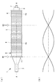
図示しない高周波電源からの高周波電力が積層体5に印加されると、積層体5が長手軸A方向の縦振動を発生し、発生された縦振動がボルト7を介してホーン3に伝達され、ホーン3の先端が長手軸A方向に振動する。このときに、縦振動が、ホーン3の基端から先端へ伝達する間に増幅されることによって、ホーン3の先端において大きな振幅の振動が得られる。ここで、高周波電力の周波数は、図2(a),(b)に示されるように、本体1の先端、中間位置および基端が縦振動の腹となるように、20kHz以上100kHz以下の範囲内から選択される。図2(a)において、矢印N1,N2が縦振動の節を示している。
When high frequency power from a high frequency power source (not shown) is applied to the
本体1はさらに、先端側の節N1の位置またはその近傍に、半径方向外方に突出し、高い熱伝導性を有する金属からなる環状のフランジ部11を備えている。すなわち、フランジ部11の、本体1への長手軸A方向の取り付け位置は、振動速度が0となる位置となっている。
また、金属体4と、フランジ11を有するホーン3との境界面Bでの縦振動の振動速度をV1とし、腹の位置での縦振動の振動速度をV2としたときに、振動速度比V1/V2は、0.05以上0.3以下であることが好ましい。振動速度比V1/V2が0.3よりも大きい場合には、ホーン3が、振動速度の速い位置において金属体4に接続されることによって、ズレ振動などの、本来の長手軸A方向の縦振動以外の振動が発生して発熱し易くなり、後述する放熱管2による放熱性能を十分に得られない可能性がある。一方、互いに異なる種類の金属同士の境界面Bを節N1に配置した場合には、強度不足になり得る。そのため、ホーン3と金属体4との境界面Bは、節N1から若干離れた、振動速度比V1/V2が0.05以上となる位置に配することが好ましい。
The
Further, when the vibration speed of the vertical vibration at the boundary surface B between the
放熱管2は、高い熱伝導性を有する金属からなる筒状であり、その先端の開口部からホーン3の先端部分を突出させた状態で本体1を収容している。放熱管2の外周面には、周方向に延びる多数の放熱フィン2aが長手軸A方向に間隔を空けて配列して設けられている。放熱管2は、フランジ部11の外周面に固定されている。
The
次に、このように構成された治療用超音波振動子10の作用について説明する。
本実施形態に係る治療用超音波振動子10は、生体内の組織に超音波振動を与えることによって組織の粉砕や溶解等の処置を行う超音波処置装置に搭載されるものである。超音波処置装置が備える高周波電源から、20kHz以上100kHz以下の範囲の周波数の高周波電力が積層体5に供給されると、積層体5が長手軸A方向の縦振動を発生し、ホーン3の先端が超音波振動する。したがって、超音波振動するホーン3の先端を患部に接触させることによって、患部の粉砕や溶解等の処置を行うことができる。
Next, the operation of the therapeutic
The therapeutic
この場合に、本実施形態によれば、積層体5に供給された高周波電力のうち、大部分は機械的振動に変化されるが、一部は熱に変換される。本体1において生じた熱は、金属体4,6に設けられた放熱溝4a,6aと本体1の外側に設けられた放熱管2とによって、該放熱管2の外部に放出され、さらに外筒14の外部に放出されるので、本体1の過熱が抑制される。特に、本体1のうち、歪み量が最大となる節N1,N2の位置において発熱量が最大となるが、節N1の位置に放熱管2がフランジ部11を介して本体1に連結されているので、本体1の熱が高効率で放熱管2を介して放出される。したがって、ホーン3の先端の振動振幅を増大して処置性能を高めるために、積層体5に供給する高周波電力を増大した場合にも、治療用超音波振動子10は、過熱することなく作動し続けることができ、高い処置性能を発揮し続けることができることができるという利点がある。
In this case, according to the present embodiment, most of the high-frequency power supplied to the
さらに、従来のBLT振動子は一般に、金属体としてチタン製を使用しているが、本実施形態に係る治療用超音波振動子10は、チタンよりもはるかに高い熱伝導率を有するアルミニウム製の金属体4,6を使用している。したがって、積層体5において発生した熱を、金属体4および放熱管2を介してさらに効率的に放出することができ、本体1全体の全長を短くすることができるという利点がある。
Furthermore, the conventional BLT vibrator generally uses titanium as the metal body, but the therapeutic
なお、本実施形態においては、図3(a),(b)に示されるように、第2の金属体6の基端面に、長手軸A方向に延びる複数の放熱フィン6bが間隔を空けて設けられていてもよい。図3(a),(b)の例では、放熱フィン6bは、長手軸Aを中心とする周方向に配列して設けられている。
本体1のうち、組織に対して仕事を行うのはホーン3の先端部分のみである。そこで、本体1の基端に放熱フィン6bを設けることによって、治療用超音波振動子10の処置動作に影響を与えることなく、治療用超音波振動子10の放熱性能をさらに向上することができる。
In this embodiment, as shown in FIGS. 3A and 3B, a plurality of radiating
Of the
また、本実施形態においては、縦振動の2つの節N1,N2のうち、先端側の節N1において本体1と放熱管2とをフランジ部11を介して接続することとしたが、これに代えて、またはこれに加えて、図4に示されるように、基端側の節N2において本体1と放熱管2とを接続してもよい。この場合、節N2は、積層体5に位置するので、2枚の圧電素子の間に挟まれた、圧電素子よりも大径の金属板12をさらに備え、該金属板12の、積層体5の外周面から半径方向にフランジ状に突出する周縁部分または外周面が、放熱管2と連結固定される。
このようにしても、図1(a),(b)に示される構成と同様の放熱効果を得ることができる。
In the present embodiment, the
Even if it does in this way, the heat dissipation effect similar to the structure shown by Fig.1 (a), (b) can be acquired.
(第2の実施形態)
次に、本発明の第2の実施形態に係る治療用超音波振動子20について図5から図7を参照して説明する。
本実施形態に係る治療用超音波振動子20は、放熱管2に代えて、ペルチェ素子13を備えている点において、第1の実施形態に係る治療用超音波振動子10と異なっている。したがって、本実施形態においては、ペルチェ素子13について主に説明し、その他の第1の実施形態と共通する構成については、同一の符号を付して説明を省略する。
(Second Embodiment)
Next, a therapeutic
The therapeutic
治療用超音波振動子20は、図5(a),(b)に示されるように、金属板12を備えている。金属板12は、図4に示される金属板12と同様である。金属板12の、積層体5の外周面から半径方向にフランジ状に突出する環状の周縁部分(フランジ部)12aには、複数個のペルチェ素子13が、その吸熱面が金属板12の表面と接触するように、周方向に並んで接着剤によって固定されている。各ペルチェ素子13は、図示しない電線を介して電流が供給されることによって、金属板12を介して積層体5から熱を吸収し、吸熱面と対向する放熱面から熱を放出するようになっている。
As shown in FIGS. 5A and 5B, the therapeutic
このように構成された治療用超音波振動子20によれば、積層体5への高周波電力の供給によって本体1において生じた熱は、ペルチェ素子13によって吸収され、該ペルチェ素子13の放熱面から放出され、さらに外筒14の外部に放出されるので、本体1の過熱が抑制される。特に、本体1のうち、発熱量が最大となる節N2の位置にペルチェ素子13が金属板12を介して接続されているので、本体1の熱が高効率でペルチェ素子13によって放出される。したがって、ホーン3の先端の振動振幅を増大して処置性能を高めるために、積層体5に供給する高周波電力を増大した場合にも、治療用超音波振動子20は、過熱することなく作動し続けることができ、高い処置性能を発揮し続けることができるという利点がある。その他の効果は、第1の実施形態と同様であるので、説明を省略する。
According to the therapeutic
なお、本実施形態においては、図6に示されるように、第2の金属体6の基端面にもペルチェ素子13が設けられていてもよい。図6には、ナットを兼ねた第2の金属体6が示されており、第2の金属体6の平坦な基端面にペルチェ素子13が固定されている。このようにすることで、治療用超音波振動子20の処置動作に影響を与えることなく、治療用超音波振動子20の放熱性能をさらに向上することができる。
In the present embodiment, as shown in FIG. 6, the
また、本実施形態においては、ペルチェ素子13を、本体1の基端側の節N2の位置に、金属板12を介して接続することとしたが、これに代えて、またはこれに加えて、図7に示されるように、本体1の先端側の節N1の位置に、ペルチェ素子13を接続してもよい。この場合、上述したフランジ部11の表面にペルチェ素子13を固定すればよい。
また、第1の実施形態において説明した放熱管2と、第2の実施形態において説明したペルチェ素子13とは、適宜組み合わせて用いてもよい。
In the present embodiment, the
Further, the
また、第1および第2の実施形態においては、放熱溝4a,6aおよび放熱フィン2aの形状は、適宜変更可能である。例えば、図8に示されるように、放熱溝4a,6aが、周方向に間隔を空けて長手軸A方向に形成されていてもよい。同様に、放熱フィン2aも、周方向に間隔を空けて長手軸A方向に形成されていてもよい。
In the first and second embodiments, the shapes of the
1 振動子本体
2 放熱管(放熱手段)
2a 放熱フィン
3 ホーン
4,6 金属体
4a,6a 放熱溝
5 積層体
6b 放熱フィン
7 ボルト
8 ナット
9 ボルト穴
10,20 治療用超音波振動子
11 フランジ部
12 金属板
12a 周縁部分(フランジ部)
13 ペルチェ素子(放熱手段)
1
13 Peltier element (heat dissipation means)
Claims (6)
先端側から長手軸に沿って順に、第1の金属体と、複数の圧電素子を分極方向が交互に逆方向となるように前記長手軸方向に積層してなる積層体と、第2の金属体とを有し、これらをボルトによって一体に締結してなる振動子本体と、
該振動子本体の、前記超音波振動の節となる位置またはその近傍に形成された半径方向外方に突出するフランジ部を介し、前記振動子本体の熱を該振動子本体の外部へ放出する放熱手段とを備える治療用超音波振動子。 A therapeutic ultrasonic transducer that generates ultrasonic vibrations having a frequency of 20 kHz to 100 kHz,
In order from the front end side along the longitudinal axis, a first metal body, a laminate in which a plurality of piezoelectric elements are laminated in the longitudinal axis direction so that the polarization directions are alternately reversed, and a second metal A vibrator body formed by integrally fastening them with bolts,
The heat of the vibrator main body is released to the outside of the vibrator main body through a flange portion protruding outward in the radial direction formed at or near the position of the ultrasonic vibration node of the vibrator main body. A therapeutic ultrasonic transducer comprising a heat radiating means.
前記第1の金属体と前記ホーンとの前記長手軸方向の接続位置は、前記超音波振動の腹の位置における振動速度に対する振動速度の比が0.05以上0.3以下となる位置である請求項1に記載の治療用超音波振動子。 The vibrator main body has a horn integrally connected to the first metal body on a distal end side of the first metal body;
The connection position in the longitudinal axis direction between the first metal body and the horn is a position where the ratio of the vibration speed to the vibration speed at the antinode position of the ultrasonic vibration is 0.05 or more and 0.3 or less. The therapeutic ultrasonic transducer according to claim 1.
Priority Applications (5)
| Application Number | Priority Date | Filing Date | Title |
|---|---|---|---|
| JP2014147803A JP5963811B2 (en) | 2014-07-18 | 2014-07-18 | Ultrasonic transducer for treatment |
| EP15822038.4A EP3170467A4 (en) | 2014-07-18 | 2015-06-22 | Ultrasonic vibrator for medical treatment |
| CN201580014012.2A CN106102622A (en) | 2014-07-18 | 2015-06-22 | Treatment ultrasonic oscillator |
| PCT/JP2015/067901 WO2016009788A1 (en) | 2014-07-18 | 2015-06-22 | Ultrasonic vibrator for medical treatment |
| US15/271,661 US20170007855A1 (en) | 2014-07-18 | 2016-09-21 | Thereapeutic ultrasonic transducer |
Applications Claiming Priority (1)
| Application Number | Priority Date | Filing Date | Title |
|---|---|---|---|
| JP2014147803A JP5963811B2 (en) | 2014-07-18 | 2014-07-18 | Ultrasonic transducer for treatment |
Publications (3)
| Publication Number | Publication Date |
|---|---|
| JP2016022136A JP2016022136A (en) | 2016-02-08 |
| JP2016022136A5 JP2016022136A5 (en) | 2016-06-16 |
| JP5963811B2 true JP5963811B2 (en) | 2016-08-03 |
Family
ID=55078289
Family Applications (1)
| Application Number | Title | Priority Date | Filing Date |
|---|---|---|---|
| JP2014147803A Active JP5963811B2 (en) | 2014-07-18 | 2014-07-18 | Ultrasonic transducer for treatment |
Country Status (5)
| Country | Link |
|---|---|
| US (1) | US20170007855A1 (en) |
| EP (1) | EP3170467A4 (en) |
| JP (1) | JP5963811B2 (en) |
| CN (1) | CN106102622A (en) |
| WO (1) | WO2016009788A1 (en) |
Families Citing this family (17)
| Publication number | Priority date | Publication date | Assignee | Title |
|---|---|---|---|---|
| US8182501B2 (en) | 2004-02-27 | 2012-05-22 | Ethicon Endo-Surgery, Inc. | Ultrasonic surgical shears and method for sealing a blood vessel using same |
| US8808319B2 (en) | 2007-07-27 | 2014-08-19 | Ethicon Endo-Surgery, Inc. | Surgical instruments |
| US8523889B2 (en) | 2007-07-27 | 2013-09-03 | Ethicon Endo-Surgery, Inc. | Ultrasonic end effectors with increased active length |
| US8512365B2 (en) | 2007-07-31 | 2013-08-20 | Ethicon Endo-Surgery, Inc. | Surgical instruments |
| US8430898B2 (en) | 2007-07-31 | 2013-04-30 | Ethicon Endo-Surgery, Inc. | Ultrasonic surgical instruments |
| US10010339B2 (en) | 2007-11-30 | 2018-07-03 | Ethicon Llc | Ultrasonic surgical blades |
| US8951272B2 (en) | 2010-02-11 | 2015-02-10 | Ethicon Endo-Surgery, Inc. | Seal arrangements for ultrasonically powered surgical instruments |
| US9820768B2 (en) | 2012-06-29 | 2017-11-21 | Ethicon Llc | Ultrasonic surgical instruments with control mechanisms |
| US10357303B2 (en) | 2015-06-30 | 2019-07-23 | Ethicon Llc | Translatable outer tube for sealing using shielded lap chole dissector |
| CN108430653B (en) | 2015-12-24 | 2021-04-27 | 奥林巴斯株式会社 | Ultrasonic vibrator |
| US10245064B2 (en) | 2016-07-12 | 2019-04-02 | Ethicon Llc | Ultrasonic surgical instrument with piezoelectric central lumen transducer |
| US10828056B2 (en) * | 2016-08-25 | 2020-11-10 | Ethicon Llc | Ultrasonic transducer to waveguide acoustic coupling, connections, and configurations |
| WO2018070044A1 (en) | 2016-10-14 | 2018-04-19 | オリンパス株式会社 | Vibration transmission body, ultrasonic transducer structure, and medical instrument |
| JP7030789B2 (en) * | 2016-11-16 | 2022-03-07 | インテグラ ライフサイエンシーズ エンタープライジーズ, エルエルエルピー | Ultrasound Surgery Handpiece |
| CN111491577B (en) * | 2017-11-10 | 2023-12-01 | 巴德股份有限公司 | Radiator for conduit and system and method thereof |
| CN111570244A (en) * | 2020-05-06 | 2020-08-25 | 盈甲医疗器械制造(上海)有限公司 | Ultrasonic transducer of ultrasonic surgical instrument and ultrasonic surgical instrument thereof |
| JPWO2022269971A1 (en) * | 2021-06-23 | 2022-12-29 |
Family Cites Families (20)
| Publication number | Priority date | Publication date | Assignee | Title |
|---|---|---|---|---|
| US3689783A (en) * | 1971-03-11 | 1972-09-05 | David A Williams | Ultrasonic transducer with half-wave separator between piezoelectric crystal means |
| JPH0767460B2 (en) * | 1986-03-28 | 1995-07-26 | オリンパス光学工業株式会社 | Ultrasonic treatment device |
| JPH0194841A (en) * | 1987-10-08 | 1989-04-13 | Olympus Optical Co Ltd | Ultrasonic treatment device |
| JPH0199547A (en) * | 1987-10-13 | 1989-04-18 | Olympus Optical Co Ltd | Ultrasonic treatment apparatus |
| US5076276A (en) * | 1989-11-01 | 1991-12-31 | Olympus Optical Co., Ltd. | Ultrasound type treatment apparatus |
| JP2660069B2 (en) * | 1989-11-07 | 1997-10-08 | オリンパス光学工業株式会社 | Ultrasound therapy equipment |
| JP2706541B2 (en) * | 1989-11-14 | 1998-01-28 | オリンパス光学工業株式会社 | Ultrasound therapy equipment |
| US5221282A (en) * | 1991-05-29 | 1993-06-22 | Sonokinetics Group | Tapered tip ultrasonic aspirator |
| US5843109A (en) * | 1996-05-29 | 1998-12-01 | Allergan | Ultrasonic handpiece with multiple piezoelectric elements and heat dissipator |
| US6013048A (en) * | 1997-11-07 | 2000-01-11 | Mentor Corporation | Ultrasonic assisted liposuction system |
| US6278218B1 (en) * | 1999-04-15 | 2001-08-21 | Ethicon Endo-Surgery, Inc. | Apparatus and method for tuning ultrasonic transducers |
| JP2001321388A (en) * | 2000-05-17 | 2001-11-20 | Aloka Co Ltd | Ultrasonic surgical tool |
| WO2004066856A1 (en) * | 2003-01-31 | 2004-08-12 | Hitachi Medical Corporation | Ultrasonic probe and ultrasonic device |
| EP1774920A4 (en) * | 2004-06-21 | 2011-01-05 | Hiroshi Furuhata | Ultrasonic brain infarction treating device |
| NL1026492C2 (en) * | 2004-06-24 | 2005-12-28 | Pan Consult B V | Device for ultrasound irradiating a target area in a human or animal body. |
| EP1806097B1 (en) * | 2004-10-27 | 2008-12-10 | Kabushiki Kaisha Toshiba | Ultrasonic probe and ultrasonic apparatus |
| US8808319B2 (en) * | 2007-07-27 | 2014-08-19 | Ethicon Endo-Surgery, Inc. | Surgical instruments |
| US8319400B2 (en) * | 2009-06-24 | 2012-11-27 | Ethicon Endo-Surgery, Inc. | Ultrasonic surgical instruments |
| US20110196438A1 (en) * | 2010-02-10 | 2011-08-11 | Lukas Mnozil | Therapy device and method for treating underlying tissue using electrical and acoustic energies |
| JP4856290B2 (en) * | 2010-03-31 | 2012-01-18 | オリンパスメディカルシステムズ株式会社 | Medical equipment |
-
2014
- 2014-07-18 JP JP2014147803A patent/JP5963811B2/en active Active
-
2015
- 2015-06-22 EP EP15822038.4A patent/EP3170467A4/en not_active Withdrawn
- 2015-06-22 WO PCT/JP2015/067901 patent/WO2016009788A1/en active Application Filing
- 2015-06-22 CN CN201580014012.2A patent/CN106102622A/en active Pending
-
2016
- 2016-09-21 US US15/271,661 patent/US20170007855A1/en not_active Abandoned
Also Published As
| Publication number | Publication date |
|---|---|
| EP3170467A1 (en) | 2017-05-24 |
| EP3170467A4 (en) | 2018-03-21 |
| WO2016009788A1 (en) | 2016-01-21 |
| CN106102622A (en) | 2016-11-09 |
| JP2016022136A (en) | 2016-02-08 |
| US20170007855A1 (en) | 2017-01-12 |
Similar Documents
| Publication | Publication Date | Title |
|---|---|---|
| JP5963811B2 (en) | Ultrasonic transducer for treatment | |
| JP2016022136A5 (en) | ||
| US7405510B2 (en) | Thermally enhanced piezoelectric element | |
| US8446071B2 (en) | Thermally enhanced ultrasound transducer system | |
| JP4838781B2 (en) | Ultrasonic vibrator and manufacturing method thereof | |
| US8378557B2 (en) | Thermal transfer and acoustic matching layers for ultrasound transducer | |
| JP2002542005A (en) | Ultrasonic transducer with improved transmission of compression pressure | |
| US7378779B2 (en) | Thermally enhanced piezoelectric composite system and method | |
| US8237335B2 (en) | Thermally enhanced ultrasound transducer means | |
| JP6261833B2 (en) | Ultrasonic vibrator, ultrasonic treatment device, and ultrasonic therapy apparatus | |
| ES2392946T3 (en) | Ultrasonic bar transducer for ultrasonic generation in liquids | |
| JP2010089007A (en) | Ultrasonic machining apparatus | |
| US10060422B2 (en) | Device and arrangement for generating a flow of air | |
| JP4827170B2 (en) | Bolt tightened Langevin type vibrator | |
| TW201545818A (en) | Ultrasonic converter | |
| JP2004312119A (en) | Ultrasonic transducer | |
| JP4419874B2 (en) | Ultrasonic beauty equipment | |
| JP6176834B2 (en) | Thermal drain of ultrasonic probe | |
| JP2002282788A (en) | Ultrasonic wave generator | |
| TWI376246B (en) | Hand-held transducer for low-frequency ultrasonic waves | |
| JP3772601B2 (en) | Ultrasonic generator | |
| JP2006319404A (en) | Ultrasonic transducer | |
| JP3171548U (en) | Piezoelectric vibration device with heat dissipation and heat conduction functions | |
| US20070055182A1 (en) | Thermally enhanced ultrasound transducer method | |
| JP4419774B2 (en) | Ultrasonic beauty equipment |
Legal Events
| Date | Code | Title | Description |
|---|---|---|---|
| A521 | Request for written amendment filed |
Free format text: JAPANESE INTERMEDIATE CODE: A523 Effective date: 20160427 |
|
| A621 | Written request for application examination |
Free format text: JAPANESE INTERMEDIATE CODE: A621 Effective date: 20160427 |
|
| A871 | Explanation of circumstances concerning accelerated examination |
Free format text: JAPANESE INTERMEDIATE CODE: A871 Effective date: 20160427 |
|
| A975 | Report on accelerated examination |
Free format text: JAPANESE INTERMEDIATE CODE: A971005 Effective date: 20160527 |
|
| TRDD | Decision of grant or rejection written | ||
| A01 | Written decision to grant a patent or to grant a registration (utility model) |
Free format text: JAPANESE INTERMEDIATE CODE: A01 Effective date: 20160614 |
|
| A61 | First payment of annual fees (during grant procedure) |
Free format text: JAPANESE INTERMEDIATE CODE: A61 Effective date: 20160628 |
|
| R151 | Written notification of patent or utility model registration |
Ref document number: 5963811 Country of ref document: JP Free format text: JAPANESE INTERMEDIATE CODE: R151 |
|
| R250 | Receipt of annual fees |
Free format text: JAPANESE INTERMEDIATE CODE: R250 |
|
| R250 | Receipt of annual fees |
Free format text: JAPANESE INTERMEDIATE CODE: R250 |
|
| R250 | Receipt of annual fees |
Free format text: JAPANESE INTERMEDIATE CODE: R250 |
|
| R250 | Receipt of annual fees |
Free format text: JAPANESE INTERMEDIATE CODE: R250 |
|
| R250 | Receipt of annual fees |
Free format text: JAPANESE INTERMEDIATE CODE: R250 |