JP5962498B2 - Operation device for hull sorter - Google Patents
Operation device for hull sorter Download PDFInfo
- Publication number
- JP5962498B2 JP5962498B2 JP2012281083A JP2012281083A JP5962498B2 JP 5962498 B2 JP5962498 B2 JP 5962498B2 JP 2012281083 A JP2012281083 A JP 2012281083A JP 2012281083 A JP2012281083 A JP 2012281083A JP 5962498 B2 JP5962498 B2 JP 5962498B2
- Authority
- JP
- Japan
- Prior art keywords
- circulation
- rice
- discharge
- sorting
- switching valve
- Prior art date
- Legal status (The legal status is an assumption and is not a legal conclusion. Google has not performed a legal analysis and makes no representation as to the accuracy of the status listed.)
- Expired - Fee Related
Links
Images


Landscapes
- Adjustment And Processing Of Grains (AREA)
Description
この発明は、揺動選別板型籾摺選別機の操作装置に関するものである。 The present invention relates to an operating device for a swing sorting plate type hulling sorter.
籾摺部、摺落米風選部、揺動選別板型の混合米選別部を備えた籾摺選別機において、混合米選別部に混合米タンクを吊り下げ支持して貯溜穀粒量の増減により上下動するように構成し、混合米タンクと混合米選別部の循環/排出切換弁とをメカ的なリンケージで連結する切換手段により連動連結し、混合米タンクに所定量以上の穀粒が溜り下方へ移動すると、循環/排出切換弁を循環側から排出側に切り換え、また、混合米タンクに所定量以下の穀粒が溜り上方へ移動すると循環/排出切換弁を排出側から循環側に切り換えようにしものは、公知である(特許文献1)。 In a rice hull sorter equipped with a rice huller, a crushed rice-style batter, and a mixed rice sorter with a rocking sorter type, the mixed rice tank is suspended and supported by the mixed rice sorting unit to increase or decrease the amount of stored grains The mixed rice tank and the circulation / discharge switching valve of the mixed rice sorting section are interlocked with each other by a switching means that is connected by a mechanical linkage, and a predetermined amount or more of grains are contained in the mixed rice tank. When moving downward, the circulation / discharge switching valve is switched from the circulation side to the discharging side, and when a predetermined amount or less of the grain has accumulated in the mixed rice tank and moved upward, the circulation / discharge switching valve is moved from the discharging side to the circulation side. Switching is well known (Patent Document 1).
背景技術の発明は、籾摺選別機を通電状態とする電源スイッチと作業進行を司る操作レバーを備え、電源スイッチのON操作により籾摺選別機を通電状態として空運転を開始し、次いで、操作レバーにより籾シャッタ弁を開調節,循環/排出切換弁を循環側に切り換えて籾摺選別作業を開始する。そして、混合米選別部の混合米タンクの貯溜穀粒量が所定量になると混合米選別部の揺動選別板が適正選別状態であると判定し、メカ的な切換手段により循環/排出切換弁を循環側から排出側に切り換え選別玄米を機外に取り出す構成である。 The invention of the background art has a power switch for energizing the hull sorter and an operation lever for controlling the work progress, and when the power switch is turned on, the hull sorter is energized to start idling, The hull shutter valve is opened by the lever, and the circulation / discharge switching valve is switched to the circulation side to start the hull sorting operation. When the amount of stored grains in the mixed rice tank of the mixed rice sorting unit reaches a predetermined amount, it is determined that the swing sorting plate of the mixed rice sorting unit is in an appropriate sorting state, and the circulation / discharge switching valve is operated by a mechanical switching means. Is switched from the circulation side to the discharge side, and the selected brown rice is taken out of the machine.
前記構成では、籾摺作業開始時に循環/排出切換弁を自動的に循環側から排出側に切り換えることができオペレータの操作を軽減できるメリットはあるが、その反面オペレータ
の意図に反し遅れて循環/排出切換弁が循環側から排出側へ切り換えられることがあり、オペレータの好みに合わせた循環/排出切換弁の切り換えができないという問題点があった。
In the above-described configuration, the circulation / discharge switching valve can be automatically switched from the circulation side to the discharge side at the start of the hulling operation, and there is a merit that the operation of the operator can be reduced. There is a problem that the discharge switching valve may be switched from the circulation side to the discharge side, and the circulation / discharge switching valve cannot be switched according to the preference of the operator.
そこで、本発明は、籾摺作業開始時に循環/排出切換弁を自動的に循環側から排出側に切り換えるものでありながら、オペレータの好みに合わせた早いタイミングで循環/排出切換弁を循環側から排出側へ切り換えるようにし排出籾摺選別作業を迅速に開始しようとするものである。 Therefore, the present invention automatically switches the circulation / discharge switching valve from the circulation side to the discharge side at the start of the hulling operation, but the circulation / discharge switching valve is moved from the circulation side at an early timing according to the preference of the operator. By switching to the discharge side, the discharge hull sorting operation is started quickly.
前記問題点を解決するために、本発明は次のような技術的手段を講じた。
請求項1の発明は、籾摺部(1)、摺落米風選部(2)、揺動選別板型の混合米選別部(3)と、駆動用主モータ(M1)を備えた籾摺選別機において、前記籾摺部(1)には籾供給調節弁(31)付きの籾ホッパ(6)と、籾摺装置(7,7)を設け、前記混合米選別部(3)には前記摺落米風選部(2)からの風選混合米を一時貯溜して混合米選別部(3)の揺動選別板(15)に供給する混合米タンク(24)と、揺動選別板(15)の揺動駆動装置への動力の入切をする揺動入切クラッチ(49a)と、揺動選別板(15)の選別玄米を機内循環側あるいは機外排出側に切り換える循環/排出切換弁(36)を設け、前記循環/排出切換弁(36)を切換作動する循環/排出切換弁切換モータ(M2)を設け、前記籾供給調節弁(31)及び揺動入切クラッチ(49a)操作用の操作レバー(32)を操作溝(43)の初期位置(43a,43m)から第1操作位置(43b,43n)に操作可能に構成し、操作レバー(32)を第1操作位置(43b,43n)に操作すると前記籾供給調節弁(31)を開調節し揺動入切クラッチ(49a)を入りにするように構成し、操作溝(43)の第1操作位置(43b,43m)には操作検出用の籾摺選別作業検出センサ(SE3)を設け、前記主モータ(M1)の負荷電流値を検出する負荷電流センサ(SE5)を設け、制御部(51)には、操作レバー(32)を第1操作位置(43b,43n)に操作時に、前記負荷電流センサ(SE5)の検出負荷電流値が、所定しきい値(VK)を超えた状態で且つ所定時間内に所定の積算値を超えると、籾摺選別作業の安定と判定し、循環/排出切換弁(36)を循環側から排出側に切り換える機能を備えていることを特徴とする籾摺選別機の操作装置とする。
In order to solve the above problems, the present invention has taken the following technical means.
The invention of
請求項1の発明によると、
籾摺部(1)、摺落米風選部(2)、揺動選別板型の混合米選別部(3)と、駆動用主モータ(M1)を備えた籾摺選別機において、前記籾摺部(1)には籾供給調節弁(31)付きの籾ホッパ(6)と、籾摺装置(7,7)を設け、前記混合米選別部(3)には前記摺落米風選部(2)からの風選混合米を一時貯溜して混合米選別部(3)の揺動選別板(15)に供給する混合米タンク(24)と、揺動選別板(15)の揺動駆動装置への動力の入切をする揺動入切クラッチ(49a)と、揺動選別板(15)の選別玄米を機内循環側あるいは機外排出側に切り換える循環/排出切換弁(36)を設け、前記循環/排出切換弁(36)を切換作動する循環/排出切換弁切換モータ(M2)を設け、前記籾供給調節弁(31)及び揺動入切クラッチ(49a)操作用の操作レバー(32)を操作溝(43)の初期位置(43a,43m)から第1操作位置(43b,43n)に操作可能に構成し、操作レバー(32)を第1操作位置(43b,43n)に操作すると前記籾供給調節弁(31)を開調節し揺動入切クラッチ(49a)を入りにするように構成し、操作溝(43)の第1操作位置(43b,43m)には操作検出用の籾摺選別作業検出センサ(SE3)を設け、前記主モータ(M1)の負荷電流値を検出する負荷電流センサ(SE5)を設け、制御部(51)には、操作レバー(32)を第1操作位置(43b,43n)に操作時に、前記負荷電流センサ(SE5)の検出負荷電流値が、所定しきい値(VK)を超えた状態で且つ所定時間内に所定の積算値を超えると、籾摺選別作業の安定と判定し、循環/排出切換弁(36)を循環側から排出側に切り換える機能を備えていることを特徴とする籾摺選別機の操作装置とするので、
構成を簡素化しコストの低減をしながら、籾摺選別作業開始時に負荷電流センサ(SE5)の検出値に基づき循環/排出切換弁(36)を切り換えて循環籾摺選別作業から排出籾摺選別作業に自動的に切り換えることができる。
According to the invention of
In a rice hull sorter comprising a hulling portion (1), a sliding rice wind sorting portion (2), a rocking sorting plate type mixed rice sorting portion (3), and a driving main motor (M1), The sliding portion (1) is provided with a straw hopper (6) with a straw supply control valve (31) and a straw sliding device (7, 7). The mixed rice tank (24) for temporarily storing the wind-selected mixed rice from the section (2) and supplying it to the rocking sorting plate (15) of the mixed rice sorting section (3), and the rocking of the rocking sorting plate (15) A swing on / off clutch (49a) for turning on / off power to the dynamic drive device and a circulation / discharge switching valve (36) for switching the sorted brown rice of the swing sorting plate (15) to the in-machine circulation side or the out-of-machine discharge side. A circulation / discharge switching valve switching motor (M2) for switching the circulation / discharge switching valve (36) is provided, and the soot supply control valve (31) and the swing on / off switch are operated. The operation lever (32) for operating the switch (49a) is configured to be operable from the initial position (43a, 43m) of the operation groove (43) to the first operation position (43b, 43n), and the operation lever (32) is configured. When operated to the first operation position (43b, 43n), the rod supply control valve (31) is adjusted to open and the swing on / off clutch (49a) is engaged, and the first operation of the operation groove (43) is performed. The position (43b, 43m) is provided with a hull sorting operation detection sensor (SE3) for operation detection, a load current sensor (SE5) for detecting a load current value of the main motor (M1), and a control unit (51 ), When the operating lever (32) is operated to the first operating position (43b, 43n), the load current value detected by the load current sensor (SE5) exceeds a predetermined threshold value (VK) and When a predetermined integrated value is exceeded within a predetermined time Stability and determines the hulling sorting work, since it is an operation device for hulling sorter, characterized in that a function for switching the discharge side circulation / discharge switching valve (36) from the circulation side,
While simplifying the configuration and reducing the cost, the circulation / discharge switching valve (36) is switched based on the detected value of the load current sensor (SE5) at the start of the hull sorting operation to change the recycle waste hull sorting operation to the discharged hull sorting operation. Can be switched automatically .
以下、図面に示すこの発明の実施例について説明する。
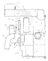
まず、図1及び図2に基づきこの発明を備えた籾摺選別機の全体構成について説明する。
Embodiments of the present invention shown in the drawings will be described below.
First, based on FIG.1 and FIG.2, the whole structure of the hulling sorter provided with this invention is demonstrated.
籾摺選別機は、機体の左側上部に配設している籾摺部1と、籾摺部1の下方に配設している摺落米風選部2と、籾摺部1及び摺落米風選部2の右側に配設している揺動選別板型の混合米選別部3と、摺落米風選部2の選別摺落米を揚穀する混合米揚穀機4と、混合米選別部3の選別玄米を機外に取り出す玄米揚穀機5と、混合米選別部3の選別籾を籾摺部1に揚穀還元する籾揚穀機27とにより構成されている。
The rice hull sorter includes a
籾摺部1は例えば籾摺ロール型に構成されていて、籾ホッパ6と、一対の籾摺ロール7,7と、籾摺ロール7,7の下方に設けられている振動型の摺落米移送棚8等により構成されている。籾ホッパ6の籾は籾摺ロール7,7で籾摺されて摺落米移送棚8に落下供給され、振動している摺落米移送棚8により右側に移送され、摺落米風選部2の下部の選別始端側に供給される。
The
摺落米風選部2は、摺落米風選箱体9と、摺落米風選箱体9内に上下方向に沿うように構成されている摺落米選別風路10と、摺落米選別風路10の中途部下方に設けられている粃受樋11と、摺落米選別風路10の始端部である下側部に設けられている摺落米受樋12と、摺落米選別風路10の終端側上側部に配設されている吸引ファン13と、排塵筒14等により構成されている。
The sliding rice
次に、揺動選別型混合米選別部3について説明する。
多段の揺動選別板15,…には、板面に選別用の凹凸が形成されていて、縦方向の一側を高い供給側、他側を低い排出側とし、縦方向に直交する横方向の一方側を高い揺上側、反対側を低い揺下側として、揺動選別板15の縦横2方向ともに傾斜した構成とし、揺動装置(図示省略)により揺動選別板15,…を揺動するように構成している。
Next, the swing sorting type mixed
The multistage oscillating
揺動選別板15,…の上方には混合米タンク24が配設されていて、摺落米受樋12に風選された混合米が混合米揚穀機4により揚穀されて混合米タンク24に供給され、次いで、分配供給樋16、分配ケース17を経由して揺動選別板15,…に供給される構成である。
A mixed
揺動選別板15,…に供給された混合米は、粒形の大小,比重の大小,摩擦係数の大小等の関係で、比重の重い小形の玄米は揺上側に偏流分布し、玄米に比較して大形で比重の軽い籾は、揺下側に偏流分布し、その中間部には分離されない籾・玄米の混合米が偏流分布しながら選別される。そして、これらの選別穀粒は、揺動選別板15の排出側に対向して設けられている玄米仕切板18及び籾仕切板19で仕切られて取り出される。
The mixed rice supplied to the oscillating
取り出された選別玄米は、玄米取出樋20,玄米流路21,玄米揚穀機5を経て機外に取り出される。また、取り出された選別混合米は混合米取出樋22,混合米流路23,摺落米受樋12に取り出され、次いで混合米揚穀機4,混合米タンク24,分配供給樋16,分配ケース17を経て、揺動選別板15,…に再度供給され再選別される。
The extracted sorted brown rice is taken out of the machine through the brown
また、揺動選別板15,…の揺下側に偏流分離した選別籾のうち揺下側の側壁に沿って流下する選別籾は側壁の切除開口部から取り出され籾取出樋25に取り出される。また、揺下側の側壁よりも揺上側を偏流流下した選別籾は揺動選別板15,…の排出側端部から流下し籾仕切板18により仕切られ籾取出樋25に取り出される。このようにして取り出された選別籾は、籾流路26,籾揚穀機27を経て籾摺部1に揚穀還元され再度籾摺される。なお、摺落米風選部2で粃受樋11に選別された粃は、籾揚穀機27に送られ、混合米選別部3の選別籾と共に籾摺部1に揚穀還元される。
Further, the sorting soot that flows down along the side wall of the swinging side among the sorting soot that has flow-separated to the swinging side of the
摺落米風選部2の下方に主モータM1を配設し、主モータM1から伝動装置(図示省略)を経由して籾摺部1,摺落米風選部2,混合米選別部3,混合米揚穀機4,玄米揚穀機5及び籾揚穀機27の回転各部に駆動するように構成している。
A main motor M1 is disposed below the sliding rice
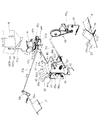
次に、図3に基づき操作レバー32及び混合米タンク24の穀粒溜まり具合に基づく籾供給調節弁31の調節作動構成について説明する。
籾ホッパ6の下部には籾供給調節弁31を設けている。混合米揚穀機4上部の揚穀投げ出し部には、混合米タンク24をバネ34により上下動自在に吊り下げ支持し、混合米タンク24は穀粒が溜まり重くなるとバネ34に抗して下方へ移動し、穀粒が少なくなり軽くなると上方へ移動するように構成している。
Next, the adjustment operation configuration of the koji supply
At the bottom of the heel hopper 6, a heel
混合米タンク24の側方に混合米大検出センサSE1a,混合米小検出センサSE1bを設け、混合米大検出センサSE1aにより所定量以上の混合米の溜りを検出し、混合米小検出センサSE1bにより少量の混合米の溜りを検出するようにしている。
A mixed rice large detection sensor SE1a and a mixed rice small detection sensor SE1b are provided on the side of the
また、混合米選別部3の選別穀粒取出部には、循環/排出切換弁36を設け、循環/排出切換弁切換モータM2の正逆回転駆動により揺動選別板15の選別玄米を機内循環側に切り換えたり、機外取出側に切り換えるようにしている。循環/排出切換弁36の循環側,排出側への切換状態を検出する循環/排出切換弁検出センサSE2を設けている。
In addition, a circulation /
また、混合米タンク24と籾供給調節弁31とをメカ的なリンケージで連結する連動調節手段37により連動連結している。この連動調節手段37は、例えば、混合米タンク24に一端が連結されている誘導ロッド37aと、誘導ロッド37aの他端にピン連結されている第1支点アーム37bと、第1支点アーム37bの他端にピン連結している連動ロッド37cと、連動ロッド37cの他端にピン連結している第2支点アーム37dと、第2支点アーム37dの他端にピン連結している第2連動ロッド37eとにより構成している。第2連動ロッド37eの他端に籾供給調節弁31の軸部31aにおけるアーム31bの一端をピン連結し、アーム31bの他端にはバネ38を連結し、籾供給調節弁31を開調節側に回動付勢している。
In addition, the
しかして、混合米タンク24に穀粒が溜り下方へ移動すると、誘導ロッド37a,第1
支点アーム37b,連動ロッド37c,第2支点アーム37d及び第2連動ロッド37eを介して籾供給調節弁31が閉調節される。また、混合米タンク24の穀粒量が減少し上方へ移動すると籾供給調節弁31が開調節される。そして、混合米タンク24の底部には開閉弁を設けず、分配供給樋16に混合米が流下して溜り所定層厚を保持しながら順次移送され揺動選別板15,…に連続的に供給されるように構成している。
Thus, when the grains accumulate in the
The saddle
機体の左右中間部のフレーム部に操作レバー32を配設している。フレーム部上部にはカバー41を設けて籾摺部1と混合米選別部3の空間部を閉鎖し、フレーム部には左右方向の軸42を支架している。軸42の中間部の支持部には操作レバー32の下端部を左右方向及び前後方向に回動自在に支持し、平面視U字型の案内溝43には手前側左右中央に初期位置43aを、左側前方に第1操作位置43bを、右側前方に第2操作位置43cを設けている。第1操作位置43bには籾摺選別作業検出センサSE3を設け、第2操作位置43cには循環/排出切換弁切換検出センサSE4を設けている。
An
軸42の操作レバー32の左右両側方部に第1操作体44,第2操作体45をそれぞれ回動自在に軸支し、第1操作体44,第2操作体45の上部屈折部に係止凹部44a,45aを設けている。操作レバー32を左右に傾動すると係止凹部44a,45aに係合し、第1操作体44,第2操作体45が回動操作可能になる。
A
第1操作体44と連動調節手段37との間を連動操作手段46を介して連動連結し、操作レバー32を初期位置43aから左側に傾動して第1操作体44に係合し第1操作位置43bに操作すると、籾摺選別作業検出センサSE3が第1操作位置43bへの移動操作を検出し、第1操作体44,連動操作手段46を介して連動調節手段37を作動し、籾供給調節弁31を開調節するように構成している。
The
すなわち、連動操作手段46は、第1操作体44の下側部に長孔とピンとで構成している融通手段46aと、融通手段46aに一端側が連繋されている第1操作ロッド46bと、第1操作ロッド46bの他端側にピン連結されている操作支点アーム46cとで構成している。そして、操作支点アーム46cの他端側を第2支点アーム37dの他端側にピン連結し、連動操作手段46と連動調節手段37を連動連結し、操作レバー32により籾供給調節弁31を開調節可能に構成し、且つ、混合米タンク24の穀粒の溜り具合により籾供給調節弁31を開閉調節するように構成している。
That is, the interlocking operation means 46 includes an accommodation means 46a formed of a long hole and a pin on the lower side portion of the
また、揺動選別板15,…の下方には主モータM1で駆動される揺動駆動装置48を設け、フレーム部に軸支している揺動クラッチアーム49の揺動クラッチプーリ49aを揺動駆動装置48の伝動ベルトに圧接したり離脱することにより揺動クラッチを入切するようにしている。
Further, a
第1操作体44の上側長孔部に揺動クラッチワイヤ50の一端をピン連結し、他端側を揺動クラッチアーム49に連結している。第1操作体44を第1操作位置43bに移動操作し籾供給調節弁31を開調節すると、揺動クラッチプーリ49aが入り状態となるように関連作動するようにしている。
One end of the swing
しかして、操作レバー32で第1操作体44を第1操作位置43bに操作すると、籾供給調節弁31を開調節し、揺動入切クラッチ49aを入りとし、第1操作体44の端部が籾摺選別作業検出センサSE3に当接し操作状態を検出すると、制御部51の循環側切換指令により循環/排出切換弁36は循環側に切り換えられる。
Accordingly, when the
また、操作レバー32を第1操作体44に係合一体化した状態で第1操作位置43bから初期位置43aに操作すると、籾供給調節弁31を閉調節状態で揺動入切クラッチ49
aを切り状態となり(なお、この状態で、混合米タンク24の穀粒の溜り具合により連動調節手段37を介して籾供給調節弁31は開閉調節される)、循環/排出切換弁36の循環側への切換状態は保持される。
Further, when the
a is turned off (in this state, the straw
また、操作レバー32を初期位置43aで右側に傾動し第2操作体45と係合一体化し第2操作位置43cに操作すると、第2操作体45の端部が循環/排出切換弁切換検出センサSE4に当接して検出されると、循環/排出切換弁36を切換可能状態となり、制御部51の排出側切換指令により循環/排出切換弁36は循環側から排出側に切り換えられるように構成している。
Further, when the operating
また、操作レバー32を第1操作位置43bに操作した後に操作レバー32を所定時間内に第2操作位置43bに操作されない場合には、制御部51の排出側切換指令により所定のタイミングで循環/排出切換弁36を循環側から排出側に切り換えるように構成している。例えば、混合米大検出センサSE1aの検出情報により混合米タンク24に所定量以上の混合米が溜り揺動選別板15の選別状態が安定したと判定すると、制御部51の排出側切換指令に基づき循環/排出切換弁36を循環側から排出側に切り換え選別玄米を自動排出するようにしている。
Further, when the
また、第2操作体45には復帰バネ52を介装し、操作レバー32を第2操作位置43cに操作した後に手を離すと、復帰バネ52により第2操作体45は第2操作位置43cから離脱し、初期位置43a側に戻されるように構成している。
Further, a
次に、図2,図4に基づき操作盤56について説明する。
籾摺選別機の例えば正面中央の摺落米風選部2の上部には操作盤56を設けている。操作盤56の下側中央部に運転開始スイッチSW1,運転停止スイッチSW2を設け、下側右側部に電源入切表示ランプ57を設けている。上側右側部には左右両側に循環/排出切換弁手動切換スイッチSW3,該スイッチSW3の入切を表示する手動表示ランプSW3R、循環/排出切換弁自動切換スイッチSW4,該スイッチSW4の入切を表示する自動スイッチ表示ランプSW4Rを設け、両スイッチSW3、SW4の中間部に、循環籾摺作業状態を表示する循環作業表示ランプ58と,排出籾摺選別作業状態を表示する排出作業表示ランプ59を設け、左側部に主モータM1の負荷電流値を表示する負荷電流値表示部60を設けている。
Next, the operation panel 56 will be described with reference to FIGS.
An operation panel 56 is provided on the upper part of the slashed rice
次に、図5に基づき制御ブロック図について説明をする。
制御部51の入力側には、スイッチ群及びセンサ群を接続している。すなわち、運転開始スイッチSW1,運転停止スイッチSW2,循環/排出切換弁手動切換スイッチSW3,循環/排出切換弁自動切換スイッチSW4、及び、混合米大検出センサSE1a,混合米小検出センサSE1b、循環/排出切換弁検出センサSE2、籾摺選別作業検出センサSE3、循環/排出切換弁切換検出センサSE4,主モータM1の負荷電流値を検出する負荷電流センサSE5を入力インターフェイスを経由して接続している。
Next, a control block diagram will be described with reference to FIG.
A switch group and a sensor group are connected to the input side of the control unit 51. That is, the operation start switch SW1, the operation stop switch SW2, the circulation / discharge switching valve manual switching switch SW3, the circulation / discharge switching valve automatic switching switch SW4, the mixed rice large detection sensor SE1a, the mixed rice small detection sensor SE1b, A discharge switching valve detection sensor SE2, a hull sorting operation detection sensor SE3, a circulation / discharge switching valve switching detection sensor SE4, and a load current sensor SE5 for detecting the load current value of the main motor M1 are connected via an input interface. .
また、出力側には駆動回路を経由して主モータM1,循環/排出切換弁制御モータM2,ロール間隙制御モータM3、及び、電源入切表示ランプ57,循環作業表示ランプ58,排出作業表示ランプ59,負荷電流値表示部60,循環/排出切換弁手動切換スイッチ表示ランプSW3R,自動スイッチ表示ランプSW4Rを接続している。
(1615)
次に、図7に基づき他の実施例について説明する。
On the output side, a main motor M1, a circulation / discharge switching valve control motor M2, a roll gap control motor M3, a power on / off
(1615)
Next, another embodiment will be described with reference to FIG.
案内溝43には左側部に始動籾摺作業位置43mを,右側部に排出籾摺作業位置43nを設けて、操作レバー32を往復操作自在に構成している。操作レバー32を始動籾摺作
業位置43mに操作すると、籾摺選別作業検出センサSE3がON検出し、籾ホッパ6の籾供給調節弁31が開調節され、揺動クラッチプーリ49aがクラッチ入り状態となり、制御部51の循環/排出切換弁循環側切換指令に基づき循環/排出切換弁36が循環側に切り換えられて循環籾摺作業が開始されるようにしている。
The
また、操作レバー32を排出籾摺作業位置43nに操作すると循環/排出切換弁切換検出センサSE4がON検出し、籾供給調節弁31が開調節状態、揺動クラッチプーリ49aがクラッチ入り状態を保持し制御部51の循環/排出切換弁排出側切換指令に基づき循環/排出切換弁36が循環側から排出側に切り換えられるように構成している。
Further, when the
また、循環/排出切換弁自動切換スイッチSW4がON操作されていて循環/排出切換弁36を自動切換中の場合には、操作レバー32が始動籾摺作業位置43mへ操作され籾摺選別作業検出センサSE3がON検出すると、図8に示すように負荷電流センサSE5で主モータM1の負荷電流値の検出を開始し、所定のしきい値(VK)を超えると籾摺選別開始状態と判定し、所定時間にわたり負荷電流値を積算し所定上積算値を超えると揺動選別板15の選別安定状態と判定し、混合米上検出センサSE1aが所定量の混合米の溜りを検出する以前でも制御部51の循環/排出切換弁排出側切換指令に基づき、循環/排出切換弁36を循環側から排出側に切り換え選別玄米を機外に排出するようにしている。
When the circulation / discharge switching valve automatic switch SW4 is turned ON and the circulation /
なお、負荷電流センサSE5の検出負荷電流値で揺動選別板15の選別安定状態を判定するにあたり、連続して前記しきい値(VK)を超えている状態で所定時間経過すると揺動選別板15の選別安定状態と判定してもよい。
In determining the sorting stable state of the
また、所定のしきい値(VK)を超えた状態の籾摺選別状態で所定時間にわたり負荷電流値を積算し所定下積算値より下降すると籾ホッパ6あるいは混合米ホッパ24の穀粒減少と判定し、混合米上検出センサSE1aが所定量以下の混合米の溜りを検出する以前でも制御部51の循環/排出切換弁排出側切換指令に基づき、循環/排出切換弁36を排出側から循環側に切り換え選別玄米を機内循環とするようにしている。
In addition, when the load current value is integrated over a predetermined time in the state where the predetermined threshold (VK) is exceeded and the load current value falls below the predetermined lower integrated value, it is determined that the grain of the rice hopper 6 or the
なお、負荷電流センサSE5の前記積算検出負荷電流値が所定の積算値に到達する以前に混合米大検出センサSE1aが所定量の混合米の溜りを検出すると、制御部51の循環/排出切換弁排出側切換指令により、選別玄米を機外に排出するようにしている。 If the mixed rice size detection sensor SE1a detects the accumulation of a predetermined amount of mixed rice before the integrated detected load current value of the load current sensor SE5 reaches a predetermined integrated value, the circulation / discharge switching valve of the control unit 51 is detected. The sorting brown rice is discharged out of the machine by the discharge side switching command.
また、循環/排出切換弁手動切換スイッチSW3がON操作されていて循環/排出切換弁36を手動切換の場合には、操作レバー32が排出籾摺作業位置43nに操作されると、制御部51の循環/排出切換弁排出側切換指令により循環/排出切換弁36が循環側から排出側に切り換えられ、オペレータの好みにより循環/排出切換弁36を排出側に切り換えることができる。
In addition, when the circulation / discharge switching valve manual switch SW3 is turned ON and the circulation /
前記構成によると、籾摺作業開始時における循環籾摺作業時間を負荷電流センサSE5の検出負荷電流値あるいは混合米大検出センサSE1aの検出情報により排出側切換状態を判定し制御部51の循環/排出切換弁排出側切換指令により選別玄米を機外に排出するので、循環籾摺作業時間を短縮し能率的に籾摺作業をすることができる。
また、循環/排出切換弁36の循環側から排出側への前記自動切換制御において、循環籾摺作業時間における負荷電流センサSE5の検出負荷電流値が所定値に到達する以前に混合米大検出センサSE1aが所定量の混合米の溜りを検出した場合には、所定負荷電流値を混合米大検出センサSE1aの所定量検出時点の検出負荷電流値まで基準値を減少補正し、次回籾摺作業から減少補正した基準値に基づき循環/排出切換弁36を循環側から排出側への切り換えをするようにしている。
According to the above-described configuration, the circulation-side hulling operation time at the start of the hulling operation is determined based on the detection load current value of the load current sensor SE5 or the detection information of the mixed rice size detection sensor SE1a, and the control unit 51 performs the circulation / Since the sorted brown rice is discharged out of the machine by the discharge switching valve discharge side switching command, it is possible to reduce the time required for the circulating paddle work and efficiently perform the paddle work.
Further , in the automatic switching control from the circulation side to the discharge side of the circulation /
なお、操作盤56の所定のスイッチ操作により点検モードを選択し、負荷電流基準値を増減補正するように構成してもよい。
電源事情により適正な循環籾摺選別状態でも負荷電流センサSE5の検出負荷電流値が前記しきい値(VK)を超えない場合があり、先に混合米大検出センサセンサSE1aがON検出し、循環/排出切換弁36の循環側から排出側への切り換え操作が遅れることがある。しかし、前記構成によると、このような循環/排出切換弁36の切換遅れを防止し能率的な籾摺作業をすることができる。
また、循環/排出切換弁36の循環側から排出側への前記自動切換制御において、循環/排出切換弁36を切換作動することのできる循環/排出切換スイッチ(図示省略)を設け、循環/排出切換弁自動切換スイッチSW4をON操作し循環/排出切換弁36の自動切換を選択し、操作レバー32を第2操作位置43nに操作し排出籾摺選別をしている場合でも、前記循環/排出切換スイッチ(図示省略)をONすると、制御部51の循環/排出切換弁切換指令により、循環/排出切換弁36を排出側から循環側あるいは循環側から排出側に切り換えるように構成し、循環/排出切換弁36の切換状態を循環作業表示ランプ58あるいは排出作業表示ランプ59で点灯表示するようにしてもよい。
The inspection mode may be selected by operating a predetermined switch on the operation panel 56, and the load current reference value may be corrected to be increased or decreased.
The load current value detected by the load current sensor SE5 may not exceed the threshold value (VK) even in an appropriate circulation hull sorting state depending on the power supply situation. / Switching operation of the
Further , in the automatic switching control from the circulation side to the discharge side of the circulation /
前記構成によると、オペレータが任意のタイミングで循環/排出切換弁36を切り換えることができ、籾摺選別機の運転状態に適正に対応することができる。
また、循環/排出切換弁36の循環側から排出側への前記自動切換制御において、循環/排出切換弁手動切換スイッチSW3をONして循環/排出切換弁36の手動操作を選択中に、循環/排出切換弁手動切換スイッチSW3をON操作すると制御部51の指令で循環/排出切換弁36を循環側から排出側にあるいは排出側から循環側に切り換えるように構成してもよい。
また、循環/排出切換弁36の循環側から排出側への前記自動切換制御において、循環/排出切換弁手動切換スイッチSW3及び循環/排出切換弁自動切換スイッチSW4を設け、籾摺選別機起動時に操作レバー32を第1操作位置43bに操作すると、制御部51の自動排出選択指令により循環/排出切換弁自動切換スイッチSW4がONするように構成すると、循環/排出切換弁36の循環側から排出側への切り換え操作忘れを防止し円滑に籾摺選別作業を開始することができる。
また、循環/排出切換弁36の循環側から排出側への前記自動切換制御において、循環/排出切換弁手動切換スイッチSW3及び循環/排出切換弁自動切換スイッチSW4を設け、制御部51の記憶手段が前回作業時の循環/排出切換弁手動切換スイッチSW3,循環/排出切換弁自動切換スイッチSW4の選択状態を記憶しておき、次回作業時には前回の選択状態で籾摺選別作業を開始し、オペレータの慣れた作業状態が自動的に選択できるようにしてもよい。
According to the said structure, an operator can switch the circulation /
Further , in the automatic switching control from the circulation side to the discharge side of the circulation /
Further, in the automatic switching control from the circulation side to the discharge side of the circulation /
Further , in the automatic switching control from the circulation side to the discharge side of the circulation /
次に、図6に基づき籾摺ロール型籾摺選別機の制御部51の制御内容について説明する。
籾摺選別機に電源を投入し運転開始スイッチSW1をONし循環/排出切換弁自動切換スイッチSW4をONすると、主モータM1が駆動され籾摺選別機の回転各部が空運転を開始し本制御が開始される(ステップS1)。次いで、籾摺ロール7,7のロール間隙初期調節設定が実行される(ステップS2)。次いで、オペレータにより操作レバー32が初期位置43aから第1操作位置43bに操作されると籾摺選別作業検出センサSE3がON検出し(ステップS3)、籾ホッパ6の籾供給調節弁31が開調節され、揺動クラッチプーリ49aがクラッチ入り状態となり揺動駆動装置48が駆動され、制御部51の循
環/排出切換弁循環側切換指令に基づき循環/排出切換弁36が循環側に切り換えられて循環籾摺作業が開始され、混合米タンク24の穀粒の溜り具合に応じて籾供給調節弁31が開閉節されながら循環籾摺作業が実行される(ステップS4)。
Next, the control content of the control unit 51 of the hulling roll type hulling sorter will be described with reference to FIG.
When the power is turned on to the hull sorter, the operation start switch SW1 is turned on and the circulation / discharge switching valve automatic switch SW4 is turned on, the main motor M1 is driven, and the rotating parts of the hull sorter start idling operation and this control Is started (step S1). Next, roll gap initial adjustment setting of the hulling rolls 7 and 7 is executed (step S2). Next, when the
次いで、オペレータにより操作レバー32が所定時間内に第1操作位置43bから第2操作位置43cに操作されたか否かを判定し(ステップS5)、Noであると、負荷電流センサSE5の検出値が所定上積算値を超え混合米タンク24に設定量以上の混合米が溜ったか否かを判定し(ステップS6)、Yesであると、制御部51の循環/排出切換弁排出側切換指令に基づき循環/排出切換弁36が循環側から排出側に切り換えられ(ステップS7)、次いで、ステップS9に移行する。
Next, it is determined whether or not the
また、オペレータにより操作レバー32が所定時間内に第1操作位置43bから第2操作位置43cに操作されたか否かを判定し(ステップS5)、Yesであると、制御部51の循環/排出切換弁排出側切換指令に基づき循環/排出切換弁36が循環側から排出側に切り換えられ、排出籾摺作業が実行される。なお、操作レバー32からオペレータが手を離すと第2操作体45及び操作レバー32は復帰バネ52により第2操作位置43cから初期位置43a側に戻される(ステップS8)。次いで、ステップS9に移行する。
Further, it is determined whether or not the
次いで、オペレータにより操作レバー32が初期位置43a側から第2操作位置43cに操作されたか否かを判定し(ステップS9)、Noであると、負荷電流センサSE5の検出値が所定下積算値以下になり混合米タンク24の混合米量が設定量以下になったか否かを判定する(ステップS10)。Noであると、前記ステップS9に戻り、Yesであると、制御部51の循環/排出切換弁循環側切換指令に基づき循環/排出切換弁36が排出側から循環側に切り換えられ(ステップS11)、次いで、残米処理工程の籾摺作業を実行し制御は終了する(ステップS13)。
Next, it is determined whether or not the
なお、残米処理工程では循環籾摺作業を所定時間実行し、次いで、循環/排出切換弁36を循環側から排出側に切り換え選別玄米を機外へ排出し、循環/排出切換弁36を循環側に切り換え終了する。
In the remaining rice treatment process, the circulation and shading operation is executed for a predetermined time, and then the circulation /
また、オペレータにより操作レバー32が初期位置43a側から第2操作位置43cに操作されたか否かを判定し(ステップS9)、Yesであると、制御部51の循環/排出切換弁循環側切換指令に基づき循環/排出切換弁36が排出側から循環側に切り換えられ、操作レバー32からオペレータが手を離すと、操作レバー32及び第2操作体45は復帰バネ52により第2操作位置43cから初期位置43a側に戻され、混合米タンク24の穀粒の溜り具合に応じて籾供給調節弁31が開閉調節されながら循環籾摺作業が実行され(ステップS12)、次いで、残米処理工程の籾摺作業に移行し(ステップS13)、制御は終了する。
Further, it is determined whether or not the
1 籾摺部
2 摺落米風選部
3 混合米選別部
4 混合米揚穀機
5 玄米揚穀機
6 籾ホッパ
7 籾摺装置(籾摺ロール)
15 揺動選別板
24 混合米タンク
31 籾供給調節弁
32 操作レバー
36 循環/排出切換弁
43 案内溝
43a 初期位置
43b 第1操作位置
43c 第2操作位置
49a 揺動入切クラッチ
51 制御部
M1 主モータ
M2 循環/排出切換弁切換モータ
SE1a 混合米大検出センサ
SE1b 混合米小検出センサ
SE2 循環/排出切換弁検出センサ
SE3 籾摺選別作業検出センサ
SE4 循環/排出切換弁切換検出センサ
SE5 負荷電流センサ
DESCRIPTION OF
15
Claims (1)
Priority Applications (1)
| Application Number | Priority Date | Filing Date | Title |
|---|---|---|---|
| JP2012281083A JP5962498B2 (en) | 2012-12-25 | 2012-12-25 | Operation device for hull sorter |
Applications Claiming Priority (1)
| Application Number | Priority Date | Filing Date | Title |
|---|---|---|---|
| JP2012281083A JP5962498B2 (en) | 2012-12-25 | 2012-12-25 | Operation device for hull sorter |
Publications (3)
| Publication Number | Publication Date |
|---|---|
| JP2014124544A JP2014124544A (en) | 2014-07-07 |
| JP2014124544A5 JP2014124544A5 (en) | 2015-12-17 |
| JP5962498B2 true JP5962498B2 (en) | 2016-08-03 |
Family
ID=51404527
Family Applications (1)
| Application Number | Title | Priority Date | Filing Date |
|---|---|---|---|
| JP2012281083A Expired - Fee Related JP5962498B2 (en) | 2012-12-25 | 2012-12-25 | Operation device for hull sorter |
Country Status (1)
| Country | Link |
|---|---|
| JP (1) | JP5962498B2 (en) |
Families Citing this family (1)
| Publication number | Priority date | Publication date | Assignee | Title |
|---|---|---|---|---|
| JP7135812B2 (en) * | 2018-12-07 | 2022-09-13 | 井関農機株式会社 | Rice husk sorter |
Family Cites Families (5)
| Publication number | Priority date | Publication date | Assignee | Title |
|---|---|---|---|---|
| JPH11226436A (en) * | 1998-02-16 | 1999-08-24 | Iseki & Co Ltd | Controller for shelling separator |
| JP5115308B2 (en) * | 2008-04-26 | 2013-01-09 | 井関農機株式会社 | Hulling sorter |
| JP2010051882A (en) * | 2008-08-27 | 2010-03-11 | Iseki & Co Ltd | Rice hulling and sorting machine |
| JP2010075789A (en) * | 2008-09-24 | 2010-04-08 | Iseki & Co Ltd | Rice hulling and sorting machine |
| JP2010253351A (en) * | 2009-04-22 | 2010-11-11 | Iseki & Co Ltd | Rice hulling and sorting machine |
-
2012
- 2012-12-25 JP JP2012281083A patent/JP5962498B2/en not_active Expired - Fee Related
Also Published As
| Publication number | Publication date |
|---|---|
| JP2014124544A (en) | 2014-07-07 |
Similar Documents
| Publication | Publication Date | Title |
|---|---|---|
| JP5948953B2 (en) | Hulling sorter | |
| JP2010253351A (en) | Rice hulling and sorting machine | |
| JP5998876B2 (en) | Hulling sorter | |
| JP2014104414A5 (en) | ||
| JP6142694B2 (en) | Dust-absorbing device for rice hull sorter | |
| JP5962498B2 (en) | Operation device for hull sorter | |
| JP6047889B2 (en) | Hulling sorter | |
| JP6911431B2 (en) | Paddy sorter | |
| JP6248383B2 (en) | Hulling sorter | |
| JP2014124544A5 (en) | ||
| JP6108515B2 (en) | Hulling sorter | |
| JP6828613B2 (en) | Paddy sorter | |
| JP6111933B2 (en) | Hulling sorter | |
| JP2014104415A5 (en) | ||
| JP6447645B2 (en) | Hulling sorter | |
| JP2013111519A (en) | Operation device of hulling sorter | |
| JP2013173121A5 (en) | ||
| JP2010075789A (en) | Rice hulling and sorting machine | |
| JP6142482B2 (en) | Operation device for hull sorter | |
| JP2010051882A (en) | Rice hulling and sorting machine | |
| JP6255800B2 (en) | Hulling sorter | |
| JP2015223565A (en) | Operation device of rice hulling sorter | |
| JP2013027822A (en) | Rice husking sorting machine | |
| JP4910511B2 (en) | Work control device for hull sorter | |
| JP6569192B2 (en) | Hulling sorter |
Legal Events
| Date | Code | Title | Description |
|---|---|---|---|
| A621 | Written request for application examination |
Free format text: JAPANESE INTERMEDIATE CODE: A621 Effective date: 20151027 |
|
| A521 | Written amendment |
Free format text: JAPANESE INTERMEDIATE CODE: A523 Effective date: 20151029 |
|
| A871 | Explanation of circumstances concerning accelerated examination |
Free format text: JAPANESE INTERMEDIATE CODE: A871 Effective date: 20151029 |
|
| A975 | Report on accelerated examination |
Free format text: JAPANESE INTERMEDIATE CODE: A971005 Effective date: 20151112 |
|
| A977 | Report on retrieval |
Free format text: JAPANESE INTERMEDIATE CODE: A971007 Effective date: 20160309 |
|
| A131 | Notification of reasons for refusal |
Free format text: JAPANESE INTERMEDIATE CODE: A131 Effective date: 20160315 |
|
| A521 | Written amendment |
Free format text: JAPANESE INTERMEDIATE CODE: A523 Effective date: 20160509 |
|
| TRDD | Decision of grant or rejection written | ||
| A01 | Written decision to grant a patent or to grant a registration (utility model) |
Free format text: JAPANESE INTERMEDIATE CODE: A01 Effective date: 20160531 |
|
| A61 | First payment of annual fees (during grant procedure) |
Free format text: JAPANESE INTERMEDIATE CODE: A61 Effective date: 20160613 |
|
| R150 | Certificate of patent or registration of utility model |
Ref document number: 5962498 Country of ref document: JP Free format text: JAPANESE INTERMEDIATE CODE: R150 |
|
| LAPS | Cancellation because of no payment of annual fees |