JP5958085B2 - Precure retread tire - Google Patents

Precure retread tire Download PDF

Info

Publication number
JP5958085B2
JP5958085B2 JP2012121244A JP2012121244A JP5958085B2 JP 5958085 B2 JP5958085 B2 JP 5958085B2 JP 2012121244 A JP2012121244 A JP 2012121244A JP 2012121244 A JP2012121244 A JP 2012121244A JP 5958085 B2 JP5958085 B2 JP 5958085B2
Authority
JP
Japan
Prior art keywords
tire
tread
precure
recess
cushion rubber
Prior art date
Legal status (The legal status is an assumption and is not a legal conclusion. Google has not performed a legal analysis and makes no representation as to the accuracy of the status listed.)
Expired - Fee Related
Application number
JP2012121244A
Other languages
Japanese (ja)
Other versions
JP2013244911A (en
Inventor
晃一 河端
晃一 河端
Current Assignee (The listed assignees may be inaccurate. Google has not performed a legal analysis and makes no representation or warranty as to the accuracy of the list.)
Yokohama Rubber Co Ltd
Original Assignee
Yokohama Rubber Co Ltd
Priority date (The priority date is an assumption and is not a legal conclusion. Google has not performed a legal analysis and makes no representation as to the accuracy of the date listed.)
Filing date
Publication date
Application filed by Yokohama Rubber Co Ltd filed Critical Yokohama Rubber Co Ltd
Priority to JP2012121244A priority Critical patent/JP5958085B2/en
Publication of JP2013244911A publication Critical patent/JP2013244911A/en
Application granted granted Critical
Publication of JP5958085B2 publication Critical patent/JP5958085B2/en
Expired - Fee Related legal-status Critical Current
Anticipated expiration legal-status Critical

Links

Images

Description

この発明は、プレキュア更生タイヤに関し、さらに詳しくは、タイヤのユニフォミティおよび耐久性能を向上できるプレキュア更生タイヤおよびプレキュアトレッドに関する。   The present invention relates to a precure retreaded tire, and more particularly to a precure retreaded tire and a precure tread that can improve tire uniformity and durability.

プレキュア更生タイヤは、残溝が寿命に達したタイヤのトレッドゴムを貼り替えて再利用されるタイヤであり、トラック・バス用のタイヤとして用いられている。また、プレキュア更生タイヤでは、貼り替え用のトレッドゴムとして、トレッドパターンを有する加硫済みのプレキュアトレッドが用いられる。かかる従来のプレキュア更生タイヤとして、特許文献1に記載される技術が知られている。   Precured retreaded tires are tires that are reused by replacing the tread rubber of a tire whose remaining groove has reached the end of its life, and are used as tires for trucks and buses. Moreover, in a precure retread tire, a vulcanized precure tread having a tread pattern is used as a tread rubber for replacement. As such a conventional precure retread tire, a technique described in Patent Document 1 is known.

特開2007−320044号公報JP 2007-320044 A

ところで、プレキュア更生タイヤでは、タイヤのユニフォミティを向上させるために、プレキュアトレッドと台タイヤとの位置決め精度を向上して、プレキュアトレッドの蛇行などを抑制すべき課題がある。また、タイヤの耐久性能を向上させるために、プレキュアトレッドとクッションゴムとの間の残存エアを低減すべき課題もある。   By the way, in a precure retread tire, in order to improve the uniformity of a tire, there exists a subject which should improve the positioning accuracy of a precure tread and a base tire, and should suppress meandering of a precure tread. There is also a problem that the remaining air between the precure tread and the cushion rubber should be reduced in order to improve the durability performance of the tire.

そこで、この発明は、上記に鑑みてなされたものであって、タイヤのユニフォミティおよび耐久性能を向上できるプレキュア更生タイヤおよびプレキュアトレッドを提供することを目的とする。   Therefore, the present invention has been made in view of the above, and an object of the present invention is to provide a precure retreaded tire and a precure tread that can improve tire uniformity and durability performance.

上記目的を達成するため、この発明にかかるプレキュア更生タイヤは、プレキュアトレッドと、台タイヤと、前記プレキュアトレッドおよび前記台タイヤを接着するクッションゴムとを備え、且つ、タイヤ周方向に延在する複数の周方向主溝と、前記周方向主溝に区画されて成る複数の陸部とをトレッド面に備えるプレキュア更生タイヤであって、前記プレキュアトレッドが、前記台タイヤとの接着面に形成される凹部と、前記凹部から前記陸部の踏面に貫通する貫通孔とを有し、前記台タイヤが、前記クッションゴムを介して前記凹部に嵌合する凸部を有し、前記プレキュアトレッドが、複数の前記凹部を有し、且つ、前記凹部のうちタイヤ赤道面側にある前記凹部の深さが、ショルダー部側にある前記凹部の深さよりも大きいことを特徴とする。
また、この発明にかかるプレキュア更生タイヤは、プレキュアトレッドと、台タイヤと、前記プレキュアトレッドおよび前記台タイヤを接着するクッションゴムとを備え、且つ、タイヤ周方向に延在する複数の周方向主溝と、前記周方向主溝に区画されて成る複数の陸部とをトレッド面に備えるプレキュア更生タイヤであって、前記プレキュアトレッドが、前記台タイヤとの接着面に形成される凹部と、前記凹部から前記陸部の踏面に貫通する貫通孔とを有し、前記台タイヤが、前記クッションゴムを介して前記凹部に嵌合する凸部を有し、前記プレキュアトレッドが、複数の前記凹部を有し、且つ、タイヤ幅方向に隣り合う一対の前記凹部のうちタイヤ赤道面側にある前記凹部の幅が、ショルダー部側にある前記凹部の幅よりも大きいことを特徴とする。
また、この発明にかかるプレキュア更生タイヤは、プレキュアトレッドと、台タイヤと、前記プレキュアトレッドおよび前記台タイヤを接着するクッションゴムとを備え、且つ、タイヤ周方向に延在する複数の周方向主溝と、前記周方向主溝に区画されて成る複数の陸部とをトレッド面に備えるプレキュア更生タイヤであって、前記プレキュアトレッドが、前記台タイヤとの接着面に形成される凹部と、前記凹部から前記陸部の踏面に貫通する貫通孔とを有し、前記台タイヤが、前記クッションゴムを介して前記凹部に嵌合する凸部を有し、且つ、前記貫通孔が、前記凹部から前記陸部の踏面に向かうに連れて断面積を狭めることを特徴とする。
In order to achieve the above object, a precure retread tire according to the present invention includes a precure tread, a base tire, and a cushion rubber for bonding the precure tread and the pedestal tire, and extends in the tire circumferential direction. A pre-cured retread tire having a plurality of circumferential main grooves and a plurality of land portions defined by the circumferential main grooves on a tread surface, wherein the pre-cured tread is on an adhesive surface with the base tire and a recess formed, possess a through hole penetrating the tread surface of the land portion from said recess, said platform tire, have a convex portion to be fitted into the recess through the cushion rubber, the pre-cured tread has a plurality of said recesses, and, wherein the depth of the recess in the tire equatorial plane side of the recess is greater than the depth of the recess in the shoulder portion To.
In addition, a precure retread tire according to the present invention includes a precure tread, a base tire, and a cushion rubber that bonds the precure tread and the base tire, and a plurality of circumferential directions extending in the tire circumferential direction. A pre-cured retread tire having a main groove and a plurality of land portions divided into the circumferential main grooves on a tread surface, wherein the precure tread is formed on a bonding surface with the base tire; A through hole penetrating from the concave portion to the tread surface of the land portion, the base tire has a convex portion that fits into the concave portion via the cushion rubber, and the precure tread has a plurality of The width of the concave portion on the tire equatorial plane side of the pair of concave portions adjacent to each other in the tire width direction is larger than the width of the concave portion on the shoulder side. And features.
In addition, a precure retread tire according to the present invention includes a precure tread, a base tire, and a cushion rubber that bonds the precure tread and the base tire, and a plurality of circumferential directions extending in the tire circumferential direction. A pre-cured retread tire having a main groove and a plurality of land portions divided into the circumferential main grooves on a tread surface, wherein the precure tread is formed on a bonding surface with the base tire; A through hole penetrating from the concave portion to the tread of the land portion, the base tire has a convex portion that fits into the concave portion via the cushion rubber, and the through hole is The cross-sectional area is narrowed from the recess toward the tread of the land.

この発明にかかるプレキュア更生タイヤおよびプレキュアトレッドでは、プレキュアトレッド、台タイヤおよびクッションゴムの組立工程にて、プレキュアトレッドの凹部と台タイヤの凸部とが、クッションゴムを挟み込みつつ相互に嵌合する。これにより、プレキュアトレッドと台タイヤとの位置決めを簡易かつ精度良く行い得るので、タイヤのユニフォミティが向上する利点がある。また、加硫工程では、プレキュアトレッドの凹部と台タイヤの凸部との間にある残留エアがプレキュアトレッドの貫通孔を介してタイヤ外部に吸い出されて、タイヤ内部の残留エアが除去される。これにより、タイヤの耐久性能が向上する利点がある。   In the pre-cured retread tire and the pre-cured tread according to the present invention, in the assembly process of the precure tread, the base tire and the cushion rubber, the concave portion of the pre-cured tread and the convex portion of the base tire are fitted to each other while sandwiching the cushion rubber. Match. As a result, positioning of the precure tread and the base tire can be performed easily and accurately, and there is an advantage that the uniformity of the tire is improved. Also, in the vulcanization process, residual air between the concave portion of the precure tread and the convex portion of the base tire is sucked out of the tire through the through hole of the precure tread, and the residual air inside the tire is removed. Is done. Thereby, there exists an advantage which the durable performance of a tire improves.

図1は、この発明の実施の形態にかかるプレキュア更生タイヤを示すタイヤ子午線方向の断面図である。FIG. 1 is a sectional view in the tire meridian direction showing a precure retreaded tire according to an embodiment of the present invention. 図2は、図1に記載したプレキュア更生タイヤのトレッド部を示す拡大断面図である。FIG. 2 is an enlarged cross-sectional view showing a tread portion of the precure retread tire described in FIG. 1. 図3は、図1に記載したプレキュア更生タイヤのトレッド部を示す平面図である。FIG. 3 is a plan view showing a tread portion of the precure retread tire described in FIG. 1. 図4は、図1に記載したプレキュア更生タイヤのプレキュアトレッドの凹部を示す説明図である。FIG. 4 is an explanatory view showing a concave portion of the precure tread of the precure retread tire described in FIG. 1. 図5は、図1に記載したプレキュア更生タイヤの台タイヤの凸部を示す説明図である。FIG. 5 is an explanatory view showing a convex portion of a base tire of the precure retread tire described in FIG. 1. 図6は、図1に記載したプレキュア更生タイヤの製造工程を示す説明図である。FIG. 6 is an explanatory diagram illustrating a manufacturing process of the precure retread tire described in FIG. 1. 図7は、図1に記載したプレキュア更生タイヤの変形例を示す説明図である。FIG. 7 is an explanatory view showing a modified example of the precure retread tire described in FIG. 1. 図8は、図1に記載したプレキュア更生タイヤの変形例を示す説明図である。FIG. 8 is an explanatory view showing a modified example of the precure retread tire described in FIG. 1. 図9は、図1に記載したプレキュア更生タイヤの変形例を示す説明図である。FIG. 9 is an explanatory view showing a modified example of the precure retread tire described in FIG. 1. 図10は、図1に記載したプレキュア更生タイヤの変形例を示す説明図である。FIG. 10 is an explanatory view showing a modified example of the precure retread tire described in FIG. 1. 図11は、図1に記載したプレキュア更生タイヤの変形例を示す説明図である。FIG. 11 is an explanatory view showing a modified example of the precure retread tire described in FIG. 1. 図12は、この発明の実施の形態にかかるプレキュア更生タイヤの性能試験の結果を示す表である。FIG. 12 is a table showing the results of the performance test of the precure retreaded tire according to the embodiment of the present invention.

以下、この発明につき図面を参照しつつ詳細に説明する。なお、この実施の形態によりこの発明が限定されるものではない。また、この実施の形態の構成要素には、発明の同一性を維持しつつ置換可能かつ置換自明なものが含まれる。また、この実施の形態に記載された複数の変形例は、当業者自明の範囲内にて任意に組み合わせが可能である。   Hereinafter, the present invention will be described in detail with reference to the drawings. Note that the present invention is not limited to the embodiments. Further, the constituent elements of this embodiment include those that can be replaced while maintaining the identity of the invention and that are obvious for replacement. In addition, a plurality of modifications described in this embodiment can be arbitrarily combined within a range obvious to those skilled in the art.

[プレキュア更生タイヤ]
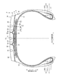
図1は、この発明の実施の形態にかかるプレキュア更生タイヤを示すタイヤ子午線方向の断面図である。同図では、後述するクッションゴム4にハッチングを付してある。なお、符号CLは、タイヤ赤道面である。
[Precure Rehabilitation Tire]
FIG. 1 is a sectional view in the tire meridian direction showing a precure retreaded tire according to an embodiment of the present invention. In the figure, the cushion rubber 4 described later is hatched. Reference sign CL is a tire equator plane.

プレキュア更生タイヤ1は、プレキュアトレッド2と、台タイヤ3とをクッションゴム4で接着して加硫成形したタイヤである。このプレキュア更生タイヤ1は、例えば、トラック、バスなどの重荷重用タイヤに用いられる。   The precure retread tire 1 is a tire obtained by vulcanizing and molding a precure tread 2 and a base tire 3 with a cushion rubber 4. This precure retread tire 1 is used for heavy duty tires such as trucks and buses, for example.

プレキュアトレッド2は、加硫済みのトレッドゴムであり、プレキュア更生タイヤ1のトレッド部を構成する。このプレキュアトレッド2は、板状構造あるいは環状構造を有し、その外周面にプレキュア更生タイヤ1の新品時のトレッドパターンを有する。   The precure tread 2 is a vulcanized tread rubber and constitutes a tread portion of the precure retreaded tire 1. The precure tread 2 has a plate-like structure or an annular structure, and has a tread pattern when the precure retread tire 1 is new on its outer peripheral surface.

台タイヤ3は、残溝が寿命に達したタイヤのトレッドゴムを切除してバフ処理した部材である。   The base tire 3 is a member obtained by cutting out the tread rubber of a tire whose remaining groove has reached the end of its life and buffing it.

クッションゴム4は、シート状の未加硫ゴムであり、プレキュアトレッド2と台タイヤ3との接着に用いられる。   The cushion rubber 4 is a sheet-like unvulcanized rubber and is used for bonding the precure tread 2 and the base tire 3.

また、プレキュア更生タイヤ1は、一般的な構成要素として、一対のビードコア11、11と、一対のビードフィラー12、12と、カーカス層13と、一対の交差ベルトプライ142、143を有するベルト層14と、トレッドゴム15と、左右のサイドウォールゴム16と、左右のリムクッションゴム17、17とを備える。これらの構成要素のうち、トレッドゴム15は、主としてプレキュアトレッド2から成り、他の構成要素は、台タイヤ3に含まれる。   The precure retread tire 1 includes a belt layer 14 having a pair of bead cores 11, 11, a pair of bead fillers 12, 12, a carcass layer 13, and a pair of cross belt plies 142, 143 as general components. And tread rubber 15, left and right sidewall rubbers 16, and left and right rim cushion rubbers 17 and 17. Among these components, the tread rubber 15 is mainly composed of the precure tread 2, and the other components are included in the base tire 3.

また、図1の構成では、ベルト層14が、4枚のベルトプライ141〜144を積層して成り、カーカス層13の外周に掛け廻されて配置される。これらのベルトプライ141〜144は、例えば、高角度ベルト141と、一対の交差ベルト142、143と、ベルトカバー144とから構成される。また、各ベルトプライ141〜144は、スチールあるいは有機繊維材から成る複数のベルトコードをコートゴムで被覆して圧延加工して構成され、所定のベルト角度(タイヤ周方向に対するベルトコードの繊維方向の傾斜角)を有する。   In the configuration of FIG. 1, the belt layer 14 is formed by laminating four belt plies 141 to 144, and is arranged so as to be wound around the outer periphery of the carcass layer 13. These belt plies 141 to 144 include, for example, a high-angle belt 141, a pair of cross belts 142 and 143, and a belt cover 144. Each belt ply 141 to 144 is formed by rolling a plurality of belt cords made of steel or organic fiber material with a coating rubber and rolling the belt cords, and a predetermined belt angle (inclination of the belt cord in the fiber direction with respect to the tire circumferential direction). Corner).

また、プレキュア更生タイヤ1は、タイヤ周方向に延在する複数の周方向主溝21と、これらの周方向主溝21に区画されて成る複数の陸部22とをトレッド面に備える。例えば、図1の構成では、プレキュア更生タイヤ1が、3本の周方向主溝21と、4列の陸部22とを備えている。また、これらの周方向主溝21および陸部22がタイヤ赤道面CLを中心として左右対称に配置されて、左右対称なトレッドパターンが形成されている。なお、各陸部22は、リブであっても良いし、ラグ溝(図示省略)に区画されたブロック列であっても良い。   The precure retread tire 1 includes a plurality of circumferential main grooves 21 extending in the tire circumferential direction and a plurality of land portions 22 defined by the circumferential main grooves 21 on the tread surface. For example, in the configuration of FIG. 1, the precure retreaded tire 1 includes three circumferential main grooves 21 and four rows of land portions 22. Further, the circumferential main grooves 21 and the land portions 22 are arranged symmetrically with respect to the tire equatorial plane CL to form a symmetrical tread pattern. Each land portion 22 may be a rib, or may be a block row partitioned into lug grooves (not shown).

なお、周方向主溝とは、2[mm]以上の溝幅を有する周方向溝をいう。周方向主溝の溝幅は、溝開口部に形成された切欠部や面取部を除外して測定される。   In addition, the circumferential direction main groove means the circumferential direction groove | channel which has a groove width of 2 [mm] or more. The groove width of the circumferential main groove is measured excluding notches and chamfers formed in the groove openings.

[プレキュア更生タイヤの製造方法]
プレキュア更生タイヤ1の製造工程(図示省略)では、プレキュアトレッド2と台タイヤ3とが、クッションゴム4を介して接着される(図1参照)。
[Precured retreaded tire manufacturing method]
In the manufacturing process (not shown) of the precure retread tire 1, the precure tread 2 and the base tire 3 are bonded via the cushion rubber 4 (see FIG. 1).

具体的には、まず、残溝が寿命に達したタイヤのトレッドゴムが切除され、バフ処理が施されて、台タイヤ3が取得される。次に、プレキュアトレッド2の内周面と台タイヤ3の外周面との間にクッションゴム4が挟み込まれ、このクッションゴム4を介してプレキュアトレッド2と台タイヤ3とが接着される。具体的には、クッションゴム4が、台タイヤ3の外周面の全周に渡って貼り付けられ、その後に、プレキュアトレッド2が、台タイヤ3の外周面に配置されてクッションゴム4を介して台タイヤ3に接着される。   Specifically, first, the tread rubber of the tire whose remaining groove has reached the end of its life is cut out, buffed, and the base tire 3 is acquired. Next, the cushion rubber 4 is sandwiched between the inner peripheral surface of the precure tread 2 and the outer peripheral surface of the base tire 3, and the precure tread 2 and the base tire 3 are bonded via the cushion rubber 4. Specifically, the cushion rubber 4 is affixed over the entire outer periphery of the base tire 3, and then the precure tread 2 is disposed on the outer peripheral surface of the base tire 3 and the cushion rubber 4 is interposed therebetween. The base tire 3 is bonded.

このとき、プレキュアトレッド2が板状構造を有する場合には、プレキュアトレッド2が台タイヤ3を一周して巻き付けられて、固定部材(図示省略)により両端部を仮止めして固定される。一方、プレキュアトレッド2が環状構造を有する構成では、プレキュアトレッド2が専用の拡縮径装置(図示省略)により拡径および縮径されて台タイヤ3の外周に嵌め合わされて配置される。   At this time, when the precure tread 2 has a plate-like structure, the precure tread 2 is wound around the base tire 3 and is fixed by temporarily fixing both ends thereof by a fixing member (not shown). . On the other hand, in the configuration in which the precure tread 2 has an annular structure, the precure tread 2 is expanded and contracted by a dedicated expansion / contraction diameter device (not shown) and is fitted to the outer periphery of the base tire 3.

次に、加硫工程が行われる。この加硫工程では、プレキュアトレッド2、台タイヤ3およびクッションゴム4の組立体が加硫缶(図示省略)に収容されて、加硫缶内の空気が真空吸引され、その後に、加熱および加圧が行われて、クッションゴム4が加硫される。その後に、プレキュア更生タイヤ1(図1参照)が加硫缶から取り出される。   Next, a vulcanization process is performed. In this vulcanization process, the assembly of the precure tread 2, the base tire 3 and the cushion rubber 4 is accommodated in a vulcanization can (not shown), the air in the vulcanization can is sucked in vacuum, and then heated and Pressure is applied and the cushion rubber 4 is vulcanized. Thereafter, the precure retread tire 1 (see FIG. 1) is taken out from the vulcanization can.

[プレキュアトレッドと台タイヤとの嵌合構造]
上記のように、プレキュア更生タイヤ1は、プレキュアトレッド2を台タイヤ3に対してクッションゴム4を介して接着して構成される。このとき、タイヤのユニフォミティを向上させるために、プレキュアトレッド2と台タイヤ3との位置決めを精度良く行うべき要請がある。特に、プレキュアトレッド2が板状構造を有する構成では、プレキュアトレッド2の蛇行を抑制するために、プレキュアトレッド2を台タイヤ3に対して精度良く巻き付ける必要がある。
[Fitting structure between precure tread and base tire]
As described above, the precure retread tire 1 is configured by bonding the precure tread 2 to the base tire 3 via the cushion rubber 4. At this time, there is a request that the precure tread 2 and the base tire 3 should be accurately positioned in order to improve the tire uniformity. In particular, in a configuration in which the precure tread 2 has a plate-like structure, it is necessary to wind the precure tread 2 around the base tire 3 with high accuracy in order to suppress meandering of the precure tread 2.

一方で、プレキュア更生タイヤ1では、プレキュアトレッド2とクッションゴム4との間の残存エアが少ないほど、タイヤの耐久性が向上するため、好ましい。   On the other hand, in the precure retreaded tire 1, the smaller the residual air between the precure tread 2 and the cushion rubber 4, the better the durability of the tire.

そこで、このプレキュア更生タイヤ1は、プレキュアトレッド2と台タイヤ3との位置決め精度を向上し、プレキュアトレッド2とクッションゴム4との間の残存エアを低減するために、以下の構成を採用している。   Therefore, this precure retread tire 1 adopts the following configuration in order to improve the positioning accuracy between the precure tread 2 and the base tire 3 and reduce the residual air between the precure tread 2 and the cushion rubber 4. doing.

図2および図3は、図1に記載したプレキュア更生タイヤのトレッド部を示す拡大断面図(図2)および平面図(図3)である。これらの図において、図2は、タイヤ赤道面CLを境界としたトレッド部の片側領域を示している。また、図2では、クッションゴム4にハッチングを付してある。   2 and 3 are an enlarged cross-sectional view (FIG. 2) and a plan view (FIG. 3) showing the tread portion of the precure retread tire described in FIG. In these drawings, FIG. 2 shows one side region of the tread portion with the tire equatorial plane CL as a boundary. In FIG. 2, the cushion rubber 4 is hatched.

このプレキュア更生タイヤ1では、プレキュアトレッド2が、台タイヤ3との接着面に凹部23を有する(図1〜図3参照)。また、台タイヤ3が、プレキュアトレッド2との接着面に凸部31を有する。また、プレキュアトレッド2の凹部23と台タイヤ3の凸部31とが、相互に嵌合する形状を有する。   In this precure retread tire 1, the precure tread 2 has the recessed part 23 in the adhesive surface with the base tire 3 (refer FIGS. 1-3). Further, the base tire 3 has a convex portion 31 on the adhesive surface with the precure tread 2. Moreover, the recessed part 23 of the precure tread 2 and the convex part 31 of the base tire 3 have a shape which mutually fits.

例えば、図1〜図3の構成では、プレキュアトレッド2が、その内周面に2つの凹部23、23を有している。また、これらの凹部23が、タイヤ赤道面CLを境界として左右対称に配置されている。また、各凹部23が、タイヤ幅方向の最も外側にある周方向主溝(最外周方向主溝)22よりもタイヤ幅方向内側に配置されている。また、凹部23が、タイヤ周方向に連続する環状溝であり、タイヤ全周に渡って延在している。また、台タイヤ3が、左右一対の凸部31、31を有し、これらの凸部31、31が、プレキュアトレッド2の各凹部23に対応する位置に配置されている。また、凸部31が、タイヤ周方向に連続する環状のリブであり、タイヤ全周に渡って延在している。これにより、2組の凹部23および凸部31が、タイヤ幅方向に配置されている。また、各組の凹部23および凸部31が、同一形状(図2では、円弧形状)を有することにより相互に嵌合可能に構成されている。   For example, in the configuration of FIGS. 1 to 3, the precure tread 2 has two recesses 23, 23 on its inner peripheral surface. Moreover, these recessed parts 23 are arrange | positioned left-right symmetrically for the tire equator surface CL as a boundary. Moreover, each recessed part 23 is arrange | positioned in the tire width direction inner side rather than the circumferential main groove (outermost peripheral direction main groove) 22 in the outermost side of a tire width direction. Moreover, the recessed part 23 is an annular groove continuous in the tire circumferential direction, and extends over the entire circumference of the tire. Further, the base tire 3 has a pair of left and right convex portions 31, 31, and these convex portions 31, 31 are arranged at positions corresponding to the respective concave portions 23 of the precure tread 2. Moreover, the convex part 31 is an annular rib continuous in the tire circumferential direction, and extends over the entire tire circumference. Thereby, two sets of crevice 23 and convex part 31 are arranged in the tire width direction. In addition, the concave portions 23 and the convex portions 31 of each set have the same shape (arc shape in FIG. 2) so that they can be fitted to each other.

また、このプレキュア更生タイヤ1では、プレキュアトレッド2が、凹部23からトレッド踏面に貫通する貫通孔24を有する(図1〜図3参照)。また、少なくとも1つの貫通孔24が、プレキュアトレッド2をタイヤ周方向に8等分した各領域にそれぞれ配置されることが好ましい。   Moreover, in this precure retread tire 1, the precure tread 2 has the through-hole 24 which penetrates from the recessed part 23 to a tread surface (refer FIGS. 1-3). Moreover, it is preferable that at least one through hole 24 is disposed in each region obtained by dividing the precure tread 2 into eight equal parts in the tire circumferential direction.

例えば、図1〜図3の構成では、貫通孔24が、プレキュアトレッド2をプレキュアトレッド2の肉厚方向に貫通して、陸部22の踏面と凹部23の最深部とに開口している。また、1つの凹部23に対して複数の貫通孔24がそれぞれ設けられ、これらの貫通孔24が、タイヤ周方向に所定間隔で配置されている。   For example, in the configuration of FIGS. 1 to 3, the through hole 24 penetrates the precure tread 2 in the thickness direction of the precure tread 2 and opens to the tread surface of the land portion 22 and the deepest portion of the recess 23. Yes. Further, a plurality of through holes 24 are provided for each recess 23, and these through holes 24 are arranged at predetermined intervals in the tire circumferential direction.

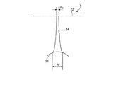
図4は、図1に記載したプレキュア更生タイヤのプレキュアトレッドの凹部を示す説明図である。図5は、図1に記載したプレキュア更生タイヤの台タイヤの凸部を示す説明図である。これらの図において、図4は、部品時におけるプレキュアトレッド2の凹部23および貫通孔24を示し、また、図5は、部品時における台タイヤ3の凸部31を示している。   FIG. 4 is an explanatory view showing a concave portion of the precure tread of the precure retread tire described in FIG. 1. FIG. 5 is an explanatory view showing a convex portion of a base tire of the precure retread tire described in FIG. 1. In these drawings, FIG. 4 shows the concave portion 23 and the through hole 24 of the precure tread 2 at the time of components, and FIG. 5 shows the convex portion 31 of the base tire 3 at the time of components.

図1〜図3の構成では、図4に示すように、プレキュアトレッド2の凹部23および貫通孔24が、周方向主溝21に対してタイヤ幅方向に相互に位置をずらして配置されている。具体的には、陸部22のエッジ部から陸部22の踏面に対する垂線を引いたときに、凹部23および貫通孔24が、この垂線よりも陸部22の内部側に配置されている。このため、貫通孔24が、陸部22の踏面に開口している。   In the configuration of FIGS. 1 to 3, as shown in FIG. 4, the concave portion 23 and the through hole 24 of the precure tread 2 are arranged so as to be shifted from each other in the tire width direction with respect to the circumferential main groove 21. Yes. Specifically, when a perpendicular to the tread surface of the land portion 22 is drawn from the edge portion of the land portion 22, the recess 23 and the through hole 24 are disposed on the inner side of the land portion 22 than the perpendicular. For this reason, the through hole 24 is opened in the tread surface of the land portion 22.

また、凹部23の開口幅Wおよび深さDが、3[mm]≦W≦25[mm]および1[mm]≦D≦5[mm]の範囲内にあることが好ましく、5[mm]≦W≦15[mm]および2[mm]≦D≦4[mm]の範囲内にあることがより好ましい(図4参照)。また、凹部23の開口幅Wおよび深さDが、0.1≦D/W≦0.8の関係を有することが好ましい。なお、凹部23の開口幅Wは、タイヤ子午線方向の断面視にて測定される。   The opening width W and depth D of the recess 23 are preferably in the ranges of 3 [mm] ≦ W ≦ 25 [mm] and 1 [mm] ≦ D ≦ 5 [mm], and 5 [mm]. More preferably, they are within the ranges of ≦ W ≦ 15 [mm] and 2 [mm] ≦ D ≦ 4 [mm] (see FIG. 4). Moreover, it is preferable that the opening width W and the depth D of the recessed part 23 have a relationship of 0.1 ≦ D / W ≦ 0.8. The opening width W of the recess 23 is measured by a cross-sectional view in the tire meridian direction.

また、凹部23が、プレキュアトレッド2の内周面からトレッド踏面に向かうに連れて、その断面積を狭めることが好ましい(図4参照)。例えば、図4の構成では、タイヤ子午線方向の断面視にて、凹部23が円弧形状を有することにより、開口部から底部に向かって幅を狭めている。   Moreover, it is preferable that the cross-sectional area becomes narrow as the recessed part 23 goes to the tread surface from the inner peripheral surface of the precure tread 2 (refer FIG. 4). For example, in the configuration of FIG. 4, the recess 23 has an arc shape in a cross-sectional view in the tire meridian direction, so that the width is narrowed from the opening toward the bottom.

また、凹部23に対する貫通孔24の開口幅Riが、1[mm]≦Ri≦8[mm]の範囲内にあることが好ましく、2[mm]≦Ri≦4[mm]の範囲内にあることがより好ましい(図4参照)。また、トレッド踏面に対する貫通孔24の開口幅Roが、凹部23に対する貫通孔24の開口幅Riに対して、0[mm]≦Ri−Ro≦4[mm]の関係を有することが好ましい。貫通孔24の開口幅Ri、Roは、タイヤ子午線方向の断面視にて測定される。   The opening width Ri of the through-hole 24 with respect to the recess 23 is preferably in the range of 1 [mm] ≦ Ri ≦ 8 [mm], and preferably in the range of 2 [mm] ≦ Ri ≦ 4 [mm]. More preferably (see FIG. 4). Further, it is preferable that the opening width Ro of the through hole 24 with respect to the tread surface has a relationship of 0 [mm] ≦ Ri−Ro ≦ 4 [mm] with respect to the opening width Ri of the through hole 24 with respect to the recess 23. The opening widths Ri and Ro of the through holes 24 are measured in a sectional view in the tire meridian direction.

さらに、貫通孔24が、凹部23からトレッド踏面に向かうに連れて、その断面積を狭めることが好ましい。例えば、図4の構成では、貫通孔24の開口幅が、凹部23からトレッド踏面に向かうに連れて単調減少している。   Furthermore, it is preferable that the cross-sectional area of the through hole 24 is narrowed as it goes from the recess 23 toward the tread surface. For example, in the configuration of FIG. 4, the opening width of the through hole 24 monotonously decreases from the recess 23 toward the tread surface.

また、タイヤ子午線方向の断面視における凹部23の断面積Sdと、貫通孔24の断面積Spとが、0.1≦Sd/Sp≦1.0の関係を有することが好ましく、0.3≦Sd/Sp≦0.7の関係を有することがより好ましい。凹部23の断面積Sdおよび貫通孔24の断面積Spは、タイヤ子午線方向の断面視にて測定される。また、凹部23と貫通孔24とは、凹部23の底面の延長面を境界として区画される。   Moreover, it is preferable that the cross-sectional area Sd of the recess 23 in the cross-sectional view in the tire meridian direction and the cross-sectional area Sp of the through hole 24 have a relationship of 0.1 ≦ Sd / Sp ≦ 1.0, and 0.3 ≦ It is more preferable to have a relationship of Sd / Sp ≦ 0.7. The cross-sectional area Sd of the recess 23 and the cross-sectional area Sp of the through hole 24 are measured in a cross-sectional view in the tire meridian direction. Further, the recess 23 and the through hole 24 are partitioned with an extended surface of the bottom surface of the recess 23 as a boundary.

また、クッションゴム4のゲージGa(図示省略)が、0.8[mm]≦Ga≦2.0[mm]の範囲内にあることが好ましい。ただし、クッションゴム4のゲージGaは、タイヤ幅方向に均一でなくとも良く、例えば、クッションゴム4が部分的に多層構造を有する等により、クッションゴム4が凹凸を有しても良い(図示省略)。   The gauge Ga (not shown) of the cushion rubber 4 is preferably in the range of 0.8 [mm] ≦ Ga ≦ 2.0 [mm]. However, the gauge Ga of the cushion rubber 4 does not have to be uniform in the tire width direction. For example, the cushion rubber 4 may have unevenness due to the cushion rubber 4 partially having a multilayer structure (not shown). ).

また、プレキュアトレッド2の凹部23と、台タイヤ3の凸部31とが相互に嵌合可能な形状を有することが好ましい。嵌合とは、プレキュアトレッド2と台タイヤ3とがクッションゴム4を挟み込んで組み立てられたときに、凹部23と凸部31とがクッションゴム4を介して噛み合うことをいう。これにより、プレキュアトレッド2と台タイヤ3とを適正に位置決めできる。   Moreover, it is preferable that the recessed part 23 of the precure tread 2 and the convex part 31 of the base tire 3 have a shape which can be mutually fitted. The fitting means that the concave portion 23 and the convex portion 31 are engaged with each other via the cushion rubber 4 when the precure tread 2 and the base tire 3 are assembled with the cushion rubber 4 interposed therebetween. Thereby, the precure tread 2 and the base tire 3 can be positioned appropriately.

例えば、図4および図5の構成では、タイヤ子午線方向の断面視にて、凹部23と凸部31とが相似かつ円弧状の断面形状を有している。また、凹部23の開口幅Wおよび深さDと、凸部31の開口幅W’および深さD’と、クッションゴム4のゲージGaとが、0[mm]≦W−W’−Ga≦1.0[mm]かつ0[mm]≦D−D’−Ga≦1.0[mm]の関係に設定されている。   For example, in the configurations of FIGS. 4 and 5, the concave portion 23 and the convex portion 31 have a similar and arcuate cross-sectional shape in a cross-sectional view in the tire meridian direction. The opening width W and depth D of the recess 23, the opening width W ′ and depth D ′ of the protrusion 31, and the gauge Ga of the cushion rubber 4 are 0 [mm] ≦ W−W′−Ga ≦. The relationship is set to 1.0 [mm] and 0 [mm] ≦ DD′−Ga ≦ 1.0 [mm].

なお、上記した凹部23の開口幅W、深さDおよび断面積Sd、貫通孔24の開口幅Ri、Roおよび断面積Sp、ならびに、クッションゴム4のゲージGaは、タイヤを規定リムに装着して規定内圧を付与すると共に無負荷状態として測定される。   The opening width W, depth D and cross-sectional area Sd of the recess 23, the opening width Ri and Ro and cross-sectional area Sp of the through hole 24, and the gauge Ga of the cushion rubber 4 attach the tire to the specified rim. The specified internal pressure is applied and the load is measured as no load.

なお、規定リムとは、JATMAに規定される「適用リム」、TRAに規定される「Design Rim」、あるいはETRTOに規定される「Measuring Rim」をいう。また、規定内圧とは、JATMAに規定される「最高空気圧」、TRAに規定される「TIRE LOAD LIMITS AT VARIOUS COLD INFLATION PRESSURES」の最大値、あるいはETRTOに規定される「INFLATION PRESSURES」をいう。また、規定荷重とは、JATMAに規定される「最大負荷能力」、TRAに規定される「TIRE LOAD LIMITS AT VARIOUS COLD INFLATION PRESSURES」の最大値、あるいはETRTOに規定される「LOAD CAPACITY」をいう。ただし、JATMAにおいて、乗用車用タイヤの場合には、規定内圧が空気圧180[kPa]であり、規定荷重が最大負荷能力の88[%]である。   The specified rim refers to “applied rim” defined in JATMA, “Design Rim” defined in TRA, or “Measuring Rim” defined in ETRTO. The specified internal pressure means “maximum air pressure” defined by JATMA, the maximum value of “TIRE LOAD LIMITS AT VARIOUS COLD INFLATION PRESSURES” defined by TRA, or “INFLATION PRESSURES” defined by ETRTO. The specified load means the “maximum load capacity” defined by JATMA, the maximum value of “TIRE LOAD LIMITS AT VARIOUS COLD INFLATION PRESSURES” defined by TRA, or “LOAD CAPACITY” defined by ETRTO. However, in JATMA, in the case of tires for passenger cars, the specified internal pressure is air pressure 180 [kPa], and the specified load is 88 [%] of the maximum load capacity.

図6は、図1に記載したプレキュア更生タイヤの製造工程を示す説明図である。同図は、プレキュアトレッド2、台タイヤ3およびクッションゴム4の組立工程を概念的に示している。   FIG. 6 is an explanatory diagram illustrating a manufacturing process of the precure retread tire described in FIG. 1. The figure conceptually shows the assembly process of the precure tread 2, the base tire 3, and the cushion rubber 4.

プレキュア更生タイヤ1の製造工程では、上記のように、プレキュアトレッド2の内周面と台タイヤ3の外周面との間にクッションゴム4が挟み込まれ、このクッションゴム4を介してをプレキュアトレッド2と台タイヤ3とが接着される(図6参照)。このとき、プレキュアトレッド2の凹部23と台タイヤ3の凸部31とが、クッションゴム4を介して相互に嵌合する(図1および図2参照)。これにより、プレキュアトレッド2と台タイヤ3との位置決めが精度良く行われる。   In the manufacturing process of the precure retread tire 1, as described above, the cushion rubber 4 is sandwiched between the inner peripheral surface of the precure tread 2 and the outer peripheral surface of the base tire 3, and the precure is passed through the cushion rubber 4. The tread 2 and the base tire 3 are bonded (see FIG. 6). At this time, the concave portion 23 of the precure tread 2 and the convex portion 31 of the base tire 3 are fitted to each other via the cushion rubber 4 (see FIGS. 1 and 2). Thereby, positioning with the precure tread 2 and the base tire 3 is performed with sufficient precision.

また、加硫工程では、上記のように、プレキュアトレッド2、台タイヤ3およびクッションゴム4の組立体が加硫缶に収容されて、加硫缶内の空気が真空吸引される(図示省略)。このため、プレキュアトレッド2の凹部23と台タイヤ3の凸部31との間にある残留エアが、プレキュアトレッド2の貫通孔24を介してタイヤ外部に吸い出される。また、クッションゴム4が、貫通孔24に流入して貫通孔24を塞ぐ(図2参照)。これにより、タイヤ内部の残留エアが除去され、また、貫通孔24がクッションゴム4により封止されてタイヤ内部への水分の浸入経路が遮断される。   Further, in the vulcanization process, as described above, the assembly of the precure tread 2, the base tire 3 and the cushion rubber 4 is accommodated in the vulcanization can, and the air in the vulcanization can is sucked in vacuum (not shown). ). For this reason, residual air between the concave portion 23 of the precure tread 2 and the convex portion 31 of the base tire 3 is sucked out of the tire through the through hole 24 of the precure tread 2. Further, the cushion rubber 4 flows into the through hole 24 and closes the through hole 24 (see FIG. 2). As a result, residual air inside the tire is removed, and the through hole 24 is sealed by the cushion rubber 4 to block the water ingress path into the tire.

図7〜図11は、図1に記載したプレキュア更生タイヤの変形例を示す説明図である。これらの図は、プレキュアトレッド2の要部の拡大断面図を示している。   7-11 is explanatory drawing which shows the modification of the precure retreaded tire described in FIG. These drawings show enlarged cross-sectional views of the main part of the precure tread 2.

図1の構成では、上記のように、プレキュアトレッド2の凹部23が、タイヤ子午線方向の断面視にて円弧形状を有している(図4参照)。   In the configuration of FIG. 1, as described above, the recess 23 of the precure tread 2 has an arc shape in a sectional view in the tire meridian direction (see FIG. 4).

しかし、これに限らず、凹部23が、例えば、タイヤ子午線方向の断面視にて三角形状、台形状、楕円形状、矩形状、これらを組み合わせた形状などを有しても良い。このとき、図7に示すように、凹部23が、深さ方向に向かうに連れて断面積を狭める形状を有することが好ましい。さらに、図8に示すように、凹部23が、開口縁部および底縁部にR形状を有することが好ましい。また、台タイヤ3の凸部31も、かかるプレキュアトレッド2の凹部23に対応する形状を有することが好ましい。これらにより、プレキュアトレッド2と台タイヤ3との組立状態にて、クッションゴム4が凹部23の内周面および凸部31の外周面に密着できるので、タイヤ内部の残留エアが低減される。   However, the present invention is not limited to this, and the recess 23 may have, for example, a triangular shape, a trapezoidal shape, an elliptical shape, a rectangular shape, or a combination thereof in a sectional view in the tire meridian direction. At this time, as shown in FIG. 7, it is preferable that the recessed part 23 has a shape which narrows a cross-sectional area as it goes to the depth direction. Furthermore, as shown in FIG. 8, it is preferable that the recessed part 23 has R shape in an opening edge part and a bottom edge part. Moreover, it is preferable that the convex part 31 of the base tire 3 also has a shape corresponding to the concave part 23 of the precure tread 2. As a result, in the assembled state of the precure tread 2 and the base tire 3, the cushion rubber 4 can be in close contact with the inner peripheral surface of the concave portion 23 and the outer peripheral surface of the convex portion 31, so that residual air inside the tire is reduced.

また、図1の構成では、貫通孔24が、プレキュアトレッド2の凹部23からトレッド踏面に向かって径を狭める形状(Ri→Ro)を有している(図4参照)。このとき、貫通孔24が、タイヤ子午線方向の断面視にて直線となる壁面形状を有している。   Further, in the configuration of FIG. 1, the through hole 24 has a shape (Ri → Ro) whose diameter decreases from the recess 23 of the precure tread 2 toward the tread surface (see FIG. 4). At this time, the through hole 24 has a wall surface shape that is a straight line in a sectional view in the tire meridian direction.

しかし、これに限らず、図9に示すように、貫通孔24がプレキュアトレッド2の凹部23からトレッド踏面に向かって径を狭める形状において、貫通孔24の断面積の減少量が凹部23側にて小さくトレッド踏面側にて大きくなるように構成されても良い。このように、貫通孔24が、トレッド踏面側(クッションゴム4の出口側)にて断面積を急に狭めることにより、加硫工程にて、クッションゴム4が貫通孔24を隙間なく塞ぎ得る。   However, the present invention is not limited to this, and as shown in FIG. 9, when the through hole 24 has a shape whose diameter decreases from the concave portion 23 of the precure tread 2 toward the tread surface, the amount of reduction in the cross-sectional area of the through hole 24 is on the concave portion 23 side. It may be configured to be small and large on the tread surface side. As described above, the through hole 24 abruptly narrows the cross-sectional area on the tread tread surface side (the exit side of the cushion rubber 4), so that the cushion rubber 4 can block the through hole 24 without a gap in the vulcanization process.

また、図10に示すように、貫通孔24がプレキュアトレッド2の凹部23からトレッド踏面に向かって径を狭める形状において、貫通孔24の断面積の減少量が凹部23側にて大きくトレッド踏面側にて小さくなるように構成されても良い。このように、貫通孔24が、凹部23側(クッションゴム4の入口側)にて断面積を広げることにより、加硫工程にて、クッションゴム4が貫通孔24に流入し易くなる。   Further, as shown in FIG. 10, when the through hole 24 has a shape in which the diameter narrows from the concave portion 23 of the precure tread 2 toward the tread surface, the amount of reduction in the cross-sectional area of the through hole 24 greatly increases on the concave portion 23 side. You may comprise so that it may become small on the side. As described above, the through-hole 24 increases the cross-sectional area on the recess 23 side (the entrance side of the cushion rubber 4), so that the cushion rubber 4 easily flows into the through-hole 24 in the vulcanization process.

また、図1の構成では、貫通孔24が、軸方向に垂直な断面視(トレッド平面視)にて円形状を有している(図3参照)。また、タイヤ周方向に隣り合う貫通孔24、32が、相互に分離している。   In the configuration of FIG. 1, the through hole 24 has a circular shape in a cross-sectional view (tread plan view) perpendicular to the axial direction (see FIG. 3). Moreover, the through holes 24 and 32 adjacent to each other in the tire circumferential direction are separated from each other.

しかし、これに限らず、貫通孔24が、例えば、軸方向に垂直な断面視にて楕円形状を有しても良いし、長尺なスリット形状を有しても良い(図示省略)。また、隣り合う貫通孔24、32がスリットなどを介して相互に連結されても良い(図示省略)。また、これらの構成において、貫通孔24の開口部がR形状の隅部を有することにより、この隅部における残留エアが低減される。   However, the present invention is not limited to this, and the through hole 24 may have, for example, an elliptical shape in a cross-sectional view perpendicular to the axial direction, or may have a long slit shape (not shown). Further, the adjacent through holes 24 and 32 may be connected to each other through a slit or the like (not shown). Moreover, in these structures, since the opening part of the through-hole 24 has an R-shaped corner part, the residual air in this corner part is reduced.

また、図1の構成では、上記のように、プレキュアトレッド2の凹部23が、タイヤ周方向に延在する環状溝であり、タイヤ周方向に一周している(図2参照)。また、台タイヤ3の凸部31が、タイヤ周方向に延在する環状のリブであり、タイヤ周方向に一周している(図示省略)。そして、プレキュアトレッド2の凹部23と台タイヤ3の凸部31とがタイヤ全周にて嵌合している。かかる構成は、プレキュアトレッド2に対する凹部23の加工成形および台タイヤ3に対する凸部31の加工成形が容易であり、また、プレキュアトレッド2を台タイヤ3に貼り付けるときに凹部23と凸部31とを容易に嵌め合わせ得る点で好ましい。   Moreover, in the structure of FIG. 1, as mentioned above, the recessed part 23 of the precure tread 2 is an annular groove extended in a tire circumferential direction, and makes one round in a tire circumferential direction (refer FIG. 2). Further, the convex portion 31 of the base tire 3 is an annular rib extending in the tire circumferential direction, and makes a round in the tire circumferential direction (not shown). And the recessed part 23 of the precure tread 2 and the convex part 31 of the base tire 3 are fitted in the tire perimeter. Such a configuration facilitates the processing and molding of the concave portion 23 with respect to the precure tread 2 and the processing and molding of the convex portion 31 with respect to the base tire 3, and the concave portion 23 and the convex portion when the precure tread 2 is attached to the base tire 3. 31 is preferable in that it can be easily fitted.

しかし、これに限らず、凹部23および凸部31が、タイヤ周方向に分断された構造を有しても良い(図示省略)。例えば、相互に噛み合う半球形状あるいはブロック形状を有する複数組の凹部23および凸部31が、タイヤ周方向に所定間隔で点在して配置されても良い(図示省略)。   However, the present invention is not limited to this, and the concave portion 23 and the convex portion 31 may have a structure divided in the tire circumferential direction (not shown). For example, a plurality of sets of concave portions 23 and convex portions 31 having a hemispherical shape or a block shape that mesh with each other may be arranged at predetermined intervals in the tire circumferential direction (not shown).

また、図1の構成では、上記のように、プレキュアトレッド2が2つの凹部23、23を有し、これらの凹部23が、タイヤ赤道面CLを境界として左右対称に配置されている(図1および図3参照)。   In the configuration of FIG. 1, as described above, the precure tread 2 has two recesses 23, 23, and these recesses 23 are arranged symmetrically with respect to the tire equatorial plane CL (see FIG. 1). 1 and FIG. 3).

しかし、これに限らず、プレキュアトレッド2が、単一の凹部23を有しても良いし、3つ以上の凹部23を有しても良い。例えば、単一の凹部23が、タイヤ赤道面CL上に配置されても良いし、複数の凹部23がタイヤ幅方向の所定の位置に配置されても良い(図示省略)。このとき、タイヤ幅方向に配置される凹部23の数が、5つ以下であることが好ましい。また、上記の構成では、台タイヤ3が、プレキュアトレッド2の各凹部23に対応する凸部31をそれぞれ有する。   However, the present invention is not limited to this, and the precure tread 2 may have a single recess 23 or may have three or more recesses 23. For example, the single recessed part 23 may be arrange | positioned on the tire equator surface CL, and the several recessed part 23 may be arrange | positioned in the predetermined position of a tire width direction (illustration omitted). At this time, it is preferable that the number of the recessed parts 23 arrange | positioned at a tire width direction is five or less. Further, in the above configuration, the base tire 3 has the convex portions 31 corresponding to the respective concave portions 23 of the precure tread 2.

また、図1の構成では、プレキュアトレッド2および台タイヤ3が左右一組の凹部23および凸部31を有している。   In the configuration of FIG. 1, the precure tread 2 and the base tire 3 have a pair of left and right concave portions 23 and convex portions 31.

しかし、これに限らず、プレキュアトレッド2および台タイヤ3が3組以上の凹部23および凸部31を有しても良い。このとき、図11に示すように、タイヤ幅方向に隣り合う凹部23、23のうちタイヤ赤道面CL側にある凹部23の深さD_ceおよび幅W_ceと、ショルダー部側にある凹部23の深さD_shおよび幅W_ceとが、D_sh≦D_ceおよびW_sh≦W_ceの関係を有する。このとき、0.9≦D_ce/D_shおよび0.9≦W_ce/W_shの関係を有することが好ましい。すなわち、同等以上の大きさを有する(好ましくは、より大きい)凹部23が、タイヤ赤道面CL側に配置されることが好ましい。   However, the present invention is not limited to this, and the precure tread 2 and the base tire 3 may have three or more sets of concave portions 23 and convex portions 31. At this time, as shown in FIG. 11, the depth D_ce and the width W_ce of the recess 23 on the tire equatorial plane CL side among the recesses 23 and 23 adjacent in the tire width direction, and the depth of the recess 23 on the shoulder side. D_sh and width W_ce have a relationship of D_sh ≦ D_ce and W_sh ≦ W_ce. At this time, it is preferable to have a relationship of 0.9 ≦ D_ce / D_sh and 0.9 ≦ W_ce / W_sh. That is, it is preferable that the recess 23 having a size equal to or greater than (preferably larger) is disposed on the tire equatorial plane CL side.

[効果]
以上説明したように、このプレキュア更生タイヤ1は、プレキュアトレッド2と、台タイヤ3と、プレキュアトレッド2および台タイヤ3を接着するクッションゴム4とを備える(図1および図2参照)。また、プレキュア更生タイヤ1は、タイヤ周方向に延在する複数の周方向主溝21と、周方向主溝21に区画されて成る複数の陸部22とをトレッド面に備える。また、プレキュアトレッド2が、台タイヤ3との接着面に形成される凹部23と、凹部23から陸部22の踏面に貫通する貫通孔24とを有する。また、台タイヤ3が、クッションゴム4を介して凹部23に嵌合する凸部31を有する。
[effect]
As described above, the precure retread tire 1 includes the precure tread 2, the base tire 3, and the cushion rubber 4 that bonds the precure tread 2 and the base tire 3 (see FIGS. 1 and 2). The precure retread tire 1 includes a plurality of circumferential main grooves 21 extending in the tire circumferential direction and a plurality of land portions 22 defined by the circumferential main grooves 21 on the tread surface. Further, the precure tread 2 has a recess 23 formed on the adhesion surface with the base tire 3 and a through hole 24 penetrating from the recess 23 to the tread surface of the land portion 22. Further, the base tire 3 has a convex portion 31 that fits into the concave portion 23 via the cushion rubber 4.

かかる構成では、プレキュアトレッド2、台タイヤ3およびクッションゴム4の組立工程にて、プレキュアトレッド2の凹部23と台タイヤ3の凸部31とが、クッションゴム4を挟み込みつつ相互に嵌合する(図1および図2参照)。これにより、プレキュアトレッド2と台タイヤ3との位置決めを簡易かつ精度良く行い得るので、タイヤのユニフォミティが向上する利点がある。また、加硫工程では、プレキュアトレッド2の凹部23と台タイヤ3の凸部31との間にある残留エアがプレキュアトレッド2の貫通孔24を介してタイヤ外部に吸い出されて、タイヤ内部の残留エアが除去される。また、クッションゴム4が、貫通孔24に流入して貫通孔24を塞ぐことにより、貫通孔24がクッションゴム4により封止されて、タイヤ内部への水分の浸入経路が遮断される(図2参照)。これらにより、タイヤの耐久性能が向上する利点がある。   In this configuration, in the assembly process of the precure tread 2, the base tire 3 and the cushion rubber 4, the concave portion 23 of the precure tread 2 and the convex portion 31 of the base tire 3 are fitted together while sandwiching the cushion rubber 4. (See FIGS. 1 and 2). Thereby, since the positioning of the precure tread 2 and the base tire 3 can be performed easily and accurately, there is an advantage that the uniformity of the tire is improved. Further, in the vulcanization process, residual air between the concave portion 23 of the precure tread 2 and the convex portion 31 of the base tire 3 is sucked out of the tire through the through hole 24 of the precure tread 2, and the tire Internal residual air is removed. Further, the cushion rubber 4 flows into the through-hole 24 and closes the through-hole 24, whereby the through-hole 24 is sealed by the cushion rubber 4 and the water intrusion path into the tire is blocked (FIG. 2). reference). By these, there exists an advantage which the durable performance of a tire improves.

また、このプレキュア更生タイヤ1では、プレキュアトレッド2の凹部23が、タイヤ周方向に連続する環状溝であり(図3参照)、凸部31が、タイヤ周方向に連続するリブである。かかる構成では、凹部23および凸部31の加工成形が容易であり、また、台タイヤ3およびクッションゴム4の組立工程にて、プレキュアトレッド2が台タイヤ3に対して蛇行して設置される事態を効果的に抑制できる利点がある。   Further, in the precure retread tire 1, the recess 23 of the precure tread 2 is an annular groove continuous in the tire circumferential direction (see FIG. 3), and the convex portion 31 is a rib continuous in the tire circumferential direction. In such a configuration, the concave and convex portions 23 and the convex portions 31 can be easily processed and formed, and the precure tread 2 is installed meandering with respect to the base tire 3 in the assembly process of the base tire 3 and the cushion rubber 4. There is an advantage that the situation can be effectively suppressed.

また、このプレキュア更生タイヤ1では、プレキュアトレッド2の貫通孔24が、凹部23の最深部に開口する(図4参照)。これにより、加硫工程にて、凹部23内の残留エアが貫通孔24を介して排出され易くなり、また、クッションゴム4が凹部23から貫通孔24に流入し易くなる利点がある。   Moreover, in this precure retread tire 1, the through-hole 24 of the precure tread 2 opens in the deepest part of the recessed part 23 (refer FIG. 4). Thereby, in the vulcanization process, there is an advantage that the residual air in the recess 23 is easily discharged through the through hole 24, and the cushion rubber 4 easily flows into the through hole 24 from the recess 23.

また、このプレキュア更生タイヤ1では、凹部23が、凹部23の深さ方向に向かうに連れて断面積を狭める(図4参照)。これにより、加硫工程にて、凹部23内の残留エアが貫通孔24を介して排出され易くなる利点がある。   Moreover, in this precure retreaded tire 1, the recessed part 23 narrows a cross-sectional area as it goes to the depth direction of the recessed part 23 (refer FIG. 4). Accordingly, there is an advantage that residual air in the recess 23 is easily discharged through the through hole 24 in the vulcanization process.

また、このプレキュア更生タイヤ1では、貫通孔24が、凹部23から陸部22の踏面に向かうに連れて断面積を狭める(図4参照)。これにより、加硫工程にて、クッションゴム4が貫通孔24を適正に塞いで封止する利点がある。   Moreover, in this precure retreaded tire 1, the through-hole 24 narrows a cross-sectional area as it goes to the tread of the land part 22 from the recessed part 23 (refer FIG. 4). Accordingly, there is an advantage that the cushion rubber 4 appropriately closes and seals the through hole 24 in the vulcanization process.

また、このプレキュア更生タイヤ1では、凹部23の開口幅Wおよび深さDが、3[mm]≦W≦25[mm]および1[mm]≦D≦5[mm]の範囲内にある(図4参照)。これにより、凹部23の開口幅Wおよび深さDが適正化される利点がある。すなわち、3[mm]≦Wおよび1[mm]≦Dであることにより、プレキュアトレッド2と台タイヤ3の組立工程にて、凹部23と凸部31とを容易に嵌め合わせ得る。また、W≦25[mm]およびD≦5[mm]であることにより、加硫工程にて、凹部23内の残留エアが貫通孔24を介して排出され易くなる。   Moreover, in this precure retread tire 1, the opening width W and depth D of the recessed part 23 exist in the range of 3 [mm] <= W <= 25 [mm] and 1 [mm] <= D <= 5 [mm] ( (See FIG. 4). Thereby, there exists an advantage by which the opening width W and the depth D of the recessed part 23 are optimized. That is, by satisfying 3 [mm] ≦ W and 1 [mm] ≦ D, the concave portion 23 and the convex portion 31 can be easily fitted in the assembly process of the precure tread 2 and the base tire 3. Further, since W ≦ 25 [mm] and D ≦ 5 [mm], residual air in the recess 23 is easily discharged through the through hole 24 in the vulcanization step.

また、このプレキュア更生タイヤ1では、プレキュアトレッド2が、複数の凹部23を有し、且つ、タイヤ幅方向に隣り合う一対の凹部23のうちタイヤ赤道面CL側にある凹部23の深さD_ceと、ショルダー部側にある凹部23の深さD_shとが、D_sh≦D_ceの関係を有する(図11参照)。これにより、プレキュアトレッド2と台タイヤ3の組立工程にて、凹部23と凸部31とを容易に嵌め合わせ得る利点がある。   Further, in this precure retread tire 1, the precure tread 2 has a plurality of recesses 23, and the depth D_ce of the recesses 23 on the tire equatorial plane CL side of the pair of recesses 23 adjacent in the tire width direction. And the depth D_sh of the recess 23 on the shoulder side has a relationship of D_sh ≦ D_ce (see FIG. 11). Thereby, there exists an advantage which can fit the recessed part 23 and the convex part 31 in the assembly process of the precure tread 2 and the base tire 3 easily.

また、このプレキュア更生タイヤ1では、プレキュアトレッド2が、複数の凹部23を有し、且つ、タイヤ幅方向に隣り合う一対の凹部23のうちタイヤ赤道面CL側にある凹部23の幅W_ceと、ショルダー部側にある凹部23の幅W_shとが、W_sh≦W_ceの関係を有する(図11参照)。これにより、プレキュアトレッド2と台タイヤ3の組立工程にて、凹部23と凸部31とを容易に嵌め合わせ得る利点がある。   Further, in the precure retread tire 1, the precure tread 2 has a plurality of recesses 23, and the width W_ce of the recesses 23 on the tire equatorial plane CL side of the pair of recesses 23 adjacent in the tire width direction. The width W_sh of the recess 23 on the shoulder portion side has a relationship of W_sh ≦ W_ce (see FIG. 11). Thereby, there exists an advantage which can fit the recessed part 23 and the convex part 31 in the assembly process of the precure tread 2 and the base tire 3 easily.

また、このプレキュア更生タイヤ1では、凹部23に対する貫通孔24の開口幅Riが、1[mm]≦Ri≦8[mm]の範囲内にある(図4参照)。これにより、貫通孔24の開口幅Riが適正化される利点がある。すなわち、1[mm]≦Riであることにより、加硫工程にて、凹部23内の残留エアが貫通孔24を介して排出され易くなる。また、Ri≦8[mm]であることにより、加硫工程にて、クッションゴム4が貫通孔24を適正に塞いで封止する。   Moreover, in this precure retreaded tire 1, the opening width Ri of the through-hole 24 with respect to the recessed part 23 exists in the range of 1 [mm] <= Ri <= 8 [mm] (refer FIG. 4). Thereby, there exists an advantage by which the opening width Ri of the through-hole 24 is optimized. That is, when 1 [mm] ≦ Ri, residual air in the recess 23 is easily discharged through the through hole 24 in the vulcanization process. Further, when Ri ≦ 8 [mm], the cushion rubber 4 appropriately closes and seals the through hole 24 in the vulcanization process.

また、このプレキュア更生タイヤ1では、プレキュアトレッド2が、複数の貫通孔24を有し、且つ、少なくとも1つの貫通孔24が、プレキュアトレッド2をタイヤ周方向に8等分した各領域に配置される(図3参照)。これにより、加硫工程にて、凹部23内の残留エアが適正に低減される利点がある。   Further, in the precure retread tire 1, the precure tread 2 has a plurality of through holes 24, and at least one through hole 24 is provided in each region obtained by dividing the precure tread 2 into eight equal parts in the tire circumferential direction. Is arranged (see FIG. 3). Thereby, there exists an advantage by which the residual air in the recessed part 23 is reduced appropriately in a vulcanization | cure process.

また、このプレキュア更生タイヤ1では、タイヤ子午線方向の断面視における凹部23の断面積Sdと、貫通孔24の断面積Spとが、0.1≦Sd/Sp≦1.0の関係を有する(図示省略)。これにより、凹部23の断面積Sdと貫通孔24の断面積Spとの関係が適正化される利点がある。すなわち、0.1≦Sd/Spであることにより、加硫工程にて、凹部23内の残留エアが貫通孔24を介して排出され易くなる。また、Sd/Sp≦1.0であることにより、加硫工程にて、クッションゴム4が貫通孔24を適正に塞いで封止する。   In the precure retread tire 1, the cross-sectional area Sd of the recess 23 and the cross-sectional area Sp of the through-hole 24 in a cross-sectional view in the tire meridian direction have a relationship of 0.1 ≦ Sd / Sp ≦ 1.0 ( (Not shown). Thereby, there exists an advantage by which the relationship between the cross-sectional area Sd of the recessed part 23 and the cross-sectional area Sp of the through-hole 24 is optimized. That is, 0.1 ≦ Sd / Sp makes it easy for residual air in the recess 23 to be discharged through the through hole 24 in the vulcanization step. Further, when Sd / Sp ≦ 1.0, the cushion rubber 4 appropriately closes and seals the through hole 24 in the vulcanization process.

また、このプレキュア更生タイヤ1では、凹部23と、周方向主溝21とが、タイヤ幅方向に相互に位置をずらして配置される(図2〜図4参照)。これにより、凹部が周方向主溝上に配置される構成(図示省略)と比較して、トレッド部の剛性が適正に確保される利点がある。   Moreover, in this precure retreaded tire 1, the recessed part 23 and the circumferential main groove | channel 21 are arrange | positioned mutually shifted in a tire width direction (refer FIGS. 2-4). Thereby, compared with the structure (illustration omitted) in which a recessed part is arrange | positioned on the circumferential direction main groove, there exists an advantage by which the rigidity of a tread part is ensured appropriately.

また、このプレキュア更生タイヤ1では、クッションゴム4のゲージGaが、0.8[mm]≦Ga≦2.0[mm]の範囲内にある(図示省略)。これにより、クッションゴム4のゲージGaが適正化される利点がある。すなわち、0.8[mm]≦Gaであることにより、プレキュアトレッド2と台タイヤ3との接着性(特に、周方向主溝21の溝下における接着性)が適正に確保される。また、Ga≦2.0[mm]であることにより、加硫工程における加硫時間を短縮できる。   Moreover, in this precure retreaded tire 1, the gauge Ga of the cushion rubber 4 is in the range of 0.8 [mm] ≦ Ga ≦ 2.0 [mm] (not shown). Thereby, there exists an advantage by which gauge Ga of the cushion rubber 4 is optimized. That is, when 0.8 [mm] ≦ Ga, adhesion between the precure tread 2 and the base tire 3 (particularly, adhesion under the groove of the circumferential main groove 21) is appropriately ensured. Further, when Ga ≦ 2.0 [mm], the vulcanization time in the vulcanization step can be shortened.

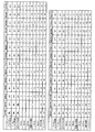
図12は、この発明の実施の形態にかかるプレキュア更生タイヤの性能試験の結果を示す表である。   FIG. 12 is a table showing the results of the performance test of the precure retreaded tire according to the embodiment of the present invention.

この性能試験では、相互に異なる複数のプレキュア更生タイヤについて、(1)耐久性能および(2)ユニフォミティに関する評価が行われた(図12参照)。この性能試験では、タイヤサイズ11R22.5のプレキュア更生タイヤがJATMA規定の適用リムに組み付けられ、このプレキュア更生タイヤにJATMA規定の最高空気圧および最大負荷が付与される。   In this performance test, (1) durability performance and (2) uniformity were evaluated for a plurality of different pre-cured retread tires (see FIG. 12). In this performance test, a pre-cured retread tire having a tire size of 11R22.5 is assembled to an applicable rim specified by JATMA, and the highest pressure and maximum load specified by JATMA are applied to the pre-cured retread tire.

(1)耐久性能に関する評価は、室内ドラム試験機を用いた低圧耐久試験により行われる。そして、走行速度を初速5[km/h]から12時間毎に1[km/h]ずつ増加させて、タイヤが故障するまでの走行時間が測定される。そして、この測定結果に基づいて従来例を基準(100)とした指数評価が行われる。この評価は、数値が大きいほど好ましい。   (1) The durability performance is evaluated by a low-pressure durability test using an indoor drum tester. Then, the travel speed is increased by 1 [km / h] every 12 hours from the initial speed of 5 [km / h], and the travel time until the tire breaks down is measured. Then, based on this measurement result, index evaluation using the conventional example as a reference (100) is performed. This evaluation is preferable as the numerical value increases.

(2)ユニフォミティに関する評価は、予め、タイヤユニフォミティ(ラテラルフォースバリエーション)がJASO C607「自動車用タイヤのユニフォミティ試験方法」に準拠して測定される。次に、室内ドラム試験機が用いられて、150[km/h]での30分間の予備走行が行われる。その後に、荷重を負荷した状態で1時間のドラム停止が行われる。その後に、再び、タイヤユニフォミティが測定されて従来例を基準(100)とした指数評価が行われる。この評価は、数値が大きいほど好ましい。   (2) For evaluation of uniformity, tire uniformity (lateral force variation) is measured in advance according to JASO C607 “Testing method for uniformity of automobile tires”. Next, the indoor drum tester is used, and a preliminary run for 30 minutes at 150 [km / h] is performed. After that, the drum is stopped for 1 hour with the load applied. Thereafter, the tire uniformity is measured again, and the index evaluation based on the conventional example as the standard (100) is performed. This evaluation is preferable as the numerical value increases.

実施例1〜10のプレキュア更生タイヤ1は、図1〜3に記載した構成を有する。また、プレキュアトレッド2の凹部23が、タイヤ周方向に連続する断面円弧状の環状溝であり、台タイヤ3の凸部31が周方向に連続する環状のリブである。また、プレキュアトレッド2の貫通孔24が、円形のピン孔であり、トレッド踏面側にて2.0[mm]の径Riを有する。また、複数の貫通孔24が、タイヤ周方向に等間隔で配置されている。また、クッションゴム4が一様なゲージGaを有する。また、プレキュアトレッド2の凹部23の開口幅Wおよび深さDと、台タイヤ3の凸部31の開口幅W’および深さD’と、クッションゴム4のゲージGaとが、W−W’−Ga=0.8[mm]かつD−D’−Ga0.8[mm]の関係に設定されている。   The precure retread tire 1 of Examples 1-10 has the structure described in FIGS. Further, the recess 23 of the precure tread 2 is an annular groove having a circular arc shape that is continuous in the tire circumferential direction, and the convex portion 31 of the base tire 3 is an annular rib that is continuous in the circumferential direction. The through hole 24 of the precure tread 2 is a circular pin hole and has a diameter Ri of 2.0 [mm] on the tread surface side. A plurality of through holes 24 are arranged at equal intervals in the tire circumferential direction. Further, the cushion rubber 4 has a uniform gauge Ga. Moreover, the opening width W and depth D of the recessed part 23 of the precure tread 2, the opening width W 'and depth D' of the convex part 31 of the base tire 3, and the gauge Ga of the cushion rubber 4 are W-W. The relationship is set to '-Ga = 0.8 [mm] and DD'-Ga0.8 [mm].

従来例1のプレキュア更生タイヤは、図1〜3の構成において、プレキュアトレッド2が凹部23および貫通孔24を有しておらず、また、台タイヤ3が凸部31を有していない。従来例2のプレキュア更生タイヤは、図1〜3の構成において、プレキュアトレッド2が凹部23および貫通孔24を有するが、また、台タイヤ3が凸部31を有していない。また、クッションゴム4が、凹部23および貫通孔24に充填されていない。   In the precure retread tire of Conventional Example 1, in the configuration of FIGS. 1 to 3, the precure tread 2 does not have the concave portion 23 and the through hole 24, and the base tire 3 does not have the convex portion 31. In the configuration of FIGS. 1 to 3, the precure retread tire of Conventional Example 2 has the concave portion 23 and the through hole 24, but the base tire 3 does not have the convex portion 31. Further, the cushion rubber 4 is not filled in the recess 23 and the through hole 24.

試験結果に示すように、実施例1〜10のプレキュア更生タイヤ1では、タイヤの耐久性能およびユニフォミティが向上することが分かる。   As shown in the test results, in the precure retreaded tire 1 of Examples 1 to 10, it can be seen that the durability performance and uniformity of the tire are improved.

1 プレキュア更生タイヤ、2 プレキュアトレッド、21 周方向主溝、22 陸部、23 凹部、24 貫通孔、3 台タイヤ、31 凸部、4 クッションゴム、11 ビードコア、12 ビードフィラー、13 カーカス層、14 ベルト層、15 トレッドゴム、16 サイドウォールゴム、17 リムクッションゴム、141〜144 ベルトプライ   DESCRIPTION OF SYMBOLS 1 Precure retread tire, 2 Precure tread, 21 Circumferential main groove, 22 Land part, 23 Recessed part, 24 Through hole, 3 tires, 31 Convex part, 4 Cushion rubber, 11 Bead core, 12 Bead filler, 13 Carcass layer, 14 belt layers, 15 tread rubber, 16 sidewall rubber, 17 rim cushion rubber, 141-144 belt ply

Claims (14)

プレキュアトレッドと、台タイヤと、前記プレキュアトレッドおよび前記台タイヤを接着するクッションゴムとを備え、且つ、タイヤ周方向に延在する複数の周方向主溝と、前記周方向主溝に区画されて成る複数の陸部とをトレッド面に備えるプレキュア更生タイヤであって、
前記プレキュアトレッドが、前記台タイヤとの接着面に形成される凹部と、前記凹部から前記陸部の踏面に貫通する貫通孔とを有し、
前記台タイヤが、前記クッションゴムを介して前記凹部に嵌合する凸部を有し、
前記プレキュアトレッドが、複数の前記凹部を有し、且つ、
前記凹部のうちタイヤ赤道面側にある前記凹部の深さが、ショルダー部側にある前記凹部の深さよりも大きいことを特徴とするプレキュア更生タイヤ。
A pre-cured tread, a base tire, and a cushion rubber that bonds the pre-cured tread and the base tire, and a plurality of circumferential main grooves extending in the tire circumferential direction, and partitioned into the circumferential main grooves It is a precure rehabilitation tire comprising a plurality of land portions formed on the tread surface,
The precured tread, possess a recess formed in the bonding surface between the base tire, and a through hole penetrating the tread surface of the land portion from the recess,
Said platform tire, have a convex portion to be fitted into the recess through the cushion rubber,
The precure tread has a plurality of the recesses, and
The precure retreaded tire characterized by the depth of the said recessed part in the tire equatorial plane side among the said recessed parts being larger than the depth of the said recessed part in the shoulder part side .
前記凹部が、タイヤ周方向に連続する環状溝であり、前記凸部が、タイヤ周方向に連続するリブである請求項1に記載のプレキュア更生タイヤ。   The precure retreaded tire according to claim 1, wherein the concave portion is an annular groove continuous in the tire circumferential direction, and the convex portion is a rib continuous in the tire circumferential direction. 前記貫通孔が、前記凹部の最深部に開口する請求項1または2に記載のプレキュア更生タイヤ。   The pre-cured retread tire according to claim 1 or 2, wherein the through hole opens at a deepest portion of the recess. 前記凹部が、前記凹部の深さ方向に向かうに連れて断面積を狭める請求項1〜3のいずれか一つに記載のプレキュア更生タイヤ。   The pre-cured retread tire according to any one of claims 1 to 3, wherein the concave portion narrows a cross-sectional area as it goes in a depth direction of the concave portion. 前記貫通孔が、前記凹部から前記陸部の踏面に向かうに連れて断面積を狭める請求項1〜4のいずれか一つに記載のプレキュア更生タイヤ。   The precure retreaded tire according to any one of claims 1 to 4, wherein the through-hole narrows a cross-sectional area as it goes from the concave portion toward the tread surface of the land portion. 前記凹部の開口幅Wおよび深さDが、3[mm]≦W≦25[mm]および1[mm]≦D≦5[mm]の範囲内にある請求項1〜5のいずれか一つに記載のプレキュア更生タイヤ。   The opening width W and depth D of the recess are in the range of 3 [mm] ≦ W ≦ 25 [mm] and 1 [mm] ≦ D ≦ 5 [mm]. Precure retreaded tire described in 1. 前記プレキュアトレッドが、複数の前記凹部を有し、且つ、タイヤ幅方向に隣り合う一対の前記凹部のうちタイヤ赤道面側にある前記凹部の幅W_ceと、ショルダー部側にある前記凹部の幅W_shとが、W_sh≦W_ceの関係を有する請求項1〜のいずれか一つに記載のプレキュア更生タイヤ。 The precure tread has a plurality of the recesses, and of the pair of recesses adjacent in the tire width direction, the width W_ce of the recess on the tire equatorial plane side and the width of the recess on the shoulder side. The precured retreaded tire according to any one of claims 1 to 6 , wherein W_sh has a relationship of W_sh ≦ W_ce. 前記凹部に対する前記貫通孔の開口幅Riが、1[mm]≦Ri≦8[mm]の範囲内にある請求項1〜のいずれか一つに記載のプレキュア更生タイヤ。 The precured retreaded tire according to any one of claims 1 to 7 , wherein an opening width Ri of the through hole with respect to the recess is in a range of 1 [mm] ≤ Ri ≤ 8 [mm]. 前記プレキュアトレッドが、複数の前記貫通孔を有し、且つ、少なくとも1つの前記貫通孔が、前記プレキュアトレッドをタイヤ周方向に8等分した各領域にそれぞれ配置される請求項1〜のいずれか一つに記載のプレキュア更生タイヤ。 The precured tread has a plurality of the through-hole, and, at least one of said through holes, said precured tread claims are arranged in each area which is divided into eight equal parts in the circumferential direction of the tire section 1-8 Precure retreaded tire as described in any one of these. タイヤ子午線方向の断面視における前記凹部の断面積Sdと、前記貫通孔の断面積Spとが、0.1≦Sd/Sp≦1.0の関係を有する請求項1〜のいずれか一つに記載のプレキュア更生タイヤ。 Claim 1-9 having a cross-sectional area Sd of the recess in the tire meridian direction of cross section, the cross-sectional area Sp of the through holes, the relationship 0.1 ≦ Sd / Sp ≦ 1.0 Precure retreaded tire described in 1. 前記凹部と、前記周方向主溝とが、タイヤ幅方向に相互に位置をずらして配置される請求項1〜10のいずれか一つに記載のプレキュア更生タイヤ。 The precure retreaded tire according to any one of claims 1 to 10 , wherein the concave portion and the circumferential main groove are disposed so as to be shifted from each other in the tire width direction. 前記クッションゴムのゲージGaが、0.8[mm]≦Ga≦2.0[mm]の範囲内にある請求項1〜11のいずれか一つに記載のプレキュア更生タイヤ。 The precure retreaded tire according to any one of claims 1 to 11 , wherein a gauge Ga of the cushion rubber is in a range of 0.8 [mm]? Ga? 2.0 [mm]. プレキュアトレッドと、台タイヤと、前記プレキュアトレッドおよび前記台タイヤを接着するクッションゴムとを備え、且つ、タイヤ周方向に延在する複数の周方向主溝と、前記周方向主溝に区画されて成る複数の陸部とをトレッド面に備えるプレキュア更生タイヤであって、  A pre-cured tread, a base tire, and a cushion rubber that bonds the pre-cured tread and the base tire, and a plurality of circumferential main grooves extending in the tire circumferential direction, and partitioned into the circumferential main grooves It is a precure rehabilitation tire comprising a plurality of land portions formed on the tread surface,
前記プレキュアトレッドが、前記台タイヤとの接着面に形成される凹部と、前記凹部から前記陸部の踏面に貫通する貫通孔とを有し、  The precure tread has a recess formed in an adhesive surface with the base tire, and a through-hole penetrating from the recess to the tread surface of the land portion,
前記台タイヤが、前記クッションゴムを介して前記凹部に嵌合する凸部を有し、  The base tire has a convex portion that fits into the concave portion via the cushion rubber,
前記プレキュアトレッドが、複数の前記凹部を有し、且つ、  The precure tread has a plurality of the recesses, and
タイヤ幅方向に隣り合う一対の前記凹部のうちタイヤ赤道面側にある前記凹部の幅が、ショルダー部側にある前記凹部の幅よりも大きいことを特徴とするプレキュア更生タイヤ。  The pre-cured retread tire characterized in that the width of the concave portion on the tire equatorial plane side is larger than the width of the concave portion on the shoulder portion side among the pair of concave portions adjacent in the tire width direction.
プレキュアトレッドと、台タイヤと、前記プレキュアトレッドおよび前記台タイヤを接着するクッションゴムとを備え、且つ、タイヤ周方向に延在する複数の周方向主溝と、前記周方向主溝に区画されて成る複数の陸部とをトレッド面に備えるプレキュア更生タイヤであって、  A pre-cured tread, a base tire, and a cushion rubber that bonds the pre-cured tread and the base tire, and a plurality of circumferential main grooves extending in the tire circumferential direction, and partitioned into the circumferential main grooves It is a precure rehabilitation tire comprising a plurality of land portions formed on the tread surface,
前記プレキュアトレッドが、前記台タイヤとの接着面に形成される凹部と、前記凹部から前記陸部の踏面に貫通する貫通孔とを有し、  The precure tread has a recess formed in an adhesive surface with the base tire, and a through-hole penetrating from the recess to the tread surface of the land portion,
前記台タイヤが、前記クッションゴムを介して前記凹部に嵌合する凸部を有し、且つ、  The pedestal tire has a convex part that fits into the concave part via the cushion rubber; and
前記貫通孔が、前記凹部から前記陸部の踏面に向かうに連れて断面積を狭めることを特徴とするプレキュア更生タイヤ。  The pre-cured retread tire, wherein the through-hole narrows the cross-sectional area from the concave portion toward the tread surface of the land portion.
JP2012121244A 2012-05-28 2012-05-28 Precure retread tire Expired - Fee Related JP5958085B2 (en)

Priority Applications (1)

Application Number Priority Date Filing Date Title
JP2012121244A JP5958085B2 (en) 2012-05-28 2012-05-28 Precure retread tire

Applications Claiming Priority (1)

Application Number Priority Date Filing Date Title
JP2012121244A JP5958085B2 (en) 2012-05-28 2012-05-28 Precure retread tire

Publications (2)

Publication Number Publication Date
JP2013244911A JP2013244911A (en) 2013-12-09
JP5958085B2 true JP5958085B2 (en) 2016-07-27

Family

ID=49845011

Family Applications (1)

Application Number Title Priority Date Filing Date
JP2012121244A Expired - Fee Related JP5958085B2 (en) 2012-05-28 2012-05-28 Precure retread tire

Country Status (1)

Country Link
JP (1) JP5958085B2 (en)

Families Citing this family (2)

* Cited by examiner, † Cited by third party
Publication number Priority date Publication date Assignee Title
JP6558201B2 (en) * 2015-10-19 2019-08-14 住友ゴム工業株式会社 Airless tire
JP6762857B2 (en) * 2016-11-21 2020-09-30 株式会社ブリヂストン Non-pneumatic tires

Family Cites Families (4)

* Cited by examiner, † Cited by third party
Publication number Priority date Publication date Assignee Title
JPH05154941A (en) * 1991-12-03 1993-06-22 Bridgestone Corp Manufacture of recap tire and recap tire itself
JP2007331152A (en) * 2006-06-13 2007-12-27 Bridgestone Corp Tire regeneration method using precured tread
JP5609258B2 (en) * 2010-05-21 2014-10-22 横浜ゴム株式会社 Rehabilitated tire and manufacturing method thereof
JP5560900B2 (en) * 2010-05-21 2014-07-30 横浜ゴム株式会社 Rehabilitated tire and manufacturing method thereof

Also Published As

Publication number Publication date
JP2013244911A (en) 2013-12-09

Similar Documents

Publication Publication Date Title
US10857835B2 (en) Pneumatic tire and method for manufacturing the same
JP5977566B2 (en) Pneumatic radial tire and method for manufacturing pneumatic radial tire
JP6085940B2 (en) Rehabilitation tire
JP6032242B2 (en) Rehabilitation tire
US11052708B2 (en) Pneumatic tire
WO2020158265A1 (en) Pneumatic tire
JP6052227B2 (en) Rehabilitation tire
JP6065432B2 (en) Precure retread tire
JP6269306B2 (en) Rehabilitation tire
JP5958085B2 (en) Precure retread tire
JP6701654B2 (en) Retreaded tires
JP2016020111A (en) Retreaded tire
JP6221788B2 (en) Rehabilitation tire
JP5966638B2 (en) Precure retread tire
JP6221789B2 (en) Rehabilitation tire
JP2014004929A (en) Pneumatic tire, and method for producing the same
JP6056360B2 (en) Rehabilitation tire
JP6369184B2 (en) Rehabilitation tire
EP3006230B1 (en) Tire and tire manufacturing method
JP2015145141A (en) retreaded tire
JP5978786B2 (en) Precure retread tire
JP6007486B2 (en) Precure tread and precure retreaded tire
JP5966334B2 (en) Precure tread and precure retreaded tire
JP6269156B2 (en) Rehabilitation tire
JP6085939B2 (en) Rehabilitation tire

Legal Events

Date Code Title Description
A621 Written request for application examination

Free format text: JAPANESE INTERMEDIATE CODE: A621

Effective date: 20150511

A131 Notification of reasons for refusal

Free format text: JAPANESE INTERMEDIATE CODE: A131

Effective date: 20160216

A977 Report on retrieval

Free format text: JAPANESE INTERMEDIATE CODE: A971007

Effective date: 20160217

A521 Written amendment

Free format text: JAPANESE INTERMEDIATE CODE: A523

Effective date: 20160418

TRDD Decision of grant or rejection written
A01 Written decision to grant a patent or to grant a registration (utility model)

Free format text: JAPANESE INTERMEDIATE CODE: A01

Effective date: 20160524

A61 First payment of annual fees (during grant procedure)

Free format text: JAPANESE INTERMEDIATE CODE: A61

Effective date: 20160606

R150 Certificate of patent or registration of utility model

Ref document number: 5958085

Country of ref document: JP

Free format text: JAPANESE INTERMEDIATE CODE: R150

LAPS Cancellation because of no payment of annual fees