JP5954259B2 - Method for producing exhaust gas purifying catalyst - Google Patents
Method for producing exhaust gas purifying catalyst Download PDFInfo
- Publication number
- JP5954259B2 JP5954259B2 JP2013110769A JP2013110769A JP5954259B2 JP 5954259 B2 JP5954259 B2 JP 5954259B2 JP 2013110769 A JP2013110769 A JP 2013110769A JP 2013110769 A JP2013110769 A JP 2013110769A JP 5954259 B2 JP5954259 B2 JP 5954259B2
- Authority
- JP
- Japan
- Prior art keywords
- catalyst
- layer
- nox
- exhaust gas
- gas
- Prior art date
- Legal status (The legal status is an assumption and is not a legal conclusion. Google has not performed a legal analysis and makes no representation as to the accuracy of the status listed.)
- Expired - Fee Related
Links
- 239000003054 catalyst Substances 0.000 title claims description 104
- 238000004519 manufacturing process Methods 0.000 title claims description 19
- 239000010410 layer Substances 0.000 claims description 64
- 229910021536 Zeolite Inorganic materials 0.000 claims description 28
- 238000000746 purification Methods 0.000 claims description 28
- 239000010457 zeolite Substances 0.000 claims description 28
- HNPSIPDUKPIQMN-UHFFFAOYSA-N dioxosilane;oxo(oxoalumanyloxy)alumane Chemical compound O=[Si]=O.O=[Al]O[Al]=O HNPSIPDUKPIQMN-UHFFFAOYSA-N 0.000 claims description 26
- 230000003647 oxidation Effects 0.000 claims description 16
- 238000007254 oxidation reaction Methods 0.000 claims description 16
- 239000011232 storage material Substances 0.000 claims description 16
- 229910052751 metal Inorganic materials 0.000 claims description 13
- 239000002184 metal Substances 0.000 claims description 13
- 239000000203 mixture Substances 0.000 claims description 12
- PNEYBMLMFCGWSK-UHFFFAOYSA-N aluminium oxide Inorganic materials [O-2].[O-2].[O-2].[Al+3].[Al+3] PNEYBMLMFCGWSK-UHFFFAOYSA-N 0.000 claims description 10
- 230000003197 catalytic effect Effects 0.000 claims description 8
- 239000002344 surface layer Substances 0.000 claims description 7
- 239000011358 absorbing material Substances 0.000 claims description 5
- 239000011248 coating agent Substances 0.000 claims description 5
- 238000000576 coating method Methods 0.000 claims description 5
- 238000000034 method Methods 0.000 claims description 5
- 229910052788 barium Inorganic materials 0.000 claims description 2
- 229910052712 strontium Inorganic materials 0.000 claims description 2
- 230000001180 sulfating effect Effects 0.000 claims 1
- MWUXSHHQAYIFBG-UHFFFAOYSA-N Nitric oxide Chemical compound O=[N] MWUXSHHQAYIFBG-UHFFFAOYSA-N 0.000 description 244
- 239000007789 gas Substances 0.000 description 93
- 239000000463 material Substances 0.000 description 38
- 239000000843 powder Substances 0.000 description 20
- 239000002002 slurry Substances 0.000 description 17
- 210000004027 cell Anatomy 0.000 description 14
- 230000000052 comparative effect Effects 0.000 description 10
- 239000000446 fuel Substances 0.000 description 10
- 210000002421 cell wall Anatomy 0.000 description 8
- 238000001179 sorption measurement Methods 0.000 description 8
- 230000007423 decrease Effects 0.000 description 6
- 238000005259 measurement Methods 0.000 description 6
- 238000012360 testing method Methods 0.000 description 6
- 239000003463 adsorbent Substances 0.000 description 5
- 239000002612 dispersion medium Substances 0.000 description 5
- 229910052739 hydrogen Inorganic materials 0.000 description 5
- 238000002360 preparation method Methods 0.000 description 5
- XLYOFNOQVPJJNP-UHFFFAOYSA-N water Substances O XLYOFNOQVPJJNP-UHFFFAOYSA-N 0.000 description 5
- 229910052784 alkaline earth metal Inorganic materials 0.000 description 4
- 238000001354 calcination Methods 0.000 description 4
- 229910002091 carbon monoxide Inorganic materials 0.000 description 4
- 238000006243 chemical reaction Methods 0.000 description 4
- 238000010828 elution Methods 0.000 description 4
- 229910052697 platinum Inorganic materials 0.000 description 4
- 238000003860 storage Methods 0.000 description 4
- GRYLNZFGIOXLOG-UHFFFAOYSA-N Nitric acid Chemical compound O[N+]([O-])=O GRYLNZFGIOXLOG-UHFFFAOYSA-N 0.000 description 3
- 150000001342 alkaline earth metals Chemical class 0.000 description 3
- 239000007864 aqueous solution Substances 0.000 description 3
- 230000000694 effects Effects 0.000 description 3
- -1 first Substances 0.000 description 3
- 238000010438 heat treatment Methods 0.000 description 3
- 229910017604 nitric acid Inorganic materials 0.000 description 3
- 229910052760 oxygen Inorganic materials 0.000 description 3
- 239000012466 permeate Substances 0.000 description 3
- 230000009467 reduction Effects 0.000 description 3
- 229910002651 NO3 Inorganic materials 0.000 description 2
- NHNBFGGVMKEFGY-UHFFFAOYSA-N Nitrate Chemical compound [O-][N+]([O-])=O NHNBFGGVMKEFGY-UHFFFAOYSA-N 0.000 description 2
- 230000032683 aging Effects 0.000 description 2
- 229910052783 alkali metal Inorganic materials 0.000 description 2
- 150000001340 alkali metals Chemical class 0.000 description 2
- 239000011230 binding agent Substances 0.000 description 2
- 239000003638 chemical reducing agent Substances 0.000 description 2
- 238000011278 co-treatment Methods 0.000 description 2
- 229910052878 cordierite Inorganic materials 0.000 description 2
- 230000003247 decreasing effect Effects 0.000 description 2
- JSKIRARMQDRGJZ-UHFFFAOYSA-N dimagnesium dioxido-bis[(1-oxido-3-oxo-2,4,6,8,9-pentaoxa-1,3-disila-5,7-dialuminabicyclo[3.3.1]nonan-7-yl)oxy]silane Chemical compound [Mg++].[Mg++].[O-][Si]([O-])(O[Al]1O[Al]2O[Si](=O)O[Si]([O-])(O1)O2)O[Al]1O[Al]2O[Si](=O)O[Si]([O-])(O1)O2 JSKIRARMQDRGJZ-UHFFFAOYSA-N 0.000 description 2
- 230000003993 interaction Effects 0.000 description 2
- 239000002609 medium Substances 0.000 description 2
- 150000002739 metals Chemical class 0.000 description 2
- 229910052763 palladium Inorganic materials 0.000 description 2
- 239000013618 particulate matter Substances 0.000 description 2
- 229910052703 rhodium Inorganic materials 0.000 description 2
- 239000000243 solution Substances 0.000 description 2
- 238000003756 stirring Methods 0.000 description 2
- 230000019635 sulfation Effects 0.000 description 2
- 238000005670 sulfation reaction Methods 0.000 description 2
- BVKZGUZCCUSVTD-UHFFFAOYSA-L Carbonate Chemical compound [O-]C([O-])=O BVKZGUZCCUSVTD-UHFFFAOYSA-L 0.000 description 1
- VGGSQFUCUMXWEO-UHFFFAOYSA-N Ethene Chemical compound C=C VGGSQFUCUMXWEO-UHFFFAOYSA-N 0.000 description 1
- 239000005977 Ethylene Substances 0.000 description 1
- UFHFLCQGNIYNRP-UHFFFAOYSA-N Hydrogen Chemical compound [H][H] UFHFLCQGNIYNRP-UHFFFAOYSA-N 0.000 description 1
- NINIDFKCEFEMDL-UHFFFAOYSA-N Sulfur Chemical compound [S] NINIDFKCEFEMDL-UHFFFAOYSA-N 0.000 description 1
- 239000002253 acid Substances 0.000 description 1
- 230000002378 acidificating effect Effects 0.000 description 1
- 230000002411 adverse Effects 0.000 description 1
- 229910000323 aluminium silicate Inorganic materials 0.000 description 1
- QVGXLLKOCUKJST-UHFFFAOYSA-N atomic oxygen Chemical compound [O] QVGXLLKOCUKJST-UHFFFAOYSA-N 0.000 description 1
- 238000006555 catalytic reaction Methods 0.000 description 1
- 230000008859 change Effects 0.000 description 1
- 238000002485 combustion reaction Methods 0.000 description 1
- 239000002131 composite material Substances 0.000 description 1
- 238000003795 desorption Methods 0.000 description 1
- 239000006185 dispersion Substances 0.000 description 1
- 238000011156 evaluation Methods 0.000 description 1
- 238000001704 evaporation Methods 0.000 description 1
- 230000008020 evaporation Effects 0.000 description 1
- 238000010304 firing Methods 0.000 description 1
- 239000011521 glass Substances 0.000 description 1
- 238000000227 grinding Methods 0.000 description 1
- 229930195733 hydrocarbon Natural products 0.000 description 1
- 150000002430 hydrocarbons Chemical class 0.000 description 1
- 239000001257 hydrogen Substances 0.000 description 1
- 238000002156 mixing Methods 0.000 description 1
- IJGRMHOSHXDMSA-UHFFFAOYSA-N nitrogen Substances N#N IJGRMHOSHXDMSA-UHFFFAOYSA-N 0.000 description 1
- 229910052757 nitrogen Inorganic materials 0.000 description 1
- QJGQUHMNIGDVPM-UHFFFAOYSA-N nitrogen group Chemical group [N] QJGQUHMNIGDVPM-UHFFFAOYSA-N 0.000 description 1
- TVMXDCGIABBOFY-UHFFFAOYSA-N octane Chemical compound CCCCCCCC TVMXDCGIABBOFY-UHFFFAOYSA-N 0.000 description 1
- 230000001590 oxidative effect Effects 0.000 description 1
- 239000001301 oxygen Substances 0.000 description 1
- 230000035515 penetration Effects 0.000 description 1
- 231100000572 poisoning Toxicity 0.000 description 1
- 230000000607 poisoning effect Effects 0.000 description 1
- 238000012545 processing Methods 0.000 description 1
- 239000000047 product Substances 0.000 description 1
- 230000001737 promoting effect Effects 0.000 description 1
- QQONPFPTGQHPMA-UHFFFAOYSA-N propylene Natural products CC=C QQONPFPTGQHPMA-UHFFFAOYSA-N 0.000 description 1
- 125000004805 propylene group Chemical group [H]C([H])([H])C([H])([*:1])C([H])([H])[*:2] 0.000 description 1
- 238000010298 pulverizing process Methods 0.000 description 1
- 238000010926 purge Methods 0.000 description 1
- 239000007787 solid Substances 0.000 description 1
- 229910052717 sulfur Inorganic materials 0.000 description 1
- 239000011593 sulfur Substances 0.000 description 1
- 230000001629 suppression Effects 0.000 description 1
- 230000008719 thickening Effects 0.000 description 1
Images


Landscapes
- Exhaust Gas Treatment By Means Of Catalyst (AREA)
- Catalysts (AREA)
- Exhaust Gas After Treatment (AREA)
Description
本発明は、排気ガス浄化用触媒の製造方法に関し、特に、NOx吸蔵材を含む排気ガス浄化用触媒の製造方法に関する。 The present invention relates to a method of manufacturing a catalyst for purifying exhaust gases medium, more particularly to a method of manufacturing a catalyze for purifying exhaust gases containing NOx-absorbing material.
ディーゼルエンジンの排気ガス処理装置は、一般にディーゼル酸化触媒(DOC)とその下流に配設されたディーゼルパティキュレートフィルタ(DPF)によって構成されている。DOCによって、排気ガス中のHC(炭化水素)及びCOが酸化浄化され、NOx(窒素酸化物)のうちのNOがNO2に酸化される。DOCでの触媒反応熱によりDPFの昇温が図れ、NO2の有する強い酸化力によりDPFに堆積したパティキュレートマター(PM)の燃焼が促進される。エンジン始動直後はDOCの活性が低いことから、HCが未浄化のまま排出されないように、DOCにゼオライトをHCトラップ材として設けることが行われている。 An exhaust gas treatment device for a diesel engine is generally constituted by a diesel oxidation catalyst (DOC) and a diesel particulate filter (DPF) disposed downstream thereof. By DOC, HC (hydrocarbons) and CO in the exhaust gas is oxidized and purified, NO of NOx (nitrogen oxide) is oxidized to NO 2. The temperature of the DPF can be increased by the catalytic reaction heat in the DOC, and the combustion of particulate matter (PM) deposited on the DPF is promoted by the strong oxidizing power of NO 2 . Since the activity of DOC is low immediately after the engine is started, zeolite is provided in the DOC as an HC trap material so that HC is not discharged without being purified.
一方、NOxの浄化のために、リーンバーンガソリンエンジンやディーゼルエンジンではリーンNOxトラップ触媒(LNT触媒)も利用されている。このLNT触媒は、NOx吸蔵材によって排気ガスの空燃比がリーンであるときにNOxを吸蔵する。そして、エンジンの空燃比をリッチに変調するリッチパージにより、NOx吸蔵材からのNOxの放出、及び未燃ガスによるNOxの還元が行なわれる。NOx吸蔵材としては、アルカリ金属やアルカリ土類金属を利用することが可能である。但し、アルカリ金属は触媒担体を形成するコージェライトの粒界にガラス相を形成して担体強度を低下させることから、実際にはそのような問題がないアルカリ土類金属が一般に採用されている。 On the other hand, lean NOx trap catalysts (LNT catalysts) are also used for lean burn gasoline engines and diesel engines for NOx purification. This LNT catalyst occludes NOx when the air-fuel ratio of the exhaust gas is lean by the NOx occlusion material. The rich purge that richly modulates the air-fuel ratio of the engine releases NOx from the NOx occlusion material and reduces NOx with unburned gas. As the NOx occlusion material, it is possible to use an alkali metal or an alkaline earth metal. However, since an alkali metal reduces the support strength by forming a glass phase at the cordierite grain boundary forming the catalyst support, an alkaline earth metal that does not have such a problem is generally employed.
ところで、特許文献1に記載されているように、ガソリンエンジンの排気ガス浄化用触媒においては、一体構造型担体にゼオライト含有するHC吸着材層とNOx吸蔵材を含有する触媒金属層とを積層状態に設けるという提案がある。この提案では、HC吸着材層にもNOx吸蔵材が含まれ、重量比でHC吸着材層のNOx吸着材量が触媒金属層のNOx吸着材量の40/60から1/99とされている。
Incidentally, as described in
ディーゼルエンジンの排気ガスの浄化においても、一体構造型担体に、NOx吸蔵材を含有するLNT触媒層とゼオライトを含有するDOC層とを層状に設けることが考えられる。しかし、特許文献1でも示唆されているが、排気ガス浄化用触媒の製造過程でNOx吸蔵材がスラリー中に溶出してLNT触媒層からDOC層に浸透すると、そのDOC層の触媒性能低下を招く。例えば、NOx吸蔵材の浸透によって、DOC層に含まれるゼオライトのHC吸着性能が低下し、或いは酸化触媒性能が低下する。
In purifying exhaust gas from a diesel engine, it is conceivable to provide an LNT catalyst layer containing a NOx occlusion material and a DOC layer containing zeolite in a layered structure on an integral structure type carrier. However, as suggested in
本発明は、前記の問題に鑑みてなされたものであり、その目的は、NOx吸蔵材を含有する積層型の排気ガス浄化触媒において、そのNOx吸蔵材がゼオライトなど他の触媒成分に悪影響を及ぼさないようにすることにある。 The present invention has been made in view of the above problems, and an object of the present invention is to provide a stack type exhaust gas purification catalyst containing a NOx storage material, in which the NOx storage material adversely affects other catalyst components such as zeolite. There is to be no.
前記の目的を達成するために、本発明は、排気ガス浄化用触媒において、NOx吸蔵材とゼオライトとを互いに別の触媒層に設けるようにした。 In order to achieve the above object, according to the present invention, in the exhaust gas purifying catalyst, the NOx storage material and the zeolite are provided in separate catalyst layers.
本発明に係る排気ガス浄化用触媒の製造方法は、Ba又はSrよりなるNOx吸蔵材とゼオライトとを含む排気ガス浄化用触媒の製造方法であって、担体上に、ゼオライト、アルミナ、Ce含有酸化物及び触媒金属を含み且つ前記NOx吸蔵材を添加していない酸化触媒層を形成する工程と、アルミナとCe含有酸化物との混合物に、前記NOx吸蔵材と触媒金属とを担持する工程と、担持された混合物にSO 2 ガス処理をすることにより、前記NOx吸蔵材の表層部を硫酸塩化する工程と、前記SO2ガス処理された混合物をスラリー化し、酸化触媒層にコーティングすることによりLNT(リーンNOxトラップ)層を形成する工程と、前記NOx吸蔵材をCOガスにより炭酸塩化する工程とを備えていることを特徴とする。 A method for producing an exhaust gas purifying catalyst according to the present invention is a method for producing an exhaust gas purifying catalyst containing a NOx storage material made of Ba or Sr and zeolite, on a carrier, containing zeolite, alumina, and Ce containing oxidation forming an oxidation catalyst layer without added and include mono and catalytic metal the NOx-absorbing material, a mixture of alumina and Ce-containing oxide, and a step of carrying the catalyst metal the NOx-absorbing material, by the SO 2 gas processing supported mixture the steps of the surface layer portion to sulfated of the NOx occlusion material, the SO 2 gas treated mixture was slurried, LNT by coating the oxidation catalyst layer ( forming a lean NOx trap) layer, characterized in that the NOx-absorbing material and a step of carbonating the CO gas.
本発明に係る排気ガス浄化用触媒の製造方法によると、NOx吸蔵材は予めその表層部が硫酸塩化されているので、スラリー中の酸成分に対して安定となり、NOx吸蔵材がコーティング用のスラリー分散媒に溶出することが抑制される。このため、その分散媒が酸化触媒層に浸透しても、NOx吸蔵材が酸化触媒層に混入することが抑制される。また、NOx吸蔵材は、前記スラリーが酸化触媒層上にコーティングされた後に炭酸塩化されるため、本来のNOx吸蔵性能を有する状態となる。また、NOx吸蔵材は、その表層部が硫酸塩化されているため、NOx吸蔵材の炭酸塩化を容易にでき、NOx吸蔵性能の確保に有利となる。 According to the method for producing an exhaust gas purifying catalyst according to the present invention, since the surface layer portion of the NOx occlusion material is sulfated in advance, the NOx occlusion material becomes stable against the acid component in the slurry, and the NOx occlusion material is a slurry for coating. Elution to the dispersion medium is suppressed . For this reason, even if the dispersion medium permeates the oxidation catalyst layer, the NOx storage material is suppressed from being mixed into the oxidation catalyst layer. Further, the NOx occlusion material is carbonated after the slurry is coated on the oxidation catalyst layer, and thus has a state of original NOx occlusion performance. Further, since the surface layer portion of the NOx occlusion material is sulfated, the NOx occlusion material can be easily carbonated, which is advantageous in ensuring NOx occlusion performance.
前記製造方法で得られる排気ガス浄化用触媒においては、触媒温度が低いときは排気ガス中のHCが酸化触媒層のゼオライトに吸着され、触媒温度が上昇すると、ゼオライトからHCが放出される。放出されたHCは、排気ガス中のCOと共に温度上昇によって活性が高くなっている触媒金属により酸化浄化される。また、排気ガスの空燃比がリーンであるときは、NOxがLNT層のNOx吸蔵材に吸蔵され、その空燃比が理論空燃比近傍又はリッチになったときにNOx吸蔵材からNOxが放出される。放出されたNOxは、触媒金属により還元浄化される。また、Ce含有酸化物によるNOxの吸着によって全体のNOx吸蔵、吸着量が増大するとともに、Ce含有酸化物を介する水性ガスシフト反応によってNOx還元剤としての水素が生成し、NOxの還元が促進される。さらに、空燃比をリッチ側にしたときに、Ce含有酸化物に吸蔵された酸素と還元剤(HC及びCO)との反応熱による触媒の活性促進が図れ、NOx浄化率が向上する。 In the exhaust gas purifying catalyst obtained by the production method, HC in the exhaust gas is adsorbed by the zeolite in the oxidation catalyst layer when the catalyst temperature is low, and HC is released from the zeolite when the catalyst temperature rises. The released HC is oxidized and purified by the catalytic metal whose activity is increased by the temperature rise together with the CO in the exhaust gas. Further, when the air-fuel ratio of the exhaust gas is lean, NOx is occluded by the NOx occlusion material in the LNT layer, and NOx is released from the NOx occlusion material when the air-fuel ratio becomes near the stoichiometric air-fuel ratio or becomes rich. . The released NOx is reduced and purified by the catalytic metal. In addition, NOx occlusion and adsorption amount are increased by adsorption of NOx by Ce-containing oxides, and hydrogen as a NOx reducing agent is generated by a water gas shift reaction via Ce-containing oxides, thereby promoting reduction of NOx. . Further, when the air-fuel ratio is made rich, the catalyst activity can be promoted by the reaction heat between oxygen stored in the Ce-containing oxide and the reducing agents (HC and CO), and the NOx purification rate is improved.
また、前記製造方法によると、NOx吸蔵材とゼオライトとが混合状態になることが抑制されるため、NOx吸蔵材とゼオライトとの相互作用によるNOx吸蔵性能及びHC吸着性能の少なくとも一方の低下を抑制することができる。 Further, according to the manufacturing method, since the mixed state of the NOx storage material and the zeolite is suppressed, the decrease in at least one of the NOx storage performance and the HC adsorption performance due to the interaction between the NOx storage material and the zeolite is suppressed. can do.
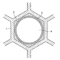
本発明に係る排気ガス浄化用触媒の製造方法において、担体として、セル断面形状が六角形である六角セルハニカム構造の担体を用いることが好ましい。 In the method for producing an exhaust gas purifying catalyst according to the present invention, it is preferable to use a hexagonal cell honeycomb structure carrier having a hexagonal cell cross-sectional shape as the carrier.
このようにすると、六角セルでは、セルの角部の角度が大きくなる(120度前後になる)から、三角セルや四角セルに比べて、触媒層がセルの角部(隅部)において局部的に厚くなる度合が小さくなる。つまり、触媒層厚さの均一化に有利になり、排気ガスを触媒層に効率良く接触させることができる。また、このことは、所期の触媒効果を得るに必要な触媒量を減らすことができることを意味する。これにより、コスト低減が図れるとともに、セルにおける排気ガス流路が広くなり、エンジンの背圧上昇(エンジン出力の低下)の防止に有利になる。 In this case, in the hexagonal cell, the angle of the cell corner becomes large (around 120 degrees), so that the catalyst layer is localized at the corner (corner) of the cell compared to the triangular cell or the square cell. The degree of thickening becomes smaller. In other words, be advantageous to uniformity of the catalyst layer thickness, the exhaust gas Ru can be efficiently contacted with the catalyst layer. This also means that the amount of catalyst required to obtain the desired catalytic effect can be reduced. As a result, the cost can be reduced and the exhaust gas flow path in the cell is widened, which is advantageous in preventing an increase in engine back pressure (decrease in engine output) .
本発明に係る排気ガス浄化用触媒の製造方法によると、NOx吸蔵材は予めその表層部が硫酸塩化されているので、NOx吸蔵材がコーティング用のスラリー分散媒に溶出することが抑制され、従って、その分散媒が酸化触媒層に浸透しても、NOx吸蔵材が酸化触媒層に混入することが抑制され、NOx吸蔵材とゼオライトとの相互作用によるNOx吸蔵性能及びHC吸着性能の低下防止に有利になる。 According to the method for producing an exhaust gas purifying catalyst according to the present invention, since the surface layer portion of the NOx occlusion material is sulfated in advance, it is suppressed that the NOx occlusion material is eluted into the slurry dispersion medium for coating. Even if the dispersion medium permeates the oxidation catalyst layer, the NOx occlusion material is prevented from entering the oxidation catalyst layer, and the NOx occlusion performance and HC adsorption performance are prevented from being lowered due to the interaction between the NOx occlusion material and zeolite. Become advantageous .
以下、本発明を実施するための形態を図面に基づいて説明する。以下の好ましい実施形態の説明は、本質的に例示に過ぎず、本発明、その適用方法或いはその用途を制限することを意図するものでない。 Hereinafter, embodiments for carrying out the present invention will be described with reference to the drawings. The following description of the preferred embodiments is merely exemplary in nature and is not intended to limit the invention, its method of application, or its application.
まず、本発明の一実施形態に係る排気ガス浄化用触媒の構成について図1及び図2を参照しながら説明する。図1は本実施形態に係る排気ガス浄化用触媒の一部を示す断面図であり、図2は該排気ガス浄化用触媒の触媒層構成を示す断面図である。 First, the configuration of an exhaust gas purifying catalyst according to an embodiment of the present invention will be described with reference to FIGS. 1 and 2. FIG. 1 is a cross-sectional view showing a part of an exhaust gas purification catalyst according to the present embodiment, and FIG. 2 is a cross-sectional view showing a catalyst layer structure of the exhaust gas purification catalyst.
図1及び図2に示すように、本実施形態に係る排気ガス浄化用触媒は、不図示のディーゼルエンジンから排出される排気ガス浄化用触媒であり、ハニカム担体のセル壁1の上に、酸化触媒層であるDOC層2及びリーンNOxトラップ触媒層であるLNT層3が順次形成されてなり、その内側の空間が排気ガス通路4となっている。ハニカム担体は、そのセル断面形状が六角形である六角セルハニカム構造となっている。図1では、図の簡略化のため、1つのセルにのみ上記触媒層を描いているが、全てのセルに上記触媒層が形成されている。
As shown in FIGS. 1 and 2, the exhaust gas purifying catalyst according to the present embodiment is an exhaust gas purifying catalyst discharged from a diesel engine (not shown), and is oxidized on the
DOC層2は、担体のセル壁1の上に形成されており、それはゼオライト、活性アルミナ及びCe含有酸化物の混合物にPt及びPd等の触媒金属が担持されてなる。ここで、DOC層2にはNOx吸蔵材が含まれていない。また、DOC層2の上に形成されたLNT層3は、活性アルミナ及びCe含有酸化物にNOx吸蔵材並びに触媒金属としてPt及びRh等が担持されてなる。
The
次に、本実施形態に係る排気ガス浄化用触媒の製造方法について図3を参照しながら説明する。図3は本実施形態に係る排気ガス浄化用触媒の製造方法を示すフローチャート図である。 Next, the manufacturing method of the exhaust gas purifying catalyst according to the present embodiment will be described with reference to FIG. FIG. 3 is a flowchart showing a method for manufacturing the exhaust gas purifying catalyst according to the present embodiment.
まず、担体のセル壁の上に形成するDOC層2の材料となるDOC粉末の調製について説明する。DOC粉末の調製としては、まず、ゼオライト、活性アルミナ及びCe含有酸化物を混合し、その混合物にPt及びPd等の触媒金属を蒸発乾固法により担持する。具体的に、ゼオライト、活性アルミナ及びCe含有酸化物の混合物に水を加え、撹拌してスラリー状にする。このスラリーを撹拌しながら、これに触媒金属の硝酸塩水溶液を滴下する。その後、加熱しながらさらに撹拌を続けて、水分を完全に蒸発させる。得られた乾固物を大気中で焼成し、粉砕することにより、DOC粉末が得られる。
First, preparation of the DOC powder used as the material of the
上記のように調製したDOC粉末を用いて、ハニカム担体のセル壁1の上にDOC層2を形成する。そのために、まず、得られたDOC粉末をバインダー及び水と混合し、さらにスラリー粘度調整用の硝酸水溶液を添加して撹拌することにより、スラリー状にする(スラリー化)。このスラリーをハニカム担体のセル壁1の上にコーティングし、乾燥し、その後に焼成する。これにより、担体のセル壁の上にDOC層2が形成される。
A
次に、DOC層2の上に形成するLNT層3の材料となるLNT粉末の調製について説明する。LNT粉末の調製のために、まず、活性アルミナとCe含有酸化物とを混合し、その混合物にPt及びRh等の触媒金属とアルカリ土類金属であるNOx吸蔵材を、上記と同様に蒸発乾固法により担持する。なお、このとき、NOx吸蔵材は、アルカリ土類金属の酢酸塩又は硝酸塩の水溶液を用いる。その後、上記と同様に、焼成及び粉砕を行うことにより、LNT粉末が得られる。得られたLNT粉末におけるNOx吸蔵材の少なくとも一部は、大気中での焼成により炭酸塩となっている。
Next, preparation of the LNT powder used as the material of the
次に、そのLNT粉末のNOx吸蔵材の表層部を硫酸塩化する。この硫酸塩化は、LNT粉末にSO2ガスを流通し、加熱することによって行う(SO2 ガス処理)。 Next, the surface layer portion of the NOx occlusion material of the LNT powder is sulfated. This sulfation is performed by circulating SO 2 gas through the LNT powder and heating (SO 2 gas treatment).
次に、上記SO2ガスで処理されたLNT粉末をバインダー及び水と混合し、さらにスラリー粘度調整用の硝酸水溶液を添加して撹拌することにより、スラリー状にする(スラリー化)。このスラリーをDOC層2の上にコーティングし、乾燥し、その後に焼成する。これにより、DOC層2の上にLNT層3が形成される。
Next, the LNT powder treated with the SO 2 gas is mixed with a binder and water, and a nitric acid aqueous solution for adjusting the slurry viscosity is further added and stirred to form a slurry (slurry). This slurry is coated on the
次に、形成したLNT層3のNOx吸蔵材を炭酸塩化する。この炭酸塩化は、上記触媒層が形成されたハニカム担体にCOガスを流通させ、加熱することによって行う(CO処理)。以上のようにして、本実施形態に係る排気ガス浄化用触媒を得ることができる。
Next, the NOx occlusion material of the formed
上記のような排気ガス浄化用触媒の製造方法によると、SO2ガス処理によりLNT粉末のNOx吸蔵材の表層部を硫酸塩化するため、LNT粉末をスラリー化した際に硝酸水溶液を含む酸性の分散媒中に溶出することを防止できる。このため、その分散媒がDOC層に浸透しても、NOx吸蔵材がDOC層に混入した状態とはならない。その結果、DOC層に含まれるゼオライトのHC吸着性能が低下し、或いは酸化触媒性能が低下することを防止できる。 According to the manufacturing method of the exhaust gas purification catalyst as described above, the surface layer portion of the NOx occlusion material of the LNT powder is sulfated by SO 2 gas treatment, so that when the LNT powder is slurried, an acidic dispersion containing an aqueous nitric acid solution is produced. Elution into the medium can be prevented. For this reason, even if the dispersion medium permeates the DOC layer, the NOx occlusion material does not enter the DOC layer. As a result, it is possible to prevent the HC adsorption performance of zeolite contained in the DOC layer from decreasing or the oxidation catalyst performance from decreasing.
以下に、本発明に係る排気ガス浄化用触媒を詳細に説明するための実施例を示す。本実施例では、セル壁の厚さが4.5mil(1.143×10⁻¹mm)であり、1平方インチ(645.16mm2)当たりのセル数が400のコージェライト製六角セルハニカム担体(直径24.5mm、長さ50mm)を用いて、上記排気ガス浄化用触媒の製造方法により排気ガス浄化用触媒を調製した。その触媒に対して、HC浄化性能及びNOx吸蔵性能を評価した。 Examples for explaining the exhaust gas purifying catalyst according to the present invention in detail are shown below. In this example, the cordierite hexagonal cell honeycomb carrier having a cell wall thickness of 4.5 mil (1.143 × 10 −1 mm) and 400 cells per square inch (645.16 mm 2 ). An exhaust gas purification catalyst was prepared by the above method for producing an exhaust gas purification catalyst using (diameter 24.5 mm, length 50 mm). The catalyst was evaluated for HC purification performance and NOx storage performance.
以下に、実施例1〜5及び比較例1に係る排気ガス浄化用触媒の構成について説明する。実施例1〜5において、DOC層の触媒成分の担持量は、100g/Lのゼオライト、60g/Lの活性アルミナ、40g/LのCe含有酸化物、1.6g/LのPt、0.8g/LのPdである。また、LNT層の触媒成分の担持量は、50g/Lの活性アルミナ、50g/LのCe含有酸化物、4.3g/LのPt、0.5g/LのRh、NOx吸蔵材として30g/LのBa及び10g/LのSrである。ここで、Ce含有酸化物としては、Ce−Pr複合酸化物(質量比で、CeO2:Pr6O11=90:10)を用い、ゼオライトとしては、β−ゼオライトを用いた。 Below, the structure of the exhaust gas purifying catalyst which concerns on Examples 1-5 and Comparative Example 1 is demonstrated. In Examples 1 to 5, the supported amount of the catalyst component in the DOC layer was 100 g / L zeolite, 60 g / L activated alumina, 40 g / L Ce-containing oxide, 1.6 g / L Pt, 0.8 g. / L Pd. Further, the supported amount of the catalyst component in the LNT layer was 50 g / L of activated alumina, 50 g / L of Ce-containing oxide, 4.3 g / L of Pt, 0.5 g / L of Rh, and 30 g / L of NOx storage material. L Ba and 10 g / L Sr. Here, Ce—Pr composite oxide (by mass ratio, CeO 2 : Pr 6 O 11 = 90: 10) was used as the Ce-containing oxide, and β-zeolite was used as the zeolite.
実施例1〜5において、各触媒粉末の調製における焼成、及び触媒粉末のコーティング後の焼成は、いずれも大気中で行い、いずれも焼成温度を500℃、焼成時間を2時間とした。 In Examples 1 to 5, the calcination in the preparation of each catalyst powder and the calcination after coating of the catalyst powder were both performed in the atmosphere, and the calcination temperature was 500 ° C. and the calcination time was 2 hours.
LNT粉末に対するSO2ガス処理は、LNT粉末にSO2濃度が50ppmのガス(残部は窒素)を30L/minで流通させながら(1時間当たりのSO2 ガスの流通量は4.02mmol)、300℃で1時間保持した。SO2ガスの流通時間は、実施例1では1時間、実施例2では8時間20分、実施例3では25時間、実施例4では50時間、実施例5では66時間40分とした。 The SO 2 gas treatment for the LNT powder is performed by passing a gas having a SO 2 concentration of 50 ppm (the balance is nitrogen) through the LNT powder at 30 L / min ( the flow rate of SO 2 gas per hour is 4.02 mmol), 300 Hold at 1 ° C. for 1 hour. The flow time of SO 2 gas was 1 hour in Example 1, 8 hours and 20 minutes in Example 2, 25 hours in Example 3, 50 hours in Example 4, and 66 hours and 40 minutes in Example 5.
実施例1〜5において、上記の通りNOx吸蔵材量は、Baが30g/Lであり、Srが10g/Lであるため、トータルで332mmol/Lである。LNT粉末に対するSO2 ガスの反応量(吸着した量を含む)は、LNT粉末へのSO2 ガスの流入量から流出量を差し引くことによって求めることができる。このようにして、NOx吸蔵材量に対するSO2 ガスの反応量をモル比で算出すると、実施例1は1.2%、実施例2は9.8%、実施例3は26.4%、実施例4は43.8%、実施例5は52.2%であった。このモル比を以下ではSO2処理率と呼ぶ。 In Examples 1 to 5, as described above, the amount of NOx occlusion material is 332 mmol / L in total because Ba is 30 g / L and Sr is 10 g / L. The reaction amount (including the adsorbed amount) of the SO 2 gas with respect to the LNT powder can be obtained by subtracting the outflow amount from the inflow amount of the SO 2 gas to the LNT powder. Thus, when calculating the reaction amount of the SO 2 gas with respect to the amount of the NOx occlusion material as a molar ratio, Example 1 is 1.2%, Example 2 is 9.8%, Example 3 is 26.4%, Example 4 was 43.8% and Example 5 was 52.2%. This molar ratio is hereinafter referred to as the SO 2 treatment rate.
また、LNT層形成後のCOガス処理は、触媒層が形成されたハニカム担体にCO濃度が1%のガス(残部はN2)を30L/minで流通させた。ガス温度を600℃とし、ガス流通時間を2時間とした。 Further, in the CO gas treatment after the LNT layer was formed, a gas having a CO concentration of 1% (the balance was N 2 ) was circulated at 30 L / min through the honeycomb carrier on which the catalyst layer was formed. The gas temperature was 600 ° C. and the gas flow time was 2 hours.
比較例1は、上記各実施例と比較して、上記SO2ガス処理及びCOガス処理を行っていないことが異なり、その他は上記各実施例と同一の材料を用いて同一の方法でDOC層及びLNT層を形成した。 Comparative Example 1 is different from the above Examples in that the SO 2 gas treatment and the CO gas treatment are not performed, and the others are the same method using the same material as the above Examples, and the DOC layer. And an LNT layer was formed.
これらの実施例1〜5及び比較例1の触媒に対して行ったHC浄化性能の測定試験及びNOx吸蔵量の測定試験とそれらの結果とについて、以下に説明する。 The HC purification performance measurement test and the NOx occlusion measurement test performed on the catalysts of Examples 1 to 5 and Comparative Example 1 and the results thereof will be described below.
HC浄化性能の測定試験において、まず、実施例1〜5及び比較例1の各ハニカム触媒に対して、O2が2%、H2Oが10%、残部がN2のガス雰囲気において750℃の温度に24時間保持するエージング処理を行なった。そのハニカム触媒をモデルガス流通反応装置に取り付け、ハニカム触媒にN2ガスを流通させた状態で触媒入口ガス温度を100℃に保持し、次いでHC浄化性能評価用のモデルガスを導入した。 In the measurement test of the HC purification performance, first, for each of the honeycomb catalysts of Examples 1 to 5 and Comparative Example 1, 750 ° C. in a gas atmosphere in which O 2 is 2%, H 2 O is 10%, and the balance is N 2. Aging treatment was carried out at this temperature for 24 hours. The honeycomb catalyst was attached to a model gas flow reactor, the catalyst inlet gas temperature was maintained at 100 ° C. with N 2 gas flowing through the honeycomb catalyst, and then a model gas for evaluating HC purification performance was introduced.
モデルガス組成は、n−オクタンが600ppmC、エチレンが150ppmC、プロピレンが50ppmC、COが1500ppm、NOが30ppm、O2が10%、H2Oが10%、残部がN2であり、空間速度は72000/hである。 Model gas composition, n- octane 600PpmC, ethylene 150PpmC, propylene 50PpmC, CO is 1500 ppm, NO is 30 ppm, O 2 10%, H 2 O 10%, balance being N 2, space velocity 72000 / h.
モデルガス導入開始後、2分を経過した時点から触媒入口ガス温度を上昇させていき、ハニカム触媒から流出するガスのトータルのHC濃度(THC)を測定した。その結果の一例を図4に示す。 The catalyst inlet gas temperature was raised from the time when 2 minutes passed after the start of the model gas introduction, and the total HC concentration (THC) of the gas flowing out from the honeycomb catalyst was measured. An example of the result is shown in FIG.
モデルガスの導入開始から暫くは触媒温度が低いため、モデルガス中のHCがゼオライトに吸着される。そのため、流出ガスのTHCは、モデルガスのTHCである800ppmCよりも低い。そうして、触媒温度の上昇に伴ってゼオライトによるHCの吸着量が漸減する。触媒入口ガス温度が200℃近くになると、ゼオライトへのHCの吸着量よりHCの脱離量が多くなり、THCが急増して800ppmCよりも高くなる。触媒温度が上昇していくと、触媒が活性を呈するようになり、脱離するHCのDOC層による浄化が始まる。このため、THCが急減して800ppmCよりも低くなる。 Since the catalyst temperature is low for a while after the introduction of the model gas, HC in the model gas is adsorbed on the zeolite. Therefore, the THC of the outflow gas is lower than 800 ppmC, which is the THC of the model gas. Thus, as the catalyst temperature rises, the amount of HC adsorbed by the zeolite gradually decreases. When the catalyst inlet gas temperature is close to 200 ° C., the amount of HC desorbed is larger than the amount of HC adsorbed on the zeolite, and THC increases rapidly and becomes higher than 800 ppmC. As the catalyst temperature rises, the catalyst becomes active, and purification of the desorbed HC by the DOC layer starts. For this reason, THC decreases rapidly and becomes lower than 800 ppmC.
そうして、上記実施例1〜5及び比較例1の各ハニカム触媒の、モデルガス導入開始から当該ガス温度が300℃になるまでのHC浄化率を求めた。HC浄化率は、図4に示すHCの吸着に伴うTHC低減量(A)とHCの浄化に伴うTHC低減量(B)との和から、HC脱離量(C)を差し引いて計算した。その結果を図5に示す。 Thus, the HC purification rates of the honeycomb catalysts of Examples 1 to 5 and Comparative Example 1 from the start of model gas introduction until the gas temperature reached 300 ° C. were determined. The HC purification rate was calculated by subtracting the HC desorption amount (C) from the sum of the THC reduction amount (A) accompanying HC adsorption and the THC reduction amount (B) accompanying HC purification shown in FIG. The result is shown in FIG.
図5に示すように、実施例1〜5及び比較例1の触媒のHC浄化率をみると、SO2処理率が高くなるにつれて、HC浄化率も高くなることがわかる。但し、実施例4と実施例5とのHC浄化率は同等の結果となっている。 As shown in FIG. 5, when the HC purification rates of the catalysts of Examples 1 to 5 and Comparative Example 1 are seen, it can be seen that the HC purification rate increases as the SO 2 treatment rate increases. However, the HC purification rates of Example 4 and Example 5 are equivalent.
SO2 ガス処理によってHC浄化率が高くなっているのは、LNT層を形成するスラリーへのNOx吸蔵材の溶出が抑制されたためであると考えられる。つまり、スラリーに溶出したNOx吸蔵材がコーティングする際に、DOC層に混入することによるDOC性能、特にゼオライトのHC吸着性能の低下が抑制されたということである。 It is considered that the HC purification rate is increased by the SO 2 gas treatment because the elution of the NOx storage material into the slurry forming the LNT layer is suppressed. That is, when the NOx occlusion material eluted in the slurry is coated, a decrease in the DOC performance, particularly the HC adsorption performance of zeolite, due to mixing in the DOC layer is suppressed.
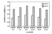
一方、NOx吸蔵性能の測定試験においては、実施例1〜5及び比較例1の各ハニカム触媒に対して、上記HC浄化率測定の場合と同じエージング処理を行なった後、ハニカム触媒をモデルガス流通反応装置に取り付けた。ハニカム触媒に空燃比リッチのモデルガスを流通させた状態で触媒入口ガス温度を200℃に保持し、該温度を保った状態で空燃比リーンのモデルガスに切り替え、このモデルガスの切替えから180秒間のNOx吸蔵量を測定した。また、触媒入口ガス温度を250℃として、同様に空燃比リッチのモデルガスから空燃比リーンのモデルガスに切り替えてから180秒間のNOx吸蔵量を測定した。 On the other hand, in the NOx occlusion performance measurement test, the honeycomb catalyst of Examples 1 to 5 and Comparative Example 1 was subjected to the same aging treatment as in the case of the HC purification rate measurement, and then the honeycomb catalyst was passed through the model gas. Attached to the reactor. The catalyst inlet gas temperature is maintained at 200 ° C. with the air-fuel ratio rich model gas being circulated through the honeycomb catalyst, and is switched to the air-fuel ratio lean model gas while maintaining the temperature, and this model gas is switched for 180 seconds. NOx occlusion amount was measured. Similarly, the NOx occlusion amount was measured for 180 seconds after the catalyst inlet gas temperature was set to 250 ° C. and the air-fuel ratio rich model gas was switched to the air-fuel ratio lean model gas.
リッチモデルガスの組成は、NOが220ppm、HCが3400ppmC、COが1.0%、O2が0.5%、CO2が6%、H2Oが10%、残部がN2である。リーンモデルガスの組成は、NOが220ppm、HCが400ppmC、COが0.15%、O2が10%、CO2が6%、H2Oが10%、残部がN2である。NOx吸蔵性能の測定試験の結果を図6に示す。 The composition of the rich model gas is 220 ppm NO, 3400 ppm HC, 1.0% CO, 0.5% O 2 , 6% CO 2 , 10% H 2 O and the balance N 2 . The composition of the lean model gas is 220 ppm NO, 400 ppm HC, 0.15% CO, 10% O 2 , 6% CO 2 , 10% H 2 O, and the balance N 2 . The results of the NOx storage performance measurement test are shown in FIG.
図6に示すように、実施例1〜5及び比較例1の触媒のNOx吸蔵量をみると、SO2 ガス処理を行うことでNOx吸蔵量が高くなっている。これも、SO2 ガス処理によるNOx吸蔵材の溶出抑制効果によるものと考えられる。また、SO2処理率が9.8%をピークとして、それよりもSO2処理率が高くなるにつれてNOx吸蔵量が低くなっていく傾向が見られる。これは、NOx吸蔵材の硫酸塩化が進みすぎ、その後のCO処理によっても、NOx吸蔵材が完全に炭酸塩にならず、一部が所謂硫黄被毒の状態で残るためであると考えられる。図6に示す結果から、SO2処理率は1%以上50%以下にすることが好ましいということができる。 As shown in FIG. 6, when the NOx occlusion amounts of the catalysts of Examples 1 to 5 and Comparative Example 1 are seen, the NOx occlusion amount is increased by performing the SO 2 gas treatment. This is also considered to be due to the elution suppression effect of the NOx occlusion material by the SO 2 gas treatment. In addition, the SO 2 treatment rate peaks at 9.8%, and the NOx occlusion amount tends to decrease as the SO 2 treatment rate becomes higher than that. This is considered to be because the sulfation of the NOx occlusion material proceeds too much, and the NOx occlusion material does not completely become carbonate even after the subsequent CO treatment, and a part of the NOx occlusion material remains in a so-called sulfur poisoning state. From the results shown in FIG. 6, it can be said that the SO 2 treatment rate is preferably 1% or more and 50% or less.
なお、上記実施例においては、ゼオライトとしてβ−ゼオライトを用いたが、これにかがらずZSM−5を初めとするアルミノシリケート化合物等も用いることが可能である。 In the above examples, β-zeolite is used as the zeolite. However, it is possible to use an aluminosilicate compound such as ZSM-5.
以上の通り、本発明に係る排気ガス浄化用触媒の製造方法を用いると、高い酸化触媒性能及びNOx吸蔵性能の両方を有する触媒を得ることができる。 As described above, when the method for producing an exhaust gas purifying catalyst according to the present invention is used, a catalyst having both high oxidation catalyst performance and NOx storage performance can be obtained.
1 担体(セル壁)
2 DOC(酸化触媒)層
3 LNT(リーンNOxトラップ)層
4 排気ガス通路
1 Carrier (cell wall)
2 DOC (oxidation catalyst)
Claims (2)
担体上に、ゼオライト、アルミナ、Ce含有酸化物及び触媒金属を含み且つ前記NOx吸蔵材を添加していない酸化触媒層を形成する工程と、
アルミナとCe含有酸化物との混合物に、前記NOx吸蔵材と触媒金属とを担持する工程と、
前記担持された混合物にSO 2 ガス処理をすることにより、前記NOx吸蔵材の表層部を硫酸塩化する工程と、
前記SO2ガス処理された混合物をスラリー化し、前記酸化触媒層にコーティングすることによりLNT層を形成する工程と、
前記NOx吸蔵材をCOガスにより炭酸塩化する工程とを備えていることを特徴とする排気ガス浄化用触媒の製造方法。 A method for producing an exhaust gas purification catalyst comprising a NOx storage material made of Ba or Sr and zeolite,
On the carrier, forming zeolite, alumina, an oxidation catalyst layer without addition of Ce-containing oxide and comprises a catalytic metal and the NOx storage material,
To a mixture of alumina and Ce-containing oxide, and a step of carrying the catalyst metal the NOx-absorbing material,
Sulfating the surface layer of the NOx storage material by subjecting the supported mixture to SO 2 gas treatment ;
Slurrying the SO 2 gas treated mixture and coating the oxidation catalyst layer to form an LNT layer;
And a process for carbonating the NOx storage material with CO gas.
Priority Applications (1)
| Application Number | Priority Date | Filing Date | Title |
|---|---|---|---|
| JP2013110769A JP5954259B2 (en) | 2013-05-27 | 2013-05-27 | Method for producing exhaust gas purifying catalyst |
Applications Claiming Priority (1)
| Application Number | Priority Date | Filing Date | Title |
|---|---|---|---|
| JP2013110769A JP5954259B2 (en) | 2013-05-27 | 2013-05-27 | Method for producing exhaust gas purifying catalyst |
Publications (2)
| Publication Number | Publication Date |
|---|---|
| JP2014226651A JP2014226651A (en) | 2014-12-08 |
| JP5954259B2 true JP5954259B2 (en) | 2016-07-20 |
Family
ID=52126981
Family Applications (1)
| Application Number | Title | Priority Date | Filing Date |
|---|---|---|---|
| JP2013110769A Expired - Fee Related JP5954259B2 (en) | 2013-05-27 | 2013-05-27 | Method for producing exhaust gas purifying catalyst |
Country Status (1)
| Country | Link |
|---|---|
| JP (1) | JP5954259B2 (en) |
Families Citing this family (3)
| Publication number | Priority date | Publication date | Assignee | Title |
|---|---|---|---|---|
| JP6311944B2 (en) * | 2016-03-28 | 2018-04-18 | 株式会社豊田中央研究所 | Honeycomb catalyst |
| EP3495634A4 (en) * | 2016-08-04 | 2020-03-11 | N.E. Chemcat Corporation | URAUS SCR SYSTEM COMPATIBLE WITH COLD START |
| GB2560939A (en) * | 2017-03-29 | 2018-10-03 | Johnson Matthey Plc | NOx Adsorber catalyst |
Family Cites Families (7)
| Publication number | Priority date | Publication date | Assignee | Title |
|---|---|---|---|---|
| US4335023A (en) * | 1980-01-24 | 1982-06-15 | Engelhard Corporation | Monolithic catalyst member and support therefor |
| JP3799651B2 (en) * | 1995-04-28 | 2006-07-19 | マツダ株式会社 | Exhaust gas purification catalyst |
| JP3859940B2 (en) * | 1999-08-06 | 2006-12-20 | 日産自動車株式会社 | Exhaust gas purification catalyst and method for producing the same |
| JP2004130269A (en) * | 2002-10-15 | 2004-04-30 | Nissan Motor Co Ltd | Exhaust gas purification catalyst and method for producing the same |
| JP2004321894A (en) * | 2003-04-23 | 2004-11-18 | Nissan Motor Co Ltd | Exhaust gas purification catalyst and method for producing the same |
| JP4706784B2 (en) * | 2008-09-11 | 2011-06-22 | 株式会社デンソー | Hex cell honeycomb structure |
| JP5785406B2 (en) * | 2011-03-18 | 2015-09-30 | 日本碍子株式会社 | Honeycomb structure |
-
2013
- 2013-05-27 JP JP2013110769A patent/JP5954259B2/en not_active Expired - Fee Related
Also Published As
| Publication number | Publication date |
|---|---|
| JP2014226651A (en) | 2014-12-08 |
Similar Documents
| Publication | Publication Date | Title |
|---|---|---|
| JP6206327B2 (en) | Exhaust gas purification catalyst and method for producing the same | |
| KR101868176B1 (en) | Catalyst for gasoline lean burn engines with improved no oxidation activity | |
| US9242242B2 (en) | Catalyst for gasoline lean burn engines with improved NO oxidation activity | |
| US8950174B2 (en) | Catalysts for gasoline lean burn engines with improved NH3-formation activity | |
| CN102083530B (en) | Honeycomb catalyst for purifying exhaust gas discharged from automobile, method for producing the same, and exhaust gas purifying method using the catalyst | |
| EP3277406B1 (en) | Lean nox trap with enhanced high and low temperature performance | |
| JP6236995B2 (en) | Exhaust gas purification catalyst, method for producing the same, and exhaust gas purification method using the same | |
| JP2012518531A (en) | Palladium supported catalyst composite | |
| JP7489761B2 (en) | Ammonia oxidation catalyst device | |
| JP2020515395A (en) | Three-layer NOx adsorber catalyst | |
| KR101855537B1 (en) | Nox storage catalyst with reduced rh loading | |
| JP2024164024A (en) | Exhaust Gas Treatment System for Ultra-Low NOx and Cold Start | |
| JP5391664B2 (en) | Exhaust gas purification catalyst | |
| JP5954259B2 (en) | Method for producing exhaust gas purifying catalyst | |
| JP5994730B2 (en) | Method for producing exhaust gas purifying catalyst | |
| JP5954260B2 (en) | Exhaust gas purification catalyst and method for producing the same | |
| JP7682799B2 (en) | Tunable NOx Adsorbent | |
| JP5949662B2 (en) | Exhaust gas purification catalyst and method for producing the same | |
| JP6569637B2 (en) | Exhaust gas purification device for internal combustion engine | |
| JP6102699B2 (en) | Method for producing exhaust gas purifying catalyst |
Legal Events
| Date | Code | Title | Description |
|---|---|---|---|
| A621 | Written request for application examination |
Free format text: JAPANESE INTERMEDIATE CODE: A621 Effective date: 20150312 |
|
| A977 | Report on retrieval |
Free format text: JAPANESE INTERMEDIATE CODE: A971007 Effective date: 20160210 |
|
| A131 | Notification of reasons for refusal |
Free format text: JAPANESE INTERMEDIATE CODE: A131 Effective date: 20160216 |
|
| A521 | Request for written amendment filed |
Free format text: JAPANESE INTERMEDIATE CODE: A523 Effective date: 20160415 |
|
| TRDD | Decision of grant or rejection written | ||
| A01 | Written decision to grant a patent or to grant a registration (utility model) |
Free format text: JAPANESE INTERMEDIATE CODE: A01 Effective date: 20160517 |
|
| A61 | First payment of annual fees (during grant procedure) |
Free format text: JAPANESE INTERMEDIATE CODE: A61 Effective date: 20160530 |
|
| R150 | Certificate of patent or registration of utility model |
Ref document number: 5954259 Country of ref document: JP Free format text: JAPANESE INTERMEDIATE CODE: R150 |
|
| LAPS | Cancellation because of no payment of annual fees |