JP5953761B2 - Light emitting device support mechanism - Google Patents
Light emitting device support mechanism Download PDFInfo
- Publication number
- JP5953761B2 JP5953761B2 JP2012008474A JP2012008474A JP5953761B2 JP 5953761 B2 JP5953761 B2 JP 5953761B2 JP 2012008474 A JP2012008474 A JP 2012008474A JP 2012008474 A JP2012008474 A JP 2012008474A JP 5953761 B2 JP5953761 B2 JP 5953761B2
- Authority
- JP
- Japan
- Prior art keywords
- light emitting
- arm
- emitting unit
- camera body
- support
- Prior art date
- Legal status (The legal status is an assumption and is not a legal conclusion. Google has not performed a legal analysis and makes no representation as to the accuracy of the status listed.)
- Expired - Fee Related
Links
Images


Description
本発明は、例えばレンズ交換式カメラのカメラ本体に設けられる発光装置に関し、より詳しくは発光装置とカメラ本体を接続する支持機構に関する。 The present invention relates to a light emitting device provided in, for example, a camera body of an interchangeable lens camera, and more particularly to a support mechanism that connects the light emitting device and the camera body.
従来レンズ交換式カメラの発光装置は、不使用時にはカメラ本体内に収納され、使用時にはカメラ本体からポップアップするように構成されている。発光装置のポップアップ高さは、カメラ本体から前方に突出する撮影レンズによって発光装置からの照明光が遮られる、いわゆるケラレが生じることがないよう、できるだけ大きいことが好ましい。カメラ本体に対してポップアップするように連結された発光装置として、例えば特許文献1、2に開示されたものが知られている。 Conventionally, the light emitting device of the interchangeable lens camera is configured to be housed in the camera body when not in use and to pop up from the camera body when in use. The pop-up height of the light emitting device is preferably as large as possible so that the illuminating light from the light emitting device is not blocked by the photographing lens protruding forward from the camera body. As light emitting devices connected so as to pop up with respect to the camera body, for example, those disclosed in Patent Documents 1 and 2 are known.
特許文献1に開示された発光装置のポップアップ機構によると、コンパクトカメラのように撮影レンズの突出量がそれほど大きくないカメラの場合は問題ないが、撮影レンズの突出量が大きいカメラではポップアップの量が不十分になるという問題が発生する。一方特許文献2に開示された発光装置のポップアップ機構によると、ポップアップの量は十分であるが、カメラ本体への収納が考慮されていない。 According to the pop-up mechanism of the light emitting device disclosed in Patent Document 1, there is no problem in the case of a camera in which the projection amount of the photographing lens is not so large, such as a compact camera. The problem of becoming insufficient occurs. On the other hand, according to the pop-up mechanism of the light emitting device disclosed in Patent Document 2, the amount of pop-up is sufficient, but storage in the camera body is not considered.
本発明は、撮影レンズのカメラ本体からの突出量が大きいレンズ交換式カメラにおいても、ポップアップの高さを十分に大きくすることができ、しかもカメラ本体内にコンパクトに収納することができる発光装置の支持機構を提供することを目的としている。 The present invention provides a light emitting device capable of sufficiently increasing the height of a pop-up even in an interchangeable lens camera having a large projection amount of a photographing lens from the camera body, and capable of being compactly accommodated in the camera body. It aims to provide a support mechanism.
本発明に係る発光装置の支持機構は、カメラ本体に、第1支持部において枢支された第1のアームと、第1のアームの端部に、第1の支持部とは異なる第2支持部において回動自在に連結された連結部材と、連結部材において、第2支持部とは異なる第3支持部において回動自在に連結され、発光部を有する発光ユニットが取付けられた発光ユニット支持部材とを備え、第1のアームと連結部材と発光ユニット支持部材とをカメラ本体の収納凹部に収納した状態において、第1のアームと発光ユニット支持部材が相互に平行状態になり、発光部が第1支持部に近接することを特徴としている。 The light emitting device support mechanism according to the present invention includes a camera body, a first arm pivotally supported by the first support portion, and a second support different from the first support portion at the end of the first arm. And a light-emitting unit support member attached to a light-emitting unit having a light-emitting part, which is rotatably connected to a third support part different from the second support part. And the first arm, the connecting member, and the light emitting unit support member are housed in the housing recess of the camera body, the first arm and the light emitting unit support member are parallel to each other, and the light emitting unit is It is characterized by being close to one support part.
発光装置の支持機構は、カメラ本体に、第1支持部とは異なる第4支持部において枢支された第2のアームを備え、第2のアームの端部が第3支持部に連結されることが好ましい。この構成において、さらに、第3支持部にバネが設けられ、バネの一方の端部が発光ユニット支持部材に係止するとともに、バネの他方の端部が第2のアームに係止するように構成されてもよい。この構成では、発光ユニット支持部材と第2のアームは、成す角が180度に近づく方向に付勢され、これにより発光装置は自動的にポップアップする。また第1および第2のアームと連結部材と発光ユニットとをカメラ本体の収納凹部に収納した状態において、第2のアームと発光ユニットが相互に平行状態になることが好ましい。 The support mechanism of the light emitting device includes a camera body including a second arm pivotally supported by a fourth support portion different from the first support portion, and an end portion of the second arm is coupled to the third support portion. It is preferable. In this configuration, the third support portion is further provided with a spring, and one end of the spring is locked to the light emitting unit support member, and the other end of the spring is locked to the second arm. It may be configured. In this configuration, the light emitting unit support member and the second arm are urged in a direction in which the angle formed approaches 180 degrees, and thereby the light emitting device automatically pops up. In the state where the first and second arms, the connecting member, and the light emitting unit are housed in the housing recess of the camera body, it is preferable that the second arm and the light emitting unit are parallel to each other.
発光装置の支持機構は、カメラ本体に変位自在に設けられ、第1のアームと連結部材と発光ユニット支持部材とを収納凹部に収納した状態において発光ユニット支持部材に係合可能な係止爪と、カメラ本体内に配設され、係止爪を変位させるための係止爪駆動部と、カメラ本体を前面側から見たときに、第1のアームと連結部材と係止爪と係止爪駆動部とが発光部の幅の中に収まるように構成されてもよい。これによれば、発光装置が全体的にコンパクトになる。 The support mechanism of the light emitting device is provided on the camera body so as to be displaceable, and a locking claw that can be engaged with the light emitting unit support member in a state where the first arm, the connecting member, and the light emitting unit support member are stored in the storage recess. , A locking claw driving unit disposed in the camera body for displacing the locking claw, and the first arm, the connecting member, the locking claw, and the locking claw when the camera body is viewed from the front side. The drive unit may be configured to fit within the width of the light emitting unit. According to this, the light emitting device becomes compact as a whole.
また、カメラ本体の前面にレンズ鏡筒を装着するための円形のレンズマウントが形成されるとともに、カメラ本体の背面側に、レンズマウントの中央部に中心が位置するようにして矩形の撮像素子が配置され、収納凹部の内側底面が、レンズマウントの上側縁部の下縁と撮像素子の撮像領域の上辺との間に位置することが好ましい。 In addition, a circular lens mount for mounting the lens barrel is formed on the front surface of the camera body, and a rectangular imaging device is arranged on the back side of the camera body so that the center is located at the center of the lens mount. It is preferable that the inner bottom surface of the storage recess is located between the lower edge of the upper edge of the lens mount and the upper side of the imaging area of the imaging device.
また本発明に係る第2の発光装置の支持機構は、カメラ本体に、第1支持部において枢支された第1のアームと、第1のアームの端部に、第1支持部とは異なる第2支持部において回動自在に連結された連結部材と、連結部材において、第2支持部とは異なる第3支持部において回動自在に連結され、発光部を有する発光ユニットとを備え、第1のアームと連結部材と発光ユニットとをカメラ本体の収納凹部に収納した状態において、第1のアームと連結部材と発光ユニットとがカメラ本体の横方向から見てコの字状を呈することを特徴としている。 Further, the second light emitting device support mechanism according to the present invention is different from the first support portion at the end of the first arm and the first arm pivotally supported by the camera body at the first support portion. A connecting member rotatably connected to the second support portion; and a light-emitting unit having a light-emitting portion connected rotatably to a third support portion different from the second support portion in the connecting member; The first arm, the connecting member, and the light emitting unit have a U-shape when viewed from the side of the camera body in a state where the one arm, the connecting member, and the light emitting unit are stored in the storage recess of the camera body. It is a feature.
本発明によれば、撮影レンズのカメラ本体からの突出量が大きいカメラにおいても、発光装置のポップアップの高さを十分に大きくすることができ、しかもカメラ本体内にコンパクトに収納することができるという効果が得られる。 According to the present invention, the height of the pop-up of the light emitting device can be sufficiently increased even in a camera having a large amount of projection of the photographing lens from the camera body, and can be stored compactly in the camera body. An effect is obtained.
以下、本発明の一実施形態を図面を参照して説明する。
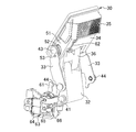
図1はレンズ交換式カメラの外観を示し、カメラ本体10からレンズ鏡筒を外した状態を示している。このカメラはいわゆるミラーレスタイプであり、光学ファインダは設けられておらず、被写体像はカメラ本体10の背面に設けられたモニタに表示される。カメラ本体10の上面には、撮影モード等を選択するためのモードダイアル11が設けられ、モードダイアル11の横には発光装置30が設けられる。またカメラ本体10の上面には、発光装置30をポップアップさせるための発光ボタン39(図3参照)が設けられる。なお図1において発光装置30はカメラ本体10内に収納された状態にある。
Hereinafter, an embodiment of the present invention will be described with reference to the drawings.
FIG. 1 shows the appearance of an interchangeable lens camera, and shows a state in which the lens barrel is removed from the
カメラ本体10の前面には、レンズ鏡筒を装着するためのレンズマウント12が形成される。レンズマウント12は円形を呈し、カメラ本体10を正面から見ると光学装置30の真下に位置する。レンズマウント12には、カメラ本体10内の制御システムとレンズ鏡筒内の制御システムとの間においてデータ通信等を行うための接点13、レンズ鏡筒を取付けるための爪14等が設けられる。
A
図2はカメラ本体の中の構造の一部を抜き出して示すものである。レンズマウント12は暗箱15の前面に固定される。暗箱15の上部には、発光装置30が出没自在に取付けられる収納凹部16が形成される。カメラ本体の背面側には撮像素子17が設けられ、撮像素子17と暗箱15の間にはシャッタ18が設けられる。撮像素子17の前面に設けられる撮像領域17aはカバーガラス19により覆われる。図3に示すように撮像領域17aは、カメラ本体を正面から見ると矩形を呈し、撮像素子17はレンズマウント12の中央部に受光面19の中心が位置するようにして配置される。また収納凹部16の幅はレンズマウント12の幅よりも小さい。
FIG. 2 shows a part of the structure inside the camera body. The
本実施形態において収納凹部16はレンズマウント12の上部に形成され、発光装置30の上面31がカメラ本体の上面から突出する量が極力小さくなるよう、できるだけ下方に位置するように考慮されている。すなわちレンズマウント12の上端12aを基準として見た場合に、上端12aから収納凹部16の内側底面25までの高さは、上端12aから発光装置30の上面31までの高さよりも大きい。収納凹部16の内側底面25は、図2に示すようにレンズマウント12の上側縁部21に設けられた係合爪の下縁21aと撮像領域17aの上辺22との間に位置し、また収納凹部16の前端面23はレンズマウント12よりもカメラ本体の背面側に位置する。すなわち収納凹部16および収納状態にある発光装置30の全てがレンズマウント12よりも背面側に位置する。
In the present embodiment, the
このように収納凹部16は、下端部20が撮影レンズからの入射光に干渉しない限度において最下位置に設けられており、これにより発光装置30の上面31はカメラ本体10の上面に設けられた発光装置30以外の部材(本実施形態ではモードダイアル11)と略同じ高さにあり、この部材よりも大きく突出することはない。また撮像レンズの設計に応じて、収納凹部16の下端部20をさらに下方に定めることができ、下端部20が撮像領域17aの上辺22にできるだけ近づくように、収納凹部16の内側底面25を下方に位置させればよい。
As described above, the
図2から理解されるように、収納状態にある発光装置30の高さ、すなわち内側底面25から上面31までの高さは、暗箱15の高さよりも小さく、発光装置30はコンパクトに折り畳まれて収納凹部16に収納される。
As understood from FIG. 2, the height of the
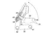
図4は発光装置30がポップアップした状態を示している。発光装置30は第1のアーム32と第2のアーム33によってカメラ本体に回動自在に支持されており、これらのアーム32、33が図2の収納状態から立ち上がることによって発光ユニット34がポップアップする。ポップアップ状態において、第1のアーム32は収納凹部16の底面に対して略垂直であり、第2のアーム33は第1のアーム32よりも撮像素子17側に傾斜しており、発光ユニット34の発光部35の前面はレンズマウント12の面に略平行である。
FIG. 4 shows a state where the
再び図2を参照すると、収納状態、すなわち第1および第2のアーム32、33と連結部材36と発光ユニット34を収納凹部16に収納した状態において、第1および第2のアーム32、33と発光ユニット34は相互に平行であり、発光部35は、後述するピン41に近接しており、また第1のアーム32と発光ユニット34を連結する連結部材36は、アーム32と33と発光ユニット34に対して略垂直である。すなわち発光装置30は収納状態においてカメラ本体の横方向から見てコの字状を呈する。
Referring again to FIG. 2, the first and
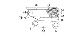
図5、6、7を参照して発光装置30のカメラ本体に対する支持機構の構成を説明する。第1のアーム32は第1支持部であるピン41によってカメラ本体に枢支される。連結部材36は第1のアーム32の先端に、第2支持部であるピン42によって回動自在に連結される。発光ユニット34は連結部材36において、ピン42とは反対側の端部に位置する第3支持部のピン43に回動自在に連結される。第2のアーム33は第1支持部のピン41とは異なる第4支持部であるピン44によってカメラ本体に枢支される。第2アーム33の先端は第3支持部のピン43に連結される。このように、第1および第2のアーム32、33と連結部材36とピン41〜44によってリンク機構が構成される。
The structure of the support mechanism for the camera body of the
発光ユニット34の側壁51には円弧状のスリット52が形成される。第2のアーム33のピン43に近接した部位には係合ピン53が固定され、係合ピン53は円弧状スリット52に係合する。発光ユニット34は係合ピン53が円弧状スリット52に係合する範囲内において第2のアーム33に対して回動自在である。すなわち係合ピン53は、図2の収納状態では円弧状スリット52の一方の端部に係止し、図4のポップアップ状態では円弧状スリット52の他方の端部に係止する。
An arc-shaped
ピン43にはコイルバネであるポップアップバネ54が設けられる。バネ54の一方の端部は発光ユニット34に係止し、他方の端部は係合ピン53すなわち第2のアーム33に係止する(図8、10参照)。バネ54により、発光ユニット34と第2のアーム33は、これらの成す角が180度に近づく方向に常時付勢される。例えば図2に示す収納状態では、発光ユニット34と第2のアーム33の成す角は略0度であり、発光ユニット34はピン43を中心として第2のアーム33から離れる方向に回動する方向に付勢される。また図4に示すポップアップ状態では、発光ユニット34は第2のアーム33と成す角がより大きくなる方向に付勢されるが、係合ピン53が円弧状スリット52の端部に係止するため、発光ユニット34と第2のアーム33の成す角はこれ以上大きくならない。
The
カメラ本体の上面であって収納凹部16の側方には、係止爪61が設けられる。係止爪61はカメラ本体10の前後方向、すなわち第1および第2のアーム32、33が回動する面に平行な面に沿って変位自在であり、第1および第2のアーム32、33と連結部材36と発光ユニット34とを収納凹部16に収納した状態(図2に示す収納状態)において発光ユニット34に係合可能である。発光ユニット34の下面には、係止爪61が係合するための溝62が形成される。
A locking
カメラ本体10内には係止爪61を変位させるための係止爪駆動部63が配設される。係止爪駆動部63は電磁石64と可動部材65と係止バネ66とを有する。係止爪61は、図示しない支点の周りに回動自在であり、可動部材65は支点を挟んで係止爪61とは反対側の揺動部に連結される。係止爪61は係止バネ66によってカメラ本体10の前方(図7の右方)に付勢される。可動部材65は電磁石64が通電されたとき、図7の右方に突出し、この突出動作に連動して係止バネ66の付勢力により係止爪61が図7の左方に後退する。すなわち図2に示す収納状態では、係止爪61は溝62に係合し、これにより発光ユニット34は収納状態に保持されるが、発光ボタン39が押されて電磁石64が通電されると、係止爪61が後退して溝62を解放し、発光ユニット34がポップアップする。
A locking
図6から理解されるように、カメラ本体を前面側から見たときに、第1のアーム32と連結部材36と係止爪駆動部63とが発光部35の幅の中に収まるように構成されている。第1のアーム32と連結部材36の中はそれぞれ、発光ユニット34と図示しない電子回路を電気的に接続するリード線が収納されており、第1のアーム32と連結部材36のピン41の軸方向に沿う長さは発光部35の幅よりも小さく、第1のアーム32と第2のアーム33との間に形成されるスペースに、係止爪駆動部63と係止爪61が配置されている。
As can be understood from FIG. 6, the
図8〜11を参照して、本実施形態において採用されているポップアップ機構の構成と作用を説明する。
連結部材36を貫通して延びる第3支持部のピン43には、上述したようにポップアップバネ54が設けられる。また連結部材36には、円板の一部を径方向の外側に膨出させて形成されたストッパ71が形成される。ストッパ71は発光ユニット34に形成された当接面72に当接可能である。一方第2のアーム33は、ピン44の近傍において第3支持部のピン43とは反対方向に延びる突起73を有する。この突起73はカメラ本体に固定されたストッパピン74に係合可能である。
With reference to FIGS. 8-11, the structure and effect | action of the pop-up mechanism employ | adopted in this embodiment are demonstrated.
As described above, the pop-up
発光装置の収納状態では、図8、9に示すように、発光ユニット34と第2のアーム33の成す角は略0度である。また発光ユニット34は連結部材36に対して略垂直であり、ストッパ71は当接面72から離間している。この状態において係止爪61が後退して発光ユニット34を解放すると、バネ54の付勢力により、発光ユニット34は連結部材36に対して回動するように作用し、図10、11に示すように発光ユニット34は連結部材36に対して起き上がる。発光ユニット34の当接面72にストッパ71が当接すると、発光ユニット34は連結部材36に対して回動しなくなり、発光ユニット34と第2のアーム33はバネ54の付勢力により、これらの成す角が大きくなるように変化する。すなわち、図12に示すように第2のアーム33がピン44を中心に回動して起き上がり、突起73がストッパピン74に係合した位置において静止する。
In the housed state of the light emitting device, as shown in FIGS. 8 and 9, the angle formed by the
以上のように本実施形態の発光装置30の支持機構は、第1のアーム32に連結部材36を介して発光ユニット34を連結したので、発光ユニット34のポップアップ高さが十分に大きくなり、したがって、カメラ本体10に装着された撮影レンズの突出量が大きくてもケラレが発生することが防止される。
As described above, since the support mechanism of the
また、発光ユニット34が収納状態にあるとき、発光装置30は全体的にコの字状になるように折り畳まれるので、収納凹部16内にコンパクトに収納される。さらに、収納凹部16の内側底面25はレンズマウント12の上側縁部21と撮像素子17の受光面19の上辺22との間に位置し、また収納凹部16の前端面23がレンズマウント12よりもカメラ本体の背面側に位置している。したがって、収納凹部16を極力下方に配置することができ、発光装置30の上面31のカメラ本体10の上面からの突出量を小さく抑えることができる。
Further, when the
なお、上記実施形態では、ポップアップバネ54はピン43のみに設けられていたが、これに代えて、バネを、ピン41、42に設けるとともに、発光ユニット34と連結部材36の間に設けてもよく、このような構成によると第2のアーム33を省略することができる。
In the above embodiment, the pop-up
なお発光ユニット34は電磁石64を設けるのではなく、発光ボタン39を押すと機械的に係止爪61が外れるように構成されてもよい。
The
10 カメラ本体
16 収納凹部
32 第1のアーム
34 発光ユニット
36 連結部材
41 ピン(第1支持部)
42 ピン(第2支持部)
43 ピン(第3支持部)
44 ピン(第4支持部)
DESCRIPTION OF
42 pin (second support part)
43 pin (3rd support part)
44 pins (4th support part)
Claims (5)
前記第1のアームの端部に、前記第1支持部とは異なる第2支持部において回動自在に連結された連結部材と、
前記連結部材において、前記第2支持部とは異なる第3支持部において回動自在に連結され、発光部を有する発光ユニットとを備え、
前記第1のアームと前記連結部材と前記発光ユニットとを前記カメラ本体の収納凹部に収納した状態において、前記第1のアームと前記発光ユニットが相互に対向した状態になり、前記発光部が前記第1支持部に近接し、
前記カメラ本体に、前記第1支持部とは異なる第4支持部において枢支された第2のアームを備え、前記第2のアームの端部は前記第3支持部に連結され、
前記第3支持部にバネが設けられ、前記バネの一方の端部が前記発光ユニットに係止するとともに、前記バネの他方の端部が前記第2のアームに係止し、前記発光ユニットと前記第2のアームは、成す角が180度に近づく方向に付勢される
ことを特徴とする発光装置の支持機構。 A first arm pivotally supported by a first support on the camera body;
A connecting member rotatably connected to an end portion of the first arm in a second support portion different from the first support portion;
A light-emitting unit having a light-emitting unit that is rotatably connected to a third support unit different from the second support unit in the connection member;
In a state in which the said first arm and the connecting member and the light emitting unit housed in the housing recess of the camera body, ready for the first arm and the light-emitting unit is opposed to each other, the light emitting portion is the Close to the first support ,
The camera body includes a second arm pivotally supported by a fourth support portion different from the first support portion, and an end portion of the second arm is connected to the third support portion,
A spring is provided in the third support portion, and one end portion of the spring is engaged with the light emitting unit, and the other end portion of the spring is engaged with the second arm, The light emitting device support mechanism, wherein the second arm is biased in a direction in which an angle formed approaches 180 degrees .
前記カメラ本体内に配設され、前記係止爪を変位させるための係止爪駆動部とを備え、
前記カメラ本体を前面側から見たときに、前記第1のアームと前記連結部材と前記係止爪と前記係止爪駆動部とが前記発光部の幅の中に収まることを特徴とする請求項1に記載の発光装置の支持機構。 A locking claw that is displaceably provided on the camera body, and is engageable with the light emitting unit in a state where the first arm, the connecting member, and the light emitting unit are housed in the housing recess;
Said camera is disposed in the main body, and a locking pawl driver for displacing the locking claw,
The first arm, the connecting member, the locking claw, and the locking claw driving unit are within the width of the light emitting unit when the camera body is viewed from the front side. Item 4. A support mechanism for a light-emitting device according to Item 1.
前記第1のアームの端部に、前記第1支持部とは異なる第2支持部において回動自在に連結された連結部材と、
前記連結部材において、前記第2支持部とは異なる第3支持部において回動自在に連結され、発光部を有する発光ユニットとを備え、
前記第1のアームと前記連結部材と前記発光ユニットとを前記カメラ本体の収納凹部に収納した状態において、前記第1のアームと前記連結部材と前記発光ユニットとがカメラ本体の横方向から見てコの字状を呈し、
前記カメラ本体に、前記第1支持部とは異なる第4支持部において枢支された第2のアームを備え、前記第2のアームの端部は前記第3支持部に連結され、
前記第3支持部にバネが設けられ、前記バネの一方の端部が前記発光ユニットに係止するとともに、前記バネの他方の端部が前記第2のアームに係止し、前記発光ユニットと前記第2のアームは、成す角が180度に近づく方向に付勢される
ことを特徴とする発光装置の支持機構。
A first arm pivotally supported by a first support on the camera body;
A connecting member rotatably connected to an end portion of the first arm in a second support portion different from the first support portion;
A light-emitting unit having a light-emitting unit that is rotatably connected to a third support unit different from the second support unit in the connection member;
When the first arm, the connecting member, and the light emitting unit are housed in the housing recess of the camera body, the first arm, the connecting member, and the light emitting unit are viewed from the side of the camera body. and coloration of the U-shape,
The camera body includes a second arm pivotally supported by a fourth support portion different from the first support portion, and an end portion of the second arm is connected to the third support portion,
A spring is provided in the third support portion, and one end portion of the spring is engaged with the light emitting unit, and the other end portion of the spring is engaged with the second arm, The light emitting device support mechanism, wherein the second arm is biased in a direction in which an angle formed approaches 180 degrees .
Priority Applications (3)
| Application Number | Priority Date | Filing Date | Title |
|---|---|---|---|
| JP2012008474A JP5953761B2 (en) | 2012-01-18 | 2012-01-18 | Light emitting device support mechanism |
| US13/738,252 US8827471B2 (en) | 2012-01-18 | 2013-01-10 | Storage structure and support mechanism for light emitting device |
| CN201320025742.0U CN203101789U (en) | 2012-01-18 | 2013-01-17 | Storage structure applied to light emitting device and support mechanism |
Applications Claiming Priority (1)
| Application Number | Priority Date | Filing Date | Title |
|---|---|---|---|
| JP2012008474A JP5953761B2 (en) | 2012-01-18 | 2012-01-18 | Light emitting device support mechanism |
Publications (2)
| Publication Number | Publication Date |
|---|---|
| JP2013148680A JP2013148680A (en) | 2013-08-01 |
| JP5953761B2 true JP5953761B2 (en) | 2016-07-20 |
Family
ID=49046254
Family Applications (1)
| Application Number | Title | Priority Date | Filing Date |
|---|---|---|---|
| JP2012008474A Expired - Fee Related JP5953761B2 (en) | 2012-01-18 | 2012-01-18 | Light emitting device support mechanism |
Country Status (1)
| Country | Link |
|---|---|
| JP (1) | JP5953761B2 (en) |
Families Citing this family (1)
| Publication number | Priority date | Publication date | Assignee | Title |
|---|---|---|---|---|
| WO2020145134A1 (en) * | 2019-01-11 | 2020-07-16 | ソニー株式会社 | Imaging device |
Family Cites Families (9)
| Publication number | Priority date | Publication date | Assignee | Title |
|---|---|---|---|---|
| JPS63173029A (en) * | 1987-01-13 | 1988-07-16 | Asahi Optical Co Ltd | Mechanism for locking pop-up device of built-in flash |
| JPH0854669A (en) * | 1994-06-06 | 1996-02-27 | Nikon Corp | Flash system |
| JP3728044B2 (en) * | 1997-02-14 | 2005-12-21 | ペンタックス株式会社 | Camera with built-in flash |
| JPH11183976A (en) * | 1997-12-18 | 1999-07-09 | Olympus Optical Co Ltd | Camera |
| JP2001051325A (en) * | 1999-08-09 | 2001-02-23 | Olympus Optical Co Ltd | Camera provided with stroboscopic light emission device |
| JP2004126417A (en) * | 2002-10-07 | 2004-04-22 | Fuji Photo Film Co Ltd | Camera |
| JP4434656B2 (en) * | 2002-10-09 | 2010-03-17 | パナソニック株式会社 | Camera with built-in flash |
| CN2874552Y (en) * | 2006-01-19 | 2007-02-28 | 坤联(厦门)照相器材有限公司 | Flash lamp open and close structure |
| US8373795B2 (en) * | 2008-09-10 | 2013-02-12 | Panasonic Corporation | Camera body and imaging device to which a lens unit configured to form an optical image of a subject can be mounted |
-
2012
- 2012-01-18 JP JP2012008474A patent/JP5953761B2/en not_active Expired - Fee Related
Also Published As
| Publication number | Publication date |
|---|---|
| JP2013148680A (en) | 2013-08-01 |
Similar Documents
| Publication | Publication Date | Title |
|---|---|---|
| US8827471B2 (en) | Storage structure and support mechanism for light emitting device | |
| JP5688541B2 (en) | Imaging device | |
| JP6575513B2 (en) | Imaging device | |
| JP2011013641A (en) | Movement mechanism of movable member, and imaging apparatus | |
| JP5574728B2 (en) | Imaging device | |
| JP5691829B2 (en) | Built-in flash pop-up mechanism of the camera | |
| JP5526101B2 (en) | Imaging device | |
| JP5953761B2 (en) | Light emitting device support mechanism | |
| JP2010186633A (en) | Electronic device | |
| JP6069838B2 (en) | Light-emitting device storage structure | |
| JP5566123B2 (en) | Imaging device | |
| JP2005354177A (en) | Camera | |
| JP5532704B2 (en) | Lighting device for photography | |
| JP5217252B2 (en) | Strobe built-in camera and camera external unit | |
| US10057472B2 (en) | Flash unit having movable light emitting unit and image pickup apparatus equipped with flash unit | |
| JP2014182214A (en) | Accessory | |
| JP6494225B2 (en) | Imaging device | |
| JP2013130699A (en) | Electronic apparatus | |
| JP2006323029A (en) | Camera | |
| JP6128949B2 (en) | Imaging device | |
| JP7098410B2 (en) | Electronics | |
| JP2009015172A (en) | External finder device and imaging device having it | |
| JP2016109706A (en) | Imaging device | |
| JP6750846B2 (en) | Light emitting device and imaging device | |
| JP4626162B2 (en) | camera |
Legal Events
| Date | Code | Title | Description |
|---|---|---|---|
| A621 | Written request for application examination |
Free format text: JAPANESE INTERMEDIATE CODE: A621 Effective date: 20141126 |
|
| RD05 | Notification of revocation of power of attorney |
Free format text: JAPANESE INTERMEDIATE CODE: A7425 Effective date: 20150327 |
|
| A977 | Report on retrieval |
Free format text: JAPANESE INTERMEDIATE CODE: A971007 Effective date: 20151021 |
|
| A131 | Notification of reasons for refusal |
Free format text: JAPANESE INTERMEDIATE CODE: A131 Effective date: 20151027 |
|
| A521 | Written amendment |
Free format text: JAPANESE INTERMEDIATE CODE: A523 Effective date: 20151218 |
|
| TRDD | Decision of grant or rejection written | ||
| A01 | Written decision to grant a patent or to grant a registration (utility model) |
Free format text: JAPANESE INTERMEDIATE CODE: A01 Effective date: 20160517 |
|
| A61 | First payment of annual fees (during grant procedure) |
Free format text: JAPANESE INTERMEDIATE CODE: A61 Effective date: 20160530 |
|
| R150 | Certificate of patent or registration of utility model |
Ref document number: 5953761 Country of ref document: JP Free format text: JAPANESE INTERMEDIATE CODE: R150 |
|
| LAPS | Cancellation because of no payment of annual fees |