JP5953423B2 - Generator / motor unit, power output engine, and vehicle - Google Patents
Generator / motor unit, power output engine, and vehicle Download PDFInfo
- Publication number
- JP5953423B2 JP5953423B2 JP2015504134A JP2015504134A JP5953423B2 JP 5953423 B2 JP5953423 B2 JP 5953423B2 JP 2015504134 A JP2015504134 A JP 2015504134A JP 2015504134 A JP2015504134 A JP 2015504134A JP 5953423 B2 JP5953423 B2 JP 5953423B2
- Authority
- JP
- Japan
- Prior art keywords
- stator
- rotor
- cylindrical member
- magnetic flux
- power output
- Prior art date
- Legal status (The legal status is an assumption and is not a legal conclusion. Google has not performed a legal analysis and makes no representation as to the accuracy of the status listed.)
- Active
Links
Images


Classifications
-
- B—PERFORMING OPERATIONS; TRANSPORTING
- B60—VEHICLES IN GENERAL
- B60W—CONJOINT CONTROL OF VEHICLE SUB-UNITS OF DIFFERENT TYPE OR DIFFERENT FUNCTION; CONTROL SYSTEMS SPECIALLY ADAPTED FOR HYBRID VEHICLES; ROAD VEHICLE DRIVE CONTROL SYSTEMS FOR PURPOSES NOT RELATED TO THE CONTROL OF A PARTICULAR SUB-UNIT
- B60W20/00—Control systems specially adapted for hybrid vehicles
- B60W20/10—Controlling the power contribution of each of the prime movers to meet required power demand
- B60W20/15—Control strategies specially adapted for achieving a particular effect
- B60W20/19—Control strategies specially adapted for achieving a particular effect for achieving enhanced acceleration
-
- B—PERFORMING OPERATIONS; TRANSPORTING
- B60—VEHICLES IN GENERAL
- B60K—ARRANGEMENT OR MOUNTING OF PROPULSION UNITS OR OF TRANSMISSIONS IN VEHICLES; ARRANGEMENT OR MOUNTING OF PLURAL DIVERSE PRIME-MOVERS IN VEHICLES; AUXILIARY DRIVES FOR VEHICLES; INSTRUMENTATION OR DASHBOARDS FOR VEHICLES; ARRANGEMENTS IN CONNECTION WITH COOLING, AIR INTAKE, GAS EXHAUST OR FUEL SUPPLY OF PROPULSION UNITS IN VEHICLES
- B60K6/00—Arrangement or mounting of plural diverse prime-movers for mutual or common propulsion, e.g. hybrid propulsion systems comprising electric motors and internal combustion engines ; Control systems therefor, i.e. systems controlling two or more prime movers, or controlling one of these prime movers and any of the transmission, drive or drive units Informative references: mechanical gearings with secondary electric drive F16H3/72; arrangements for handling mechanical energy structurally associated with the dynamo-electric machine H02K7/00; machines comprising structurally interrelated motor and generator parts H02K51/00; dynamo-electric machines not otherwise provided for in H02K see H02K99/00
- B60K6/20—Arrangement or mounting of plural diverse prime-movers for mutual or common propulsion, e.g. hybrid propulsion systems comprising electric motors and internal combustion engines ; Control systems therefor, i.e. systems controlling two or more prime movers, or controlling one of these prime movers and any of the transmission, drive or drive units Informative references: mechanical gearings with secondary electric drive F16H3/72; arrangements for handling mechanical energy structurally associated with the dynamo-electric machine H02K7/00; machines comprising structurally interrelated motor and generator parts H02K51/00; dynamo-electric machines not otherwise provided for in H02K see H02K99/00 the prime-movers consisting of electric motors and internal combustion engines, e.g. HEVs
- B60K6/22—Arrangement or mounting of plural diverse prime-movers for mutual or common propulsion, e.g. hybrid propulsion systems comprising electric motors and internal combustion engines ; Control systems therefor, i.e. systems controlling two or more prime movers, or controlling one of these prime movers and any of the transmission, drive or drive units Informative references: mechanical gearings with secondary electric drive F16H3/72; arrangements for handling mechanical energy structurally associated with the dynamo-electric machine H02K7/00; machines comprising structurally interrelated motor and generator parts H02K51/00; dynamo-electric machines not otherwise provided for in H02K see H02K99/00 the prime-movers consisting of electric motors and internal combustion engines, e.g. HEVs characterised by apparatus, components or means specially adapted for HEVs
- B60K6/26—Arrangement or mounting of plural diverse prime-movers for mutual or common propulsion, e.g. hybrid propulsion systems comprising electric motors and internal combustion engines ; Control systems therefor, i.e. systems controlling two or more prime movers, or controlling one of these prime movers and any of the transmission, drive or drive units Informative references: mechanical gearings with secondary electric drive F16H3/72; arrangements for handling mechanical energy structurally associated with the dynamo-electric machine H02K7/00; machines comprising structurally interrelated motor and generator parts H02K51/00; dynamo-electric machines not otherwise provided for in H02K see H02K99/00 the prime-movers consisting of electric motors and internal combustion engines, e.g. HEVs characterised by apparatus, components or means specially adapted for HEVs characterised by the motors or the generators
-
- B—PERFORMING OPERATIONS; TRANSPORTING
- B60—VEHICLES IN GENERAL
- B60K—ARRANGEMENT OR MOUNTING OF PROPULSION UNITS OR OF TRANSMISSIONS IN VEHICLES; ARRANGEMENT OR MOUNTING OF PLURAL DIVERSE PRIME-MOVERS IN VEHICLES; AUXILIARY DRIVES FOR VEHICLES; INSTRUMENTATION OR DASHBOARDS FOR VEHICLES; ARRANGEMENTS IN CONNECTION WITH COOLING, AIR INTAKE, GAS EXHAUST OR FUEL SUPPLY OF PROPULSION UNITS IN VEHICLES
- B60K6/00—Arrangement or mounting of plural diverse prime-movers for mutual or common propulsion, e.g. hybrid propulsion systems comprising electric motors and internal combustion engines ; Control systems therefor, i.e. systems controlling two or more prime movers, or controlling one of these prime movers and any of the transmission, drive or drive units Informative references: mechanical gearings with secondary electric drive F16H3/72; arrangements for handling mechanical energy structurally associated with the dynamo-electric machine H02K7/00; machines comprising structurally interrelated motor and generator parts H02K51/00; dynamo-electric machines not otherwise provided for in H02K see H02K99/00
- B60K6/20—Arrangement or mounting of plural diverse prime-movers for mutual or common propulsion, e.g. hybrid propulsion systems comprising electric motors and internal combustion engines ; Control systems therefor, i.e. systems controlling two or more prime movers, or controlling one of these prime movers and any of the transmission, drive or drive units Informative references: mechanical gearings with secondary electric drive F16H3/72; arrangements for handling mechanical energy structurally associated with the dynamo-electric machine H02K7/00; machines comprising structurally interrelated motor and generator parts H02K51/00; dynamo-electric machines not otherwise provided for in H02K see H02K99/00 the prime-movers consisting of electric motors and internal combustion engines, e.g. HEVs
- B60K6/42—Arrangement or mounting of plural diverse prime-movers for mutual or common propulsion, e.g. hybrid propulsion systems comprising electric motors and internal combustion engines ; Control systems therefor, i.e. systems controlling two or more prime movers, or controlling one of these prime movers and any of the transmission, drive or drive units Informative references: mechanical gearings with secondary electric drive F16H3/72; arrangements for handling mechanical energy structurally associated with the dynamo-electric machine H02K7/00; machines comprising structurally interrelated motor and generator parts H02K51/00; dynamo-electric machines not otherwise provided for in H02K see H02K99/00 the prime-movers consisting of electric motors and internal combustion engines, e.g. HEVs characterised by the architecture of the hybrid electric vehicle
- B60K6/44—Series-parallel type
- B60K6/448—Electrical distribution type
-
- B—PERFORMING OPERATIONS; TRANSPORTING
- B60—VEHICLES IN GENERAL
- B60K—ARRANGEMENT OR MOUNTING OF PROPULSION UNITS OR OF TRANSMISSIONS IN VEHICLES; ARRANGEMENT OR MOUNTING OF PLURAL DIVERSE PRIME-MOVERS IN VEHICLES; AUXILIARY DRIVES FOR VEHICLES; INSTRUMENTATION OR DASHBOARDS FOR VEHICLES; ARRANGEMENTS IN CONNECTION WITH COOLING, AIR INTAKE, GAS EXHAUST OR FUEL SUPPLY OF PROPULSION UNITS IN VEHICLES
- B60K6/00—Arrangement or mounting of plural diverse prime-movers for mutual or common propulsion, e.g. hybrid propulsion systems comprising electric motors and internal combustion engines ; Control systems therefor, i.e. systems controlling two or more prime movers, or controlling one of these prime movers and any of the transmission, drive or drive units Informative references: mechanical gearings with secondary electric drive F16H3/72; arrangements for handling mechanical energy structurally associated with the dynamo-electric machine H02K7/00; machines comprising structurally interrelated motor and generator parts H02K51/00; dynamo-electric machines not otherwise provided for in H02K see H02K99/00
- B60K6/20—Arrangement or mounting of plural diverse prime-movers for mutual or common propulsion, e.g. hybrid propulsion systems comprising electric motors and internal combustion engines ; Control systems therefor, i.e. systems controlling two or more prime movers, or controlling one of these prime movers and any of the transmission, drive or drive units Informative references: mechanical gearings with secondary electric drive F16H3/72; arrangements for handling mechanical energy structurally associated with the dynamo-electric machine H02K7/00; machines comprising structurally interrelated motor and generator parts H02K51/00; dynamo-electric machines not otherwise provided for in H02K see H02K99/00 the prime-movers consisting of electric motors and internal combustion engines, e.g. HEVs
- B60K6/42—Arrangement or mounting of plural diverse prime-movers for mutual or common propulsion, e.g. hybrid propulsion systems comprising electric motors and internal combustion engines ; Control systems therefor, i.e. systems controlling two or more prime movers, or controlling one of these prime movers and any of the transmission, drive or drive units Informative references: mechanical gearings with secondary electric drive F16H3/72; arrangements for handling mechanical energy structurally associated with the dynamo-electric machine H02K7/00; machines comprising structurally interrelated motor and generator parts H02K51/00; dynamo-electric machines not otherwise provided for in H02K see H02K99/00 the prime-movers consisting of electric motors and internal combustion engines, e.g. HEVs characterised by the architecture of the hybrid electric vehicle
- B60K6/48—Parallel type
- B60K6/485—Motor-assist type
-
- B—PERFORMING OPERATIONS; TRANSPORTING
- B60—VEHICLES IN GENERAL
- B60L—PROPULSION OF ELECTRICALLY-PROPELLED VEHICLES; SUPPLYING ELECTRIC POWER FOR AUXILIARY EQUIPMENT OF ELECTRICALLY-PROPELLED VEHICLES; ELECTRODYNAMIC BRAKE SYSTEMS FOR VEHICLES IN GENERAL; MAGNETIC SUSPENSION OR LEVITATION FOR VEHICLES; MONITORING OPERATING VARIABLES OF ELECTRICALLY-PROPELLED VEHICLES; ELECTRIC SAFETY DEVICES FOR ELECTRICALLY-PROPELLED VEHICLES
- B60L15/00—Methods, circuits, or devices for controlling the traction-motor speed of electrically-propelled vehicles
- B60L15/007—Physical arrangements or structures of drive train converters specially adapted for the propulsion motors of electric vehicles
-
- B—PERFORMING OPERATIONS; TRANSPORTING
- B60—VEHICLES IN GENERAL
- B60L—PROPULSION OF ELECTRICALLY-PROPELLED VEHICLES; SUPPLYING ELECTRIC POWER FOR AUXILIARY EQUIPMENT OF ELECTRICALLY-PROPELLED VEHICLES; ELECTRODYNAMIC BRAKE SYSTEMS FOR VEHICLES IN GENERAL; MAGNETIC SUSPENSION OR LEVITATION FOR VEHICLES; MONITORING OPERATING VARIABLES OF ELECTRICALLY-PROPELLED VEHICLES; ELECTRIC SAFETY DEVICES FOR ELECTRICALLY-PROPELLED VEHICLES
- B60L15/00—Methods, circuits, or devices for controlling the traction-motor speed of electrically-propelled vehicles
- B60L15/20—Methods, circuits, or devices for controlling the traction-motor speed of electrically-propelled vehicles for control of the vehicle or its driving motor to achieve a desired performance, e.g. speed, torque, programmed variation of speed
- B60L15/2009—Methods, circuits, or devices for controlling the traction-motor speed of electrically-propelled vehicles for control of the vehicle or its driving motor to achieve a desired performance, e.g. speed, torque, programmed variation of speed for braking
-
- B—PERFORMING OPERATIONS; TRANSPORTING
- B60—VEHICLES IN GENERAL
- B60L—PROPULSION OF ELECTRICALLY-PROPELLED VEHICLES; SUPPLYING ELECTRIC POWER FOR AUXILIARY EQUIPMENT OF ELECTRICALLY-PROPELLED VEHICLES; ELECTRODYNAMIC BRAKE SYSTEMS FOR VEHICLES IN GENERAL; MAGNETIC SUSPENSION OR LEVITATION FOR VEHICLES; MONITORING OPERATING VARIABLES OF ELECTRICALLY-PROPELLED VEHICLES; ELECTRIC SAFETY DEVICES FOR ELECTRICALLY-PROPELLED VEHICLES
- B60L15/00—Methods, circuits, or devices for controlling the traction-motor speed of electrically-propelled vehicles
- B60L15/20—Methods, circuits, or devices for controlling the traction-motor speed of electrically-propelled vehicles for control of the vehicle or its driving motor to achieve a desired performance, e.g. speed, torque, programmed variation of speed
- B60L15/2054—Methods, circuits, or devices for controlling the traction-motor speed of electrically-propelled vehicles for control of the vehicle or its driving motor to achieve a desired performance, e.g. speed, torque, programmed variation of speed by controlling transmissions or clutches
-
- B—PERFORMING OPERATIONS; TRANSPORTING
- B60—VEHICLES IN GENERAL
- B60L—PROPULSION OF ELECTRICALLY-PROPELLED VEHICLES; SUPPLYING ELECTRIC POWER FOR AUXILIARY EQUIPMENT OF ELECTRICALLY-PROPELLED VEHICLES; ELECTRODYNAMIC BRAKE SYSTEMS FOR VEHICLES IN GENERAL; MAGNETIC SUSPENSION OR LEVITATION FOR VEHICLES; MONITORING OPERATING VARIABLES OF ELECTRICALLY-PROPELLED VEHICLES; ELECTRIC SAFETY DEVICES FOR ELECTRICALLY-PROPELLED VEHICLES
- B60L15/00—Methods, circuits, or devices for controlling the traction-motor speed of electrically-propelled vehicles
- B60L15/32—Control or regulation of multiple-unit electrically-propelled vehicles
- B60L15/38—Control or regulation of multiple-unit electrically-propelled vehicles with automatic control
-
- B—PERFORMING OPERATIONS; TRANSPORTING
- B60—VEHICLES IN GENERAL
- B60L—PROPULSION OF ELECTRICALLY-PROPELLED VEHICLES; SUPPLYING ELECTRIC POWER FOR AUXILIARY EQUIPMENT OF ELECTRICALLY-PROPELLED VEHICLES; ELECTRODYNAMIC BRAKE SYSTEMS FOR VEHICLES IN GENERAL; MAGNETIC SUSPENSION OR LEVITATION FOR VEHICLES; MONITORING OPERATING VARIABLES OF ELECTRICALLY-PROPELLED VEHICLES; ELECTRIC SAFETY DEVICES FOR ELECTRICALLY-PROPELLED VEHICLES
- B60L50/00—Electric propulsion with power supplied within the vehicle
- B60L50/10—Electric propulsion with power supplied within the vehicle using propulsion power supplied by engine-driven generators, e.g. generators driven by combustion engines
- B60L50/13—Electric propulsion with power supplied within the vehicle using propulsion power supplied by engine-driven generators, e.g. generators driven by combustion engines using AC generators and AC motors
-
- B—PERFORMING OPERATIONS; TRANSPORTING
- B60—VEHICLES IN GENERAL
- B60L—PROPULSION OF ELECTRICALLY-PROPELLED VEHICLES; SUPPLYING ELECTRIC POWER FOR AUXILIARY EQUIPMENT OF ELECTRICALLY-PROPELLED VEHICLES; ELECTRODYNAMIC BRAKE SYSTEMS FOR VEHICLES IN GENERAL; MAGNETIC SUSPENSION OR LEVITATION FOR VEHICLES; MONITORING OPERATING VARIABLES OF ELECTRICALLY-PROPELLED VEHICLES; ELECTRIC SAFETY DEVICES FOR ELECTRICALLY-PROPELLED VEHICLES
- B60L50/00—Electric propulsion with power supplied within the vehicle
- B60L50/10—Electric propulsion with power supplied within the vehicle using propulsion power supplied by engine-driven generators, e.g. generators driven by combustion engines
- B60L50/16—Electric propulsion with power supplied within the vehicle using propulsion power supplied by engine-driven generators, e.g. generators driven by combustion engines with provision for separate direct mechanical propulsion
-
- B—PERFORMING OPERATIONS; TRANSPORTING
- B60—VEHICLES IN GENERAL
- B60L—PROPULSION OF ELECTRICALLY-PROPELLED VEHICLES; SUPPLYING ELECTRIC POWER FOR AUXILIARY EQUIPMENT OF ELECTRICALLY-PROPELLED VEHICLES; ELECTRODYNAMIC BRAKE SYSTEMS FOR VEHICLES IN GENERAL; MAGNETIC SUSPENSION OR LEVITATION FOR VEHICLES; MONITORING OPERATING VARIABLES OF ELECTRICALLY-PROPELLED VEHICLES; ELECTRIC SAFETY DEVICES FOR ELECTRICALLY-PROPELLED VEHICLES
- B60L50/00—Electric propulsion with power supplied within the vehicle
- B60L50/50—Electric propulsion with power supplied within the vehicle using propulsion power supplied by batteries or fuel cells
- B60L50/51—Electric propulsion with power supplied within the vehicle using propulsion power supplied by batteries or fuel cells characterised by AC-motors
-
- B—PERFORMING OPERATIONS; TRANSPORTING
- B60—VEHICLES IN GENERAL
- B60L—PROPULSION OF ELECTRICALLY-PROPELLED VEHICLES; SUPPLYING ELECTRIC POWER FOR AUXILIARY EQUIPMENT OF ELECTRICALLY-PROPELLED VEHICLES; ELECTRODYNAMIC BRAKE SYSTEMS FOR VEHICLES IN GENERAL; MAGNETIC SUSPENSION OR LEVITATION FOR VEHICLES; MONITORING OPERATING VARIABLES OF ELECTRICALLY-PROPELLED VEHICLES; ELECTRIC SAFETY DEVICES FOR ELECTRICALLY-PROPELLED VEHICLES
- B60L7/00—Electrodynamic brake systems for vehicles in general
- B60L7/006—Dynamic electric braking by reversing current, i.e. plugging
-
- B—PERFORMING OPERATIONS; TRANSPORTING
- B60—VEHICLES IN GENERAL
- B60L—PROPULSION OF ELECTRICALLY-PROPELLED VEHICLES; SUPPLYING ELECTRIC POWER FOR AUXILIARY EQUIPMENT OF ELECTRICALLY-PROPELLED VEHICLES; ELECTRODYNAMIC BRAKE SYSTEMS FOR VEHICLES IN GENERAL; MAGNETIC SUSPENSION OR LEVITATION FOR VEHICLES; MONITORING OPERATING VARIABLES OF ELECTRICALLY-PROPELLED VEHICLES; ELECTRIC SAFETY DEVICES FOR ELECTRICALLY-PROPELLED VEHICLES
- B60L7/00—Electrodynamic brake systems for vehicles in general
- B60L7/10—Dynamic electric regenerative braking
- B60L7/14—Dynamic electric regenerative braking for vehicles propelled by ac motors
-
- B—PERFORMING OPERATIONS; TRANSPORTING
- B60—VEHICLES IN GENERAL
- B60W—CONJOINT CONTROL OF VEHICLE SUB-UNITS OF DIFFERENT TYPE OR DIFFERENT FUNCTION; CONTROL SYSTEMS SPECIALLY ADAPTED FOR HYBRID VEHICLES; ROAD VEHICLE DRIVE CONTROL SYSTEMS FOR PURPOSES NOT RELATED TO THE CONTROL OF A PARTICULAR SUB-UNIT
- B60W10/00—Conjoint control of vehicle sub-units of different type or different function
- B60W10/04—Conjoint control of vehicle sub-units of different type or different function including control of propulsion units
- B60W10/06—Conjoint control of vehicle sub-units of different type or different function including control of propulsion units including control of combustion engines
-
- B—PERFORMING OPERATIONS; TRANSPORTING
- B60—VEHICLES IN GENERAL
- B60W—CONJOINT CONTROL OF VEHICLE SUB-UNITS OF DIFFERENT TYPE OR DIFFERENT FUNCTION; CONTROL SYSTEMS SPECIALLY ADAPTED FOR HYBRID VEHICLES; ROAD VEHICLE DRIVE CONTROL SYSTEMS FOR PURPOSES NOT RELATED TO THE CONTROL OF A PARTICULAR SUB-UNIT
- B60W10/00—Conjoint control of vehicle sub-units of different type or different function
- B60W10/04—Conjoint control of vehicle sub-units of different type or different function including control of propulsion units
- B60W10/08—Conjoint control of vehicle sub-units of different type or different function including control of propulsion units including control of electric propulsion units, e.g. motors or generators
-
- B—PERFORMING OPERATIONS; TRANSPORTING
- B60—VEHICLES IN GENERAL
- B60W—CONJOINT CONTROL OF VEHICLE SUB-UNITS OF DIFFERENT TYPE OR DIFFERENT FUNCTION; CONTROL SYSTEMS SPECIALLY ADAPTED FOR HYBRID VEHICLES; ROAD VEHICLE DRIVE CONTROL SYSTEMS FOR PURPOSES NOT RELATED TO THE CONTROL OF A PARTICULAR SUB-UNIT
- B60W20/00—Control systems specially adapted for hybrid vehicles
- B60W20/10—Controlling the power contribution of each of the prime movers to meet required power demand
-
- B—PERFORMING OPERATIONS; TRANSPORTING
- B62—LAND VEHICLES FOR TRAVELLING OTHERWISE THAN ON RAILS
- B62M—RIDER PROPULSION OF WHEELED VEHICLES OR SLEDGES; POWERED PROPULSION OF SLEDGES OR SINGLE-TRACK CYCLES; TRANSMISSIONS SPECIALLY ADAPTED FOR SUCH VEHICLES
- B62M7/00—Motorcycles characterised by position of motor or engine
- B62M7/02—Motorcycles characterised by position of motor or engine with engine between front and rear wheels
-
- F—MECHANICAL ENGINEERING; LIGHTING; HEATING; WEAPONS; BLASTING
- F02—COMBUSTION ENGINES; HOT-GAS OR COMBUSTION-PRODUCT ENGINE PLANTS
- F02B—INTERNAL-COMBUSTION PISTON ENGINES; COMBUSTION ENGINES IN GENERAL
- F02B61/00—Adaptations of engines for driving vehicles or for driving propellers; Combinations of engines with gearing
- F02B61/02—Adaptations of engines for driving vehicles or for driving propellers; Combinations of engines with gearing for driving cycles
-
- F—MECHANICAL ENGINEERING; LIGHTING; HEATING; WEAPONS; BLASTING
- F02—COMBUSTION ENGINES; HOT-GAS OR COMBUSTION-PRODUCT ENGINE PLANTS
- F02N—STARTING OF COMBUSTION ENGINES; STARTING AIDS FOR SUCH ENGINES, NOT OTHERWISE PROVIDED FOR
- F02N11/00—Starting of engines by means of electric motors
- F02N11/006—Starting of engines by means of electric motors using a plurality of electric motors
-
- F—MECHANICAL ENGINEERING; LIGHTING; HEATING; WEAPONS; BLASTING
- F02—COMBUSTION ENGINES; HOT-GAS OR COMBUSTION-PRODUCT ENGINE PLANTS
- F02N—STARTING OF COMBUSTION ENGINES; STARTING AIDS FOR SUCH ENGINES, NOT OTHERWISE PROVIDED FOR
- F02N11/00—Starting of engines by means of electric motors
- F02N11/04—Starting of engines by means of electric motors the motors being associated with current generators
-
- F—MECHANICAL ENGINEERING; LIGHTING; HEATING; WEAPONS; BLASTING
- F02—COMBUSTION ENGINES; HOT-GAS OR COMBUSTION-PRODUCT ENGINE PLANTS
- F02N—STARTING OF COMBUSTION ENGINES; STARTING AIDS FOR SUCH ENGINES, NOT OTHERWISE PROVIDED FOR
- F02N11/00—Starting of engines by means of electric motors
- F02N11/08—Circuits or control means specially adapted for starting of engines
-
- H—ELECTRICITY
- H02—GENERATION; CONVERSION OR DISTRIBUTION OF ELECTRIC POWER
- H02K—DYNAMO-ELECTRIC MACHINES
- H02K16/00—Machines with more than one rotor or stator
- H02K16/04—Machines with one rotor and two stators
-
- H—ELECTRICITY
- H02—GENERATION; CONVERSION OR DISTRIBUTION OF ELECTRIC POWER
- H02K—DYNAMO-ELECTRIC MACHINES
- H02K3/00—Details of windings
- H02K3/04—Windings characterised by the conductor shape, form or construction, e.g. with bar conductors
- H02K3/28—Layout of windings or of connections between windings
-
- H—ELECTRICITY
- H02—GENERATION; CONVERSION OR DISTRIBUTION OF ELECTRIC POWER
- H02K—DYNAMO-ELECTRIC MACHINES
- H02K7/00—Arrangements for handling mechanical energy structurally associated with dynamo-electric machines, e.g. structural association with mechanical driving motors or auxiliary dynamo-electric machines
- H02K7/18—Structural association of electric generators with mechanical driving motors, e.g. with turbines
- H02K7/1807—Rotary generators
- H02K7/1815—Rotary generators structurally associated with reciprocating piston engines
-
- B—PERFORMING OPERATIONS; TRANSPORTING
- B60—VEHICLES IN GENERAL
- B60K—ARRANGEMENT OR MOUNTING OF PROPULSION UNITS OR OF TRANSMISSIONS IN VEHICLES; ARRANGEMENT OR MOUNTING OF PLURAL DIVERSE PRIME-MOVERS IN VEHICLES; AUXILIARY DRIVES FOR VEHICLES; INSTRUMENTATION OR DASHBOARDS FOR VEHICLES; ARRANGEMENTS IN CONNECTION WITH COOLING, AIR INTAKE, GAS EXHAUST OR FUEL SUPPLY OF PROPULSION UNITS IN VEHICLES
- B60K6/00—Arrangement or mounting of plural diverse prime-movers for mutual or common propulsion, e.g. hybrid propulsion systems comprising electric motors and internal combustion engines ; Control systems therefor, i.e. systems controlling two or more prime movers, or controlling one of these prime movers and any of the transmission, drive or drive units Informative references: mechanical gearings with secondary electric drive F16H3/72; arrangements for handling mechanical energy structurally associated with the dynamo-electric machine H02K7/00; machines comprising structurally interrelated motor and generator parts H02K51/00; dynamo-electric machines not otherwise provided for in H02K see H02K99/00
- B60K6/20—Arrangement or mounting of plural diverse prime-movers for mutual or common propulsion, e.g. hybrid propulsion systems comprising electric motors and internal combustion engines ; Control systems therefor, i.e. systems controlling two or more prime movers, or controlling one of these prime movers and any of the transmission, drive or drive units Informative references: mechanical gearings with secondary electric drive F16H3/72; arrangements for handling mechanical energy structurally associated with the dynamo-electric machine H02K7/00; machines comprising structurally interrelated motor and generator parts H02K51/00; dynamo-electric machines not otherwise provided for in H02K see H02K99/00 the prime-movers consisting of electric motors and internal combustion engines, e.g. HEVs
- B60K6/22—Arrangement or mounting of plural diverse prime-movers for mutual or common propulsion, e.g. hybrid propulsion systems comprising electric motors and internal combustion engines ; Control systems therefor, i.e. systems controlling two or more prime movers, or controlling one of these prime movers and any of the transmission, drive or drive units Informative references: mechanical gearings with secondary electric drive F16H3/72; arrangements for handling mechanical energy structurally associated with the dynamo-electric machine H02K7/00; machines comprising structurally interrelated motor and generator parts H02K51/00; dynamo-electric machines not otherwise provided for in H02K see H02K99/00 the prime-movers consisting of electric motors and internal combustion engines, e.g. HEVs characterised by apparatus, components or means specially adapted for HEVs
- B60K6/26—Arrangement or mounting of plural diverse prime-movers for mutual or common propulsion, e.g. hybrid propulsion systems comprising electric motors and internal combustion engines ; Control systems therefor, i.e. systems controlling two or more prime movers, or controlling one of these prime movers and any of the transmission, drive or drive units Informative references: mechanical gearings with secondary electric drive F16H3/72; arrangements for handling mechanical energy structurally associated with the dynamo-electric machine H02K7/00; machines comprising structurally interrelated motor and generator parts H02K51/00; dynamo-electric machines not otherwise provided for in H02K see H02K99/00 the prime-movers consisting of electric motors and internal combustion engines, e.g. HEVs characterised by apparatus, components or means specially adapted for HEVs characterised by the motors or the generators
- B60K2006/264—Arrangement or mounting of plural diverse prime-movers for mutual or common propulsion, e.g. hybrid propulsion systems comprising electric motors and internal combustion engines ; Control systems therefor, i.e. systems controlling two or more prime movers, or controlling one of these prime movers and any of the transmission, drive or drive units Informative references: mechanical gearings with secondary electric drive F16H3/72; arrangements for handling mechanical energy structurally associated with the dynamo-electric machine H02K7/00; machines comprising structurally interrelated motor and generator parts H02K51/00; dynamo-electric machines not otherwise provided for in H02K see H02K99/00 the prime-movers consisting of electric motors and internal combustion engines, e.g. HEVs characterised by apparatus, components or means specially adapted for HEVs characterised by the motors or the generators with outer rotor and inner stator
-
- B—PERFORMING OPERATIONS; TRANSPORTING
- B60—VEHICLES IN GENERAL
- B60L—PROPULSION OF ELECTRICALLY-PROPELLED VEHICLES; SUPPLYING ELECTRIC POWER FOR AUXILIARY EQUIPMENT OF ELECTRICALLY-PROPELLED VEHICLES; ELECTRODYNAMIC BRAKE SYSTEMS FOR VEHICLES IN GENERAL; MAGNETIC SUSPENSION OR LEVITATION FOR VEHICLES; MONITORING OPERATING VARIABLES OF ELECTRICALLY-PROPELLED VEHICLES; ELECTRIC SAFETY DEVICES FOR ELECTRICALLY-PROPELLED VEHICLES
- B60L2200/00—Type of vehicles
- B60L2200/12—Bikes
-
- B—PERFORMING OPERATIONS; TRANSPORTING
- B60—VEHICLES IN GENERAL
- B60L—PROPULSION OF ELECTRICALLY-PROPELLED VEHICLES; SUPPLYING ELECTRIC POWER FOR AUXILIARY EQUIPMENT OF ELECTRICALLY-PROPELLED VEHICLES; ELECTRODYNAMIC BRAKE SYSTEMS FOR VEHICLES IN GENERAL; MAGNETIC SUSPENSION OR LEVITATION FOR VEHICLES; MONITORING OPERATING VARIABLES OF ELECTRICALLY-PROPELLED VEHICLES; ELECTRIC SAFETY DEVICES FOR ELECTRICALLY-PROPELLED VEHICLES
- B60L2200/00—Type of vehicles
- B60L2200/16—Single-axle vehicles
-
- B—PERFORMING OPERATIONS; TRANSPORTING
- B60—VEHICLES IN GENERAL
- B60L—PROPULSION OF ELECTRICALLY-PROPELLED VEHICLES; SUPPLYING ELECTRIC POWER FOR AUXILIARY EQUIPMENT OF ELECTRICALLY-PROPELLED VEHICLES; ELECTRODYNAMIC BRAKE SYSTEMS FOR VEHICLES IN GENERAL; MAGNETIC SUSPENSION OR LEVITATION FOR VEHICLES; MONITORING OPERATING VARIABLES OF ELECTRICALLY-PROPELLED VEHICLES; ELECTRIC SAFETY DEVICES FOR ELECTRICALLY-PROPELLED VEHICLES
- B60L2210/00—Converter types
- B60L2210/40—DC to AC converters
- B60L2210/42—Voltage source inverters
-
- B—PERFORMING OPERATIONS; TRANSPORTING
- B60—VEHICLES IN GENERAL
- B60L—PROPULSION OF ELECTRICALLY-PROPELLED VEHICLES; SUPPLYING ELECTRIC POWER FOR AUXILIARY EQUIPMENT OF ELECTRICALLY-PROPELLED VEHICLES; ELECTRODYNAMIC BRAKE SYSTEMS FOR VEHICLES IN GENERAL; MAGNETIC SUSPENSION OR LEVITATION FOR VEHICLES; MONITORING OPERATING VARIABLES OF ELECTRICALLY-PROPELLED VEHICLES; ELECTRIC SAFETY DEVICES FOR ELECTRICALLY-PROPELLED VEHICLES
- B60L2220/00—Electrical machine types; Structures or applications thereof
- B60L2220/10—Electrical machine types
- B60L2220/14—Synchronous machines
-
- B—PERFORMING OPERATIONS; TRANSPORTING
- B60—VEHICLES IN GENERAL
- B60L—PROPULSION OF ELECTRICALLY-PROPELLED VEHICLES; SUPPLYING ELECTRIC POWER FOR AUXILIARY EQUIPMENT OF ELECTRICALLY-PROPELLED VEHICLES; ELECTRODYNAMIC BRAKE SYSTEMS FOR VEHICLES IN GENERAL; MAGNETIC SUSPENSION OR LEVITATION FOR VEHICLES; MONITORING OPERATING VARIABLES OF ELECTRICALLY-PROPELLED VEHICLES; ELECTRIC SAFETY DEVICES FOR ELECTRICALLY-PROPELLED VEHICLES
- B60L2220/00—Electrical machine types; Structures or applications thereof
- B60L2220/40—Electrical machine applications
- B60L2220/42—Electrical machine applications with use of more than one motor
-
- B—PERFORMING OPERATIONS; TRANSPORTING
- B60—VEHICLES IN GENERAL
- B60L—PROPULSION OF ELECTRICALLY-PROPELLED VEHICLES; SUPPLYING ELECTRIC POWER FOR AUXILIARY EQUIPMENT OF ELECTRICALLY-PROPELLED VEHICLES; ELECTRODYNAMIC BRAKE SYSTEMS FOR VEHICLES IN GENERAL; MAGNETIC SUSPENSION OR LEVITATION FOR VEHICLES; MONITORING OPERATING VARIABLES OF ELECTRICALLY-PROPELLED VEHICLES; ELECTRIC SAFETY DEVICES FOR ELECTRICALLY-PROPELLED VEHICLES
- B60L2220/00—Electrical machine types; Structures or applications thereof
- B60L2220/50—Structural details of electrical machines
- B60L2220/52—Clutch motors
-
- B—PERFORMING OPERATIONS; TRANSPORTING
- B60—VEHICLES IN GENERAL
- B60L—PROPULSION OF ELECTRICALLY-PROPELLED VEHICLES; SUPPLYING ELECTRIC POWER FOR AUXILIARY EQUIPMENT OF ELECTRICALLY-PROPELLED VEHICLES; ELECTRODYNAMIC BRAKE SYSTEMS FOR VEHICLES IN GENERAL; MAGNETIC SUSPENSION OR LEVITATION FOR VEHICLES; MONITORING OPERATING VARIABLES OF ELECTRICALLY-PROPELLED VEHICLES; ELECTRIC SAFETY DEVICES FOR ELECTRICALLY-PROPELLED VEHICLES
- B60L2220/00—Electrical machine types; Structures or applications thereof
- B60L2220/50—Structural details of electrical machines
- B60L2220/54—Windings for different functions
-
- B—PERFORMING OPERATIONS; TRANSPORTING
- B60—VEHICLES IN GENERAL
- B60L—PROPULSION OF ELECTRICALLY-PROPELLED VEHICLES; SUPPLYING ELECTRIC POWER FOR AUXILIARY EQUIPMENT OF ELECTRICALLY-PROPELLED VEHICLES; ELECTRODYNAMIC BRAKE SYSTEMS FOR VEHICLES IN GENERAL; MAGNETIC SUSPENSION OR LEVITATION FOR VEHICLES; MONITORING OPERATING VARIABLES OF ELECTRICALLY-PROPELLED VEHICLES; ELECTRIC SAFETY DEVICES FOR ELECTRICALLY-PROPELLED VEHICLES
- B60L2220/00—Electrical machine types; Structures or applications thereof
- B60L2220/50—Structural details of electrical machines
- B60L2220/56—Structural details of electrical machines with switched windings
-
- B—PERFORMING OPERATIONS; TRANSPORTING
- B60—VEHICLES IN GENERAL
- B60L—PROPULSION OF ELECTRICALLY-PROPELLED VEHICLES; SUPPLYING ELECTRIC POWER FOR AUXILIARY EQUIPMENT OF ELECTRICALLY-PROPELLED VEHICLES; ELECTRODYNAMIC BRAKE SYSTEMS FOR VEHICLES IN GENERAL; MAGNETIC SUSPENSION OR LEVITATION FOR VEHICLES; MONITORING OPERATING VARIABLES OF ELECTRICALLY-PROPELLED VEHICLES; ELECTRIC SAFETY DEVICES FOR ELECTRICALLY-PROPELLED VEHICLES
- B60L2220/00—Electrical machine types; Structures or applications thereof
- B60L2220/50—Structural details of electrical machines
- B60L2220/58—Structural details of electrical machines with more than three phases
-
- B—PERFORMING OPERATIONS; TRANSPORTING
- B60—VEHICLES IN GENERAL
- B60L—PROPULSION OF ELECTRICALLY-PROPELLED VEHICLES; SUPPLYING ELECTRIC POWER FOR AUXILIARY EQUIPMENT OF ELECTRICALLY-PROPELLED VEHICLES; ELECTRODYNAMIC BRAKE SYSTEMS FOR VEHICLES IN GENERAL; MAGNETIC SUSPENSION OR LEVITATION FOR VEHICLES; MONITORING OPERATING VARIABLES OF ELECTRICALLY-PROPELLED VEHICLES; ELECTRIC SAFETY DEVICES FOR ELECTRICALLY-PROPELLED VEHICLES
- B60L2240/00—Control parameters of input or output; Target parameters
- B60L2240/40—Drive Train control parameters
- B60L2240/42—Drive Train control parameters related to electric machines
- B60L2240/423—Torque
-
- B—PERFORMING OPERATIONS; TRANSPORTING
- B60—VEHICLES IN GENERAL
- B60L—PROPULSION OF ELECTRICALLY-PROPELLED VEHICLES; SUPPLYING ELECTRIC POWER FOR AUXILIARY EQUIPMENT OF ELECTRICALLY-PROPELLED VEHICLES; ELECTRODYNAMIC BRAKE SYSTEMS FOR VEHICLES IN GENERAL; MAGNETIC SUSPENSION OR LEVITATION FOR VEHICLES; MONITORING OPERATING VARIABLES OF ELECTRICALLY-PROPELLED VEHICLES; ELECTRIC SAFETY DEVICES FOR ELECTRICALLY-PROPELLED VEHICLES
- B60L2260/00—Operating Modes
- B60L2260/20—Drive modes; Transition between modes
- B60L2260/26—Transition between different drive modes
-
- B—PERFORMING OPERATIONS; TRANSPORTING
- B60—VEHICLES IN GENERAL
- B60W—CONJOINT CONTROL OF VEHICLE SUB-UNITS OF DIFFERENT TYPE OR DIFFERENT FUNCTION; CONTROL SYSTEMS SPECIALLY ADAPTED FOR HYBRID VEHICLES; ROAD VEHICLE DRIVE CONTROL SYSTEMS FOR PURPOSES NOT RELATED TO THE CONTROL OF A PARTICULAR SUB-UNIT
- B60W2300/00—Indexing codes relating to the type of vehicle
- B60W2300/36—Cycles; Motorcycles; Scooters
-
- B—PERFORMING OPERATIONS; TRANSPORTING
- B60—VEHICLES IN GENERAL
- B60W—CONJOINT CONTROL OF VEHICLE SUB-UNITS OF DIFFERENT TYPE OR DIFFERENT FUNCTION; CONTROL SYSTEMS SPECIALLY ADAPTED FOR HYBRID VEHICLES; ROAD VEHICLE DRIVE CONTROL SYSTEMS FOR PURPOSES NOT RELATED TO THE CONTROL OF A PARTICULAR SUB-UNIT
- B60W2540/00—Input parameters relating to occupants
- B60W2540/10—Accelerator pedal position
-
- B—PERFORMING OPERATIONS; TRANSPORTING
- B60—VEHICLES IN GENERAL
- B60W—CONJOINT CONTROL OF VEHICLE SUB-UNITS OF DIFFERENT TYPE OR DIFFERENT FUNCTION; CONTROL SYSTEMS SPECIALLY ADAPTED FOR HYBRID VEHICLES; ROAD VEHICLE DRIVE CONTROL SYSTEMS FOR PURPOSES NOT RELATED TO THE CONTROL OF A PARTICULAR SUB-UNIT
- B60W2540/00—Input parameters relating to occupants
- B60W2540/12—Brake pedal position
-
- B—PERFORMING OPERATIONS; TRANSPORTING
- B60—VEHICLES IN GENERAL
- B60W—CONJOINT CONTROL OF VEHICLE SUB-UNITS OF DIFFERENT TYPE OR DIFFERENT FUNCTION; CONTROL SYSTEMS SPECIALLY ADAPTED FOR HYBRID VEHICLES; ROAD VEHICLE DRIVE CONTROL SYSTEMS FOR PURPOSES NOT RELATED TO THE CONTROL OF A PARTICULAR SUB-UNIT
- B60W2710/00—Output or target parameters relating to a particular sub-units
- B60W2710/06—Combustion engines, Gas turbines
- B60W2710/0677—Engine power
-
- B—PERFORMING OPERATIONS; TRANSPORTING
- B60—VEHICLES IN GENERAL
- B60W—CONJOINT CONTROL OF VEHICLE SUB-UNITS OF DIFFERENT TYPE OR DIFFERENT FUNCTION; CONTROL SYSTEMS SPECIALLY ADAPTED FOR HYBRID VEHICLES; ROAD VEHICLE DRIVE CONTROL SYSTEMS FOR PURPOSES NOT RELATED TO THE CONTROL OF A PARTICULAR SUB-UNIT
- B60W2710/00—Output or target parameters relating to a particular sub-units
- B60W2710/08—Electric propulsion units
- B60W2710/083—Torque
-
- F—MECHANICAL ENGINEERING; LIGHTING; HEATING; WEAPONS; BLASTING
- F02—COMBUSTION ENGINES; HOT-GAS OR COMBUSTION-PRODUCT ENGINE PLANTS
- F02N—STARTING OF COMBUSTION ENGINES; STARTING AIDS FOR SUCH ENGINES, NOT OTHERWISE PROVIDED FOR
- F02N11/00—Starting of engines by means of electric motors
- F02N11/08—Circuits or control means specially adapted for starting of engines
- F02N2011/0881—Components of the circuit not provided for by previous groups
- F02N2011/0896—Inverters for electric machines, e.g. starter-generators
-
- H—ELECTRICITY
- H02—GENERATION; CONVERSION OR DISTRIBUTION OF ELECTRIC POWER
- H02K—DYNAMO-ELECTRIC MACHINES
- H02K19/00—Synchronous motors or generators
- H02K19/02—Synchronous motors
- H02K19/10—Synchronous motors for multi-phase current
- H02K19/103—Motors having windings on the stator and a variable reluctance soft-iron rotor without windings
-
- H—ELECTRICITY
- H02—GENERATION; CONVERSION OR DISTRIBUTION OF ELECTRIC POWER
- H02K—DYNAMO-ELECTRIC MACHINES
- H02K21/00—Synchronous motors having permanent magnets; Synchronous generators having permanent magnets
- H02K21/12—Synchronous motors having permanent magnets; Synchronous generators having permanent magnets with stationary armatures and rotating magnets
- H02K21/14—Synchronous motors having permanent magnets; Synchronous generators having permanent magnets with stationary armatures and rotating magnets with magnets rotating within the armatures
- H02K21/16—Synchronous motors having permanent magnets; Synchronous generators having permanent magnets with stationary armatures and rotating magnets with magnets rotating within the armatures having annular armature cores with salient poles
-
- H—ELECTRICITY
- H02—GENERATION; CONVERSION OR DISTRIBUTION OF ELECTRIC POWER
- H02K—DYNAMO-ELECTRIC MACHINES
- H02K21/00—Synchronous motors having permanent magnets; Synchronous generators having permanent magnets
- H02K21/12—Synchronous motors having permanent magnets; Synchronous generators having permanent magnets with stationary armatures and rotating magnets
- H02K21/22—Synchronous motors having permanent magnets; Synchronous generators having permanent magnets with stationary armatures and rotating magnets with magnets rotating around the armatures, e.g. flywheel magnetos
-
- Y—GENERAL TAGGING OF NEW TECHNOLOGICAL DEVELOPMENTS; GENERAL TAGGING OF CROSS-SECTIONAL TECHNOLOGIES SPANNING OVER SEVERAL SECTIONS OF THE IPC; TECHNICAL SUBJECTS COVERED BY FORMER USPC CROSS-REFERENCE ART COLLECTIONS [XRACs] AND DIGESTS
- Y02—TECHNOLOGIES OR APPLICATIONS FOR MITIGATION OR ADAPTATION AGAINST CLIMATE CHANGE
- Y02T—CLIMATE CHANGE MITIGATION TECHNOLOGIES RELATED TO TRANSPORTATION
- Y02T10/00—Road transport of goods or passengers
- Y02T10/60—Other road transportation technologies with climate change mitigation effect
- Y02T10/62—Hybrid vehicles
-
- Y—GENERAL TAGGING OF NEW TECHNOLOGICAL DEVELOPMENTS; GENERAL TAGGING OF CROSS-SECTIONAL TECHNOLOGIES SPANNING OVER SEVERAL SECTIONS OF THE IPC; TECHNICAL SUBJECTS COVERED BY FORMER USPC CROSS-REFERENCE ART COLLECTIONS [XRACs] AND DIGESTS
- Y02—TECHNOLOGIES OR APPLICATIONS FOR MITIGATION OR ADAPTATION AGAINST CLIMATE CHANGE
- Y02T—CLIMATE CHANGE MITIGATION TECHNOLOGIES RELATED TO TRANSPORTATION
- Y02T10/00—Road transport of goods or passengers
- Y02T10/60—Other road transportation technologies with climate change mitigation effect
- Y02T10/64—Electric machine technologies in electromobility
-
- Y—GENERAL TAGGING OF NEW TECHNOLOGICAL DEVELOPMENTS; GENERAL TAGGING OF CROSS-SECTIONAL TECHNOLOGIES SPANNING OVER SEVERAL SECTIONS OF THE IPC; TECHNICAL SUBJECTS COVERED BY FORMER USPC CROSS-REFERENCE ART COLLECTIONS [XRACs] AND DIGESTS
- Y02—TECHNOLOGIES OR APPLICATIONS FOR MITIGATION OR ADAPTATION AGAINST CLIMATE CHANGE
- Y02T—CLIMATE CHANGE MITIGATION TECHNOLOGIES RELATED TO TRANSPORTATION
- Y02T10/00—Road transport of goods or passengers
- Y02T10/60—Other road transportation technologies with climate change mitigation effect
- Y02T10/70—Energy storage systems for electromobility, e.g. batteries
-
- Y—GENERAL TAGGING OF NEW TECHNOLOGICAL DEVELOPMENTS; GENERAL TAGGING OF CROSS-SECTIONAL TECHNOLOGIES SPANNING OVER SEVERAL SECTIONS OF THE IPC; TECHNICAL SUBJECTS COVERED BY FORMER USPC CROSS-REFERENCE ART COLLECTIONS [XRACs] AND DIGESTS
- Y02—TECHNOLOGIES OR APPLICATIONS FOR MITIGATION OR ADAPTATION AGAINST CLIMATE CHANGE
- Y02T—CLIMATE CHANGE MITIGATION TECHNOLOGIES RELATED TO TRANSPORTATION
- Y02T10/00—Road transport of goods or passengers
- Y02T10/60—Other road transportation technologies with climate change mitigation effect
- Y02T10/7072—Electromobility specific charging systems or methods for batteries, ultracapacitors, supercapacitors or double-layer capacitors
-
- Y—GENERAL TAGGING OF NEW TECHNOLOGICAL DEVELOPMENTS; GENERAL TAGGING OF CROSS-SECTIONAL TECHNOLOGIES SPANNING OVER SEVERAL SECTIONS OF THE IPC; TECHNICAL SUBJECTS COVERED BY FORMER USPC CROSS-REFERENCE ART COLLECTIONS [XRACs] AND DIGESTS
- Y02—TECHNOLOGIES OR APPLICATIONS FOR MITIGATION OR ADAPTATION AGAINST CLIMATE CHANGE
- Y02T—CLIMATE CHANGE MITIGATION TECHNOLOGIES RELATED TO TRANSPORTATION
- Y02T10/00—Road transport of goods or passengers
- Y02T10/60—Other road transportation technologies with climate change mitigation effect
- Y02T10/72—Electric energy management in electromobility
-
- Y—GENERAL TAGGING OF NEW TECHNOLOGICAL DEVELOPMENTS; GENERAL TAGGING OF CROSS-SECTIONAL TECHNOLOGIES SPANNING OVER SEVERAL SECTIONS OF THE IPC; TECHNICAL SUBJECTS COVERED BY FORMER USPC CROSS-REFERENCE ART COLLECTIONS [XRACs] AND DIGESTS
- Y10—TECHNICAL SUBJECTS COVERED BY FORMER USPC
- Y10S—TECHNICAL SUBJECTS COVERED BY FORMER USPC CROSS-REFERENCE ART COLLECTIONS [XRACs] AND DIGESTS
- Y10S903/00—Hybrid electric vehicles, HEVS
- Y10S903/902—Prime movers comprising electrical and internal combustion motors
- Y10S903/903—Prime movers comprising electrical and internal combustion motors having energy storing means, e.g. battery, capacitor
- Y10S903/904—Component specially adapted for hev
- Y10S903/906—Motor or generator
-
- Y—GENERAL TAGGING OF NEW TECHNOLOGICAL DEVELOPMENTS; GENERAL TAGGING OF CROSS-SECTIONAL TECHNOLOGIES SPANNING OVER SEVERAL SECTIONS OF THE IPC; TECHNICAL SUBJECTS COVERED BY FORMER USPC CROSS-REFERENCE ART COLLECTIONS [XRACs] AND DIGESTS
- Y10—TECHNICAL SUBJECTS COVERED BY FORMER USPC
- Y10S—TECHNICAL SUBJECTS COVERED BY FORMER USPC CROSS-REFERENCE ART COLLECTIONS [XRACs] AND DIGESTS
- Y10S903/00—Hybrid electric vehicles, HEVS
- Y10S903/902—Prime movers comprising electrical and internal combustion motors
- Y10S903/903—Prime movers comprising electrical and internal combustion motors having energy storing means, e.g. battery, capacitor
- Y10S903/93—Conjoint control of different elements
Description
本発明は、発電電動ユニット、動力出力機関、および車両に関する。
本願は、2013年3月8日に出願された日本国特願2013−046997号に基づき優先権を主張し、その内容をここに援用する。The present invention relates to a generator-motor unit, a power output engine, and a vehicle.
This application claims priority based on Japanese Patent Application No. 2013-046997 for which it applied on March 8, 2013, and uses the content here.
従来、エンジン始動時にはスタータモータとして機能し、エンジンの始動後は発電機として機能してバッテリの充電を行う始動発電機を有する始動発電システムが知られている(例えば、特許文献1参照)。このように、発電機とスタータモータが統合されたモータは、ACG(Alternating Current Generator)スタータと称されることがある。ACGスタータは、例えばエンジンの回転出力軸であるクランクシャフトと同軸上に設置され、クランクシャフトにロータ(回転子)が連結される。ACGスタータを用いることにより、従来のセルモータ式スタータを備える必要が無くなる。このため、重量やコストを低減することができ、セルモータ式スタータとクランクシャフトを連結する減速ギヤによるノイズの発生を無くすことができる。また、近年増加しているアイドリングストップを行う車両においても、ACGスタータは好適に用いられる。 2. Description of the Related Art Conventionally, a starter power generation system is known that has a starter generator that functions as a starter motor when the engine starts and functions as a generator after the engine starts to charge a battery (see, for example, Patent Document 1). Thus, a motor in which a generator and a starter motor are integrated may be referred to as an ACG (Alternating Current Generator) starter. The ACG starter is installed coaxially with, for example, a crankshaft that is a rotation output shaft of an engine, and a rotor (rotor) is connected to the crankshaft. By using the ACG starter, there is no need to provide a conventional cell motor type starter. For this reason, weight and cost can be reduced, and the generation of noise due to the reduction gear connecting the cell motor type starter and the crankshaft can be eliminated. The ACG starter is also preferably used in vehicles that perform idling stops that have been increasing in recent years.
ACGスタータは、減速ギヤを介さずにクランクシャフトに連結される。そのため、エンジン始動時において圧縮上死点を乗り越えるのに十分なトルクを、如何にしてクランクシャフトに作用させるかが課題となっている。ACGスタータとして大規模なものを用いると、通常走行時においてフリクションが大きくなり、走行フィーリングや燃費が悪化する可能性があるからである。 The ACG starter is connected to the crankshaft without passing through the reduction gear. Therefore, how to apply a sufficient torque to the crankshaft to overcome the compression top dead center when starting the engine is a problem. This is because, when a large-scale ACG starter is used, friction is increased during normal driving, and driving feeling and fuel consumption may be deteriorated.
特許文献2には、アイドリングストップ制御におけるエンジン停止時に、エンジンの回転位置を、圧縮上死点後の所定の位置まで逆回転させ、圧縮上死点に到達するまでの助走期間をエンジンに与えるエンジン始動制御装置について記載されている。このような制御は、スイングバックと称されることがある。また、別の手法として、エンジン始動時に排気バルブを一定量開き、圧縮上死点を乗り越えるのに必要な力を低減する手法(デコンプ)が知られている。しかしながら、スイングバックやデコンプに頼らず、或いはこれらの制御で補完しながら、ACGスタータの特性(トルク出力性能や発電特性)に関しても何らかの工夫をすることが期待されている。
本発明の態様は、このような事情を考慮してなされたものであり、フリクションの増加を抑制しつつ、トルク出力性能を向上させることが可能な発電電動機等を提供することを目的の一つとする。 An aspect of the present invention has been made in view of such circumstances, and an object of the present invention is to provide a generator motor and the like that can improve torque output performance while suppressing an increase in friction. To do.
本発明に係る発電電動ユニットは、上記課題を解決するために以下の構成を採用した。
(1)本発明の一態様に係る発電電動ユニットは、磁石と、壁面から突出する磁性体とを備える回転子と、前記磁石に磁束を作用させることにより前記回転子にトルクを発生させる第1の固定子と、前記磁性体に磁束を作用させることにより前記回転子にトルクを発生させる第2の固定子であって、前記磁束を発生させるためのコイルへの通電を遮断することが可能なスイッチ部を備える第2の固定子と、を備える発電電動機と、前記回転子の回転方向にトルクを発生させるときには、前記第1の固定子および前記第2の固定子に磁束を発生させるように前記第1の固定子および前記第2の固定子のコイルへの通電を行い、前記回転子の回転により生じる電磁誘導の作用により発電するときには、前記第1の固定子のコイルへの通電を行うと共に前記スイッチ部をオフ状態にして前記第2の固定子のコイルへの通電を遮断する制御部と、を備える。
The generator-motor unit according to the present invention employs the following configuration in order to solve the above problems.
(1) A generator-motor unit according to an aspect of the present invention includes a rotor including a magnet and a magnetic body protruding from a wall surface, and first generating torque in the rotor by applying magnetic flux to the magnet. And a second stator that generates torque on the rotor by applying a magnetic flux to the magnetic body, and is capable of interrupting energization to the coil for generating the magnetic flux. When generating a torque in the rotation direction of the rotor, a magnetic flux is generated in the first stator and the second stator. performs energization to the first stator and the second coil of the stator, when the power generation by the action of electromagnetic induction caused by the rotation of the rotor, the energization of the previous SL first coil of the stator If you do And the switch unit in an off state and a control unit to cut off the power supply to the second coil of the stator.
(2)上記(1)の態様において、前記磁石は、前記回転子における略円筒形状の部材の内周面に配置され、前記第1の固定子は、前記略円筒形状の部材の径内方向から前記磁石に磁束を作用させ、前記磁性体は、前記回転子における略円筒形状の部材の外周面に配置され、前記第2の固定子は、前記略円筒形状の部材の径外方向から前記磁性体に磁束を作用させてもよい。 (2) In the aspect of (1), the magnet is disposed on an inner peripheral surface of a substantially cylindrical member in the rotor, and the first stator is inwardly in the radial direction of the substantially cylindrical member. Magnetic force is applied to the magnet, the magnetic body is disposed on an outer peripheral surface of a substantially cylindrical member in the rotor, and the second stator is formed from the radially outward direction of the substantially cylindrical member. Magnetic flux may be applied to the magnetic material.
(3)上記(2)の態様において、前記磁石と前記磁性体は、前記回転子における同じ略円筒形状の部材の内周面と外周面に、それぞれ配置されてもよい。 (3) In the aspect of the above (2), the magnet and the magnetic body may be respectively disposed on an inner peripheral surface and an outer peripheral surface of the same substantially cylindrical member in the rotor.
(4)上記(3)の態様において、前記磁石は、前記略円筒形状の周方向に関して間隔をもって配置され、前記磁石の間を前記第1の固定子および前記第2の固定子が発生させる磁束が通過してもよい。 (4) In the aspect of the above (3), the magnets are arranged at intervals with respect to the circumferential direction of the substantially cylindrical shape, and the magnetic flux generated by the first stator and the second stator between the magnets. May pass.
(5)上記(1)の態様において、前記回転子は、軸が共通する第1円筒部材と第2円筒部材とを備え、前記磁石は、前記第1円筒部材と第2円筒部材のうち一方の内周面に配置され、前記磁性体は、前記第1円筒部材と第2円筒部材のうち他方の外周面に配置されてもよい。 (5) In the aspect of (1), the rotor includes a first cylindrical member and a second cylindrical member having a common axis, and the magnet is one of the first cylindrical member and the second cylindrical member. The magnetic body may be disposed on the other outer peripheral surface of the first cylindrical member and the second cylindrical member.
(6)上記(1)の態様において、前記磁石は、前記回転子における略円筒形状の部材の外周面に配置され、前記第1の固定子は、前記略円筒形状の部材の径外方向から前記磁石に磁束を作用させ、前記磁性体は、前記回転子における略円筒形状の部材の内周面に配置され、前記第2の固定子は、前記略円筒形状の部材の径内方向から前記磁性体に磁束を作用させてもよい。 (6) In the aspect of the above (1), the magnet is disposed on an outer peripheral surface of a substantially cylindrical member in the rotor, and the first stator is from a radially outward direction of the substantially cylindrical member. Magnetic flux is applied to the magnet, and the magnetic body is disposed on an inner peripheral surface of a substantially cylindrical member in the rotor, and the second stator is formed from the radially inward direction of the substantially cylindrical member. Magnetic flux may be applied to the magnetic material.
(7)本発明の一態様に係る動力出力機関は、上記(1)の発電電動ユニットと、回転駆動力を出力する内燃機関と、を備え、前記内燃機関の回転出力軸に前記回転子が連結されている。 (7) A power output engine according to an aspect of the present invention includes the generator-motor unit according to (1) above and an internal combustion engine that outputs rotational driving force, and the rotor is disposed on a rotational output shaft of the internal combustion engine. It is connected.
(8)上記(7)の態様において、前記制御部は、前記内燃機関を始動するときには、前記第1の固定子および前記第2の固定子に磁束を発生させるように前記第1の固定子および前記第2の固定子のコイルへの通電を行い、前記内燃機関の出力する動力を用いて発電するときには、前記第1の固定子に磁束を発生させるように前記第1の固定子のコイルへの通電を行うと共に前記スイッチ部をオフ状態にして前記第2の固定子のコイルへの通電を遮断させてもよい。 (8) In the aspect of the above (7), the control unit causes the first stator and the second stator to generate magnetic flux when starting the internal combustion engine. When the first stator coil is energized to generate power using the power output from the internal combustion engine, the first stator coil is configured to generate a magnetic flux in the first stator. May be energized and the switch portion may be turned off to interrupt energization of the coil of the second stator.
(9)上記(7)または上記(8)の動力出力機関であって、前記第2の固定子は、前記内燃機関のカバー部に固定されてもよい。 (9) In the power output engine according to (7) or (8), the second stator may be fixed to a cover portion of the internal combustion engine.
(10)本発明の一態様に係る車両は、上記(7)の動力出力機関と、加速操作子とを有する車両であって、前記制御部は、前記加速操作子が操作された場合に、前記第2の固定子のコイルへの通電を行うことによって、前記回転子の回転方向に対して正のトルクを発生させる。 (10) A vehicle according to an aspect of the present invention is a vehicle including the power output engine of (7) and an acceleration operator, and the control unit is configured to operate when the acceleration operator is operated. By energizing the coil of the second stator, a positive torque is generated with respect to the rotation direction of the rotor.
(11)本発明の一態様に係る車両は、上記(7)または上記(8)の動力出力機関と、減速操作子とを有する車両であって、前記制御部は、前記減速操作子が操作された場合に、前記第2の固定子のコイルへの通電を行うことによって、前記回転子の回転方向に対して負のトルクを発生させる。 (11) A vehicle according to an aspect of the present invention is a vehicle including the power output engine according to (7) or (8) and a deceleration operation element, and the control unit is operated by the deceleration operation element. In this case, a negative torque is generated with respect to the rotation direction of the rotor by energizing the coil of the second stator.
上記(1)、(7)、(8)の態様によれば、フリクションの増加を抑制しつつ、トルク出力性能を向上させることができる。
上記(10)の態様によれば、良好な加速性能を得ることができる。
上記(11)の態様によれば、良好な制動性能を得ることができる。According to the above aspects (1), (7), and (8), it is possible to improve the torque output performance while suppressing an increase in friction.
According to the above aspect (10), good acceleration performance can be obtained.
According to the above aspect (11), good braking performance can be obtained.
以下、図面を参照し、本発明の発電電動機、発電電動ユニット、および動力出力機関の実施形態について説明する。 Hereinafter, embodiments of a generator motor, a generator motor unit, and a power output engine of the present invention will be described with reference to the drawings.
<第1実施形態>
[自動二輪車の構成]
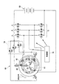
図1は、本発明の実施形態に係るACGスタータ(発電電動機)60が搭載された自動二輪車1の全体構成の一例を示す構成図である。自動二輪車1では、エンジンユニット2が車体前後方向の中央に搭載され、エンジンユニット2の後部上方に乗員が着座するシート3が設けられ、シート3の下方に燃料タンク4が設けられている。<First Embodiment>
[Configuration of motorcycle]
FIG. 1 is a configuration diagram showing an example of the overall configuration of a motorcycle 1 equipped with an ACG starter (generator motor) 60 according to an embodiment of the present invention. In the motorcycle 1, the
前輪Wfは、フロントフォーク5に回転可能に支持される。フロントフォーク5の上部に操舵ハンドル6が設けられている。操舵ハンドル6の右側には、ブレーキレバーBLとスロットルグリップSGが配置されている。また、後輪Wrは、スイングアーム7を介して車体フレームに揺動可能に支持されている。
The front wheel Wf is rotatably supported by the
図2は、図1のA−A断面に対応するエンジンユニット2の展開断面図である。エンジンユニット2は、内燃機関であるレシプロ式のエンジン10と、多段式の変速機11とが一体ブロックとして構成されている。エンジン10と変速機11が遠心クラッチ8とミッションクラッチ12を介して動力伝達可能に構成されている。
FIG. 2 is a developed sectional view of the
エンジン10は、シリンダブロック13のシリンダボア内にピストン14が摺動自在に嵌装されている。ピストン14は、コンロッド15を介してクランク軸16に連結されている。このエンジン10は、図1に示すように、シリンダブロック13がクランク軸16に対して車体前方に延出する略水平姿勢で車両に搭載される。
The
クランク軸16は、シリンダブロック13の基端部に結合されたクランクケース17に軸受18を介して回転可能に支持されている。また、シリンダブロック13の先端部には、ピストン14との間で燃焼室19を形成するシリンダヘッド20が取り付けられている。
The
なお、図2における符号21は、燃焼室19内に臨むようにシリンダヘッド20に設置された点火装置である。また、符号22は、シリンダヘッド20の先端側に設けられ、クランク軸16と連動して図示しない吸排気バルブを開閉駆動する動弁装置であり、ヘッドカバー20Cによって覆われている。また、図2の符号23は、クランク軸16上のコンロッド15との連結部(クランクピン)の軸方向両側に設けられたクランクウェブである。また、符号17aは、クランク軸16のほぼ全域を収容するクランクケース17内のクランク室である。
In addition, the code |
クランク軸16の軸方向の一端部(図2の紙面右側の端部、以下、右端部と呼ぶ)の外周(クランクウェブ23よりも軸方向外側の外周)には、遠心クラッチ8が設けられている。遠心クラッチ8は、クランク軸16の右端部に一体に固定されたクラッチインナ24と、クランク軸16の右端部の外周に回転可能に支持されたクラッチアウタ25と、クラッチインナ24と一体に回転してクラッチインナ24とクラッチアウタ25を遠心力によって接続状態にする遠心ウェイト26と、を備えている。遠心クラッチ8は、クランク軸16の回転速度が所定速度以上に達したときに、クランク軸16の回転動力をクラッチアウタ25に出力する。
A
また、クラッチアウタ25には、ミッションクラッチ12に一体化される入力ギヤ27と噛合する出力ギヤ28が一体回転可能に結合されている。クランクケース17内のクランク軸16の回転中心Oよりも車両後方側位置には、変速機11のメイン軸29とカウンタ軸30がクランク軸16と平行に設けられている。
An
メイン軸29とカウンタ軸30はそれぞれ離間して配置された一対の軸受を介してクランクケース17内に回転可能に支持される。また、メイン軸29はクランク軸16の車両後方側に隣接する位置に配置され、カウンタ軸30はメイン軸29の車両後方側に隣接する位置に配置されている。
The
変速機11のメイン軸29上には、メイン変速ギヤ群M1が配設されている。カウンタ軸30上には、メインギヤ群M1と噛合するカウンタギヤ群M2が配設されている。メイン軸29の軸方向の一端部(図2の紙面右側の端部、以下、右端部と呼ぶ)には、クランク軸16側の出力ギヤ28に噛合される前記の入力ギヤ27とミッションクラッチ12とが設けられている。
A main transmission gear group M <b> 1 is disposed on the
入力ギヤ27は、メイン軸29の外周上に回転可能に支持されている。また、カウンタ軸30の軸方向の他端部(図2の紙面左側の端部)には出力スプロケット33が取り付けられている。出力スプロケット33には動力伝達用のチェーン(図示せず)が掛け回され、当該チェーンを介してカウンタ軸30の回転が駆動輪である後輪Wrに伝達されるようになっている。
The
変速機11では、クランクケース17内に設けられたシフトドラム(不図示)の回動操作によってメインギヤ群M1とカウンタギヤ群M2の駆動伝達ギヤが選択され、それによってニュートラルを含む任意の変速ギヤ段(ギヤポジション)が設定される。
In the
ミッションクラッチ12は、クラッチアウタ35と、クラッチインナ36と、複数の駆動摩擦板37と、複数の従動摩擦板38と、クラッチスプリング(図示せず)と、操作板40と、を備えている。クラッチアウタ35は、入力ギヤ27と一体に結合された状態でメイン軸29上に回転可能に支持された有底円筒状の形状を有する。クラッチインナ36は、メイン軸29にスプライン嵌合された略円盤状の形状を有する。複数の駆動摩擦板37は、クラッチアウタ35に一体回転可能に係止されている。複数の従動摩擦板38は、クラッチインナ36に一体回転可能に係止され駆動摩擦板37と摩擦接触する。クラッチスプリングは、駆動摩擦板37と従動摩擦板38を圧接方向に付勢する。操作盤40は、駆動摩擦板37と従動摩擦板38の間に作用するクラッチスプリングの付勢力を解除操作する。
The
クラッチアウタ35側の駆動摩擦板37とクラッチインナ36側の従動摩擦板38は、軸方向に交互に配置され、クラッチスプリングの付勢力を受けて相互に押し付けられる。これにより、クラッチアウタ35とクラッチインナ36の間の動力伝達が可能となる。また、操作板40によってクラッチスプリングの付勢力が解除操作されることにより、クラッチアウタ35とクラッチインナ36の間の動力伝達が遮断される。
The
本実施形態では、操作板40は、シフトペダル(不図示)の操作に連動して軸方向に進退移動可能に構成される。操作板40は、シフトペダルの操作がなされた際に、変速ギヤが噛み合う前に所定期間だけ駆動摩擦板37と従動摩擦板38の間に作用するクラッチスプリングの付勢力を解除し、それによってクラッチアウタ35とクラッチインナ36の間の動力伝達を遮断する。そして、変速ギヤの噛み合い後に駆動摩擦板37と従動摩擦板38とが噛み合った状態とする。
In the present embodiment, the
また、クランクケース17の後部下側には、キックスタータ41のキックスピンドル42が回動可能に取り付けられている。このキックスピンドル42は、キックペダル43の踏み降ろしがあった場合にのみ、その回転をクランク軸16に伝達するようになっている。
A
一方で、クランク軸16の軸方向の他端部(図2の紙面左側の端部、以下、左端部と呼ぶ)は、クランクケース17の側壁(壁部)に形成された円形状の開口17bを通過してクランクケース17の側壁から外側に突出している。このクランクケース17の開口17bから突出したクランク軸16の左端部側には、交流発電機とエンジン10の始動モータとを兼ねるACGスタータ60が取り付けられている。また、クランク軸16の左端部は、クランクケース17の側壁にボルト締結等によって取り付けられる凹状のエンジンカバー51によって覆われている。
On the other hand, the other end portion in the axial direction of the crankshaft 16 (the left end portion in FIG. 2, hereinafter referred to as the left end portion) is a
エンジンカバー51は、底壁部51aと、側壁部51b(カバー部)と、を備えている。底壁部51aは、左側からクランク軸16の左端部を覆っている。側壁部51bは、底壁部51aの外周縁から立ち上がるように延びて、その先端でクランクケース17の側壁に当接して、クランクケース17に結合している。
The
[ACGスタータの構成および制御]
図3は、第1実施形態に係るACGスタータ60の断面図の一例である。また、図4は、第1実施形態に係る発電電動ユニットのモデル図である。[Configuration and control of ACG starter]
FIG. 3 is an example of a cross-sectional view of the
ACGスタータ60は、制御部70によって駆動されるスイッチング素子群である。ACGスタータ60は、第1のステータ65に接続されたスイッチング素子群72と、第2のステータ68に接続されたスイッチング素子群(スイッチ部)74とによって制御される。各スイッチング素子群は、トランジスタ、IC(Integrated Circuit)、半導体スイッチなど、如何なるスイッチを用いてもよい。制御部70は、例えばCPU(Central Processing Unit)を中心としたマイクロコンピュータである。バッテリ80は、ACGスタータ60を駆動するための電力や、その他の電装品(例えばヘッドランプなど)が動作するための電力を供給すると共に、ACGスタータ60が発電した電力によって充電される。
The
制御部70は、スイッチング素子群72のうち各相のスイッチング素子のゲート端子に対して、ロータ61の回転角に応じたPWM(パルス幅変調)信号を印加し、ロータ61を回転させる。また、制御部70は、スイッチング素子群74に対してロータ61の回転角に応じた信号を印加し、ロータ61の回転をアシストさせる。
The
図5は、第1実施形態に係るACGスタータ60をエンジン10側から見た平面図である。図5において「S」と表されたマグネット62は、径方向内側がS極、外側がN極のマグネットである。また、図5において「N」と表されたマグネット62は、径方向内側がN極、外側がS極のマグネットである。
FIG. 5 is a plan view of the
ACGスタータ60は、クランク軸16と一体回転するロータ(回転子)61と、第1のステータ(固定子)65と、第2のステータ68とを備える。
The
ロータ61は、略円筒状の形状を有しており、底壁部61Aが円盤面をなすと共に、底壁部61Aの反対側が開口してクランク軸16を導入する。ロータ61の側壁部61Bの内周面61Baには、内周面61Baを内側から覆うようにマグネット62が、取り付けまたは形成されている。ロータ61の側壁部61Bの外周面61Bbには、外周面61Bb(壁面)から突出するように磁性体63が、取り付けまたは形成されている。磁性体63は、外周面61Bbから内方または外方に向けて突出して設けられる。
The
第1のステータ65は、例えば、クランクケース17に連結され、ロータ61の径方向に関して内側に収容される。第1のステータ65は、ロータ61方向に突出し、コイルが巻回された複数の外歯状のステータコア66を備える。ステータコア66は、コイル通電することによって発生する磁束をマグネット62に作用させることにより、ロータ61にトルクを発生させる。また、第1のステータ65は、自動二輪車1の走行に伴うロータ61の回転により生じる電磁誘導の作用により発電する。第1のステータ65が発電した電力は、バッテリ80(後述)に蓄えられる。
For example, the
第2のステータ68は、例えば、エンジンカバー51の側壁部51bに連結され、ロータ61の径方向に関して外側に設置される。第2のステータ68は、ロータ61方向に突出し、コイルが巻回された複数の内歯状のステータコア69を備える。第2のステータ68は、コイルに通電することによって発生する磁束を磁性体63に作用させることにより、ロータ61にトルクを発生させる。
For example, the
図5に示すように、第1のステータ65は、ステータコア66を例えば18極備え、U極、V極、W極が1つずつ順に配置された構造となっている。第1のステータ65は、周知の三相制御によってロータ61に配置されたマグネット62に磁束を作用させ、ロータ61にトルクを発生させる。
As shown in FIG. 5, the
また、第2のステータ68は、ステータコア69を例えば18極備え、ステータコア69は、U+極、V+極、W+極、U―極、V―極、W―極の順に3組、周方向に並べられて配置されている。第2のステータ68は、U+極からU―極、V+極からV―極、W+極からW―極に向けて磁束を発生させ、磁性体63に作用させることで、ロータ61にトルクを発生させる。The
図6(A)〜(C)は、第1のステータ65および第2のステータ68が三相制御されることによってロータ61が回転駆動される様子を模式的に示す図である。図6の例では、第2のステータ68の各相が第1のステータの各相よりもロータ61の回転方向に位相を20[deg]進めて配置されている。図6(A)に示すように、ロータ61の回転角が0[deg](基準位置)のときにはU相のステータコア66、69に通電される。図6(B)に示すように、ロータ61の回転角が20[deg]のときにはV相のステータコア66、69に通電される。図6(C)に示すように、ロータ61の回転角が40[deg]のときにはW相のステータコア66、69に通電される。第1のステータ65は、ロータ61を回転方向に押すようにトルクをかけ、第2のステータ68はロータ61を回転方向に引くようにトルクをかける。
FIGS. 6A to 6C are diagrams schematically showing how the
<第2実施形態>
図7は、第2実施形態に係る発電電動ユニットのモデル図である。第2実施形態に係る発電電動ユニットでは、マグネット62は、ロータ61の周方向にある程度の間隔をもって配置される。マグネット62は、第1のステータ65と第2のステータ68の各相の+極と―極が対向するように配置され、マグネット62の間を第1のステータ65と第2のステータ68が発生させる磁束が通過する構造を有する。Second Embodiment
FIG. 7 is a model diagram of the generator-motor unit according to the second embodiment. In the generator-motor unit according to the second embodiment, the
これによって、より効率的にトルクを発生させることができる。この場合、磁束とマグネット62の反発力を利用して、ACGスタータ60を電磁ブレーキ(回生ブレーキ)として利用してもよい。図8Aは、マグネット62間を通過する磁束によりトルクを発生させる様子を示す図である。図8Bは、マグネット62間を通過する磁束によりロータ61を停止させるトルクを発生させる様子を示す図である。制御部70は、例えば高速走行時においてスロットルグリップ(減速操作子)SGが戻されて減速するときや、ブレーキレバー(減速操作子)BLが所定量以上操作されたときに、ロータ61の回転方向と逆向きのトルク(負のトルク)を発生させ、電磁的にブレーキをかけると共に、回生発電を行わせる。すなわち、制御部70は、上記のような減速の操作がされた場合に、第2のステータ68(第2の固定子)のコイルへの通電を行うことによって、ロータ61(回転子)の回転方向に対して負のトルクを発生させることができる。
Thereby, torque can be generated more efficiently. In this case, the
制御部70は、イグニッションスイッチ(不図示)から入力される信号に従って、エンジン10を始動させるためのトルクをACGスタータ60に出力させる。この場合、制御部70は、スイッチング素子群72とスイッチング素子群74の双方を制御することにより、ACGスタータ60に大きいトルクを出力させる。また、制御部70は、自動二輪車1の発進直後の低回転時における加速時(スロットルグリップ(加速操作子)SGが所定量以上操作されたとき)など、クランク軸16に強いトルク(発進の際のアシストトルク)が必要とされる場合にも、エンジン10の始動時と同じ制御を行い、ロータ61の回転方向と同じ向きのトルク(正のトルク)を発生させてよい。すなわち、制御部70は、上記のように加速操作子が操作された場合に、第2のステータ68(第2の固定子)のコイルへの通電を行うことによって、ロータ61(回転子)の回転方向に対して正のトルクを発生させることができる。
一方、制御部70は、ACGスタータ60に発電させてバッテリ80を充電する際には、スイッチング素子群72のみを制御し、スイッチング素子群74を全てオフ状態に維持する。これによって、ACGスタータ60は、エンジン10の始動時に出力するトルクとの関係で、相対的に小さい発電量で発電を行うことができる。この結果、ACGスタータ60(発電電動機)の最大トルクと発電量の関係を良好にすることができる。
On the other hand, when the
ここで、エンジン10の始動には、圧縮上死点を乗り越えるために比較的大きいトルクが要求されるのが一般的である。このため、特に排気量が大きいエンジン10の始動のために十分なトルクを発生させることが可能な大規模なマグネットモータをACGスタータとして備えた場合、発電量に余剰が生じると共に、フリクションが増える傾向にある。
Here, in order to start over the
これに対し本実施形態のACGスタータ60および制御部70(発電電動ユニット)によれば、エンジン10の始動時には、スイッチング素子群72とスイッチング素子群74の双方を制御してACGスタータ60に大きいトルクを出力させる。また、ACGスタータ60の発電時にはスイッチング素子群72のみを制御し、スイッチング素子群74を全てオフ状態に維持する。そのため、最大トルクを大きくすると共に適度な発電量で発電を行うことができる。この結果、フリクションの増加を抑制しつつ、トルク出力性能を向上させることができる。
On the other hand, according to the
[まとめ]
以上説明した本実施形態の発電電動機、発電電動ユニット、および動力出力機関(エンジン10、ACGスタータ60、制御部70)によれば、フリクションの増加を抑制しつつ、トルク出力性能を向上させることができる。[Summary]
According to the generator motor, the generator motor unit, and the power output engine (the
なお、上記説明したACGスタータ60の各ステータの極数などは、あくまで一例であり、ACGスタータ60が使用される場面に応じて任意に変更されてよい。
The number of poles of each stator of the
<第3実施形態>
以下、本発明の第2実施形態に係るACGスタータ90について説明する。第2実施形態に係る自動二輪車は、ACGスタータ60に代えてACGスタータ90を搭載し、それ以外の部分については第1実施形態と同様である。そのため、ここではACGスタータ90の構造についてのみ説明する。<Third Embodiment>
Hereinafter, the
図9は、第2実施形態に係るACGスタータ90の断面の一例である。ACGスタータ90は、クランク軸16と一体回転するロータ(回転子)91と、第1のステータ(固定子)96と、第2のステータ99とを備える。また、図10は、第2実施形態に係るロータ91の外観形状を示す斜視図である。
FIG. 9 is an example of a cross section of the
ロータ91は、略円筒状の形状を有する第1円筒部材92と、第2円筒部材94とを備える。第2円筒部材94は、第1円筒部材92の底壁部(円盤面)92Aからロータ91の回転軸方向(エンジン10と反対の方向)に延出している。
The
第1円筒部材92は、底壁部92Aの反対側が開口してクランク軸16を導入する。第1円筒部材92の側壁部92Bの内周面92Baには、内周面92Baを覆うようにマグネット93が取り付けまたは形成されている。また、第2円筒部材94の外周面94Aには、外周面94A(壁面)から外側に突出するように磁性体95が取り付けまたは形成されている。磁性体95は、外周面94Aから内方または外方に向けて突出して設けられる。
The first
第1のステータ96は、例えば、クランクケース17に連結され、第1円筒部在92の径方向に関して内側に収容される。第1のステータ96は、第1円筒部在92が設けられている方向に向かって突出し、コイルが巻回された複数の外歯状のステータコア97を備える。ステータコア97は、コイル通電することによって発生する磁束をマグネット93に作用させることにより、ロータ91にトルクを発生させる。また、第1のステータ96は、自動二輪車1の走行に伴うロータ91の回転により生じる電磁誘導の作用により発電する。第1のステータ96が発電した電力は、バッテリ80に蓄えられる。
For example, the
第2のステータ99は、例えば、エンジンカバー51の側壁部51bに連結され、第2円筒部材94の径方向に関して外側に設置される。第2のステータ99は、第2円筒部材94が設けられている方向に向かって突出し、コイルが巻回された複数の内歯状のステータコア100を備える。第2のステータ99は、コイルに通電することによって発生する磁束を磁性体95に作用させることにより、ロータ91にトルクを発生させる。
For example, the
第1実施形態の図4に示すように、第1のステータ96は、ステータコア97を例えば18極備え、U極、V極、W極が1つずつ順に配置された構造となっている。第1のステータ96は、周知の三相制御によって第1円筒部材92に配置されたマグネット93に磁束を作用させ、ロータ91にトルクを発生させる。
As shown in FIG. 4 of the first embodiment, the
また、第2のステータ99は、ステータコア100を例えば18極備える。ステータコア100は、U+極、V+極、W+極、U―極、V―極、W―極の順に3組、周方向に並べられて配置されている。第2のステータ99は、U+極からU―極、V+極からV―極、W+極からW―極に向けて磁束を発生させ、磁性体95に磁束を作用させることで、ロータ91にトルクを発生させる。Further, the
第2実施形態における制御部70は、第1実施形態と同様、イグニッションスイッチ(不図示)から入力される信号に従って、エンジン10を始動させるためのトルクをACGスタータ60に出力させる。この場合、制御部70は、スイッチング素子群72とスイッチング素子群74の双方を制御することにより、ACGスタータ60に大きいトルクを出力させる。
As in the first embodiment, the
また、制御部70は、自動二輪車1の発進直後の低回転時における加速時(スロットルグリップSGが所定量以上操作されたとき)など、クランク軸16に強いトルク(発進の際のアシストトルク)が必要とされる場合にも、エンジン10の始動時と同じ制御を行い、ロータ61の回転方向と同じ向きのトルク(正のトルク)を発生させてよい。
Further, the
一方、制御部70は、ACGスタータ60に発電させてバッテリ80を充電する際には、スイッチング素子群72のみを制御し、スイッチング素子群74を全てオフ状態に維持する。これによって、ACGスタータ60は、エンジン10の始動時に出力するトルクとの関係で、相対的に小さい発電量で発電を行うことができる。この結果、ACGスタータ60(発電電動機)の最大トルクと発電量の関係を良好にすることができる。
On the other hand, when the
以上説明した本実施形態の発電電動機、発電電動ユニット、および動力出力機関(エンジン10、ACGスタータ60、制御部70)によれば、フリクションの増加を抑制しつつ、トルク出力性能を向上させることができる。
According to the generator motor, the generator motor unit, and the power output engine (the
<第4実施形態>
また、上記実施形態では、ACGスタータ60または90の第1ステータがロータの円筒部材の内側から磁束を作用させ、第2ステータが外側から磁束を作用させるものとしたが、この関係が逆であってもよい。すなわち、ロータは、円筒部材の外周面にマグネットを取り付けまたは形成し、内周面に磁性体を取り付けまたは形成し、第1ステータは円筒部材の外側からマグネットに磁束を作用させ、第2ステータは円筒部材の内側から磁性体に磁束を作用させる。いわゆるインナーロータ型のマグネットモータのロータの内側に磁性体を取り付けまたは形成し、ロータの内側に第2ステータを配置する。<Fourth embodiment>
In the above embodiment, the first stator of the
図11は、第4実施形態に係るACGスタータ120の第1のステータ125および第2のステータ128が三相制御されることによってロータ121が回転駆動される様子を模式的に示す図である。第4実施形態に係るACGスタータ120は、内側に磁性体123が、外側にマグネット122が取り付けまたは形成されたロータ(インナーロータ)121と、ロータ121の外側からマグネット122に磁束を作用させてトルクを発生させる第1ステータ125と、ロータ121の内側から磁性体123に磁束を作用させてトルクを発生させる第2ステータ128とを備える。
FIG. 11 is a diagram schematically illustrating how the
<変形等>
以上、本発明を実施するための形態について実施形態を用いて説明したが、本発明はこうした実施形態に何等限定されるものではなく、本発明の要旨を逸脱しない範囲内において種々の変形及び置換を加えることができる。<Deformation, etc.>
As mentioned above, although the form for implementing this invention was demonstrated using embodiment, this invention is not limited to such embodiment at all, In the range which does not deviate from the summary of this invention, various deformation | transformation and substitution Can be added.
例えば、ACGスタータ60または90が搭載される車両は、実施形態で説明した態様の自動二輪車に限らず、無段変速機を備えるスクーター、マニュアル式の自動二輪車、エンジン付自転車、軽自動車、普通自動車、大型車両などであってもよい。
For example, the vehicle on which the
また、上記実施形態では、ACGスタータ60または90は三相で駆動されるものとしたが、単相またはより多い相で駆動されてもよい。
In the above embodiment, the
また、制御部70は、自動二輪車1の発進直後の低回転時における加速時に限らず、中〜高回転時における加速時にも、エンジン10の始動時と同じ制御を行ってよい。また、制御部70は、自動二輪車1の高速走行時における減速時に限らず、低〜中回転時における減速時にも、電磁ブレーキとしてACGスタータを動作させてよい。
The
また、運転者によって操作可能なスイッチを備え、このスイッチが操作され且つスロットルグリップSGが所定量以上操作されたときに、ACGスタータにロータの回転方向と同じ向きのトルク(正のトルク)を発生させてよい。 In addition, a switch that can be operated by the driver is provided, and when this switch is operated and the throttle grip SG is operated more than a predetermined amount, the ACG starter generates torque in the same direction as the rotation direction of the rotor (positive torque). You may let me.
なお、上述の第1実施形態〜第4実施形態の技術は、それぞれ適宜に組み合わせて用いることができる。また、一部の構成要素が省略されてもよい。 Note that the techniques of the first to fourth embodiments described above can be used in appropriate combinations. Some of the components may be omitted.
10 エンジン(内燃機関)
16 クランク軸(内燃機関の回転出力軸)
17 クランクケース
51 エンジンカバー(カバー部)
60、90 ACGスタータ(発電電動機)
61、91 ロータ(回転子)
62、93 マグネット(磁石)
63、95 磁性体
65、96 第1のステータ(第1の固定子)
66、69、97、100 ステータコア
68、99 第2のステータ(第2の固定子)
70 制御部
72、74 スイッチング素子群(スイッチ部)
80 バッテリ
92 第1円筒部材
94 第2円筒部材10 Engine (Internal combustion engine)
16 Crankshaft (rotary output shaft of internal combustion engine)
17
60, 90 ACG starter (generator motor)
61, 91 Rotor (rotor)
62, 93 Magnet (magnet)
63, 95
66, 69, 97, 100
70
80
Claims (13)
前記磁石に磁束を作用させることにより前記回転子にトルクを発生させる第1の固定子と、
前記磁性体に磁束を作用させることにより前記回転子にトルクを発生させる第2の固定子であって、前記磁束を発生させるためのコイルへの通電を遮断することが可能なスイッチ部を備える第2の固定子と、
を備える発電電動機と、
前記回転子の回転方向にトルクを発生させるときには、前記第1の固定子および前記第2の固定子に磁束を発生させるように前記第1の固定子および前記第2の固定子のコイルへの通電を行い、前記回転子の回転により生じる電磁誘導の作用により発電するときには、前記第1の固定子のコイルへの通電を行うと共に前記スイッチ部をオフ状態にして前記第2の固定子のコイルへの通電を遮断する制御部と、
を備える発電電動ユニット。 A rotor including a magnet and a magnetic body protruding from the wall surface;
A first stator that generates torque on the rotor by applying magnetic flux to the magnet;
A second stator that generates torque on the rotor by applying magnetic flux to the magnetic body, and includes a switch portion that can cut off the energization to the coil for generating the magnetic flux. Two stators,
A generator motor comprising:
When generating torque in the rotation direction of the rotor, the first stator and the second stator are applied to coils of the first stator and the second stator so that magnetic flux is generated in the first stator and the second stator. performs energization, when power generation by the action of electromagnetic induction caused by the rotation of the rotor, prior Symbol the second stator and the switch unit in an off state performs energization of the first coil of the stator A control unit that cuts off power to the coil;
A generator motor unit comprising:
前記磁石は、前記回転子における略円筒形状の部材の内周面に配置され、
前記第1の固定子は、前記略円筒形状の部材の径内方向から前記磁石に磁束を作用させ、
前記磁性体は、前記回転子における略円筒形状の部材の外周面に配置され、
前記第2の固定子は、前記略円筒形状の部材の径外方向から前記磁性体に磁束を作用させる、
発電電動ユニット。The generator-motor unit according to claim 1,
The magnet is disposed on an inner peripheral surface of a substantially cylindrical member in the rotor,
The first stator causes a magnetic flux to act on the magnet from the radially inward direction of the substantially cylindrical member,
The magnetic body is disposed on an outer peripheral surface of a substantially cylindrical member in the rotor,
The second stator causes a magnetic flux to act on the magnetic body from a radially outward direction of the substantially cylindrical member.
Electric generator unit.
前記磁石と前記磁性体は、前記回転子における同じ略円筒形状の部材の内周面と外周面に、それぞれ配置される、
発電電動ユニット。The generator-motor unit according to claim 2,
The magnet and the magnetic body are respectively disposed on the inner peripheral surface and the outer peripheral surface of the same substantially cylindrical member in the rotor,
Electric generator unit.
前記磁石は、前記略円筒形状の周方向に関して間隔をもって配置され、前記磁石の間を前記第1の固定子および前記第2の固定子が発生させる磁束が通過する、
発電電動ユニット。The generator-motor unit according to claim 3,
The magnets are arranged at intervals with respect to the circumferential direction of the substantially cylindrical shape, and the magnetic flux generated by the first stator and the second stator passes between the magnets.
Electric generator unit.
前記回転子は、軸が共通する第1円筒部材と第2円筒部材とを備え、
前記磁石は、前記第1円筒部材と前記第2円筒部材のうち一方の内周面に配置され、
前記磁性体は、前記第1円筒部材と前記第2円筒部材のうち他方の外周面に配置される、
発電電動ユニット。The generator-motor unit according to claim 1,
The rotor includes a first cylindrical member and a second cylindrical member having a common axis,
The magnet is disposed on one inner peripheral surface of the first cylindrical member and the second cylindrical member,
The magnetic body is disposed on the other outer peripheral surface of the first cylindrical member and the second cylindrical member.
Electric generator unit.
前記磁石は、前記回転子における略円筒形状の部材の外周面に配置され、
前記第1の固定子は、前記略円筒形状の部材の径外方向から前記磁石に磁束を作用させ、
前記磁性体は、前記回転子における略円筒形状の部材の内周面に配置され、
前記第2の固定子は、前記略円筒形状の部材の径内方向から前記磁性体に磁束を作用させる、
発電電動ユニット。The generator-motor unit according to claim 1,
The magnet is disposed on an outer peripheral surface of a substantially cylindrical member in the rotor,
The first stator causes a magnetic flux to act on the magnet from a radially outward direction of the substantially cylindrical member,
The magnetic body is disposed on an inner peripheral surface of a substantially cylindrical member in the rotor,
The second stator causes a magnetic flux to act on the magnetic body from a radially inward direction of the substantially cylindrical member.
Electric generator unit.
回転駆動力を出力する内燃機関と、を備え、
前記内燃機関の回転出力軸に前記回転子が連結された動力出力機関。The generator motor unit according to claim 1;
An internal combustion engine that outputs a rotational driving force,
A power output engine in which the rotor is connected to a rotation output shaft of the internal combustion engine.
前記制御部は、前記内燃機関を始動するときには、前記第1の固定子および前記第2の固定子に磁束を発生させるように前記第1の固定子および前記第2の固定子のコイルへの通電を行い、前記内燃機関の出力する動力を用いて発電するときには、前記第1の固定子に磁束を発生させるように前記第1の固定子のコイルへの通電を行うと共に前記スイッチ部をオフ状態にして前記第2の固定子のコイルへの通電を遮断する、
動力出力機関。A power output engine according to claim 7,
When the internal combustion engine is started, the control unit applies coils to the first stator and the second stator so as to generate magnetic flux in the first stator and the second stator. When energizing and generating power using the power output from the internal combustion engine, the coil of the first stator is energized and the switch unit is turned off so as to generate a magnetic flux in the first stator. Cutting off the energization of the coil of the second stator in a state;
Power output engine.
前記第2の固定子は、前記内燃機関のカバー部に固定される、
動力出力機関。A power output engine according to claim 7,
The second stator is fixed to a cover portion of the internal combustion engine;
Power output engine.
前記第2の固定子は、前記内燃機関のカバー部に固定される、
動力出力機関。The power output engine according to claim 8,
The second stator is fixed to a cover portion of the internal combustion engine;
Power output engine.
加速操作子とを有する車両であって、
前記制御部は、前記加速操作子が操作された場合に、前記第2の固定子のコイルへの通電を行うことによって、前記回転子の回転方向に対して正のトルクを発生させる、
車両。A power output engine according to claim 7;
A vehicle having an acceleration operator,
The control unit generates a positive torque with respect to the rotation direction of the rotor by energizing the coil of the second stator when the acceleration operator is operated.
vehicle.
減速操作子とを有する車両であって、
前記制御部は、減速の操作がされた場合に、前記第2の固定子のコイルへの通電を行うことによって、前記回転子の回転方向に対して負のトルクを発生させる、
車両。A power output engine according to claim 7;
A vehicle having a deceleration operator,
The control unit generates a negative torque with respect to the rotation direction of the rotor by energizing the coil of the second stator when a deceleration operation is performed.
vehicle.
減速操作子とを有する車両であって、
前記制御部は、減速の操作がされた場合に、前記第2の固定子のコイルへの通電を行うことによって、前記回転子の回転方向に対して負のトルクを発生させる、
車両。A power output engine according to claim 8,
A vehicle having a deceleration operator,
The control unit generates a negative torque with respect to the rotation direction of the rotor by energizing the coil of the second stator when a deceleration operation is performed.
vehicle.
Applications Claiming Priority (3)
| Application Number | Priority Date | Filing Date | Title |
|---|---|---|---|
| JP2013046997 | 2013-03-08 | ||
| JP2013046997 | 2013-03-08 | ||
| PCT/JP2013/083079 WO2014136343A1 (en) | 2013-03-08 | 2013-12-10 | Generator motor unit, power output engine, and vehicle |
Publications (2)
| Publication Number | Publication Date |
|---|---|
| JP5953423B2 true JP5953423B2 (en) | 2016-07-20 |
| JPWO2014136343A1 JPWO2014136343A1 (en) | 2017-02-09 |
Family
ID=51490886
Family Applications (1)
| Application Number | Title | Priority Date | Filing Date |
|---|---|---|---|
| JP2015504134A Active JP5953423B2 (en) | 2013-03-08 | 2013-12-10 | Generator / motor unit, power output engine, and vehicle |
Country Status (8)
| Country | Link |
|---|---|
| US (1) | US9637008B2 (en) |
| EP (1) | EP2966761B1 (en) |
| JP (1) | JP5953423B2 (en) |
| CN (1) | CN105122612B (en) |
| BR (1) | BR112015021569B1 (en) |
| MY (1) | MY181431A (en) |
| PH (1) | PH12015501935A1 (en) |
| WO (1) | WO2014136343A1 (en) |
Families Citing this family (10)
| Publication number | Priority date | Publication date | Assignee | Title |
|---|---|---|---|---|
| EP2966761B1 (en) * | 2013-03-08 | 2020-06-03 | Honda Motor Co., Ltd. | Generator motor unit, power output engine, and vehicle |
| KR20160004876A (en) * | 2014-07-05 | 2016-01-13 | 한승주 | Variable Power Transmission Device |
| CN107078617B (en) * | 2014-10-17 | 2019-03-19 | 株式会社Ihi | Bimorph transducer type rotator |
| KR101516389B1 (en) * | 2014-10-20 | 2015-05-26 | ㈜대신산업개발 | Motor generator driving and electric charging at the same time |
| JP6834240B2 (en) * | 2016-08-15 | 2021-02-24 | スズキ株式会社 | Motorcycle |
| JP6546967B2 (en) | 2017-07-10 | 2019-07-17 | 本田技研工業株式会社 | Power plant |
| JP2020152120A (en) * | 2017-07-18 | 2020-09-24 | ヤマハ発動機株式会社 | Vehicle |
| WO2020044481A1 (en) * | 2018-08-30 | 2020-03-05 | ヤマハ発動機株式会社 | Engine-driven saddled vehicle |
| CN110065387A (en) * | 2019-04-26 | 2019-07-30 | 湖北启源科技有限公司 | A kind of electric piston drive type electric vehicle and its working method |
| IT201900022482A1 (en) * | 2019-11-29 | 2021-05-29 | Piaggio & C Spa | RIDING SADDLE VEHICLE WITH HYBRID PROPULSION |
Citations (5)
| Publication number | Priority date | Publication date | Assignee | Title |
|---|---|---|---|---|
| JPH0775212A (en) * | 1993-08-31 | 1995-03-17 | Hitachi Ltd | Rotating machine, with rechargeable machine drive unit electric and electric vehicle |
| JP2008259303A (en) * | 2007-04-04 | 2008-10-23 | Honda Motor Co Ltd | Controller of electric motor |
| JP2010098853A (en) * | 2008-10-16 | 2010-04-30 | Toyota Auto Body Co Ltd | Double stator motor |
| JP2010208485A (en) * | 2009-03-10 | 2010-09-24 | Mazda Motor Corp | Control device for hybrid car |
| JP2012165577A (en) * | 2011-02-08 | 2012-08-30 | Seiko Epson Corp | Relative driving system, mobile object, and robot |
Family Cites Families (24)
| Publication number | Priority date | Publication date | Assignee | Title |
|---|---|---|---|---|
| EP0577980B1 (en) * | 1992-06-10 | 1997-09-10 | Fuji Electric Co., Ltd. | Ac variable speed driving apparatus and electric vehicle using the same |
| DE4318949C2 (en) | 1993-02-19 | 1999-03-18 | Mannesmann Ag | Electrical machine with at least one clutch |
| US5530309A (en) * | 1993-05-04 | 1996-06-25 | Board Of Regents, The University Of Texas System | Homopolar machine |
| DE69635942T8 (en) * | 1995-05-19 | 2007-04-26 | Toyota Jidosha Kabushiki Kaisha, Toyota | Drive arrangement and power control for a hybrid vehicle |
| JP3211702B2 (en) * | 1997-02-25 | 2001-09-25 | 株式会社デンソー | Hybrid vehicle control device |
| DE19704271A1 (en) * | 1997-02-05 | 1998-08-06 | Egon Schmid | Electric machine with stator and rotor |
| JP2000350309A (en) * | 1999-06-04 | 2000-12-15 | Denso Corp | Power converting system and driving system in vehicle |
| DE19960168A1 (en) * | 1999-12-14 | 2001-06-21 | Volkswagen Ag | Generator-motor combination |
| DE10110903A1 (en) * | 2000-04-07 | 2001-10-11 | Volkswagen Ag | Electrical machine e.g. starter/generator unit for motor vehicle, has second stator located rigidly in housing that interacts with rotor by induction |
| US20030052564A1 (en) * | 2001-07-09 | 2003-03-20 | Doris Wilsdorf | Bipolar machines-a new class of homopolar motor/generator |
| AU2002335196A1 (en) | 2002-10-04 | 2004-04-23 | Mitsuba Corporation | Starting power generation system and starting power generator |
| US6965183B2 (en) * | 2003-05-27 | 2005-11-15 | Pratt & Whitney Canada Corp. | Architecture for electric machine |
| CN2640115Y (en) * | 2003-06-12 | 2004-09-08 | 哈尔滨工业大学 | Direct drive mixed reluctance electric machine |
| JP4742992B2 (en) * | 2006-05-30 | 2011-08-10 | トヨタ自動車株式会社 | Power output apparatus and vehicle equipped with the same |
| JP4985956B2 (en) * | 2007-04-13 | 2012-07-25 | 本田技研工業株式会社 | Electric motor control device |
| JP4466882B2 (en) | 2007-08-03 | 2010-05-26 | 本田技研工業株式会社 | Electric motor control device |
| US8125168B2 (en) * | 2007-11-19 | 2012-02-28 | Honeywell International Inc. | Motor having controllable torque |
| JP2009222036A (en) * | 2008-03-19 | 2009-10-01 | Hitachi Ltd | Valve timing control device of internal combustion engine |
| JP5241021B2 (en) | 2009-03-24 | 2013-07-17 | 本田技研工業株式会社 | Engine start control device |
| JP5208154B2 (en) * | 2010-04-20 | 2013-06-12 | 日立オートモティブシステムズ株式会社 | Valve timing control device for internal combustion engine |
| CN102223033A (en) * | 2011-05-27 | 2011-10-19 | 山东理工大学 | Generator for range extender of electric vehicle |
| JP5720958B2 (en) * | 2012-09-06 | 2015-05-20 | 株式会社デンソー | Rotating electric machine drive system |
| TWI628908B (en) * | 2012-12-10 | 2018-07-01 | 澳大利亞商艾克西弗洛克斯控股私營有限公司 | Electric motor/generator with integrated differential |
| EP2966761B1 (en) * | 2013-03-08 | 2020-06-03 | Honda Motor Co., Ltd. | Generator motor unit, power output engine, and vehicle |
-
2013
- 2013-12-10 EP EP13877372.6A patent/EP2966761B1/en active Active
- 2013-12-10 MY MYPI2015702969A patent/MY181431A/en unknown
- 2013-12-10 WO PCT/JP2013/083079 patent/WO2014136343A1/en active Application Filing
- 2013-12-10 BR BR112015021569-6A patent/BR112015021569B1/en not_active IP Right Cessation
- 2013-12-10 US US14/772,449 patent/US9637008B2/en not_active Expired - Fee Related
- 2013-12-10 CN CN201380074249.0A patent/CN105122612B/en active Active
- 2013-12-10 JP JP2015504134A patent/JP5953423B2/en active Active
-
2015
- 2015-09-02 PH PH12015501935A patent/PH12015501935A1/en unknown
Patent Citations (5)
| Publication number | Priority date | Publication date | Assignee | Title |
|---|---|---|---|---|
| JPH0775212A (en) * | 1993-08-31 | 1995-03-17 | Hitachi Ltd | Rotating machine, with rechargeable machine drive unit electric and electric vehicle |
| JP2008259303A (en) * | 2007-04-04 | 2008-10-23 | Honda Motor Co Ltd | Controller of electric motor |
| JP2010098853A (en) * | 2008-10-16 | 2010-04-30 | Toyota Auto Body Co Ltd | Double stator motor |
| JP2010208485A (en) * | 2009-03-10 | 2010-09-24 | Mazda Motor Corp | Control device for hybrid car |
| JP2012165577A (en) * | 2011-02-08 | 2012-08-30 | Seiko Epson Corp | Relative driving system, mobile object, and robot |
Also Published As
| Publication number | Publication date |
|---|---|
| PH12015501935B1 (en) | 2016-01-11 |
| PH12015501935A1 (en) | 2016-01-11 |
| US20160009185A1 (en) | 2016-01-14 |
| CN105122612A (en) | 2015-12-02 |
| US9637008B2 (en) | 2017-05-02 |
| EP2966761B1 (en) | 2020-06-03 |
| CN105122612B (en) | 2017-11-21 |
| BR112015021569B1 (en) | 2021-08-24 |
| JPWO2014136343A1 (en) | 2017-02-09 |
| WO2014136343A1 (en) | 2014-09-12 |
| BR112015021569A2 (en) | 2017-07-18 |
| EP2966761A4 (en) | 2017-01-11 |
| EP2966761A1 (en) | 2016-01-13 |
| MY181431A (en) | 2020-12-21 |
Similar Documents
| Publication | Publication Date | Title |
|---|---|---|
| JP5953423B2 (en) | Generator / motor unit, power output engine, and vehicle | |
| JP6038285B2 (en) | Generator motor unit and generator motor control method | |
| JP6802378B2 (en) | Vehicle | |
| JP4573298B2 (en) | Rotational fluctuation control device for internal combustion engine | |
| JP5692027B2 (en) | Engine accessory system for motorcycles | |
| WO2020044481A1 (en) | Engine-driven saddled vehicle | |
| JP5515334B2 (en) | Control device for hybrid vehicle | |
| TWI788379B (en) | vehicle | |
| JP2019054559A (en) | Vehicle | |
| JP2011255706A (en) | Drive device for hybrid vehicle | |
| JPH09322311A (en) | Power output device | |
| TWI682864B (en) | vehicle | |
| CN103963779B (en) | Control method, control system and the vehicle of motor | |
| JP2014177868A (en) | Vehicle electric generator | |
| JP6298233B2 (en) | Motor control method and motor control system | |
| CN110462184B (en) | Vehicle engine control device | |
| JP2010195126A (en) | Controller of driving device for hybrid vehicle | |
| WO2014083995A1 (en) | Travel control device | |
| JPH09154300A (en) | Power transmission apparatus and control method thereof | |
| JP5155576B2 (en) | Electric vehicle drive | |
| JP2009006890A (en) | Hybrid vehicle | |
| JP2004017942A (en) | Hybrid automobile |
Legal Events
| Date | Code | Title | Description |
|---|---|---|---|
| TRDD | Decision of grant or rejection written | ||
| A01 | Written decision to grant a patent or to grant a registration (utility model) |
Free format text: JAPANESE INTERMEDIATE CODE: A01 Effective date: 20160517 |
|
| A61 | First payment of annual fees (during grant procedure) |
Free format text: JAPANESE INTERMEDIATE CODE: A61 Effective date: 20160613 |
|
| R150 | Certificate of patent or registration of utility model |
Ref document number: 5953423 Country of ref document: JP Free format text: JAPANESE INTERMEDIATE CODE: R150 |