JP5951583B2 - Image reading apparatus and image forming apparatus provided with image reading apparatus - Google Patents
Image reading apparatus and image forming apparatus provided with image reading apparatus Download PDFInfo
- Publication number
- JP5951583B2 JP5951583B2 JP2013227763A JP2013227763A JP5951583B2 JP 5951583 B2 JP5951583 B2 JP 5951583B2 JP 2013227763 A JP2013227763 A JP 2013227763A JP 2013227763 A JP2013227763 A JP 2013227763A JP 5951583 B2 JP5951583 B2 JP 5951583B2
- Authority
- JP
- Japan
- Prior art keywords
- image reading
- document
- holding means
- document pressing
- reading apparatus
- Prior art date
- Legal status (The legal status is an assumption and is not a legal conclusion. Google has not performed a legal analysis and makes no representation as to the accuracy of the status listed.)
- Expired - Fee Related
Links
- 230000000903 blocking effect Effects 0.000 claims description 3
- 239000011521 glass Substances 0.000 description 24
- 238000010586 diagram Methods 0.000 description 4
- 238000000034 method Methods 0.000 description 2
- 239000000853 adhesive Substances 0.000 description 1
- 230000001070 adhesive effect Effects 0.000 description 1
- 230000001771 impaired effect Effects 0.000 description 1
- 230000001678 irradiating effect Effects 0.000 description 1
- 229920003002 synthetic resin Polymers 0.000 description 1
- 239000000057 synthetic resin Substances 0.000 description 1
Images


Classifications
-
- G—PHYSICS
- G03—PHOTOGRAPHY; CINEMATOGRAPHY; ANALOGOUS TECHNIQUES USING WAVES OTHER THAN OPTICAL WAVES; ELECTROGRAPHY; HOLOGRAPHY
- G03B—APPARATUS OR ARRANGEMENTS FOR TAKING PHOTOGRAPHS OR FOR PROJECTING OR VIEWING THEM; APPARATUS OR ARRANGEMENTS EMPLOYING ANALOGOUS TECHNIQUES USING WAVES OTHER THAN OPTICAL WAVES; ACCESSORIES THEREFOR
- G03B27/00—Photographic printing apparatus
- G03B27/32—Projection printing apparatus, e.g. enlarger, copying camera
- G03B27/52—Details
- G03B27/62—Holders for the original
-
- G—PHYSICS
- G03—PHOTOGRAPHY; CINEMATOGRAPHY; ANALOGOUS TECHNIQUES USING WAVES OTHER THAN OPTICAL WAVES; ELECTROGRAPHY; HOLOGRAPHY
- G03G—ELECTROGRAPHY; ELECTROPHOTOGRAPHY; MAGNETOGRAPHY
- G03G15/00—Apparatus for electrographic processes using a charge pattern
-
- H—ELECTRICITY
- H04—ELECTRIC COMMUNICATION TECHNIQUE
- H04N—PICTORIAL COMMUNICATION, e.g. TELEVISION
- H04N1/00—Scanning, transmission or reproduction of documents or the like, e.g. facsimile transmission; Details thereof
- H04N1/00519—Constructional details not otherwise provided for, e.g. housings, covers
- H04N1/00551—Top covers or the like
- H04N1/00554—Latches or hinges therefor
-
- H—ELECTRICITY
- H04—ELECTRIC COMMUNICATION TECHNIQUE
- H04N—PICTORIAL COMMUNICATION, e.g. TELEVISION
- H04N1/00—Scanning, transmission or reproduction of documents or the like, e.g. facsimile transmission; Details thereof
- H04N1/00519—Constructional details not otherwise provided for, e.g. housings, covers
- H04N1/00557—Connection or assembly of components or elements
-
- H—ELECTRICITY
- H04—ELECTRIC COMMUNICATION TECHNIQUE
- H04N—PICTORIAL COMMUNICATION, e.g. TELEVISION
- H04N1/00—Scanning, transmission or reproduction of documents or the like, e.g. facsimile transmission; Details thereof
- H04N1/04—Scanning arrangements, i.e. arrangements for the displacement of active reading or reproducing elements relative to the original or reproducing medium, or vice versa
- H04N1/10—Scanning arrangements, i.e. arrangements for the displacement of active reading or reproducing elements relative to the original or reproducing medium, or vice versa using flat picture-bearing surfaces
- H04N1/107—Scanning arrangements, i.e. arrangements for the displacement of active reading or reproducing elements relative to the original or reproducing medium, or vice versa using flat picture-bearing surfaces with manual scanning
-
- H—ELECTRICITY
- H04—ELECTRIC COMMUNICATION TECHNIQUE
- H04N—PICTORIAL COMMUNICATION, e.g. TELEVISION
- H04N2201/00—Indexing scheme relating to scanning, transmission or reproduction of documents or the like, and to details thereof
- H04N2201/0077—Types of the still picture apparatus
- H04N2201/0081—Image reader
-
- H—ELECTRICITY
- H04—ELECTRIC COMMUNICATION TECHNIQUE
- H04N—PICTORIAL COMMUNICATION, e.g. TELEVISION
- H04N2201/00—Indexing scheme relating to scanning, transmission or reproduction of documents or the like, and to details thereof
- H04N2201/024—Indexing scheme relating to scanning, transmission or reproduction of documents or the like, and to details thereof deleted
- H04N2201/02497—Additional elements, e.g. sheet guide plates, light shields
-
- H—ELECTRICITY
- H04—ELECTRIC COMMUNICATION TECHNIQUE
- H04N—PICTORIAL COMMUNICATION, e.g. TELEVISION
- H04N2201/00—Indexing scheme relating to scanning, transmission or reproduction of documents or the like, and to details thereof
- H04N2201/04—Scanning arrangements
- H04N2201/0402—Arrangements not specific to a particular one of the scanning methods covered by groups H04N1/04 - H04N1/207
- H04N2201/0422—Media holders, covers, supports, backgrounds; Arrangements to facilitate placing of the medium
Description
本発明は、原稿の画像を読み取る画像読取装置と、画像読取装置を備えて画像読取装置が読み取った画像をシートに形成する画像形成装置とに関する。 The present invention relates to an image reading apparatus that reads an image of a document, and an image forming apparatus that includes the image reading apparatus and forms an image read by the image reading apparatus on a sheet.
従来、原稿の画像を読み取る画像読取装置を装置本体に備え、画像読取装置が読み取った画像をシートに形成する画像形成装置がある(特許文献1)。そして、画像読取装置は、原稿載置面に載置された原稿の画像を読み取る画像読取部と、原稿載置面に載置された原稿を原稿載置面に押圧する原稿押圧体とを備えている。原稿押圧体には、原稿を自動的に画像読取部に給送する自動原稿供給装置や、平板状の開閉蓋などがある。 2. Description of the Related Art Conventionally, there is an image forming apparatus that includes an image reading apparatus that reads an image of a document in an apparatus main body and forms an image read by the image reading apparatus on a sheet (Patent Document 1). The image reading apparatus includes an image reading unit that reads an image of a document placed on the document placement surface, and a document pressing body that presses the document placed on the document placement surface against the document placement surface. ing. Examples of the document pressing member include an automatic document feeder that automatically feeds a document to the image reading unit, and a flat-plate opening / closing lid.
ところで、原稿押圧体は、蝶番(開閉ヒンジ)によって画像読取部に連結されて、画像読取部の原稿載置面に対して回動開閉できるようになっている。この場合、原稿押圧体を画像読取部に確実に支持するため、蝶番は、少なくとも1対、設けられている。 By the way, the document pressing body is connected to the image reading unit by a hinge (opening / closing hinge), and can be rotated and opened with respect to the document placement surface of the image reading unit. In this case, at least one pair of hinges is provided to reliably support the document pressing body on the image reading unit.
しかし、従来の画像読取装置は、複数の蝶番を使用しているため、構成が複雑であるという問題があった。 However, since the conventional image reading apparatus uses a plurality of hinges, there is a problem that the configuration is complicated.
本発明は、構造を複雑にせず、原稿押圧体を画像読取部に対して容易に開閉でき、機能品質や製品の品位を損なうことを防止する画像読取装置、及びこれを備えた画像形成装置とを提供することにある。 The present invention does not complicate the structure, against a document pressing member to the image reading section can be easily opened and closed, functional image reading device to prevent damaging the quality of the quality and product, and an image forming apparatus having the same Is to provide.
本発明の画像読取装置は、原稿載置面に載置された原稿の画像を読み取る画像読取部と、前記原稿載置面に載置された原稿を前記原稿載置面に押圧する原稿押圧体と、前記原稿押圧体を前記画像読取部に軸支し、該原稿押圧体を前記原稿載置面に対して開閉可能に保持する第1の保持手段と、前記原稿押圧体を前記原稿載置面に対して軸支することなく、前記第1の保持手段と共に前記原稿押圧体を前記原稿載置面に対して開閉可能に保持すると共に前記原稿押圧体の開閉に伴って回動し、該回動の回動中心は前記第1の保持手段の回動中心と実質的に同心である第2の保持手段と、を備えた、ことを特徴としている。
また、本発明の画像読取装置は、原稿載置面に載置された原稿の画像を読み取る画像読取部と、前記原稿載置面に載置された原稿を前記原稿載置面に押圧する原稿押圧体と、前記原稿押圧体を前記画像読取部に軸支し、該原稿押圧体を前記原稿載置面に対して開閉可能に保持する第1の保持手段と、前記原稿押圧体を前記原稿載置面に対して軸支することなく、前記原稿押圧体の開方向への回動中に前記原稿押圧体の荷重がかかった状態で前記第1の保持手段と共に前記原稿押圧体を保持する第2の保持手段と、を備えた、ことを特徴としている。
An image reading apparatus according to the present invention includes an image reading unit that reads an image of a document placed on a document placement surface, and a document pressing body that presses the document placed on the document placement surface against the document placement surface. A first holding unit that pivotally supports the document pressing member on the image reading unit, and holds the document pressing member so as to be openable and closable with respect to the document placing surface; and the document placing member is placed on the document placing member. The document pressing body is held with respect to the document placing surface so as to be openable and closable together with the first holding means without being pivotally supported with respect to the surface, and is rotated with the opening and closing of the document pressing body, The center of rotation is provided with second holding means that is substantially concentric with the center of rotation of the first holding means.
The image reading apparatus of the present invention includes an image reading unit that reads an image of a document placed on a document placement surface, and a document that presses the document placed on the document placement surface against the document placement surface. A pressing member; a first holding unit that pivotally supports the document pressing member on the image reading unit; and holds the document pressing member so as to be openable and closable with respect to the document placing surface; The document pressing body is held together with the first holding means in a state where a load is applied to the document pressing body while the document pressing body is rotated in the opening direction without being pivotally supported with respect to the placement surface. And a second holding means.
本発明の画像形成装置は、上記の画像読取装置と、前記画像読取装置によって読み取られた画像情報をシートに形成する画像形成部と、を備えた、ことを特徴としている。 An image forming apparatus according to the present invention includes the above-described image reading device and an image forming unit that forms image information read by the image reading device on a sheet.
本発明の画像読取装置によれば、構造を複雑にせず、原稿押圧体を画像読取部に対して容易に開閉でき、開閉蓋の機能品質や製品の品位を損なうことを防止することができる。 According to the image reading apparatus of the present invention, it is possible to easily open and close the document pressing body with respect to the image reading unit without complicating the structure, and to prevent the functional quality of the open / close lid and the quality of the product from being impaired.
本発明の画像形成装置は、構造が簡単な画像読取装置を備えているので、装置全体として簡素化することができる。 Since the image forming apparatus of the present invention includes an image reading apparatus having a simple structure, the entire apparatus can be simplified.
以下、本発明の実施形態の画像読取装置と、この画像読取装置を装置本体に備えた画像形成装置とを図面に基づいて説明する。 Hereinafter, an image reading apparatus according to an embodiment of the present invention and an image forming apparatus including the image reading apparatus in an apparatus body will be described with reference to the drawings.
(画像形成装置)
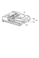
図1は、画像形成装置のシート搬送方向に沿った概略断面図である。図2は、画像読取装置の外観斜視図である。画像形成装置100は、装置本体100Aと、装置本体100Aの上部に設けられた画像読取装置400とで構成されている。画像読取装置400は、原稿載置面としてのプラテンガラス501に載置された原稿の画像を読み取る画像読取部500と、プラテンガラスに載置された原稿をプラテンガラスに押圧する原稿押圧体としての原稿供給装置600とで構成されている。原稿供給装置(Auto Document Feeder)600は、後述する支持機構300によって、プラテンガラスに対し、回動して開閉可能に画像読取部500に設けられている。原稿供給装置600は、閉めた状態で、原稿をプラテンガラスに押圧するようになっている。プラテンガラス501に押圧された原稿は、図1の左右方向(副走査方向)に移動する画像読取ユニット502に照射されて読み取られるようになっている。この読み方を固定読みと称する。
(Image forming device)
FIG. 1 is a schematic cross-sectional view of the image forming apparatus along the sheet conveyance direction. FIG. 2 is an external perspective view of the image reading apparatus. The
また、原稿供給装置600は、原稿積載トレイ601に載置された原稿Sをプラテンガラス501上の画像読取位置に搬送した後、原稿排出トレイ602に排出するようになっている。画像読取部500は、プラテンガラス501上の画像読取位置に送り込まれてくる原稿に図1の位置に停止している画像読取ユニットの光を照射して、原稿を読み取るようになっている。この読み方を流し読みと称する。
The
装置本体100Aは、画像読取部500からの画像情報に基づいて、普通紙やOHPシート等のシートに原稿を複写する(画像を形成する)ようになっている。画像形成装置100の装置本体100Aの下部には、各種サイズのシートPを収納した複数のシートカセット111(図には1つだけ示して他は省略)が着脱自在に装着されている。シートカセット111から給紙搬送ローラ105によって搬送されたシートは、画像形成部103の感光ドラム110の転写位置に送られる。感光ドラム110は、画像読取装置400からの画像情報に基づいたレーザスキャナ102のレーザを照射されて、潜像を形成され、その潜像が不図示の現像装置によりトナー現像されてトナー画像として形成される。トナー画像は、転写位置に搬送されるシートに転写されて、定着器106によって定着される。
The apparatus
シートは、片面に画像を形成されて両面に形成する必要が無い場合、排出ローラ対109によって、胴内排出トレイ112に排出される。シートは、両面に画像を形成される場合、スイッチバック搬送によって反転搬送されて、再送パス107を搬送され、再度、画像形成部103へ送り込まれる。画像形成部103でシートは、他方の面にトナー画像を転写され、そのトナー画像を定着器106で定着されて排出ローラ対109から胴内排出トレイ112に排出される。なお、シートは、シートカセット111からの給送のみならず、マルチトレイ108からも給送されるようになっている。
When an image is formed on one side and it is not necessary to form both sides, the sheet is discharged to the in-
以上説明した、画像読取装置400は、ユーザに選択された、固定読みと流し読みとの一方の読み方によって原稿を読み取るようになっているが、本願発明の画像読取装置は、両方の読み方の内、少なくとも、原稿を固定読み出来ればよい。このため、原稿押圧体として、図1、図2に示す原稿供給装置600の代わりに、図3(A)に示すように、原稿をプラテンガラス501に押圧する平板状の開閉蓋2を使用してもよく、原稿押圧体は、原稿供給装置600に限定されるものではない。
The
したがって、以下、原稿供給装置600の代わりに開閉蓋2を備えた画像読取装置700について説明するが、本発明は、原稿供給装置600を備えた画像読取装置400についても、適用することができる。
Therefore, the
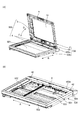
図3(A)は、開閉蓋2を起こして開いた画像読取装置700の外観斜視図である。図3(B)は、画像読取部500の外観斜視図である。開閉蓋2は、プラテンガラス501を覆う役目と外装の役目とをしている原稿台カバー9と、原稿台カバー9のプラテンガラス501側に粘着剤で貼り付けられた白色板10などで構成されている。白色板10は、原稿をプラテンガラス501に弾性的に押さえ付けることができるように、不図示のスポンジやゴムなどの弾性体を介して原稿台カバー9に設けられている。
FIG. 3A is an external perspective view of the
画像読取部500は、上部が開放された箱状の本体504と、本体の開放された上部に設けられたプラテンガラス501と、プラテンガラスの下方で、本体504内の左右方向(副走査方向)Aの向きに設けられた1対のガイド軸503と、で構成されている。さらに、画像読取部500は、固定読みのとき、ガイド軸503を案内にして副走査方向Aに移動しながら原稿を読み取る画像読取ユニット502も備えている。画像読取部500の奥部500aには、後述する開閉ヒンジ3が取付けられる断面方形状の縦孔としてのヒンジ取付け孔6と、後述する補助ヒンジ4のレバー41(図5、図6)が摺動する被摺動部としての被摺動面42とが形成されている。ヒンジ取付け孔6は、奥部500aの副走査方向Aの略中央に形成されている。被摺動面42は、ヒンジ取付け孔6から副走査方向Aに離れた両側に形成されている。画像読取部500は、ユーザが原稿をプラテンガラス501に載置して、開閉蓋2を閉めた後、画像読取ユニット502が1対のガイド軸503を案内にして副走査方向Aに移動することによって、原稿を固定読みするようになっている。なお、画像読取ユニット502は、図1に示す位置に停止して、原稿を流し読みすることもできるようになっている。
The
開閉蓋2は、副走査方向Aの中央に位置する第1の保持手段としての1つの開閉ヒンジ(蝶番)3と、開閉ヒンジ3の副走査方向Aの両側に位置する第2の保持手段としての補助ヒンジ4との協働によって、画像読取部500に、開閉自在に設けられている。すなわち、開閉ヒンジ3と補助ヒンジ4は、開閉蓋2を、プラテンガラス501に対して回動できるように、画像読取部500に回動自在に支持した支持機構300を構成している。
The open /
図3において、開閉ヒンジ3は、開閉蓋2が開閉できるように、開閉蓋2の奥部2aと画像読取部500の奥部500aとを後述する連結軸33(図4)によって軸支して接続している。奥部2a,500aとは、ユーザが画像形成装置100の前に立ったときの奥側の方のことである。図4において、開閉ヒンジ3は、図3(B)の断面方形状の縦孔としてのヒンジ取付け孔6に嵌合される角軸状の支柱31と、開閉蓋2にねじ止めされるヒンジ片32と、支柱31とヒンジ片32とを回動自在に連結する連結軸33とで構成されている。ヒンジ片32は、支柱31に対して、連結軸33を回動中心に閉方向Cと、開方向D方向とに回動するようになっている。なお、開閉ヒンジ3は、不図示のストッパによって、図4(B)の状態より、さらに、開方向Dには、回動しないようになっている。このため、開閉蓋2は、図3(A)の状態からさらに後方に倒れるのを防止されている。
In FIG. 3, the open /
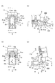
図5、図6において、補助ヒンジ4は、画像読取部500の奥部500aの上部に形成された被摺動面42と、開閉蓋2の奥部に設けられたレバー41とで構成されている。レバー41は、被摺動面42に当接して、開閉中の開閉蓋2を画像読取部500に支持するようになっている。このため、補助ヒンジ4は、開閉ヒンジ3と異なって、連結軸を有していない。
5 and 6, the auxiliary hinge 4 includes a sliding
レバー41は、ユーザが開閉蓋2を起こして、開いたとき、図3(A)、図5(D)に示すように、開閉蓋2とともに副走査方向Aに対して直交する主走査方向Bに回動して、下向きになるようになっている。また、レバー41は、ユーザが開閉蓋2を手前側に倒して、閉めたとき、図5(B)に示すようにプラテンガラス501の表面と略平行になるようになっている。レバー41は、図5に示すように、画像読取部500の奥部500aの主走査方向Bに沿って、長く形成された凹部43に進入している。凹部43の底面は、平らな被摺動面42である。レバー41の先端部(回動基端部)には、載置部としての被摺動面42に摺動自在に当接する摺動部41aになっている。摺動部41aには、図5(B)、(D)、図6(C)、(D)に示すように、開閉蓋2の開閉にともなって被摺動面42を摺動する、主走査方向Bに沿った円弧面41aaが形成されている。円弧面41aaの曲率中心41c(図6(D))は、開閉ヒンジ3の回動軸心である連結軸33(図4)と同心である。また、摺動部41aには、図5(A)、図6(C)、(D)に示すように、副走査方向Aに沿った円弧面41abが形成されている。円弧面41abの終端は、レバー41の副走査方向Aの両側に突出した突出部41acになっている。
When the user raises the opening /
凹部43は、図5(A)、(C)、図6(A)、(B)に示すように、奥部に円弧凹面43aが形成されている。また、凹部43は、主走査方向Bに沿った側壁43bが1対形成されている。
As shown in FIGS. 5A, 5 </ b> C, 6 </ b> A, and 6 </ b> B, the
図5(D)に示すように、補助ヒンジ4のレバー41は、円弧面41aaの部分が凹部43に進入し、被摺動面42に当接して、開閉ヒンジ3と共に、開閉蓋2を画像読取部500に支持している。補助ヒンジ4は、開閉ヒンジ3の両側に設けられているので、開閉蓋2が副走査方向Aに傾くのを防止している。また、レバー41の1対の突出部41acの両側には、僅かな隙間G(図5(C))を介して、凹部43の1対の側壁43bに対向している。因みに、隙間Gは、0.1mm〜0.2mmである。このため、開閉蓋2は、レバー41の突出部41acと、凹部43の側壁43bとによって構成される移動阻止部としての受け止め部44によって、副走査方向A(開閉ヒンジ3の回動軸心方向)への移動を阻止されるようになっている。
As shown in FIG. 5 (D), the
この状態で、開閉蓋2を手前側に倒す(閉方向Cに倒す)と、開閉蓋2は、支持機構300の開閉ヒンジ3と1対の補助ヒンジ4とを回動中心にして、回動する。このとき、レバー41の摺動部41aが被摺動面42上を摺動する。なお、レバー41と、被摺動面42が形成された画像読取部500は、摩擦係数の小さいPOM等の合成樹脂による成型品である。このため、レバー41が被摺動面42上を円滑に摺動するので、開閉蓋2は、速やかに閉められる。また、開閉蓋2の回転中、レバー41の両側の突出部41acと凹部43の側壁43bとが対向している。このため、開閉蓋2は、副走査方向Aへ移動するのを阻止されて、プラテンガラス501に載置された原稿をプラテンガラス501上で位置をずらすことなく、確実に押圧することができる。
In this state, when the opening /
開閉蓋2が閉められると、図5(A)、(B)に示すように、レバー41の円弧面41abが凹部43の円弧凹面43aに当接する。また、補助ヒンジ4は、開閉ヒンジ3の両側に設けられて、開閉ヒンジ3の両側でレバー41の円弧面41abが凹部43の円弧凹面43aに当接している。このため、補助ヒンジ4は、開閉蓋2がプラテンガラス501を閉めた状態で、プラテンガラス上で回転して位置がずれるのを阻止される。よって、開閉蓋2がプラテンガラス501に載置された原稿を、プラテンガラス501上で位置をずらすことなく、確実に押圧することができる。
When the opening /
なお、以上の説明では、レバー41に円弧面41aaが形成されている。しかし、図7(A)(B)に示す第2の保持手段としての補助ヒンジ104のように、レバー141の摺動部141aに円弧面を形成することなく、凹部143の被摺動部としての被摺動面142に、凹んだ円弧面142aを形成してもよい。この場合の円弧面142aの曲率中心141cも、開閉ヒンジ3の回動軸心である連結軸33と同心である。また、図示しないがレバーの摺動部と、被摺動面との両方に円弧面を形成してもよい。よって、円弧面は、摺動部と載置部としての被摺動面との互いに当接する少なくとも一方の面に形成されていればよい。この場合、いずれの円弧面においても、円弧面の曲率中心は、開閉ヒンジ3の回動軸心と同心である必要がある。
In the above description, the
さらに、図8に示す第2の保持手段としての補助ヒンジ204のように、レバー241に円弧面を形成することなく、先端部(回動基端部)241dに回転体としてのローラ244を設けてもよい。この場合、ローラ244の回転軸244aと開閉ヒンジ3の連結軸33とが、同心である必要がある。
Further, unlike the
さらに、被摺動面42は、凹部43に形成することなく、図9に示す第2の保持手段としての補助ヒンジ304のように、画像読取部500の奥部500aの平な上面500aaそのものを被摺動面として使用してもよい。この場合、レバー41は、図6に示すレバー41と同形である。また、図5に示す、円弧凹面43a、1対の側壁43bに相当する部分は、画像読取部500の奥部500aに突設した平面視コ字状の受け部材305に形成されている。
Further, the sliding
また、以上の説明では、補助ヒンジ4、104,204,304は、開閉ヒンジ3の両側にそれぞれ設けられているが、図10に示すように、開閉ヒンジ3と補助ヒンジ4(104,204,304)とを1つずつ、副走査方向Aに離間して配置してもよい。
In the above description, the auxiliary hinges 4, 104, 204, 304 are provided on both sides of the opening /
以上の画像読取装置は、原稿供給装置或いは開閉蓋を画像読取部に回動自在に支持するのに、従来複数使用していた開閉ヒンジの内、少なくとも1つの開閉ヒンジを残し、他を、原稿供給装置或いは開閉蓋を画像読取部に当接支持する構成にしてある。このため、画像読取装置400,700は、簡単な構成で、原稿供給装置600或いは開閉蓋2を画像読取部500に回動自在に支持されているので、構造や組立を簡単にして、コストを下げることができる。また、原稿供給装置或いは開閉蓋を画像読取部に当接支持するようにしてあるので、厚みのある原稿の場合、その当接支持する部分を浮き上がらせて、原稿供給装置或いは開閉蓋で原稿を画像読取部に密着させることができて、読取精度を向上させることができる。さらに、このような構成の画像読取装置を備えた画像形成装置も、コストを下げることができる。
In the above image reading apparatus, at least one open / close hinge among the open / close hinges conventionally used to rotatably support the document supply device or the opening / closing lid on the image reading unit is left, and the other is replaced with the original. The supply device or the opening / closing lid is configured to contact and support the image reading unit. For this reason, the
2:開閉蓋(原稿押圧体)、3:開閉ヒンジ(第1の保持手段)、4,104,204,304:補助ヒンジ(第2の保持手段)、41,141,241:レバー、41a,141a:回動基端部(摺動部)、41c:曲率中心、42:被摺動面(被摺動部、受け部)、142,500aa:被摺動面(被摺動部)、33:連結軸(回動軸心)、44:受け止め部(移動阻止部)、103:画像形成部、244:ローラ(回転体)、400,700:画像読取装置、500:画像読取部、501:プラテンガラス(原稿載置面)、600:原稿供給装置(原稿押圧体)、A:副走査方向、B:主走査方向、C:閉方向、D:開方向。 2: open / close lid (document pressing body), 3: open / close hinge (first holding means), 4, 104, 204, 304: auxiliary hinge (second holding means), 41, 141, 241: lever, 41a, 141a: rotation base end portion (sliding portion), 41c: center of curvature, 42: sliding surface (sliding portion, receiving portion), 142,500aa: sliding surface (sliding portion), 33 : Connection shaft (rotation axis), 44: receiving part (movement blocking part), 103: image forming part, 244: roller (rotating body), 400, 700: image reading device, 500: image reading part, 501: Platen glass (document placement surface), 600: document feeder (document pressing body), A: sub-scanning direction, B: main scanning direction, C: closing direction, D: opening direction.
Claims (14)
前記原稿載置面に載置された原稿を前記原稿載置面に押圧する原稿押圧体と、
前記原稿押圧体を前記画像読取部に軸支し、該原稿押圧体を前記原稿載置面に対して開閉可能に保持する第1の保持手段と、
前記原稿押圧体を前記原稿載置面に対して軸支することなく、前記第1の保持手段と共に前記原稿押圧体を前記原稿載置面に対して開閉可能に保持すると共に前記原稿押圧体の開閉に伴って回動し、該回動の回動中心は前記第1の保持手段の回動中心と実質的に同心である第2の保持手段と、を備えた、
ことを特徴とする画像読取装置。 An image reading unit for reading an image of the document placed on the document placement surface;
A document pressing body that presses the document placed on the document placement surface against the document placement surface;
Rotatably supported the document pressing member to the image reading unit, a first holding means for openably holding the document pressing member relative to the document placement surface,
Wherein Without pivotally supported with respect to the document pressing member the document placement surface of the document pressing member with openable holding the document pressing member relative to the document placement surface together with the first holding means A second holding means that rotates with opening and closing, the rotation center of the rotation being substantially concentric with the rotation center of the first holding means ;
An image reading apparatus.
前記原稿押圧体の回動基端部に設けられた摺動部と、
前記画像読取部に設けられて、前記原稿押圧体を前記原稿載置面に対して開閉可能とするように前記摺動部が摺動する被摺動部と、を備え、
前記第2の保持手段は、前記摺動部が前記被摺動部に摺動することで、前記原稿押圧体の開閉に伴って回動する、
ことを特徴とする請求項1に記載の画像読取装置。 The second holding means is
A sliding portion provided at a rotation base end portion of the document pressing body;
A sliding portion that is provided in the image reading portion and that slides so that the document pressing body can be opened and closed with respect to the document placement surface ;
The second holding means rotates with the opening and closing of the document pressing body by the sliding portion sliding on the sliding portion.
The image reading apparatus according to claim 1.
前記原稿押圧体に固定される固定部と、A fixing portion fixed to the document pressing body;
前記画像読取部に嵌合される嵌合部と、A fitting portion to be fitted to the image reading unit;
前記固定部と前記嵌合部とを回動可能に連結する連結軸と、を有し、A connecting shaft that rotatably connects the fixed portion and the fitting portion;
前記第2の保持手段は、前記摺動部と前記被摺動部の少なくとも一方に円弧面を有し、The second holding means has an arc surface on at least one of the sliding portion and the sliding portion,
前記円弧面の曲率中心は、前記連結軸と同心である、The center of curvature of the arc surface is concentric with the connecting shaft;
ことを特徴とする請求項2に記載の画像読取装置。The image reading apparatus according to claim 2.
前記原稿押圧体に固定される固定部と、
前記画像読取部に嵌合される嵌合部と、
前記固定部と前記嵌合部とを回動可能に連結する連結軸と、を有し、
前記第2の保持手段は、
前記原稿押圧体の回動基端部に設けられた回転体と、
前記画像読取部に設けられて、前記原稿押圧体を前記原稿載置面に対して開閉可能とするように前記回転体を受け止める受け部と、を備え、
前記回転体の回転中心は、前記連結軸と同心である、
ことを特徴とする請求項1に記載の画像読取装置。 The first holding means includes
A fixing portion fixed to the document pressing body;
A fitting portion to be fitted to the image reading unit;
A connecting shaft that rotatably connects the fixed portion and the fitting portion;
The second holding means is
A rotating body provided at a rotation base end of the document pressing body;
A receiving portion that is provided in the image reading portion and receives the rotating body so that the document pressing body can be opened and closed with respect to the document placement surface ;
Rotation center of the rotary body, which is the connecting shaft concentric,
The image reading apparatus according to claim 1.
ことを特徴とする請求項1乃至4のいずれか1項に記載の画像読取装置。 Provided on both sides of the second holding means, the document pressing member is provided with a movement preventing portion for preventing the moving to the turning axis direction of the first holding means,
The image reading apparatus according to any one of claims 1 to 4, characterized in that.
前記第1の保持手段は、前記第2の保持手段と前記第3の保持手段との間に設けられている、The first holding means is provided between the second holding means and the third holding means.
ことを特徴とする請求項1乃至5のいずれか1項に記載の画像読取装置。The image reading apparatus according to claim 1, wherein the image reading apparatus is an image reading apparatus.
前記画像読取装置によって読み取られた画像情報をシートに形成する画像形成部と、を備えた、
ことを特徴とする画像形成装置。 The image reading apparatus according to any one of claims 1 to 6 ,
An image forming unit that forms image information read by the image reading device on a sheet,
An image forming apparatus.
前記原稿載置面に載置された原稿を前記原稿載置面に押圧する原稿押圧体と、
前記原稿押圧体を前記画像読取部に軸支し、該原稿押圧体を前記原稿載置面に対して開閉可能に保持する第1の保持手段と、
前記原稿押圧体を前記原稿載置面に対して軸支することなく、前記原稿押圧体の開方向への回動中に前記原稿押圧体の荷重がかかった状態で前記第1の保持手段と共に前記原稿押圧体を保持する第2の保持手段と、を備えた、
ことを特徴とする画像読取装置。 An image reading unit for reading an image of the document placed on the document placement surface;
A document pressing body that presses the document placed on the document placement surface against the document placement surface;
A first holding unit that pivotally supports the document pressing member on the image reading unit and holds the document pressing member so as to be openable and closable with respect to the document placing surface;
Without supporting the document pressing body with respect to the document placement surface, together with the first holding means in a state where the document pressing body is loaded while the document pressing body is rotated in the opening direction. Second holding means for holding the original pressing body,
An image reading apparatus.
前記原稿押圧体の回動基端部に設けられた摺動部と、A sliding portion provided at a rotation base end portion of the document pressing body;
前記画像読取部に設けられて、前記原稿押圧体を前記原稿載置面に対して開閉可能とするように前記摺動部が摺動する被摺動部と、を備えた、A sliding portion that is provided in the image reading portion and that slides so that the document pressing body can be opened and closed with respect to the document placement surface;
ことを特徴とする請求項8に記載の画像読取装置。The image reading apparatus according to claim 8.
前記原稿押圧体に固定される固定部と、A fixing portion fixed to the document pressing body;
前記画像読取部に嵌合される嵌合部と、A fitting portion to be fitted to the image reading unit;
前記固定部と前記嵌合部とを回動可能に連結する連結軸と、を有し、A connecting shaft that rotatably connects the fixed portion and the fitting portion;
前記第2の保持手段は、The second holding means is
前記摺動部と前記被摺動部の少なくとも一方に円弧面を有し、At least one of the sliding part and the sliding part has an arc surface,
前記円弧面の曲率中心は、前記連結軸と同心である、The center of curvature of the arc surface is concentric with the connecting shaft;
ことを特徴とする請求項9に記載の画像読取装置。The image reading apparatus according to claim 9.
前記原稿押圧体に固定される固定部と、A fixing portion fixed to the document pressing body;
前記画像読取部に嵌合される嵌合部と、A fitting portion to be fitted to the image reading unit;
前記固定部と前記嵌合部とを回動可能に連結する連結軸と、を有し、A connecting shaft that rotatably connects the fixed portion and the fitting portion;
前記第2の保持手段は、The second holding means is
前記原稿押圧体の回動基端部に設けられた回転体と、A rotating body provided at a rotation base end of the document pressing body;
前記画像読取部に設けられて、前記原稿押圧体を前記原稿載置面に対して開閉可能とするように前記回転体を受け止める受け部と、を備え、A receiving portion that is provided in the image reading portion and receives the rotating body so that the document pressing body can be opened and closed with respect to the document placement surface;
前記回転体の回転中心は、前記連結軸と同心である、The rotation center of the rotating body is concentric with the connecting shaft.
ことを特徴とする請求項8に記載の画像読取装置。The image reading apparatus according to claim 8.
ことを特徴とする請求項8乃至11のいずれか1項に記載の画像読取装置。The image reading apparatus according to claim 8, wherein the image reading apparatus is an image reading apparatus.
前記第1の保持手段は、前記第2の保持手段と前記第3の保持手段との間に設けられている、The first holding means is provided between the second holding means and the third holding means.
ことを特徴とする請求項8乃至12のいずれか1項に記載の画像読取装置。The image reading apparatus according to claim 8, wherein the image reading apparatus is an image reading apparatus.
前記画像読取装置によって読み取られた画像情報をシートに形成する画像形成部と、を備えた、An image forming unit that forms image information read by the image reading device on a sheet,
ことを特徴とする画像形成装置。An image forming apparatus.
Priority Applications (3)
| Application Number | Priority Date | Filing Date | Title |
|---|---|---|---|
| JP2013227763A JP5951583B2 (en) | 2013-10-31 | 2013-10-31 | Image reading apparatus and image forming apparatus provided with image reading apparatus |
| US14/523,622 US9191542B2 (en) | 2013-10-31 | 2014-10-24 | Image reading apparatus and image forming apparatus provided with the same |
| CN201410602154.8A CN104601851B (en) | 2013-10-31 | 2014-10-31 | Image-reading device and the imaging device for being provided with image-reading device |
Applications Claiming Priority (1)
| Application Number | Priority Date | Filing Date | Title |
|---|---|---|---|
| JP2013227763A JP5951583B2 (en) | 2013-10-31 | 2013-10-31 | Image reading apparatus and image forming apparatus provided with image reading apparatus |
Publications (3)
| Publication Number | Publication Date |
|---|---|
| JP2015087676A JP2015087676A (en) | 2015-05-07 |
| JP2015087676A5 JP2015087676A5 (en) | 2015-07-30 |
| JP5951583B2 true JP5951583B2 (en) | 2016-07-13 |
Family
ID=52995111
Family Applications (1)
| Application Number | Title | Priority Date | Filing Date |
|---|---|---|---|
| JP2013227763A Expired - Fee Related JP5951583B2 (en) | 2013-10-31 | 2013-10-31 | Image reading apparatus and image forming apparatus provided with image reading apparatus |
Country Status (3)
| Country | Link |
|---|---|
| US (1) | US9191542B2 (en) |
| JP (1) | JP5951583B2 (en) |
| CN (1) | CN104601851B (en) |
Families Citing this family (7)
| Publication number | Priority date | Publication date | Assignee | Title |
|---|---|---|---|---|
| JP6075318B2 (en) | 2014-03-28 | 2017-02-08 | ブラザー工業株式会社 | Image forming apparatus |
| JP6128035B2 (en) | 2014-03-28 | 2017-05-17 | ブラザー工業株式会社 | Image forming apparatus |
| JP6402975B2 (en) * | 2014-06-30 | 2018-10-10 | セイコーエプソン株式会社 | Image reading device |
| JP6838449B2 (en) * | 2017-03-23 | 2021-03-03 | セイコーエプソン株式会社 | Document reader |
| JP6980564B2 (en) * | 2018-02-28 | 2021-12-15 | キヤノン株式会社 | Image reader and recording device |
| JP2019176338A (en) | 2018-03-28 | 2019-10-10 | キヤノン株式会社 | Image reading apparatus and image forming apparatus |
| JP2023047471A (en) * | 2021-09-27 | 2023-04-06 | 富士フイルムビジネスイノベーション株式会社 | Opening and closing device and image forming apparatus |
Family Cites Families (9)
| Publication number | Priority date | Publication date | Assignee | Title |
|---|---|---|---|---|
| US5552957A (en) * | 1994-09-09 | 1996-09-03 | International Business Machines Corporation | Portable computer field kit |
| JPH11119354A (en) * | 1997-10-16 | 1999-04-30 | Murata Mach Ltd | Original reader |
| JP4301141B2 (en) * | 2004-10-22 | 2009-07-22 | ブラザー工業株式会社 | Image forming apparatus |
| JP4713276B2 (en) * | 2005-08-29 | 2011-06-29 | リコープリンティングシステムズ株式会社 | Image forming apparatus |
| JP4306686B2 (en) * | 2006-02-27 | 2009-08-05 | ブラザー工業株式会社 | Image reading device |
| CN101193184A (en) * | 2006-11-21 | 2008-06-04 | 明基电通信息技术有限公司 | Pressing mechanism and its applied scanning device |
| JP5557176B2 (en) * | 2008-06-05 | 2014-07-23 | 株式会社ナチュラレーザ・ワン | Opening and closing device for document crimping plate and office equipment |
| JP5477565B2 (en) | 2009-09-30 | 2014-04-23 | 村田機械株式会社 | Image forming apparatus |
| JP5803416B2 (en) * | 2011-08-18 | 2015-11-04 | 日本電気株式会社 | Image reading device |
-
2013
- 2013-10-31 JP JP2013227763A patent/JP5951583B2/en not_active Expired - Fee Related
-
2014
- 2014-10-24 US US14/523,622 patent/US9191542B2/en not_active Expired - Fee Related
- 2014-10-31 CN CN201410602154.8A patent/CN104601851B/en not_active Expired - Fee Related
Also Published As
| Publication number | Publication date |
|---|---|
| CN104601851B (en) | 2018-01-09 |
| US9191542B2 (en) | 2015-11-17 |
| US20150116796A1 (en) | 2015-04-30 |
| CN104601851A (en) | 2015-05-06 |
| JP2015087676A (en) | 2015-05-07 |
Similar Documents
| Publication | Publication Date | Title |
|---|---|---|
| JP5951583B2 (en) | Image reading apparatus and image forming apparatus provided with image reading apparatus | |
| JP5100763B2 (en) | Document reading apparatus and image forming apparatus having the same | |
| JP2010028465A (en) | Covering device, image reading apparatus equipped with the covering device, and image recording apparatus provided with the image reading apparatus | |
| US11856151B2 (en) | Image reading device capable of relatively positioning document conveyance device and scanner housing using engaged portion and engaging portion, and image forming apparatus equipped with image reading device | |
| EP2819390B1 (en) | Image reading device, image forming apparatus, and optical unit | |
| JP6311638B2 (en) | Hinge structure and image forming apparatus having the same | |
| US9637330B2 (en) | Image forming apparatus | |
| JP3977213B2 (en) | Document cover hinge mechanism | |
| JP5938018B2 (en) | Image forming apparatus | |
| JP2009205087A (en) | Image forming apparatus | |
| US9219839B2 (en) | Image forming apparatus | |
| JP2005269450A (en) | Image reading apparatus | |
| JP4575178B2 (en) | Image forming apparatus | |
| US9444959B2 (en) | Image reading device and image forming apparatus including the same | |
| JP3885967B2 (en) | Image reading device | |
| JP2010066339A (en) | Mounting structure for document feeder and image forming apparatus incorporating this | |
| JP2013048392A (en) | Image reader and image forming apparatus equipped with the same | |
| JP2019092139A (en) | Image forming apparatus | |
| JP2014030144A (en) | Opening/closing device | |
| JP3854935B2 (en) | Image forming apparatus | |
| JP6936724B2 (en) | Document feeder, image reader and image forming device | |
| JP4630168B2 (en) | Document feeder and image reading apparatus | |
| JP4575523B1 (en) | Image reading apparatus and image forming apparatus | |
| JP5958777B2 (en) | Image forming apparatus and opening / closing apparatus | |
| JP6146297B2 (en) | Reader |
Legal Events
| Date | Code | Title | Description |
|---|---|---|---|
| A521 | Request for written amendment filed |
Free format text: JAPANESE INTERMEDIATE CODE: A523 Effective date: 20150611 |
|
| A621 | Written request for application examination |
Free format text: JAPANESE INTERMEDIATE CODE: A621 Effective date: 20150611 |
|
| A977 | Report on retrieval |
Free format text: JAPANESE INTERMEDIATE CODE: A971007 Effective date: 20151023 |
|
| A131 | Notification of reasons for refusal |
Free format text: JAPANESE INTERMEDIATE CODE: A131 Effective date: 20151110 |
|
| A521 | Request for written amendment filed |
Free format text: JAPANESE INTERMEDIATE CODE: A523 Effective date: 20160107 |
|
| TRDD | Decision of grant or rejection written | ||
| A01 | Written decision to grant a patent or to grant a registration (utility model) |
Free format text: JAPANESE INTERMEDIATE CODE: A01 Effective date: 20160607 |
|
| A61 | First payment of annual fees (during grant procedure) |
Free format text: JAPANESE INTERMEDIATE CODE: A61 Effective date: 20160608 |
|
| R150 | Certificate of patent or registration of utility model |
Ref document number: 5951583 Country of ref document: JP Free format text: JAPANESE INTERMEDIATE CODE: R150 |
|
| S533 | Written request for registration of change of name |
Free format text: JAPANESE INTERMEDIATE CODE: R313533 |
|
| R350 | Written notification of registration of transfer |
Free format text: JAPANESE INTERMEDIATE CODE: R350 |
|
| R250 | Receipt of annual fees |
Free format text: JAPANESE INTERMEDIATE CODE: R250 |
|
| R250 | Receipt of annual fees |
Free format text: JAPANESE INTERMEDIATE CODE: R250 |
|
| R250 | Receipt of annual fees |
Free format text: JAPANESE INTERMEDIATE CODE: R250 |
|
| R250 | Receipt of annual fees |
Free format text: JAPANESE INTERMEDIATE CODE: R250 |
|
| LAPS | Cancellation because of no payment of annual fees |