JP5950834B2 - Abnormality measuring device judgment system - Google Patents
Abnormality measuring device judgment system Download PDFInfo
- Publication number
- JP5950834B2 JP5950834B2 JP2013005077A JP2013005077A JP5950834B2 JP 5950834 B2 JP5950834 B2 JP 5950834B2 JP 2013005077 A JP2013005077 A JP 2013005077A JP 2013005077 A JP2013005077 A JP 2013005077A JP 5950834 B2 JP5950834 B2 JP 5950834B2
- Authority
- JP
- Japan
- Prior art keywords
- abnormality
- measuring device
- measurement
- measuring
- measuring instrument
- Prior art date
- Legal status (The legal status is an assumption and is not a legal conclusion. Google has not performed a legal analysis and makes no representation as to the accuracy of the status listed.)
- Expired - Fee Related
Links
Images


Description
この発明は、プラントにおける同じ被計測量(計測対象)を第1の計測器と第2の計測器とで計測し、上記第1の計測器の計測出力と上記第2の計測器の計測出力とを比較して上記計測器の異常を判定する異常計測器判定システムに関するものであり、例えば水処理プラントの各工程に設置された計測器の異常を判定し、計測器設備の保守を支援することができる異常計測器判定システムに適用できるものである。 This invention measures the same measured amount (measurement object) in a plant with the first measuring instrument and the second measuring instrument, and the measurement output of the first measuring instrument and the measurement output of the second measuring instrument. Is related to an abnormality measuring device determination system for determining abnormality of the above measuring device, for example, determining abnormality of a measuring device installed in each process of a water treatment plant, and supporting maintenance of the measuring device equipment The present invention can be applied to an abnormality measuring device determination system capable of performing the above.
一般的に、水処理プラントにおける異常計測器判定システムは計測器の計測値の上限値及び下限値を設定しトレンド異常についてのみ検知できるものが多かった。しかし、このように上下限値による異常判定では計測器そのものの異常を検知することができないことがあった。 In general, there are many abnormal measurement device determination systems in water treatment plants that can detect only trend abnormalities by setting an upper limit value and a lower limit value of measurement values of the measurement devices. However, there is a case where the abnormality of the measuring instrument itself cannot be detected by the abnormality determination based on the upper and lower limit values.
従来の異常計測器判定システムは以上の特徴があるため、計測器の点検が必要な場合や計測器が故障した場合にこれらの情報に遅れもしくは漏れが発生するリスクがある。また、点検や故障の情報を元に計測器の保守が必要となった場合、当該計測器と同種の計測器も同様に保守が必要な場合があり、その場合、同種計測器の設備情報を抽出する機能がなく作業の遅延や漏れのリスクがある。 Since the conventional abnormality measuring device determination system has the above characteristics, there is a risk that the information may be delayed or leaked when the measuring device needs to be inspected or when the measuring device breaks down. In addition, if maintenance of a measuring instrument is required based on information on inspection or failure, maintenance of a measuring instrument of the same type as that measuring instrument may be required as well. There is no function to extract and there is a risk of work delay and leakage.
この発明は上記のような課題を解決するためになされたものであり、「要点検」と「故障」とを区別して表示し、計測器の異常をより的確に検知してプラント運転員に点検や故障の情報をより適正な時期に展開できるようにすることを目的とするものである。 This invention has been made to solve the above problems, and Indicate the "principal Inspection" and "failure", inspect the plant operator to detect the abnormality of the instrument more precisely The purpose of this is to make it possible to develop information on failures and failures at a more appropriate time .
この発明に係る異常計測器判定システムは、第1の計測器の計測出力の変化率と上記第2の計測器の計測出力の変化率とを比較して上記計測器の異常を判定する異常計測器判定システムであって、上記計測出力はプラントにおける機器の定常運転時より起動時の方が大きくなり、上記第1の計測器の計測出力の変化率と上記第2の計測器の計測出力の変化率との差が閾値を超えたことを検出してこの検出に基づいて上記計測器の異常を判定し、この異常の判定の結果を出力した回数が所定回数となれば上記計測器は要点検であると表示し、上記異常の判定の結果を所定時間出力し続けると上記計測器は故障であると表示するものである。 The abnormality measuring device determination system according to the present invention compares the rate of change of the measurement output of the first measuring device with the rate of change of the measurement output of the second measuring device to determine the abnormality of the measuring device. The measurement output is greater at the time of startup than during steady operation of equipment in the plant, and the rate of change in the measurement output of the first measurement instrument and the measurement output of the second measurement instrument are If the difference between the rate of change exceeds the threshold, the abnormality of the measuring device is determined based on this detection, and the number of times that the result of the determination of the abnormality is output is a predetermined number, the measuring device is required. When the inspection is displayed, and the result of the abnormality determination is continuously output for a predetermined time, the measuring instrument displays a failure .
この発明は、第1の計測器の計測出力の変化率と上記第2の計測器の計測出力の変化率とを比較して上記計測器の異常を判定する異常計測器判定システムであって、上記計測出力はプラントにおける機器の定常運転時より起動時の方が大きくなり、上記第1の計測器の計測出力の変化率と上記第2の計測器の計測出力の変化率との差が閾値を超えたことを検出してこの検出に基づいて上記計測器の異常を判定し、この異常の判定の結果を出力した回数が所定回数となれば上記計測器は要点検であると表示し、上記異常の判定の結果を所定時間出力し続けると上記計測器は故障であると表示するので、「要点検」と「故障」とを区別して保守を行え、適正な保守が可能となり、プラント運転員に点検や故障の情報をより適正な時期に展開できる効果がある。 The present invention is an abnormality measuring device determination system that determines an abnormality of the measuring device by comparing the rate of change of the measuring output of the first measuring device and the rate of change of the measuring output of the second measuring device, The measurement output is larger at the time of start-up than during steady operation of the equipment in the plant, and the difference between the change rate of the measurement output of the first measurement device and the change rate of the measurement output of the second measurement device is a threshold value. Is detected and the abnormality of the measuring instrument is determined based on the detection, and if the number of times the result of the determination of the abnormality is output is a predetermined number, the measuring instrument is displayed as requiring inspection, If the result of the above-mentioned abnormality determination is output for a predetermined time, the above instrument will display a failure, so maintenance can be performed by distinguishing between “ needs to be inspected” and “failure”. Information on inspections and breakdowns can be expanded to employees at a more appropriate time There is a result.
実施の形態1.
以下、この発明の実施の形態1を図1〜図5により説明する。図1は異常計測器判定システムの全体構成の一例を示す図、図2は図1に例示の異常計測器判定システムの動作の例をフローチャートで示す図、図3は事例としてポンプが停止状態から起動しポンプが定常運転になるまでのポンプ流量のようなポンプ計測値の変化の一例を示す図、図4は事例としてポンプの状態変化における計測値の変化率の一例を示す図、図5は計測値変化率による異常判定の閾値の変化の一例を示す図である。
Embodiment 1 FIG.
Embodiment 1 of the present invention will be described below with reference to FIGS. FIG. 1 is a diagram showing an example of the overall configuration of the abnormality measuring device determination system, FIG. 2 is a flowchart showing an example of the operation of the abnormality measuring device determination system illustrated in FIG. 1, and FIG. FIG. 4 is a diagram showing an example of changes in pump measurement values such as the pump flow rate until the pump enters steady operation, FIG. 4 is a diagram showing an example of the change rate of measured values in the pump state change, and FIG. It is a figure which shows an example of the change of the threshold value of abnormality determination by a measured value change rate.
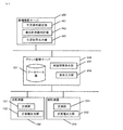
図1において、水処理プラントの各工程において、第1の計測器である主計測器(以下、「主計測器」と記す)100及び第2の計測器である副計測器(以下、「副計測器」と記す)200において水処理の各工程の計測対象(被計測量)を計測し計測値は出力されプラント監視サーバ300に蓄積される。設備情報管理サーバ400は、プラント監視サーバ300に蓄積された計測値とプラント監視サーバ300から設備情報サーバ400に入力された異常判定条件により計測器の異常を判定する。設備情報管理サーバ400が計測器を異常と判定したとき判定結果をプラント監視サーバ300に出力する。異常と判定された判定結果はプラント監視サーバ300において判定結果を表示し、プラント運転員に点検や故障の情報を展開しプラント運転員に保守を促すことができる。
In FIG. 1, in each process of the water treatment plant, a primary measuring instrument (hereinafter referred to as “main measuring instrument”) 100 as a first measuring instrument and a secondary measuring instrument (hereinafter referred to as “secondary measuring instrument”). The measurement target (measured amount) in each process of the water treatment is measured in 200, and the measured value is output and accumulated in the
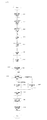
次に動作について図2を用いて説明する。
水処理プラントの各工程において、主計測器100は計測部101において水処理の各工程の計測対象を計測(ステップS101)し、計測値出力部102から計測値を出力(ステップS102)する。同様に、副計測器200は計測部201において水処理の各工程の計測対象を計測(ステップS101)し、計測値出力部202から計測値を出力(ステップS102)する。
Next, the operation will be described with reference to FIG.
In each process of the water treatment plant, the main
プラント監視サーバ300では、主計測器100及び副計測器200から出力された計測値を受信(ステップS301)しデータベース部301に蓄積(ステップS302)する。また、条件入力部303から異常な計測器であるか判定する条件を入力(ステップS303)し設備情報サーバ400へ送信(ステップS304)する。設備情報サーバ400で計測器の異常と判定され判定結果が出力(ステップS401)された場合、判定結果表示部302において判定結果を表示(ステップS305)する。
The
設備情報サーバ400では、条件入力部303から送信された異常な計器か判定する条件を判定条件設定部401に保存(ステップS402)し、異常計測器判定部402にて判定条件設定部401に保存された条件及びデータベース部301に蓄積された計測値を参照し、計測器が異常かを判定(ステップS403)する。計測器が異常と判定された場合、判定結果出力部403から判定結果表示部302へ判定結果を送信(ステップS401)する。
In the
上記実施の形態1では複数の計測器を水処理プラントの各工程に設置し、設備情報サーバ400に異常計測器判定部402を設けたので、プラントの運転よる計測値の変化よらず計測器の異常を容易に検知することができる。
In the first embodiment, a plurality of measuring instruments are installed in each process of the water treatment plant, and the abnormality measuring
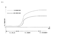
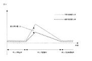
次いで、異常計測器判定部402の動作を図3、図4及び図5を用いて具体例で説明する。図3はポンプが停止状態から起動し、ポンプが定常運転になるまでのポンプ流量のようなポンプ計測値の変化を示す。図4は前記ポンプの状態変化における計測値の変化率を示したものである。図5は計測値変化率による異常判定の閾値の変化を示す。
Next, the operation of the abnormality measuring
ポンプ停止時は計測値が0であるため変化率も0となる。ポンプ起動時は計測値が大きく変化するため変化率は大きくなる。このとき、流量計の個体差や劣化等の要因により、主計測器100と副計測器200の計測値は異なるため変化率の差も大きくなる。ポンプが定常運転になると、計測値はほぼ一定になるため変化率はほぼ0となり変化率の差は小さくなる。
Since the measured value is 0 when the pump is stopped, the rate of change is also 0. Since the measured value changes greatly when the pump is started, the rate of change becomes large. At this time, due to factors such as individual differences and deterioration of the flowmeters, the measured values of the
2つの計測器の計測値の差、すなわち主計測器100の計測値と副計測器200の計測値との差、が条件入力部303より入力された閾値を超えたときいずれかの計測器が異常と判定する。
しかし、前記ポンプ起動時のように変化率の差が大きくなったとき、計測器が正常であっても2つの計測値の差は大きくなってしまう。このとき計測器を異常と判定する閾値を常に一定とすると、計測器が正常であるにも拘らず、計測値の差が閾値を超えてしまうため計測器を異常と誤判定してしまう恐れがある。
When the difference between the measured values of the two measuring instruments, that is, the difference between the measured value of the
However, when the difference in the rate of change becomes large as when the pump is activated, the difference between the two measured values becomes large even if the measuring instrument is normal. At this time, if the threshold value for determining that the measuring instrument is abnormal is always constant, the measurement value may exceed the threshold value even though the measuring instrument is normal, and the measuring instrument may be erroneously determined to be abnormal. is there.
そこで、図5に示すようにポンプ起動時に計測値変化率が大きくなったときは閾値を大きくすることにより、計測器が正常な場合の誤判定を避けることができる。一方で、ポンプが定常運転になると計測値の変化率は小さくなるため、閾値は小さくなる。 Therefore, as shown in FIG. 5, when the measured value change rate becomes large at the time of starting the pump, by increasing the threshold value, it is possible to avoid erroneous determination when the measuring instrument is normal. On the other hand, when the pump is in a steady operation, the change rate of the measured value is small, so the threshold value is small.
実施の形態2.
以下、この発明の実施の形態2を図6および図7により説明する。図6は異常計測器判定システムの全体構成の他の例を示す図、図7は図6に例示の異常計測器判定システムの動作の例をフローチャートで示す図である。
Embodiment 2. FIG.
A second embodiment of the present invention will be described below with reference to FIGS. FIG. 6 is a diagram illustrating another example of the overall configuration of the abnormality measuring device determination system, and FIG. 7 is a flowchart illustrating an example of the operation of the abnormality measuring device determination system illustrated in FIG.
実施の形態1では、主計測器100と副計測器200から得た計測値と、プラント監視サーバ300における計測器異常の条件設定及び判定結果の表示、設備情報サーバ400における計測器異常判定の関連付けについて述べたが、本実施の形態2では図6に例示のように、設備情報サーバ400に判定結果演算部404を設けることにより、判定結果出力部403が計測器異常と判断した判定結果を出力した回数を蓄積し、計測器異常と判断した判定結果を条件入力部303から入力した任意の回数出力(ステップS404)したとき主計測器100と副計測器200が要点検であると判定(ステップS405)し、判定結果をプラント監視サーバ300に送信(ステップS401)する。
In the first embodiment, the measurement values obtained from the
判定結果出力部403が計測器異常と判断した判定結果を条件入力部303から入力した任意の時間出力し続けた(ステップS404)とき主計測器100と副計測器200が故障であると判定(ステップS406)し、判定結果をプラント監視サーバ300に送信(ステップS401)する。判定結果表示部302では要点検及び故障であることを表示する。
When the determination
上記実施の形態2では、判定結果演算部404を設けたので、計測器の点検が必要か故障しているかを判定でき、プラント運転員に計測器の異常の種別を通知し、保守を促すことができる。
In the second embodiment, since the determination
実施の形態3.
以下、この発明の実施の形態3を図8および図9により説明する。図8は異常計測器判定システムの全体構成の更に他の例を示す図、図9は図8に例示の異常計測器判定システムの動作の例をフローチャートで示す図である。
Embodiment 3 FIG.
A third embodiment of the present invention will be described below with reference to FIGS. FIG. 8 is a diagram showing still another example of the overall configuration of the abnormality measuring device determination system, and FIG. 9 is a flowchart showing an example of the operation of the abnormality measuring device determination system illustrated in FIG.
実施の形態2では主計測器100及び副計測器200の要点検及び故障の判定におけるプラント監視サーバ300と設備情報サーバ400の関連付けについて述べたが、実施の形態2では主計測器100と副計測器200のどちらが異常であるかを判定できなかったが、本実施の形態3では図8に例示のように、異常計測器判定用計測器500を設け、判定結果演算部402にて3つの計測値のうち他の2つの計測値から条件入力部303から入力された条件以上の差を計測した計測器を要点検または故障と特定(ステップS407)することができる。
In the second embodiment, the association between the
上記実施の形態3では、水処理プラントの各工程に3つの計測器を設け、判定結果演算部402で以上判定結果を演算することにより、異常な計測器を特定することができ、プラント運転員に計測器の保守を促すことができる。
In Embodiment 3 described above, an abnormal measuring instrument can be identified by providing three measuring instruments in each process of the water treatment plant, and calculating the determination result by the determination
実施の形態4.
以下、この発明の実施の形態4を図10および図11により説明する。図10は異常計測器判定システムの全体構成の更に他の例を示す図、図11は図10に例示の異常計測器判定システムの動作の例をフローチャートで示す図である。
Embodiment 4 FIG.
A fourth embodiment of the present invention will be described below with reference to FIGS. FIG. 10 is a diagram illustrating still another example of the overall configuration of the abnormality measuring device determination system, and FIG. 11 is a flowchart illustrating an example of the operation of the abnormality measuring device determination system illustrated in FIG.
実施の形態3で計測器の要点検または故障を特定できることを述べたが、本実施の形態3では図10に例示のように、設備情報サーバ400に計測器のメーカや型番及び納入年度等の設備情報を登録した設備情報データベース部405を設け、異常と判定された計測器の設備情報を判定結果出力部403から送信(ステップS408)し判定結果表示部302に表示(ステップS305)することができる。
In the third embodiment, it has been described that the inspection or failure of the measuring instrument can be specified. In the third embodiment, as shown in FIG. 10, the
上記実施の形態4では、設備情報データベース部405を設け、異常と判定された計測器の設備情報を表示でき、プラント運転員に異常な計測器の保守や交換に関する情報を速やかに展開できる。
In the fourth embodiment, the facility
実施の形態5.
以下、この発明の実施の形態5を図12および図13により説明する。図12は異常計測器判定システムの全体構成の更に他の例を示す図、図13は図12に例示の異常計測器判定システムの動作の例をフローチャートで示す図である。
Embodiment 5 FIG.
The fifth embodiment of the present invention will be described below with reference to FIGS. FIG. 12 is a diagram illustrating still another example of the overall configuration of the abnormality measuring device determination system, and FIG. 13 is a flowchart illustrating an example of the operation of the abnormality measuring device determination system illustrated in FIG.
本実施の形態5では、図10に例示の実施の形態4に加えて、図12に例示のように、同種計測器抽出部406を設け、設備情報データベース部405に保存された同種設備情報407を抽出(ステップS409)し、異常と判定された計測器と同種の計測器の情報を判定結果出力部403から出力(ステップS401)し判定結果表示部302に表示(ステップS305)することができる。
In the fifth embodiment, in addition to the fourth embodiment illustrated in FIG. 10, as illustrated in FIG. 12, a similar
上記実施の形態5では、同種計測器抽出部406を設け、異常な計測器と同種の設備情報を設備情報データベース部405から抽出することができ、計測器の異常が発生する前にプラント運転員に点検や交換を促すことができる。
In the fifth embodiment, the same type of measuring
上述のことから明白なように、本発明の実施の形態1〜5は、以下のような技術的な特徴を有する。
特徴1:プラントにおける同じ被計測量を第1の計測器と第2の計測器とで計測し、上記第1の計測器の計測出力と上記第2の計測器の計測出力とを比較して上記計測器の異常を判定する異常計測器判定システムであって、上記第1の計測器の計測出力の変化率と上記第2の計測器の計測出力変化率との差に依存して上記計測器の異常を判定する異常計測器判定システムである。
特徴2:特徴1に記載の異常計測器判定システムにおいて、上記第1の計測器の計測出力と上記第2の計測器の計測出力との差が閾値を超えたことを検出しこの検出に基づいて上記計測器の異常を判定する異常計測器判定システムである。
特徴3:特徴2に記載の異常計測器判定システムにおいて、上記閾値の大きさが上記第1の計測器の計測出力の変化率と上記第2の計測器の計測出力変化率との差に依存していることを特徴とする異常計測器判定システムである。
特徴4:特徴1〜特徴3の何れか一に記載の異常計測器判定システムにおいて、上記第1の計測器の計測出力と上記第2の計測器の計測出力が蓄積されると共に上記第1の計測器の計測出力の変化率と上記第2の計測器の計測出力変化率との差に依存して上記計測器の異常を判定した結果が表示されるプラント監視サーバ、および上記第1の計測器の計測出力の変化率と上記第2の計測器の計測出力変化率との差に基づいて上記計測器の異常を判定する機能を有する設備情報サーバが設けられている異常計測器判定システムである。
特徴5:特徴1〜特徴4の何れか一に記載の異常計測器判定システムにおいて、上記計測器の異常を判定し当該異常が所定期間継続すると上記計測器が故障であると判定する異常計測器判定システムである。
特徴6:特徴4に記載の異常計測器判定システムにおいて、上記計測器の異常を判定し当該異常が所定期間継続すると上記計測器が故障であると判定する機能を設備情報サーバが有し、上記計測器が故障であると判定した結果が上記プラント監視サーバに表示される異常計測器判定システムである。
特徴7:特徴4〜特徴6の何れか一に記載の異常計測器判定システムにおいて、上記判定の条件が上記プラント監視サーバから上記設備情報サーバに設定される異常計測器判定システムである。
特徴8:特徴4〜特徴7の何れか一に記載の異常計測器判定システムにおいて、上記設備情報サーバに、上記計測器および上記計測器と同じ種類の他の計測器のそれぞれのメーカ名、型番、納入年月日の少なくとも一が設備情報として登録されている異常計測器判定システムである。
特徴9:特徴8に記載の異常計測器判定システムにおいて、上記プラント監視サーバに、上記計測器の異常の表示と併せて上記設備情報が表示される異常計測器判定システムである。
As is apparent from the above, the first to fifth embodiments of the present invention have the following technical features.
Feature 1: The same measured quantity in the plant is measured by the first measuring instrument and the second measuring instrument, and the measurement output of the first measuring instrument is compared with the measurement output of the second measuring instrument. An abnormality measurement device determination system for determining an abnormality of the measurement device, wherein the measurement depends on a difference between a change rate of measurement output of the first measurement device and a change rate of measurement output of the second measurement device. It is an abnormality measuring device determination system for determining abnormality of a device.
Feature 2: In the abnormality measuring device determination system according to Feature 1, it is detected that the difference between the measured output of the first measuring device and the measured output of the second measuring device exceeds a threshold value, and based on this detection An abnormality measuring device determination system for determining abnormality of the measuring device.
Feature 3: In the abnormality measuring device determination system according to Feature 2, the magnitude of the threshold depends on the difference between the rate of change in measurement output of the first meter and the rate of change in measurement output of the second meter This is an abnormality measuring device determination system.
Feature 4: In the abnormality measuring device determination system according to any one of features 1 to 3, the measurement output of the first measurement device and the measurement output of the second measurement device are accumulated and the first measurement device is stored. A plant monitoring server that displays a result of determining an abnormality of the measuring instrument depending on a difference between a measuring output change rate of the measuring instrument and a measuring output change rate of the second measuring instrument, and the first measurement An abnormality measuring device determination system provided with an equipment information server having a function of determining an abnormality of the measuring device based on a difference between a measuring output change rate of the measuring device and a measuring output change rate of the second measuring device. is there.
Feature 5: An abnormality measuring device according to any one of features 1 to 4, wherein the abnormality measuring device determines an abnormality of the measuring device and determines that the measuring device is faulty when the abnormality continues for a predetermined period. Judgment system.
Feature 6: In the abnormality measuring device determination system according to Feature 4, the facility information server has a function of determining abnormality of the measuring device and determining that the measuring device is faulty when the abnormality continues for a predetermined period of time, It is an abnormality measuring device determination system in which a result of determining that a measuring device is faulty is displayed on the plant monitoring server.
Feature 7: The abnormality measuring device determination system according to any one of features 4 to 6, wherein the determination condition is set from the plant monitoring server to the facility information server.
Feature 8: In the abnormality measuring device determination system according to any one of Features 4 to 7, the equipment information server includes the manufacturer name and model number of the measuring device and another measuring device of the same type as the measuring device. An abnormality measuring device determination system in which at least one of the delivery date is registered as equipment information.
Feature 9: The abnormality measuring device determination system according to feature 8, wherein the facility information is displayed on the plant monitoring server together with the display of the abnormality of the measuring device.
特徴10:水処理プラントの各工程に設置された流量計や汚泥濃度計等の各種「主計測器」と同一の計測対象を計測する同種の「副計測器」の二つの計測器から出力された計測値を蓄積するデータベース機能及び各種データ入出力機能及び表示機能を持った「プラント監視サーバ」と、前記「プラント監視サーバ」に蓄積された計測値から計測器の異常を検知する「設備情報サーバ」とを有する異常計測器判定システムにおいて、前記水処理プラントに設置された「主計測器」と「副計測器」と、前記「主計測器」と「副計測器」からの計測値を保存する前記「プラント監視サーバ」に保存された計測値を演算し計測器の異常を検知する「設備情報サーバ」と、前記「設備情報サーバ」から出力された判定結果を表示しかつ「設備情報サーバ」に異常な計測器の判定条件を設定することが可能な表示装置を備えた「プラント監視装置」を設けたことを特徴とする異常計測器判定システムである。
特徴11:特徴10において、異常計測器判定条件を設定した前記「設備情報サーバ」が計測器異常と判断した判定結果を出力した回数を蓄積し計測器異常と判断した判定結果をある任意の回数出力したときプラント運転員に前記「主計測器」と「副計測器」の点検を促す表示をし、計測器異常と判断した判定結果を一定時間出力し続けときプラント運転員に前記「主計測器」と「副計測器」が故障したことを表示する表示装置を備えた「プラント監視サーバ」と、計測器異常と判断した判定結果をある任意の回数出力したとき前記「主計測器」と「副計測器」の点検を促す判定結果を出力し計測器異常と判断した判定結果を一定時間出力し続けたとき前記「主計測器」と「副計測器」が故障であるという判定結果を出力する機能を備えた「設備情報サーバ」を設けたことを特徴とする異常計測器判定システムである。
特徴12:特徴11において、特徴10の水処理プラントに「主計測器」や「副計測器」と同一の計測対象を計測する同種の「異常検出用計測器」を設置し特徴11の「設備情報サーバ」を用いて特定の計測器の異常を検出し計測器の点検を促す判定結果及び計測器が故障であるという判定結果を出力する機能を持つ「設備情報サーバ」を備えた異常計測器判定システムである。
特徴13:特徴10〜 特徴12のいずれかに記載の「異常計測器判定システム」において、異常と判断された計測器のメーカや型番、納入年度等を登録した設備情報データベース機能を持った「設備情報サーバ」と、異常な計測器の設備情報データを表示する表示装置を備えた「プラント監視サーバ」を備えたことを特徴とする異常計測器判定システムである。
特徴14:特徴13において、異常計測器と同種の計測器を抽出しかつ異常計測器と同種の他の計測器設備情報データを出力する機能を持った「設備情報サーバ」と、異常と判定された計測器と同種の他の計測器の点検を促す表示をする表示装置を備えた「プラント監視サーバ」を備えたことを特徴とする異常計測器判定システムである。
Feature 10: Output from two measuring instruments of the same type of “sub-measurement device” that measures the same measurement object as various “main measurement devices” such as flow meters and sludge concentration meters installed in each process of the water treatment plant “Plant monitoring server” with a database function for storing measured values and various data input / output functions and display functions, and “facility information” for detecting abnormalities in measuring instruments from the measured values stored in the “plant monitoring server” In the abnormal measurement device determination system having a server, the measurement values from the “main measurement device” and “sub measurement device” installed in the water treatment plant, and the “main measurement device” and “sub measurement device” are obtained. The "facility information server" that calculates the measurement value stored in the "plant monitoring server" to be stored and detects an abnormality of the measuring instrument, and the determination result output from the "facility information server" are displayed and "equipment information" server It is abnormal instrument determination system characterized in that a "plant monitoring apparatus" having a display device capable of setting the abnormal instrument determination conditions.
Feature 11: In feature 10, the “equipment information server” in which an abnormality measuring device determination condition is set accumulates the number of times the determination result determined to be an abnormality of the measuring device is accumulated, and the determination result determined to be an abnormality of the measuring device is an arbitrary number of times. When it is output, it displays a message prompting the plant operator to check the “main measurement device” and “sub-measurement device”, and when the judgment result determined to be an abnormality of the measurement device continues to be output for a certain period of time, the “main measurement” is displayed to the plant operator. "Plant monitoring server" with a display device that displays that the "instrument" and "secondary measuring instrument" have failed, and the above-mentioned "main measuring instrument" when the determination result determined as measuring instrument abnormality is output a certain number of times When the judgment result that prompts the inspection of the “sub instrument” is output and the judgment result judged to be abnormal is continuously output for a certain time, the judgment result that the “main instrument” and the “sub instrument” are faulty is displayed. "With output function" Is abnormal instrument determination system characterized in that a Bei information server ".
Feature 12: In the feature 11, in the water treatment plant of the feature 10, the same kind of “measurement device for abnormality detection” that measures the same measurement object as the “main measurement device” and the “sub measurement device” is installed, and the “equipment for feature 11” An anomaly meter equipped with an “equipment information server” that has the function of detecting an abnormality of a specific measuring instrument using an “information server” and outputting a determination result that prompts the inspection of the measuring instrument and a determination result that the measuring instrument is faulty Judgment system.
Feature 13: “Facility 10” with the equipment information database function that registers the manufacturer, model number, delivery year, etc., of the measuring instrument determined to be abnormal in the “abnormality measuring instrument determination system” according to any one of characteristics 10 to 12. An abnormality measuring device determination system including an “information server” and a “plant monitoring server” including a display device that displays facility information data of abnormal measuring devices.
Feature 14: In feature 13, an “equipment information server” having a function of extracting a measuring device of the same type as the abnormal measuring device and outputting other measuring device facility information data of the same type as the abnormal measuring device is determined as abnormal. It is an abnormality measuring device determination system including a “plant monitoring server” including a display device that displays to prompt inspection of another measuring device of the same type as the measuring device.
なお、本発明は、その発明の範囲内において、各実施の形態を適宜、変形、省略することができる。
なお、各図中、同一符合は同一または相当部分を示す。
In the present invention, each embodiment can be appropriately modified or omitted within the scope of the invention.
In the drawings, the same reference numerals indicate the same or corresponding parts.
100 主計測器(第1の計測器)、200 副計測器(第2の計測器)、
300 プラント監視サーバ、 400 設備情報サーバ。
100 primary measuring instrument (first measuring instrument), 200 secondary measuring instrument (second measuring instrument),
300 plant monitoring server, 400 facility information server.
Claims (5)
上記計測出力はプラントにおける機器の定常運転時より起動時の方が大きくなり、上記第1の計測器の計測出力の変化率と上記第2の計測器の計測出力の変化率との差が閾値を超えたことを検出してこの検出に基づいて上記計測器の異常を判定し、この異常の判定の結果を出力した回数が所定回数となれば上記計測器は要点検であると表示し、上記異常の判定の結果を所定時間出力し続けると上記計測器は故障であると表示する
ことを特徴とする異常計測器判定システム。 An abnormality measuring device determination system that compares the change rate of the measurement output of the first measurement device with the change rate of the measurement output of the second measurement device to determine an abnormality of the measurement device,
The measurement output is larger at the time of start-up than during steady operation of the equipment in the plant, and the difference between the change rate of the measurement output of the first measurement device and the change rate of the measurement output of the second measurement device is a threshold value. Is detected and the abnormality of the measuring instrument is determined based on the detection, and if the number of times the result of the determination of the abnormality is output is a predetermined number, the measuring instrument is displayed as requiring inspection, The abnormality measuring device determination system, wherein if the abnormality determination result continues to be output for a predetermined time, the measuring device displays a failure .
上記起動時に上記変化率が大きくなったときは上記閾値を大きくし、上記定常運転時になると上記閾値は小さくなる
ことを特徴とする異常計測器判定システム。 In the abnormality measuring device determination system according to claim 1,
The abnormality measuring device determination system characterized in that the threshold value is increased when the rate of change becomes large at the time of startup, and the threshold value becomes smaller at the time of steady operation .
上記計測出力はプラントにおける機器の定常運転時より起動時の方が大きくなり、上記第1の計測器の計測出力の変化率と上記第2の計測器の計測出力の変化率との差が閾値を超えたことを検出してこの検出に基づいて上記計測器の異常を判定する設備情報サーバ、および異常の判定の結果を出力した回数が所定回数となれば上記計測器は要点検であると表示し、上記異常の判定の結果を所定時間出力し続けると上記計測器は故障であると表示するプラント監視サーバが設けられている
ことを特徴とする異常計測器判定システム。 In the abnormality measuring device determination system according to claim 1 or 2,
The measurement output is larger at the time of start-up than during steady operation of the equipment in the plant, and the difference between the change rate of the measurement output of the first measurement device and the change rate of the measurement output of the second measurement device is a threshold value. The equipment information server that detects the abnormality of the measuring instrument based on this detection, and the measuring instrument is in need of inspection if the number of times the abnormality determination result is output is a predetermined number of times. A system for determining an abnormality measuring device, comprising: a plant monitoring server for displaying and displaying that the measuring device is in failure when the result of the abnormality determination is continuously output for a predetermined time .
上記判定の条件が、上記プラント監視サーバから、上記設備情報サーバに設定される
ことを特徴とする異常計測器判定システム。 In the abnormality instrument determination system according to 請 Motomeko 3,
The abnormality measuring device determination system, wherein the determination condition is set from the plant monitoring server to the facility information server .
上記設備情報サーバに、上記計測器および上記計測器と同じ種類の他の計測器のそれぞれのメーカ名、型番、納入年月日の少なくとも一が設備情報として登録され、
上記プラント監視サーバに、上記計測器および上記計測器と同じ種類の他の計測器の上記設備情報が、上記要点検の表示および上記故障の表示と併せて表示される
ことを特徴とする異常計測器判定システム。 In the abnormality measuring device determination system according to claim 3 or claim 4 ,
In the equipment information server, at least one of the manufacturer name, model number, and delivery date of each of the measuring instrument and other measuring instruments of the same type as the measuring instrument is registered as equipment information.
The facility information of the measuring instrument and another measuring instrument of the same type as the measuring instrument is displayed on the plant monitoring server together with a display of the inspection required and a display of the failure. An anomaly measuring device judgment system.
Priority Applications (1)
| Application Number | Priority Date | Filing Date | Title |
|---|---|---|---|
| JP2013005077A JP5950834B2 (en) | 2013-01-16 | 2013-01-16 | Abnormality measuring device judgment system |
Applications Claiming Priority (1)
| Application Number | Priority Date | Filing Date | Title |
|---|---|---|---|
| JP2013005077A JP5950834B2 (en) | 2013-01-16 | 2013-01-16 | Abnormality measuring device judgment system |
Publications (3)
| Publication Number | Publication Date |
|---|---|
| JP2014137659A JP2014137659A (en) | 2014-07-28 |
| JP2014137659A5 JP2014137659A5 (en) | 2015-03-12 |
| JP5950834B2 true JP5950834B2 (en) | 2016-07-13 |
Family
ID=51415135
Family Applications (1)
| Application Number | Title | Priority Date | Filing Date |
|---|---|---|---|
| JP2013005077A Expired - Fee Related JP5950834B2 (en) | 2013-01-16 | 2013-01-16 | Abnormality measuring device judgment system |
Country Status (1)
| Country | Link |
|---|---|
| JP (1) | JP5950834B2 (en) |
Families Citing this family (2)
| Publication number | Priority date | Publication date | Assignee | Title |
|---|---|---|---|---|
| JP6736898B2 (en) * | 2016-02-02 | 2020-08-05 | 富士通株式会社 | Facility inspection support program, facility inspection support method, and information processing device |
| JP6904284B2 (en) * | 2018-03-12 | 2021-07-14 | オムロン株式会社 | Optical safety sensor |
Family Cites Families (4)
| Publication number | Priority date | Publication date | Assignee | Title |
|---|---|---|---|---|
| JPH08147031A (en) * | 1994-11-17 | 1996-06-07 | Meidensha Corp | Instrumentation signal abnormality detecting device |
| JP3651742B2 (en) * | 1998-01-21 | 2005-05-25 | 株式会社東芝 | Plant monitoring system |
| EP1154919B1 (en) * | 1999-02-18 | 2004-06-09 | Continental Teves AG & Co. oHG | Sensor system with monitoring device, notably for an esp system for vehicles |
| JP2002163015A (en) * | 2000-11-29 | 2002-06-07 | National Institute For Materials Science | System and method for diagnosing trouble in facility operation system and the like |
-
2013
- 2013-01-16 JP JP2013005077A patent/JP5950834B2/en not_active Expired - Fee Related
Also Published As
| Publication number | Publication date |
|---|---|
| JP2014137659A (en) | 2014-07-28 |
Similar Documents
| Publication | Publication Date | Title |
|---|---|---|
| CN109637680B (en) | Nuclear power station leakage monitoring alarm method and alarm system | |
| WO2020052147A1 (en) | Monitoring device fault detection method and apparatus | |
| EP3905263A1 (en) | Nuclear power plant leakage monitoring alarm method and alarm system | |
| JP5621967B2 (en) | Abnormal data analysis system | |
| JP2013073414A (en) | Sensor diagnostic device and sensor diagnostic method for plant | |
| JP5164954B2 (en) | Device diagnostic method and device diagnostic device | |
| JP2017088314A (en) | Equipment diagnostic apparatus, equipment diagnostic method, and equipment diagnostic system | |
| KR101351309B1 (en) | System and method of control equipment fault diagnosis using pattern recognition technology | |
| CN112729723A (en) | Intelligent gas remote monitoring and management method and system based on Internet of things and artificial intelligence, electronic equipment and computer storage medium | |
| JP5950834B2 (en) | Abnormality measuring device judgment system | |
| JP5792667B2 (en) | Sensor diagnostic device and sensor diagnostic method | |
| JP2014021577A (en) | Apparatus, system, method, and program for failure prediction | |
| KR101741112B1 (en) | System of correction for revising meter of automation facilities | |
| US20230230034A1 (en) | Systems and methods for automated wetstock management | |
| CN105137776B (en) | Metering automation terminal control accessory system | |
| WO2016174958A1 (en) | Water leak occurence position estimation device, system, and method | |
| JP6375200B2 (en) | Apparatus and method for detecting abnormal signs of computer system | |
| CN107924185B (en) | Method and system for maintaining field devices in a plant using automation technology | |
| US11002561B2 (en) | Gas meter management system | |
| CN103901873B (en) | Safety instrumented systems and PST start method | |
| JP2012014222A (en) | Sensor state determination device | |
| JP2014137659A5 (en) | ||
| WO2009119032A1 (en) | Operation deviation reporting device and operation deviation reporting method | |
| CN104316099B (en) | A kind of analog sensor monitoring method based on redundant data and system | |
| KR20180093351A (en) | Apparatus and Method for Detecting Sensing Error at the Sensing Point for the Thermal Efficiency of Facility |
Legal Events
| Date | Code | Title | Description |
|---|---|---|---|
| A521 | Written amendment |
Free format text: JAPANESE INTERMEDIATE CODE: A523 Effective date: 20150127 |
|
| A621 | Written request for application examination |
Free format text: JAPANESE INTERMEDIATE CODE: A621 Effective date: 20150127 |
|
| A977 | Report on retrieval |
Free format text: JAPANESE INTERMEDIATE CODE: A971007 Effective date: 20151222 |
|
| A131 | Notification of reasons for refusal |
Free format text: JAPANESE INTERMEDIATE CODE: A131 Effective date: 20160105 |
|
| A521 | Written amendment |
Free format text: JAPANESE INTERMEDIATE CODE: A523 Effective date: 20160208 |
|
| TRDD | Decision of grant or rejection written | ||
| A01 | Written decision to grant a patent or to grant a registration (utility model) |
Free format text: JAPANESE INTERMEDIATE CODE: A01 Effective date: 20160510 |
|
| A61 | First payment of annual fees (during grant procedure) |
Free format text: JAPANESE INTERMEDIATE CODE: A61 Effective date: 20160607 |
|
| R151 | Written notification of patent or utility model registration |
Ref document number: 5950834 Country of ref document: JP Free format text: JAPANESE INTERMEDIATE CODE: R151 |
|
| LAPS | Cancellation because of no payment of annual fees |