JP5950654B2 - Image display apparatus and control method thereof - Google Patents
Image display apparatus and control method thereof Download PDFInfo
- Publication number
- JP5950654B2 JP5950654B2 JP2012081183A JP2012081183A JP5950654B2 JP 5950654 B2 JP5950654 B2 JP 5950654B2 JP 2012081183 A JP2012081183 A JP 2012081183A JP 2012081183 A JP2012081183 A JP 2012081183A JP 5950654 B2 JP5950654 B2 JP 5950654B2
- Authority
- JP
- Japan
- Prior art keywords
- light emission
- light
- representative point
- pixel
- luminance
- Prior art date
- Legal status (The legal status is an assumption and is not a legal conclusion. Google has not performed a legal analysis and makes no representation as to the accuracy of the status listed.)
- Expired - Fee Related
Links
- 238000000034 method Methods 0.000 title claims description 27
- 239000004973 liquid crystal related substance Substances 0.000 claims description 20
- 238000003702 image correction Methods 0.000 claims description 16
- 238000002834 transmittance Methods 0.000 claims description 9
- 238000005286 illumination Methods 0.000 description 40
- 238000010586 diagram Methods 0.000 description 19
- 230000001629 suppression Effects 0.000 description 19
- 238000001514 detection method Methods 0.000 description 7
- 230000000694 effects Effects 0.000 description 2
- 230000006837 decompression Effects 0.000 description 1
- 238000005259 measurement Methods 0.000 description 1
Images


Classifications
-
- G—PHYSICS
- G09—EDUCATION; CRYPTOGRAPHY; DISPLAY; ADVERTISING; SEALS
- G09G—ARRANGEMENTS OR CIRCUITS FOR CONTROL OF INDICATING DEVICES USING STATIC MEANS TO PRESENT VARIABLE INFORMATION
- G09G5/00—Control arrangements or circuits for visual indicators common to cathode-ray tube indicators and other visual indicators
- G09G5/10—Intensity circuits
-
- G—PHYSICS
- G09—EDUCATION; CRYPTOGRAPHY; DISPLAY; ADVERTISING; SEALS
- G09G—ARRANGEMENTS OR CIRCUITS FOR CONTROL OF INDICATING DEVICES USING STATIC MEANS TO PRESENT VARIABLE INFORMATION
- G09G3/00—Control arrangements or circuits, of interest only in connection with visual indicators other than cathode-ray tubes
- G09G3/20—Control arrangements or circuits, of interest only in connection with visual indicators other than cathode-ray tubes for presentation of an assembly of a number of characters, e.g. a page, by composing the assembly by combination of individual elements arranged in a matrix no fixed position being assigned to or needed to be assigned to the individual characters or partial characters
- G09G3/34—Control arrangements or circuits, of interest only in connection with visual indicators other than cathode-ray tubes for presentation of an assembly of a number of characters, e.g. a page, by composing the assembly by combination of individual elements arranged in a matrix no fixed position being assigned to or needed to be assigned to the individual characters or partial characters by control of light from an independent source
- G09G3/3406—Control of illumination source
- G09G3/342—Control of illumination source using several illumination sources separately controlled corresponding to different display panel areas, e.g. along one dimension such as lines
- G09G3/3426—Control of illumination source using several illumination sources separately controlled corresponding to different display panel areas, e.g. along one dimension such as lines the different display panel areas being distributed in two dimensions, e.g. matrix
-
- G—PHYSICS
- G09—EDUCATION; CRYPTOGRAPHY; DISPLAY; ADVERTISING; SEALS
- G09G—ARRANGEMENTS OR CIRCUITS FOR CONTROL OF INDICATING DEVICES USING STATIC MEANS TO PRESENT VARIABLE INFORMATION
- G09G2320/00—Control of display operating conditions
- G09G2320/06—Adjustment of display parameters
- G09G2320/0626—Adjustment of display parameters for control of overall brightness
-
- G—PHYSICS
- G09—EDUCATION; CRYPTOGRAPHY; DISPLAY; ADVERTISING; SEALS
- G09G—ARRANGEMENTS OR CIRCUITS FOR CONTROL OF INDICATING DEVICES USING STATIC MEANS TO PRESENT VARIABLE INFORMATION
- G09G2360/00—Aspects of the architecture of display systems
- G09G2360/16—Calculation or use of calculated indices related to luminance levels in display data
-
- G—PHYSICS
- G09—EDUCATION; CRYPTOGRAPHY; DISPLAY; ADVERTISING; SEALS
- G09G—ARRANGEMENTS OR CIRCUITS FOR CONTROL OF INDICATING DEVICES USING STATIC MEANS TO PRESENT VARIABLE INFORMATION
- G09G3/00—Control arrangements or circuits, of interest only in connection with visual indicators other than cathode-ray tubes
- G09G3/20—Control arrangements or circuits, of interest only in connection with visual indicators other than cathode-ray tubes for presentation of an assembly of a number of characters, e.g. a page, by composing the assembly by combination of individual elements arranged in a matrix no fixed position being assigned to or needed to be assigned to the individual characters or partial characters
- G09G3/34—Control arrangements or circuits, of interest only in connection with visual indicators other than cathode-ray tubes for presentation of an assembly of a number of characters, e.g. a page, by composing the assembly by combination of individual elements arranged in a matrix no fixed position being assigned to or needed to be assigned to the individual characters or partial characters by control of light from an independent source
- G09G3/36—Control arrangements or circuits, of interest only in connection with visual indicators other than cathode-ray tubes for presentation of an assembly of a number of characters, e.g. a page, by composing the assembly by combination of individual elements arranged in a matrix no fixed position being assigned to or needed to be assigned to the individual characters or partial characters by control of light from an independent source using liquid crystals
Description
本発明は、画像表示装置及びその制御方法に関するものである。 The present invention relates to an image display device and a control method thereof.
液晶表示装置では、輝度を独立に制御可能な複数の発光ブロックからなるバックライト装置を備え、液晶パネルの表示領域をバックライト装置の各発光ブロックに対応する分割領域により分割し、画像信号に基づいて発光ブロック毎に輝度を制御する技術がある。各発光ブロックの輝度に基づいて各分割領域に対応する画像信号に画像処理を施して液晶パネルの透過率を制御することにより、コントラストの改善や消費電力低減の効果がある。このバックライトの輝度制御において、画像を適切に表示するためには、各画素に照明されるバックライトの輝度を正確に推測し、推測された輝度に基づいて液晶の透過率を制御する必要がある。 The liquid crystal display device includes a backlight device composed of a plurality of light emitting blocks whose brightness can be controlled independently, and the display area of the liquid crystal panel is divided into divided regions corresponding to the respective light emitting blocks of the backlight device, and is based on image signals. There is a technique for controlling the luminance for each light emitting block. By performing image processing on the image signal corresponding to each divided area based on the luminance of each light-emitting block and controlling the transmittance of the liquid crystal panel, there are effects of improving contrast and reducing power consumption. In this backlight brightness control, in order to display an image appropriately, it is necessary to accurately estimate the brightness of the backlight illuminated on each pixel and control the transmittance of the liquid crystal based on the estimated brightness. is there.
従来、各画素を照明するバックライトの輝度を推測する方法として、個々の発光ブロックが点灯したときの画素毎の輝度分布を示すデータを予め保存しておき、それらを重ね合わせることにより、画素毎の輝度を推測する方法があった。(例えば、特許文献1参照) Conventionally, as a method of estimating the luminance of the backlight that illuminates each pixel, data indicating the luminance distribution for each pixel when each light-emitting block is turned on is stored in advance, and the data is superimposed for each pixel. There was a way to guess the brightness of. (For example, see Patent Document 1)
また、バックライトの輝度を発光ブロック毎に推測し、それを線形補間することにより画素毎の輝度を推測する方法があった。(例えば、特許文献2参照) Further, there has been a method of estimating the luminance of each backlight by estimating the luminance of the backlight for each light emitting block and linearly interpolating it. (For example, see Patent Document 2)
しかしながら、上述した特許文献1の技術では、バックライトの発光ブロック数に比例する数だけ、各画素に対応する輝度分布データを必要とするので、大きなデータを予め保存しておく必要がある。そして、輝度推測の演算では、バックライトの発光ブロック数と同数の輝度分布データの重み付け加算を毎画素行う必要がある。そのため、バックライトの発光ブロック数が多い場合にはデータ量と演算量が膨大になるという課題があった。
However, since the technique of
また、上述した特許文献2の技術では、バックライトの輝度を発光ブロック単位で推測するので演算量は少ないが、バックライトの輝度分布は平面的ではないので、線形補間により得られた画素毎の推測輝度の誤差は大きい。そのため、その推測輝度に基づいて液晶の透過率を制御して表示した画像は、意図した画像からのひずみが大きく画質が低下するという問題があった。
In the technique of
そこで、本発明は、輝度を独立に制御可能な複数の発光ブロックからなるバックライト装置を備えた透過型の画像表示装置において、バックライトによる照明輝度の画素毎の推定演算量を抑えつつ表示画質の低下を抑制することを目的とする。 In view of this, the present invention provides a transmissive image display device having a backlight device composed of a plurality of light-emitting blocks whose luminance can be controlled independently. It aims at suppressing the fall of.
本発明は、発光を独立に制御可能な複数の発光ブロックを有する発光手段と、
前記発光手段からの光の透過率を画素値に基づいて個別に制御可能な複数の画素を有する表示パネルと、
入力画像データに基づいて、各発光ブロックの発光量を決定する決定手段と、
1つの発光ブロックを所定の発光量で発光させたときの、前記複数の発光ブロックに対応する複数の代表点における輝度を示す輝度データ、および、1つの発光ブロックを前記所定の発光量で発光させたときの前記代表点間の輝度の分布の形状を示す分布形状データを予め記憶する記憶手段と、
前記決定手段により決定された前記各発光ブロックの発光量および前記輝度データに示された前記複数の代表点の輝度に基づいて各代表点に対応する第1画素に対して決定され
る第1補正量と、前記第1補正量および前記分布形状データに基づいて前記代表点以外に対応する第2画素に対して決定される第2補正量とを用いて、前記入力画像データの各画素の画素値を補正する補正手段と、
を有することを特徴とする画像表示装置である。
The present invention comprises a light emitting means having a plurality of light emitting blocks capable of independently controlling light emission,
A display panel for have a plurality of pixels that can be controlled individually on the basis of the transmittance of light to the pixel values from said light emitting means,
Determining means for determining the light emission amount of each light emission block based on the input image data;
Luminance data indicating luminance at a plurality of representative points corresponding to the plurality of light emission blocks when one light emission block emits light with a predetermined light emission amount, and one light emission block is caused to emit light with the predetermined light emission amount. said storage means for previously storing a indicates to distribution shape data the Brightness of the distribution of the shape between the representative point when the,
Are determined for the first pixels corresponding to the representative point based on the luminance of the plurality of representative points the determined indicated in light emission amount and the luminance data of each light emitting block by said determining means
That a first correction amount, by using the second correction amount determined with respect to the second pixels corresponding to other than the representative point based on the first correction amount and the previous SL distribution shape data, the input and correcting means for correcting the pixel value of each pixel of Chikaraga image data,
It is an image display apparatus characterized by having.
本発明は、発光を独立に制御可能な複数の発光ブロックを有する発光手段と、
前記発光手段からの光の透過率を画素値に基づいて個別に制御可能な複数の画素を有する表示パネルと、
を有する画像表示装置の制御方法であって、
1つの発光ブロックを所定の発光量で発光させたときの、前記複数の発光ブロックに対応する複数の代表点における輝度を示す輝度データ、および、1つの発光ブロックを前記所定の発光量で発光させたたおきの前記代表点間の輝度の分布の形状を示す分布形状データを予め記憶する記憶手段から前記輝度データおよび前記分布形状データを読み込む工程と、
入力画像データに基づいて、各発光ブロックの発光量を決定する決定工程と、
前記決定工程により決定された前記各発光ブロックの発光量及び前記輝度データに示された前記複数の代表点の輝度に基づいて各代表点に対応する第1画素に対して決定される第1補正量と、前記第1補正量および前記分布形状データに基づいて前記代表点以外に対応する第2画素に対して決定される第2補正量とを用いて、前記入力画像データの各画素の画素値を補正する補正工程と、
を有することを特徴とする画像表示装置の制御方法である。
The present invention comprises a light emitting means having a plurality of light emitting blocks capable of independently controlling light emission,
A display panel for have a plurality of pixels that can be controlled individually on the basis of the transmittance of light to the pixel values from said light emitting means,
A method for controlling an image display device comprising:
One emission when the block was allowed to emit light at a predetermined light emission amount, luminance data indicating the luminance of the plurality of representative points corresponding to the plurality of light-emitting blocks, and, emitting a single light-emitting block in the predetermined light emission amount a step from the storage means for storing the shape of the bright degree of distribution between allowed the other every said representative points are shown to distribution shape data previously read the luminance data and the previous SL distribution shape data,
A determination step of determining the light emission amount of each light emission block based on the input image data;
First determined for the first pixels corresponding to the representative point based on the luminance of the light emission amount and the plurality of representative points shown in the luminance data of the respective light-emitting blocks determined by the determination step using a correction amount and a second correction amount determined with respect to the second pixels corresponding to other than the representative point based on the first correction amount and the previous SL distribution shape data, the input Chikaraga image A correction step of correcting the pixel value of each pixel of the data;
It is a control method of the image display apparatus characterized by having.
本発明によれば、輝度を独立に制御可能な複数の発光ブロックからなるバックライト装置を備えた透過型の画像表示装置において、バックライトによる照明輝度の画素毎の推定演算量を抑えつつ表示画質の低下を抑制することができる。 According to the present invention, in a transmissive image display device including a backlight device composed of a plurality of light-emitting blocks whose luminance can be controlled independently, display image quality is suppressed while suppressing an estimated calculation amount for each pixel of illumination luminance by the backlight. Can be suppressed.
(実施例1)
以下、本発明の実施例1に係る画像表示装置及びその制御方法について図面を参照して説明する。
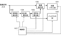
図1は、実施例1に係る画像処理装置の機能構成の一例を示す図である。
画像表示装置は、液晶パネル部101、バックライト部102、特徴量検出部103、発光量算出部104、伸長率算出部105、画像補正部106、及び制御部117で構成される。制御部117は、後述する各機能部の動作の制御を行う機能部である。
Example 1
Hereinafter, an image display apparatus and a control method thereof according to
FIG. 1 is a diagram illustrating an example of a functional configuration of the image processing apparatus according to the first embodiment.
The image display apparatus includes a liquid
液晶パネル部101は、液晶パネル部101に入力された画像信号に基づいて液晶を制御し、各画素の透過率を制御する透過型の表示パネルである。
The liquid
バックライト部102は、輝度を独立に制御可能な複数の発光ブロックを有する照明装置(バックライト装置)であり、液晶パネル部101を照明する。各発光ブロックの照明輝度は、発光量の制御値に基づいて制御される。例えば、バックライト部102は、照明範囲を水平方向にm分割、垂直方向にn分割した合計m×n個の発光ブロックで構成され、それらの発光ブロックの発光量が独立に制御される。
The
本実施例のバックライト輝度制御では、液晶パネル部101の表示領域をバックライト部102の各発光ブロックに対応する分割領域により分割し、各分割領域に表示される画像に対応する画像信号に応じて各分割領域に対応する発光ブロックの輝度を制御する。そして、各発光ブロックの輝度に応じて、対応する各分割領域の画像信号に対し画像処理を施す。このような制御をローカルディミング制御と称する。
In the backlight luminance control of the present embodiment, the display area of the liquid
ローカルディミング制御を行うことにより、例えば暗い画像が表示される分割領域に対応する発光ブロックの輝度が抑制され、当該分割領域の画像信号に対し画素値を伸長する画像処理が施され、当該分割領域における液晶パネルの透過率が高められる。これにより、当該分割領域における液晶パネルの表示輝度を低下させることなく、暗い画像の黒浮きの軽減とバックライト装置の消費電力の低減が可能になる。なお、液晶パネルの分割領域の各々とバックライトの発光ブロックとは、1対1に対応する同一の領域である必要はない。本実施例では、説明を簡単にするため、液晶パネルの各分割領域とバックライトの各発光ブロックは1対1に対応する領域であるとする。 By performing local dimming control, for example, the luminance of the light-emitting block corresponding to the divided area where a dark image is displayed is suppressed, and image processing for expanding the pixel value is performed on the image signal of the divided area. The transmittance of the liquid crystal panel is increased. As a result, it is possible to reduce darkening of dark images and reduce the power consumption of the backlight device without lowering the display brightness of the liquid crystal panel in the divided area. Note that each of the divided areas of the liquid crystal panel and the light emission block of the backlight do not have to be the same area corresponding one-to-one. In the present embodiment, in order to simplify the description, it is assumed that each divided area of the liquid crystal panel and each light emission block of the backlight are areas corresponding to one to one.
特徴量検出部103は、入力された画像信号を複数の分割領域により分割し、その分割領域毎に画像信号の特徴量を検出する。本実施例では、特徴量検出部103は、特徴量として各分割領域内の画像信号の画素値の最大値(最大画素値という)を検出する。検出された最大画素値は、発光量算出部104に出力される。
The feature
発光量算出部104は、特徴量検出部103で検出した分割領域毎の特徴量(ここでは最大画素値)に基づいて、発光ブロック毎の発光量の抑制率と発光量の制御値を算出し出力する。発光量の抑制率とは、可能な最大発光量に対する発光量の比率である。上記のように、ローカルディミング制御では、暗い画像が表示される分割領域に対応する発光ブロックの発光量を落とすことによってコントラストの向上と消費電力の低減を図るが、発光量の抑制率は、この発光量を落とす度合を示す。分割領域の全画素が、画素値に対応する輝度で表示されるためには、分割領域内の画素のうち最大画素値の画素をその画素値によって想定されている輝度で表示することができるように、その分割領域に対応する発光ブロックの照明輝度が設定されれば良い。
The light emission
そこで、発光量算出部104は、最大階調値(定数。例えば8ビットなら256)に対する分割領域内の最大画素値の比を標準照明輝度に乗算することにより、発光ブロック毎の照明輝度の目標値(目標照明輝度)を算出する。ここで、標準照明輝度とは、ローカルディミング制御(発光ブロック毎の輝度の抑制と分割領域毎の画素値の伸長)を行わずに画像表示する場合のバックライトの照明輝度を示す。標準照明輝度は、例えば、バックライト部102に可能な最大照明輝度とする。各発光ブロックの発光量は、他の発光ブロックに属する光源の発光の影響を受けるため、発光量の制御値はすべての発光ブロックの影響を考慮して決定する必要がある。そこで、発光量算出部104は、発光ブロック毎の発光量の制御値は次のように算出する。
Therefore, the light emission
まず、発光量算出部104は、各発光ブロックの照明輝度を対応する分割領域内の最大画素値を表示可能な輝度に制御するため、各発光ブロックについて、最大画素値を最大階調値で除算することにより仮抑制率を算出する。次に、発光量算出部104は、仮抑制率を標準照明輝度に乗算することにより、各発光ブロックの目標照明輝度を算出する。そして、発光量算出部104は、予め保存しておいた発光ブロック毎の代表点輝度データを仮抑制率で重み付け加算することにより、液晶パネルの表示領域内の所定の代表点における輝度の推測値である仮推測輝度を算出する。
First, the light emission
代表点輝度データは、発光ブロック毎に保存されており、ある発光ブロックの代表点輝度データは、その発光ブロックを標準照明輝度で発光させたときの代表点毎の輝度の情報を含む。本実施例の代表点輝度データは、全画素の輝度の情報ではなく、代表点のみの輝度の情報から構成されるため、データ量が少なくて済む。代表点毎の輝度は、測定や計算により予め求めて、代表点輝度データとして記憶手段に記憶しておく。 The representative point luminance data is stored for each light emitting block, and the representative point luminance data of a certain light emitting block includes information on luminance for each representative point when the light emitting block emits light with the standard illumination luminance. Since the representative point luminance data of this embodiment is composed of luminance information of only representative points, not information of luminance of all pixels, the data amount can be reduced. The luminance for each representative point is obtained in advance by measurement or calculation and stored in the storage means as representative point luminance data.
代表点(第一の代表点)としては、照明輝度の分布が山や谷になる位置の点や、輝度分布カーブの変曲点の点や、それらの点の近傍の点を選択するのが望ましい。これは、代表点は任意の位置の点における画素値の補正を行うための補正量としての伸長率の算出を行う際の基準となるからである(詳細は後述)。例えば、本実施例では、各発光ブロックの中心の点、及び、発光ブロック間の境界の点を代表点とする。照明輝度の分布と代表点の位置との関係を説明する図を図2に示す。 As the representative point (first representative point), it is possible to select a point at a position where the illumination luminance distribution becomes a mountain or a valley, a point of an inflection point of the luminance distribution curve, or a point in the vicinity of those points. desirable. This is because the representative point serves as a reference when calculating the expansion rate as a correction amount for correcting the pixel value at a point at an arbitrary position (details will be described later). For example, in this embodiment, the central point of each light emitting block and the boundary point between the light emitting blocks are used as representative points. FIG. 2 is a diagram for explaining the relationship between the distribution of illumination luminance and the position of the representative point.
図2は、5個の発光ブロックを1次元で模式的に示すとともに、各発光ブロックの発光による輝度分布及びそれらを重ね合わせて得られる5個の発光ブロック全体での輝度分布を模式的に示している。図2に示すように、個々の発光ブロック輝度分布は各発光ブロックの中心点をピークとして中心点から離れるほど減衰する曲線となる。図2は、発光ブロックの中心点と発光ブロック間の境界点を代表点とした例を示している。 FIG. 2 schematically shows the five light-emitting blocks in a one-dimensional manner, and schematically shows the luminance distribution due to the light emission of each light-emitting block and the luminance distribution in the entire five light-emitting blocks obtained by superimposing them. ing. As shown in FIG. 2, each light emission block luminance distribution is a curve that attenuates as the distance from the center point increases with the center point of each light emission block as a peak. FIG. 2 shows an example in which the center point of the light emission block and the boundary point between the light emission blocks are used as representative points.
図2に示すように、このように代表点を選ぶことで、照明輝度の分布が山と谷になる点や、照明輝度の分布カーブが変曲点となる点が、代表点となっていることがわかる。図2では各発光ブロックの輝度分布を連続曲線で示しているが、本実施例では、代表点における輝度のみを代表点輝度データとして予め記憶手段に保存しておく。すなわち、本実施例では、離散的な代表点輝度データを発光ブロック毎に保持することにより、データ量を抑える。 As shown in FIG. 2, by selecting representative points in this way, points where the distribution of illumination luminance becomes peaks and valleys, and points where the distribution curve of illumination luminance becomes an inflection point are representative points. I understand that. In FIG. 2, the luminance distribution of each light-emitting block is shown as a continuous curve, but in this embodiment, only the luminance at the representative point is stored in advance in the storage means as representative point luminance data. That is, in this embodiment, the data amount is suppressed by holding discrete representative point luminance data for each light emission block.
本実施例では、この考え方を2次元に拡張し、各発光ブロックの中心の点、発光ブロック間の境界の4隅の4つの頂点、及び発光ブロックの4つの辺上の4つの中間点の合計9点を代表点とする例を示す。発光ブロックと代表点の位置関係を説明する図を図3に示す。図3の例では、バックライトが、横方向にm個、縦方向にn個の合計m×n個の発光ブロックを有する場合、代表点の数は合計(2×m+1)×(2×n+1)個となる。なお、予め記憶手段に保存しておく発光ブロック毎の代表点輝度データは、(2×m+1)×
(2×n+1)個の代表点の位置に対応する輝度のデータがあればよく、全画素位置に対応した輝度のデータを保存しておくは必要ない。これにより代表点輝度データのデータ量を抑えることができる。図3の例では発光ブロックの形状は正方形だが、発光ブロックの形状は長方形でも良い。
In this embodiment, this idea is extended to two dimensions, and the sum of the center point of each light emitting block, the four vertices at the four corners of the boundary between the light emitting blocks, and the four intermediate points on the four sides of the light emitting block. An example with 9 points as representative points is shown. FIG. 3 is a diagram for explaining the positional relationship between the light emission block and the representative points. In the example of FIG. 3, when the backlight has a total of m × n light emitting blocks of m in the horizontal direction and n in the vertical direction, the number of representative points is the total (2 × m + 1) × (2 × n + 1). ) It becomes a piece. Note that the representative point luminance data for each light-emitting block stored in the storage means in advance is (2 × m + 1) ×
It is only necessary to have luminance data corresponding to the positions of (2 × n + 1) representative points, and it is not necessary to store luminance data corresponding to all pixel positions. Thereby, the data amount of representative point luminance data can be suppressed. In the example of FIG. 3, the shape of the light emitting block is square, but the shape of the light emitting block may be rectangular.
仮抑制率に基づいてバックライトを発光させると、照明輝度が不足する発光ブロックが発生することがある。また、逆に、照明輝度が過剰になることもある。発光ブロックの照明輝度が不足するとは、その発光ブロックに対応する分割領域内の最大画素値の画素において得られる照明輝度が、その画素を本来想定されていた輝度で表示するために必要な照明輝度に対して低いことを示す。 When the backlight is caused to emit light based on the temporary suppression rate, a light emission block having insufficient illumination luminance may occur. Conversely, the illumination brightness may be excessive. Insufficient illumination brightness of a light-emitting block means that the illumination brightness obtained in the pixel with the maximum pixel value in the divided area corresponding to the light-emitting block is the illumination brightness necessary for displaying that pixel at the originally assumed brightness. Is low.
そこで、発光量算出部104は、照明輝度が不足する発光ブロックが生じないように、抑制率を決定する。具体的には、発光量算出部104は、全ての代表点について目標照明輝度に対する仮推測輝度の割合を算出し、その中で最も小さいものを最小輝度比とする。そして、発光量算出部104は、発光ブロック毎の仮抑制率を最小輝度比で除算することにより、補正された発光ブロック毎の抑制率を算出する。発光量の制御値は、標準照明輝度の制御値に抑制率を乗算した値となる。
Therefore, the light emission
ここで、図4のフローチャートを用いて、発光ブロック毎の発光量の抑制率と発光量の制御値を算出するフローについて説明する。このフローチャートの処理は発光量算出部104により実行される。
Here, the flow for calculating the light emission amount suppression rate and the light emission amount control value for each light emission block will be described with reference to the flowchart of FIG. 4. The process of this flowchart is executed by the light emission
ステップ1において、発光量算出部104は、各発光ブロックについて、対応する分割領域内の最大画素値を最大階調値で除算することにより仮抑制率を算出する。
In
ステップ2において、発光量算出部104は、各発光ブロックについて、仮抑制率を標準照明輝度に乗算することにより、目標照明輝度を算出する。
In
ステップ3において、発光量算出部104は、予め保存しておいた発光ブロック毎の代表点輝度データを記憶手段から読み出し、仮抑制率で重み付け加算することにより、画面内の代表点における仮推測輝度を算出する。
In
ステップ4において、発光量算出部104は、全ての代表点について、目標照明輝度に対する代表点の仮推測輝度の割合を算出する。
In step 4, the light emission
ステップ5において、発光量算出部104は、目標輝度に対する仮推測輝度の割合のうちの最小値を最小輝度比とする。
In step 5, the light emission
ステップ6において、発光量算出部104は、各発光ブロックについて、仮抑制率を最小輝度比で除算することにより、発光ブロック毎の抑制率を算出する。
In step 6, the light emission
ステップ7において、発光量算出部104は、各発光ブロックについて、標準照明輝度の制御値に抑制率を乗算することにより、発光量の制御値を算出する。
In step 7, the light emission
伸長率算出部105は、各画素の画素値を補正するための補正量算出を行う。すなわち、伸長率算出部105は、発光量算出部104で算出された発光ブロック毎の発光量の抑制率と、予め保存しておいた代表点輝度データに基づいて、各代表点の画素値の伸長率と、補正点の画素値の伸長率を算出する。補正点は、代表点の伸長率を非線形補間するために代表点の間に配置された第二の代表点である。そして、伸長率算出部105は、各代表点に対応した代表点伸長率データと、各補正点に対応したカーブ伸長率データを出力する
。カーブ伸長率データとは、各補正点に対応した伸長率と各代表点に対応した伸長率とから算出される値である(後述)。発光ブロックと代表点と補正点の位置関係を説明する図を図5に示す。
The expansion
図5において、発光ブロックの中心の代表点を中心代表点、発光ブロックの4隅の代表点及び発光ブロックの4辺の中心の代表点を境界代表点としている。また、縦方向に隣接する2つの代表点の中心に位置する補正点を垂直補正点、横方向に隣接する2つの代表点の中心に位置する補正点を水平補正点としている。発光ブロックをm×n個に分割した場合は、代表点は(2×m+1)×(2×n+1)点、補正点は(8×m×n+2×m+2×n)点となる。本実施例では、予め保存しておく発光ブロック毎の代表点輝度データは、全ての代表点及び補正点における輝度のデータからなる。全画素における輝度のデータではなく離散的な位置における輝度のデータのみのため、代表点輝度データのデータ量が少なくて済む。 In FIG. 5, the central representative point of the light emitting block is the central representative point, the representative points at the four corners of the light emitting block, and the representative points at the center of the four sides of the light emitting block are the boundary representative points. A correction point located at the center of two representative points adjacent in the vertical direction is a vertical correction point, and a correction point located at the center of two representative points adjacent in the horizontal direction is a horizontal correction point. When the light emitting block is divided into m × n, the representative points are (2 × m + 1) × (2 × n + 1) points, and the correction points are (8 × m × n + 2 × m + 2 × n) points. In this embodiment, the representative point luminance data for each light emission block stored in advance is composed of luminance data at all representative points and correction points. Since only the luminance data at discrete positions, not the luminance data for all pixels, the amount of representative point luminance data can be reduced.
伸長率算出部105は、発光量算出部104の動作で説明した処理と同様に、予め保存しておいた代表点輝度データを抑制率で重み付けして加算することにより、各代表点と各補正点の推測輝度を算出する。次に、伸長率算出部105は、標準照明輝度を推測輝度で除算することにより、各代表点と各補正点の画素値の伸長率を算出する。そして、伸長率算出部105は、算出した各代表点の伸長率を、代表点伸長率データとして出力する。
Similarly to the process described in the operation of the light emission
また、伸長率算出部105は、算出した各補正点の伸長率と、それに隣接する2つの代表点の伸長率の平均値と、の差を、各補正点のカーブ伸長率データとして出力する。補正点の伸長率GC、2つの代表点の伸長率をそれぞれGP1、GP2とすると、カーブ伸長率データCGは次の計算式で算出される。水平補正点のカーブ伸長率を水平カーブ伸長率、垂直補正点のカーブ伸長率を垂直カーブ伸長率と呼ぶ。
CG=GC−(GP1+GP2)/2 ・・・(1)
Further, the expansion
CG = GC− (GP1 + GP2) / 2 (1)
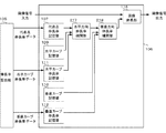
画像補正部106は、伸長率算出部105で算出された代表点伸長率データとカーブ伸長率データに基づいて、入力された画像信号の各画素の画素値を伸長した伸長画像信号(補正画像信号)を出力する。画像補正部106の機能構成の一例を図6に示す。
The
画像補正部106は、代表点伸長率記憶部107、線形伸長率補間部108、水平カーブ記憶部109、垂直カーブ記憶部110、水平カーブ伸長率記憶部111、垂直カーブ伸長率記憶部112、水平非線形伸長率補間部113、垂直非線形伸長率補間部114、伸長率加算部115、画像伸長部116で構成される。
The
代表点伸長率記憶部107は、各代表点の伸長率を代表点伸長率データとして保存する。そして、代表点伸長率記憶部107は、注目画素(伸長率を算出する対象画素)の位置に基づいて、その画素を囲む4つの代表点の代表点伸長率データを出力する。
The representative point extension
線形伸長率補間部108は、注目画素と注目画素を囲む4つの代表点との相対的な位置関係に基づいて、代表点伸長率記憶部107から出力される4つの代表点伸長率データを線形補間演算することにより、線形伸長率を算出し出力する。具体的には、注目画素の中心代表点からの水平画素数をDPh、垂直画素数をDPv、水平方向の代表点間画素数をPWh、垂直方向の代表点間画素数をPWvとすると、線形伸長率補間部108は、注目画素の線形伸長率Glnを以下の式により求める。
Gln=(1−DPv/PWv)
×((1−DPh/PWh)×Gc+DPh/PWh×Gh)
+(DPv/PWv)
×((1−DPh/PWh)×Gv+DPh/PWh×Ghv)
・・・(2)
ここで、Gcは中心代表点の代表点伸長率データ、Ghは中心代表点に水平方向に隣接する境界代表点の代表点伸長率データである。また、Gvは中心代表点に垂直方向に隣接する境界代表点の代表点伸長率データ、Ghvは中心代表点から斜め方向に隣接する境界代表点の代表点伸長率データである。注目画素とそれを囲む4つの代表点との相対位置と伸長率データの関係を説明する図を図7に示す。
The linear expansion
Gln = (1-DPv / PWv)
× ((1-DPh / PWh) × Gc + DPh / PWh × Gh)
+ (DPv / PWv)
× ((1-DPh / PWh) × Gv + DPh / PWh × Ghv)
... (2)
Here, Gc is representative point extension rate data of the center representative point, and Gh is representative point extension rate data of the boundary representative point adjacent to the center representative point in the horizontal direction. Gv is representative point extension rate data of boundary representative points adjacent to the center representative point in the vertical direction, and Ghv is representative point extension rate data of boundary representative points adjacent to the center representative point in the oblique direction. FIG. 7 is a diagram for explaining the relationship between the relative position between the pixel of interest and the four representative points surrounding it and the expansion rate data.
水平カーブ記憶部109は、水平方向に隣接する代表点間の輝度分布の水平方向の形状を近似的に示す非線形カーブ(水平カーブという)のデータ(輝度分布データ)を保存する。水平カーブは、例えば、一つの発光ブロックを発光させた場合の輝度分布に基づき次のように求める。すなわち、中心代表点からそれに対し水平方向に隣接する境界代表点までの輝度分布形状(一般に非線形の分布)と、中心代表点における輝度から境界代表点における輝度までの輝度がリニアに変化すると仮定した場合の輝度分布形状(線形)と、の差分とする。
The horizontal
この差分値の中心代表点から境界代表点までの輝度分布形状を示すのが、水平カーブである。すなわち、水平カーブは、中心代表点からそれに水平方向に隣接する境界代表点までの各点(画素)について値が定まった関数であり、中心代表点からの画素数の関数として表すことができる。このように求めた水平カーブの値は、境界代表点及び中心代表点で0となる。水平カーブの値は、中心代表点から境界代表点までの間の輝度分布形状が、常に上に凸の場合は各点で正の値となり、常に下に凸の場合は各点で負の値となる。 A horizontal curve shows the luminance distribution shape from the center representative point of the difference value to the boundary representative point. That is, the horizontal curve is a function in which a value is determined for each point (pixel) from the center representative point to the boundary representative point adjacent in the horizontal direction, and can be expressed as a function of the number of pixels from the center representative point. The horizontal curve value thus obtained is 0 at the boundary representative point and the central representative point. The value of the horizontal curve is a positive value at each point when the luminance distribution shape between the center representative point and the boundary representative point is always convex upward, and a negative value at each point when the convex shape is always downward. It becomes.
水平カーブは中心代表点から境界代表点までの全ての位置における値のデータを有するものとし、例えば、中心代表点からの画素数DPhの関数として表すことができる。本実施例では、中心代表点と境界代表点の間の水平補正点における水平カーブの値が1となるように正規化した水平カーブを水平カーブ記憶部109に保存しておくものとする。そして、水平カーブ記憶部109は、注目画素の位置と水平方向に隣接する2つの代表点の、水平方向の相対位置に基づいて、水平カーブデータを出力する。
The horizontal curve has data of values at all positions from the central representative point to the boundary representative point, and can be expressed as a function of the number of pixels DPh from the central representative point, for example. In this embodiment, it is assumed that a horizontal curve normalized so that the value of the horizontal curve at the horizontal correction point between the center representative point and the boundary representative point is 1 is stored in the horizontal
水平カーブ伸長率記憶部111は、水平補正点のカーブ伸長率データを保存する。そして、水平カーブ伸長率記憶部111は、注目画素の位置に基づいて、注目画素に隣接する2つの水平補正点のカーブ伸長率データを出力する。ここで、注目画素に隣接する2つの水平補正点とは、注目画素を囲む4つの代表点のうち、中心代表点とそれに水平方向に隣接する境界代表点との間の水平補正点と、それらの代表点以外の2つの境界代表点の間の水平補正点である。
The horizontal curve expansion
水平非線形伸長率補間部113は、水平カーブ伸長率記憶部111から出力される2つの水平補正点の水平カーブ伸長率データを、中心代表点に対する注目画素の垂直方向の相対位置に基づいて線形補間する。そして、補間した水平カーブ伸長率データを、水平カーブ記憶部109から出力される水平カーブデータに乗算し、水平非線形伸長率として出力する。水平カーブデータが非線形の輝度分布に対応するので、ここでは、水平カーブデータに水平カーブ伸長率データを乗算する演算により非線形補間演算を行っていることになる。具体的には、注目画素の中心代表点からの垂直画素数をDPv、垂直方向の代表点間画素数をPWv、水平カーブデータをCVhとすると、水平非線形伸長率Gnlhは以下の式より求められる。
Gnlh=CVh
×((1−DPv/PWv)×CGch+DPv/PWv×CGh)
・・・(3)
ここで、図7に示すように、CGchは水平方向に隣接する中心代表点と境界代表点の間の水平補正点のカーブ伸長率データ、CGhは水平方向に隣接する境界代表点と境界代表点の間の水平補正点のカーブ伸長率データである。
The horizontal nonlinear expansion
Gnlh = CVh
× ((1-DPv / PWv) × CGch + DPv / PWv × CGh)
... (3)
Here, as shown in FIG. 7, CGch is the curve expansion rate data of the horizontal correction point between the center representative point and the boundary representative point adjacent in the horizontal direction, and CGh is the boundary representative point and the boundary representative point adjacent in the horizontal direction. It is the curve expansion rate data of the horizontal correction point between.
垂直カーブ記憶部110は、垂直方向に隣接する代表点間の輝度変化の垂直方向の形状を近似的に示す非線形カーブ(垂直カーブという)のデータを保存する。基本的な動作は水平カーブ記憶部109と同様である。また、水平方向と垂直方向の非線形カーブが同じで良い場合は、水平カーブ記憶部109と垂直カーブ記憶部110は共通化してもよい。
The vertical
垂直カーブ伸長率記憶部112は、垂直補正点のカーブ伸長率データを保存する。基本的な動作は、水平カーブ伸長率記憶部111と同じである。
The vertical curve expansion
垂直非線形伸長率補間部114は、垂直カーブ伸長率記憶部112から出力される2つの垂直補正点の垂直カーブ伸長率データを、中心代表点に対する注目画素の水平方向の相対位置に基づいて線形補間する。そして、補間した垂直カーブ伸長率データを、垂直カーブ記憶部110から出力される垂直カーブデータに乗算し、垂直非線形伸長率として出力する。具体的には、注目画素の中心代表点からの水平画素数をDPh、水平方向の代表点間画素数をPWh、垂直カーブデータをCVvとすると、垂直非線形伸長率Gnlvは以下の式より求められる。
Gnlv=CVv
×((1−DPh/PWh)×CGcv+DPh/PWh×CGv)
・・・(4)
ここで、図7に示すように、CGcvは垂直方向に隣接する中心代表点と境界代表点の間の垂直補正点のカーブ伸長率データ、CGvは垂直方向に隣接する境界代表点と境界代表点の間の垂直補正点のカーブ伸長率データである。
The vertical nonlinear expansion
Gnlv = CVv
× ((1-DPh / PWh) × CGcv + DPh / PWh × CGv)
... (4)
Here, as shown in FIG. 7, CGcv is the curve expansion rate data of the vertical correction point between the center representative point and the boundary representative point adjacent in the vertical direction, and CGv is the boundary representative point and the boundary representative point adjacent in the vertical direction. It is the curve expansion rate data of the vertical correction point between.
伸長率加算部115は、線形伸長率補間部108から出力される線形伸長率Glnと、水平非線形伸長率補間部113から出力される水平非線形伸長率Gnlhと、垂直非線形伸長率補間部114から出力される垂直非線形伸長率Gnlvとを加算する。これにより、伸長率加算部115は、画素毎の伸長率Gpixを算出し、出力する。具体的には、画素毎の伸長率Gpixは、以下の式により求められる。
Gpix=Gln+Gnlh+Gnlv ・・・(5)
The expansion
Gpix = Gln + Gnlh + Gnlv (5)
画像伸長部116は、画像信号の各画素値に、画素毎の伸長率を乗算し、補正した画像信号を出力する。
The
図8に、実施例1に係る本発明による補間を説明する図を示す。図の例は、説明を簡単にするため、代表点を水平方向に結ぶ線上に注目画素がある場合の例である。図に示すように、伸長率は、代表点と補正点上の画素では推測輝度に基づいて算出された値(標準照明輝度を推測輝度で除した値)となる。代表点と補正点との間の画素では、1つの発光ブロックを発光させたときの輝度分布を近似したカーブを用いて非線形補間により算出された値となる。 FIG. 8 is a diagram for explaining interpolation according to the present invention according to the first embodiment. The example in the figure is an example in which the pixel of interest is on a line connecting the representative points in the horizontal direction for the sake of simplicity. As shown in the figure, the expansion rate is a value calculated based on the estimated luminance (a value obtained by dividing the standard illumination luminance by the estimated luminance) for the pixels on the representative point and the correction point. In the pixel between the representative point and the correction point, the value is calculated by nonlinear interpolation using a curve that approximates the luminance distribution when one light emitting block emits light.
以上のように、本発明によれば、代表点と補正点のみの照明輝度を推測し、それらの推測輝度に基づいて照明輝度の分布を近似したカーブで画素毎の画素値の伸長率を算出するので、少ない計算量で精度の高いバックライト輝度制御ができる。 As described above, according to the present invention, the illumination luminance of only the representative point and the correction point is estimated, and the pixel value expansion rate for each pixel is calculated using a curve that approximates the illumination luminance distribution based on the estimated luminance. Therefore, highly accurate backlight luminance control can be performed with a small amount of calculation.
(実施例2)
以下、本発明の実施例2に係る画像表示装置及びその制御方法について図面を参照して説明する。実施例1では、線形伸長率と非線形伸長率を個別に算出し、それを加算することにより画素毎の伸長率を算出する方法について説明した。本実施例では、代表点伸長率と補正点伸長率から、直接的に画素毎の伸長率を算出する方法について説明する。
(Example 2)
Hereinafter, an image display apparatus and a control method thereof according to
実施例2に係る画像処理装置の機能構成は実施例1と同じである。
液晶パネル部101、バックライト部102、特徴量検出部103、発光量算出部104の動作は実施例1と同じである。
The functional configuration of the image processing apparatus according to the second embodiment is the same as that of the first embodiment.
The operations of the liquid
伸長率算出部105における、代表点とその間に位置する補正点の画素値の伸長率を算出する処理、代表点伸長率データの生成方法は実施例1と同じである。実施例2の伸長率算出部105では、カーブ伸長率データとして、補正点の伸長率とそれに隣接する2つの代表点の伸長率の内分比率を出力する。具体的には、補正点の伸長率GC、2つの代表点の伸長率をそれぞれGP1、GP2とすると、カーブ伸長率データCGは次の計算式で算出される。
CG=(GC−GP1)/(GP2−GP1)−0.5 ・・・(6)
The process of calculating the expansion rate of the representative point and the pixel value of the correction point positioned between them in the expansion
CG = (GC-GP1) / (GP2-GP1) -0.5 (6)
画像補正部106は、伸長率算出部105で算出された代表点伸長率データとカーブ伸長率データに基づいて、入力された画像信号を変換し、画素値を伸長した伸長画像信号を出力する。実施例2に係る画像補正部106の機能構成の一例を図9に示す。
The
画像補正部106は、代表点伸長率記憶部107、水平カーブ記憶部109、垂直カーブ記憶部110、水平カーブ伸長率記憶部111、垂直カーブ伸長率記憶部112、水平方向伸長率補間部217、垂直方向伸長率補間部218、画像伸長部116で構成される。
The
代表点伸長率記憶部107、水平カーブ記憶部109、垂直カーブ記憶部110、水平カーブ伸長率記憶部111、垂直カーブ伸長率記憶部112、画像伸長部116の動作は実施例1と同じである。
The operations of the representative point expansion
水平方向伸長率補間部217は、注目画素と注目画素に隣接する代表点との水平方向の相対位置、水平カーブデータ、水平カーブ伸長率データに基づいて、代表点伸長率データを補間することにより、水平方向補間伸長率を算出し出力する。具体的には、以下の式に基づいて、2つの水平方向補間伸長率BGhc、BGhが求められる。
BGhc=Gc+(Gh−Gc)×(DPh/PWh+CGch×CVh)
・・・(7)
BGh =Gv+(Ghv−Gv)×(DPh/PWh+CGh×CVh)
・・・(8)
ここで、各変数の定義は、実施例1と同じであり、図7に示す通りである。
The horizontal direction expansion
BGhc = Gc + (Gh−Gc) × (DPh / PWh + CGch × CVh)
... (7)
BGh = Gv + (Ghv−Gv) × (DPh / PWh + CGh × CVh)
... (8)
Here, the definition of each variable is the same as that in the first embodiment and is as shown in FIG.
垂直方向伸長率補間部218は、注目画素と注目画素に隣接する代表点との垂直方向の相対位置、垂直カーブデータ、垂直カーブ伸長率データに基づいて、水平方向補間伸長率を補間することにより、垂直方向補間伸長率を算出し出力する。具体的には、以下の式に基づいて、垂直方向補間伸長率BGvが求められる。
BGv =BGhc+(BGh−BGhc)
×{(DPv/PWv+CGcv×CVv)×(1−DPh/PWh)
+(DPv/PWv+CGv×CVv)×DPh/PWh)}
・・・(9)
ここで、各変数の定義は、実施例1と同じであり、図7に示す通りである。ここで、Δ
BGh=(BGh−BGhc)として式(9)を変形すると、次のようになる。
BGv=BGhc
+ΔBGh×DPv/PWv
+ΔBGh×CVv×{CGcv×(1−DPh/PWh)+CGv×DPh/PWh}
・・・(10)
式(10)において、第2項が線形補間分、第3項が非線形補間分を表す。
The vertical direction expansion
BGv = BGhc + (BGh-BGhc)
× {(DPv / PWv + CGcv × CVv) × (1-DPh / PWh)
+ (DPv / PWv + CGv × CVv) × DPh / PWh)}
... (9)
Here, the definition of each variable is the same as that in the first embodiment and is as shown in FIG. Where Δ
When equation (9) is transformed as BGh = (BGh−BGhc), the following is obtained.
BGv = BGhc
+ ΔBGh × DPv / PWv
+ ΔBGh × CVv × {CGcv × (1−DPh / PWh) + CGv × DPh / PWh}
... (10)
In Expression (10), the second term represents the linear interpolation, and the third term represents the nonlinear interpolation.
以上のようにして算出された垂直方向補間伸長率BGvは、画素毎の伸長率となる。なお、本実施例では、水平方向伸長率補間部217の処理の後、垂直方向伸長率補間部218の処理をする例を示したが、処理の順番は逆であっても良い。
The vertical interpolation expansion rate BGv calculated as described above is the expansion rate for each pixel. In this embodiment, an example is shown in which the processing in the vertical direction expansion
図10に、実施例2に係る本発明による補間を説明する図を示す。図の例は、説明を簡単にするため、代表点を水平方向に結ぶ線上に注目画素がある場合の例である。図に示すように、実施例1と同様に、伸長率は、代表点と補正点上の画素では推測輝度に基づいて
算出された値となる。代表点と補正点との間の画素では、1つの発光ブロックを発光させたときの輝度分布を近似したカーブを用いて非線形補間で滑らかに補間された値となる。
FIG. 10 is a diagram for explaining interpolation according to the present invention according to the second embodiment. The example in the figure is an example in which the pixel of interest is on a line connecting the representative points in the horizontal direction for the sake of simplicity. As shown in the figure, as in the first embodiment, the expansion rate is a value calculated based on the estimated luminance for the pixels on the representative point and the correction point. In the pixel between the representative point and the correction point, the value is smoothly interpolated by non-linear interpolation using a curve approximating the luminance distribution when one light-emitting block emits light.
以上のように、本実施例によれば、代表点伸長率と補正点伸長率から、直接的に画素毎の伸長率を算出する方法で、実施例1と同様の効果が得られる。 As described above, according to the present embodiment, an effect similar to that of the first embodiment can be obtained by a method of directly calculating the expansion rate for each pixel from the representative point expansion rate and the correction point expansion rate.
(実施例3)
以下、本発明の実施例3に係る画像表示装置及びその制御方法について図面を参照して説明する。実施例1、実施例2では、1つの発光ブロック内の画素毎に伸長率を、9点の代表点伸長率データと12点のカーブ伸長率データから算出する方法について説明した。本実施例では、輝度推測の演算量を軽減するために、1つの発光ブロック内の画素毎に伸長率を、9点の代表点伸長率データと4点のカーブ伸長率データから算出する方法について説明する。図11に、実施例3に係る代表点と補正点を説明する図を示す。
Example 3
Hereinafter, an image display apparatus and a control method thereof according to
実施例3に係る画像処理装置の機能構成は実施例1と同じである。
液晶パネル部101、バックライト部102、特徴量検出部103、発光量算出部104の動作は実施例1と同じである。
The functional configuration of the image processing apparatus according to the third embodiment is the same as that of the first embodiment.
The operations of the liquid
伸長率算出部105における、代表点とその間に位置する補正点の画素値の伸長率を算出する処理、代表点伸長率データとカーブ伸長率データの生成方法は実施例1と同じである。ただし、実施例1では、発光ブロックをm×n箇所に分割した場合には、補正点は(8×m×n+2×m+2×n)点となるが、本実施例では補正点は(4×m×n)点であ
り、半分以下に削減されている。そのため、輝度推測の演算処理を大幅に軽減することができる。
The processing for calculating the expansion rate of the representative point and the pixel value of the correction point located between them in the expansion
画像補正部106は、伸長率算出部105で算出された代表点伸長率データとカーブ伸長率データに基づいて、入力された画像信号を変換し、画素値を伸長した伸長画像信号を出力する。実施例3に係る画像補正部106の機能構成は実施例1と同じである。
The
画像補正部106は、代表点伸長率記憶部107、線形伸長率補間部108、水平カーブ記憶部109、垂直カーブ記憶部110、水平カーブ伸長率記憶部111、垂直カーブ伸長率記憶部112、水平非線形伸長率補間部113、垂直非線形伸長率補間部114、伸長率加算部115、画像伸長部116で構成される。
The
代表点伸長率記憶部107、線形伸長率補間部108、水平カーブ記憶部109、垂直カーブ記憶部110、伸長率加算部115、画像伸長部116の動作は実施例1と同じである。
The operations of the representative point expansion
本実施例の水平カーブ伸長率記憶部111は、水平方向の各補正点のカーブ伸長率データを保存する。水平カーブ伸長率記憶部111は、注目画素の位置に基づいて、注目画素に隣接する2つの水平補正点の水平カーブ伸長率データを出力する。注目画素に隣接する2つの水平補正点は、注目画素が属する発光ブロックの水平補正点のうち最も近接する水平補正点と、注目画素を挟んで当該水平補正点とは垂直方向で反対側に隣接する発光ブロックの水平補正点のうち最も近接する水平補正点である。つまり、本実施例では、注目画素の水平非線形伸長率を求めるために、注目画素が属する発光ブロックの水平補正点の水平カーブ伸長率データだけでなく、その発光ブロックに隣接する発光ブロックの水平補正点の水平カーブ伸長率データをも用いる。
The horizontal curve expansion
本実施例の水平非線形伸長率補間部113は、水平カーブ伸長率記憶部111から出力される2つの補正点のカーブ伸長率データを、注目画素の垂直方向の相対位置に基づいて線形補間する。ここで、垂直方向の相対位置は、本実施例の場合は、注目画素が属する発光ブロックの中心代表点と、注目画素を挟んで当該中心代表点と垂直方向で反対側に隣接する発光ブロックの中心代表点と、に対する相対位置である。従って、実施例1では代表点間画素数PWvを用いた部分で中心代表点間画素数2×PWvを用いる。そして、水平非線形伸長率補間部113は、補間した伸長率データを、水平カーブ記憶部109から出力される水平カーブデータに乗算し、水平非線形伸長率として出力する。具体的には、注目画素の中心代表点からの垂直画素数をDPv、垂直方向の代表点間画素数をPWv、水平カーブデータをCVhとすると、水平非線形伸長率Gnlhは以下の式より求められる。
Gnlh=CVh
×((1−0.5×DPv/PWv)×CGch0
+0.5×DPv/PWv×CGch1)
・・・(11)
ここで、CGch0は注目画素が属する発光ブロックの水平カーブ伸長率データ、CGch1は隣接する発光ブロックの水平カーブ伸長率データである。
The horizontal nonlinear expansion
Gnlh = CVh
× ((1-0.5 × DPv / PWv) × CGch0
+ 0.5 × DPv / PWv × CGch1)
(11)
Here, CGch0 is horizontal curve expansion rate data of the light emission block to which the target pixel belongs, and CGch1 is horizontal curve expansion rate data of the adjacent light emission block.
注目画素の相対位置と伸長率データの関係を説明する図を、図12に示す。 FIG. 12 is a diagram for explaining the relationship between the relative position of the target pixel and the expansion rate data.
本実施例の垂直カーブ伸長率記憶部112は、垂直方向の各補正点のカーブ伸長率データを保存する。垂直カーブ伸長率記憶部112は、注目画素の位置に基づいて、注目画素
に隣接する2つの垂直補正点の垂直カーブ伸長率データを出力する。注目画素に隣接する2つの垂直補正点は、注目画素が属する発光ブロックの垂直補正点のうち最も近接する垂直補正点と、注目画素を挟んで当該垂直補正点とは水平方向で反対側に隣接する発光ブロックの垂直補正点のうち最も近接する垂直補正点である。つまり、本実施例では、注目画素の垂直非線形伸長率を求めるために、注目画素が属する発光ブロックの垂直補正点の垂直伸長率データだけでなく、その発光ブロックに隣接する発光ブロックの垂直補正点の垂直カーブ伸長率データをも用いる。
The vertical curve expansion
本実施例の垂直非線形伸長率補間部114は、垂直カーブ伸長率記憶部112から出力される2つの補正点の垂直カーブ伸長率データを、注目画素の水平方向の相対位置に基づいて線形補間する。ここで、水平方向の相対位置は、本実施例の場合は、注目画素が属する発光ブロックの中心代表点と、注目画素を挟んで当該中心代表点と水平方向で反対側に隣接する発光ブロックの中心代表点と、に対する相対位置である。従って、実施例1では代表点間画素数PWhを用いた部分で中心代表点間画素数2×PWhを用いる。そして、垂直非線形伸長率補間部114は、補間した伸長率データを、垂直カーブ記憶部110から出力される垂直カーブデータに乗算し、垂直非線形伸長率として出力する。具体的には、注目画素の中心代表点からの水平画素数をDPh、垂直方向の代表点間画素数をPWh、水平カーブデータをCVvとすると、垂直非線形伸長率Gnlvは以下の式より求められる。
Gnlv=CVv
×((1−0.5×DPh/PWh)×CGcv0
+0.5×DPh/PWh×CGcv1) ・・・(12)
The vertical nonlinear expansion
Gnlv = CVv
× ((1-0.5 × DPh / PWh) × CGcv0
+ 0.5 × DPh / PWh × CGcv1) (12)
ここで、図12に示すように、CGcv0は注目画素が属する発光ブロックの垂直カーブ伸長率データ、CGcv1は隣接する発光ブロックの垂直カーブ伸長率データである。 Here, as shown in FIG. 12, CGcv0 is the vertical curve expansion rate data of the light emission block to which the pixel of interest belongs, and CGcv1 is the vertical curve expansion rate data of the adjacent light emission block.
以上のように、本実施例によれば、補正点の数を減らすことにより、実施例1よりも少ない演算量で、代表点と補正点の輝度推測に基づいた画像補正ができる。 As described above, according to the present embodiment, by reducing the number of correction points, it is possible to perform image correction based on luminance estimation of representative points and correction points with a smaller calculation amount than in the first embodiment.
(実施例4)
以下、本発明の実施例4に係る画像表示装置及びその制御方法について図面を参照して説明する。実施例1では、一組の水平カーブデータと垂直カーブデータを用いて画素毎の伸長率を補間する例を示した。しかし、画面端の発光ブロックと画面中央の発光ブロックなど、発光ブロックの位置により照明輝度の分布が大きく異なる場合には、それらに適したカーブデータを使用した方がよい。本実施例では、画像の位置に応じて複数の種類のうちから適切なカーブを選択し、選択されたカーブデータを用いて画素毎の伸長率を補間する例を示す。
Example 4
Hereinafter, an image display apparatus and a control method thereof according to Embodiment 4 of the present invention will be described with reference to the drawings. In the first embodiment, an example in which the expansion rate for each pixel is interpolated using a set of horizontal curve data and vertical curve data is shown. However, if the distribution of illumination luminance differs greatly depending on the position of the light emission block, such as the light emission block at the screen edge and the light emission block at the center of the screen, it is better to use curve data suitable for them. In the present embodiment, an example is shown in which an appropriate curve is selected from a plurality of types according to the position of the image, and the expansion rate for each pixel is interpolated using the selected curve data.
実施例4に係る画像処理装置の機能構成は実施例1と同じである。
液晶パネル部101、バックライト部102、特徴量検出部103、発光量算出部104の動作は実施例1と同じである。
実施例4に係る画像補正部106の機能構成は実施例1と同じである。
The functional configuration of the image processing apparatus according to the fourth embodiment is the same as that of the first embodiment.
The operations of the liquid
The functional configuration of the
代表点伸長率記憶部107、線形伸長率補間部108、水平カーブ伸長率記憶部111、垂直カーブ伸長率記憶部112、水平非線形伸長率補間部113、垂直非線形伸長率補間部114、伸長率加算部115、画像伸長部116の動作は実施例1と同じである。
Representative point expansion
水平カーブ記憶部109は、画面の中央付近に適用するカーブデータと、画面端付近に
適用するカーブデータの2種類のカーブデータを保存する。そして、水平カーブ記憶部109は、注目画素の水平方向の位置に応じて、注目画素が画像端付近にある場合には画面端付近に適用するカーブデータを選択し、それ以外の位置にある場合には画面の中央付近に適用するカーブデータを選択して出力する。
The horizontal
垂直カーブ記憶部110は、画面の中央付近に適用するカーブデータと、画面端付近に適用するカーブデータの2種類のカーブデータを保存する。そして、垂直カーブ記憶部110は、注目画素の垂直方向の位置に応じて、注目画素が画像端付近にある場合には画面端付近に適用するカーブデータを選択し、それ以外の位置にある場合には画面の中央付近に適用するカーブデータを選択して出力する。
The vertical
以上のように、本実施例によれば、画像の位置に応じて複数種類のうちから適切なカーブを選択し、選択されたカーブデータを用いて画素毎の伸長率を補間するので、画像の位置によって伸長率の補間精度が低下することを軽減できる。 As described above, according to the present embodiment, an appropriate curve is selected from a plurality of types according to the position of the image, and the expansion rate for each pixel is interpolated using the selected curve data. It can be reduced that the interpolation accuracy of the expansion rate is lowered depending on the position.
101 液晶パネル部
102 バックライト部
104 発光量算出部
105 伸長率算出部
106 画像補正部
107 代表点伸長率記憶部
108 線形伸長率補間部
109 水平カーブ記憶部
110 垂直カーブ記憶部
101 LCD panel
102 Backlight section
104 Light emission amount calculation unit
105 Elongation rate calculation unit
106
108 Linear expansion rate interpolation unit
109 Horizontal curve storage
110 Vertical curve storage
Claims (18)
前記発光手段からの光の透過率を画素値に基づいて個別に制御可能な複数の画素を有する表示パネルと、
入力画像データに基づいて、各発光ブロックの発光量を決定する決定手段と、
1つの発光ブロックを所定の発光量で発光させたときの、前記複数の発光ブロックに対応する複数の代表点における輝度を示す輝度データ、および、1つの発光ブロックを前記所定の発光量で発光させたときの前記代表点間の輝度の分布の形状を示す分布形状データを予め記憶する記憶手段と、
前記決定手段により決定された前記各発光ブロックの発光量および前記輝度データに示された前記複数の代表点の輝度に基づいて各代表点に対応する第1画素に対して決定される第1補正量と、前記第1補正量および前記分布形状データに基づいて前記代表点以外に対応する第2画素に対して決定される第2補正量とを用いて、前記入力画像データの各画素の画素値を補正する補正手段と、
を有することを特徴とする画像表示装置。 A light emitting means having a plurality of light emitting blocks capable of independently controlling light emission;
A display panel for have a plurality of pixels that can be controlled individually on the basis of the transmittance of light to the pixel values from said light emitting means,
Determining means for determining the light emission amount of each light emission block based on the input image data;
Luminance data indicating luminance at a plurality of representative points corresponding to the plurality of light emission blocks when one light emission block emits light with a predetermined light emission amount, and one light emission block is caused to emit light with the predetermined light emission amount. said storage means for previously storing a indicates to distribution shape data the Brightness of the distribution of the shape between the representative point when the,
First determined for the first pixels corresponding to the representative point based on the luminance of the plurality of representative points the determined indicated in light emission amount and the luminance data of each light emitting block by said determining means using a correction amount and a second correction amount determined with respect to the second pixels corresponding to other than the representative point based on the first correction amount and the previous SL distribution shape data, the input Chikaraga image Correction means for correcting the pixel value of each pixel of the data;
The image display apparatus characterized by having a.
前記補正手段は、前記輝度データに基づく前記複数の第1代表点および前記複数の第2代表点それぞれに対応する前記第1画素の画素値を補正するための前記第1補正量と、第1代表点に対する前記第2画素の相対位置と、前記分布形状データと、に基づいて前記第2画素の画素値を補正することを特徴とする請求項1〜5のいずれか1項に記載の画像表示装置。 Wherein the plurality of representative points may include a plurality of first representative point, and a plurality of second representative point disposed between said first representative point,
Said correction means, before Symbol the first correction amount for correcting the pixel value of the first pixels corresponding to the luminance data based Dzu rather each of the plurality of first representative point and the plurality of second representative point When the relative position of the second pixel to the first representative point, any one of the preceding claims, characterized in that to correct the distribution shape data and the pixel value of the second pixel based on the The image display device according to item 1.
前記第2画素の近傍の前記第1代表点に対応する前記第1画素に対する前記第2画素の相対位置に基づき、前記第2画素の近傍の前記第1代表点に対応する前記第1画素の画素値の補正に用いる前記第1補正量を線形補間して取得した線形補正量と、Based on the relative position of the second pixel with respect to the first pixel corresponding to the first representative point in the vicinity of the second pixel, the first pixel corresponding to the first representative point in the vicinity of the second pixel. A linear correction amount obtained by linear interpolation of the first correction amount used for correcting the pixel value;
前記相対位置および前記分布形状データに基づき、前記第2画素の近傍の前記第2代表点に対応する前記第1画素の画素値の補正に用いる前記第1補正量を非線形補間して取得した非線形補正量と、Based on the relative position and the distribution shape data, the first correction amount used for correcting the pixel value of the first pixel corresponding to the second representative point in the vicinity of the second pixel is obtained by nonlinear interpolation. Correction amount,
に基づいて、当該第2画素の画素値の補正に用いる前記第2補正量を算出することを特徴とする請求項6に記載の画像表示装置。The image display apparatus according to claim 6, wherein the second correction amount used for correcting the pixel value of the second pixel is calculated based on the second value.
前記第1代表点は、各発光ブロックの4つの頂点および中心の点と、各発光ブロックの4つの辺上に配置される、前記頂点と頂点の間の中間点と、を含む請求項6又は7に記載の画像表示装置。 The light emitting block has a square or rectangular shape,
Said first representative point, a point of the four vertices and center of each light-emitting blocks are arranged on four sides of the light-emitting blocks, and the midpoint between the vertices and vertex, according to claim 6 or a 8. The image display device according to 7 .
前記第2代表点は、水平方向に隣接する2つの第1代表点を結ぶ線上に配置される中間点と、垂直方向に隣接する2つの第1代表点を結ぶ線上に配置される中間点と、を含む請求項6又は7に記載の画像表示装置。 The light emitting block has a square or rectangular shape,
Said second representative point, the intermediate point being located on a line connecting the two first representative points adjacent in the horizontal direction, and an intermediate point disposed on a line connecting the two first representative points adjacent in the vertical direction the image display apparatus according to claim 6 or 7 including.
前記第2代表点は、各発光ブロックの中心の第1代表点とそれに水平方向に隣接する第1代表点とを結ぶ線上に配置される中間点と、各発光ブロックの中心の第1代表点とそれに垂直方向に隣接する第1代表点とを結ぶ線上に配置される中間点と、を含む請求項6又は7に記載の画像表示装置。 The light emitting block has a square or rectangular shape,
Said second representative point, the intermediate point being located on a line connecting it to the first representative point of the center of the light-emitting blocks and the first representative points adjacent in the horizontal direction, the first representative point of the center of the light-emitting blocks the image display apparatus according to claim 6 or 7 including a midpoint disposed on a line connecting it to the first representative points adjacent in the vertical direction.
直方向に隣接する2つの第1代表点の間に位置する点を含む請求項6〜11のいずれか1項に記載の画像表示装置。 The luminance data includes luminance data of the second representative point, the second representative point, claim 6-11 including a point located between the two first representative points adjacent to at least a vertical direction The image display device according to item 1.
前記補正手段は、前記第2画素の位置に応じて補正に用いる分布形状データを選択する請求項1〜13のいずれか1項に記載の画像表示装置。 Said storage unit stores a plurality of types of the distribution shape data,
It said correction means, the image display apparatus according to any one of claims 1 to 13, selecting the distribution shape data Ru used for correction according to the position of the second pixel.
前記発光手段からの光の透過率を画素値に基づいて個別に制御可能な複数の画素を有する表示パネルと、
を有する画像表示装置の制御方法であって、
1つの発光ブロックを所定の発光量で発光させたときの、前記複数の発光ブロックに対応する複数の代表点における輝度を示す輝度データ、および、1つの発光ブロックを前記所定の発光量で発光させたたおきの前記代表点間の輝度の分布の形状を示す分布形状データを予め記憶する記憶手段から前記輝度データおよび前記分布形状データを読み込む工程と、
入力画像データに基づいて、各発光ブロックの発光量を決定する決定工程と、
前記決定工程により決定された前記各発光ブロックの発光量及び前記輝度データに示された前記複数の代表点の輝度に基づいて各代表点に対応する第1画素に対して決定される第1補正量と、前記第1補正量および前記分布形状データに基づいて前記代表点以外に対応する第2画素に対して決定される第2補正量とを用いて、前記入力画像データの各画素の画素値を補正する補正工程と、
を有することを特徴とする画像表示装置の制御方法。 A light emitting means having a plurality of light emitting blocks capable of independently controlling light emission;
A display panel for have a plurality of pixels that can be controlled individually on the basis of the transmittance of light to the pixel values from said light emitting means,
A method for controlling an image display device comprising:
One emission when the block was allowed to emit light at a predetermined light emission amount, luminance data indicating the luminance of the plurality of representative points corresponding to the plurality of light-emitting blocks, and, emitting a single light-emitting block in the predetermined light emission amount a step from the storage means for storing the shape of the bright degree of distribution between allowed the other every said representative points are shown to distribution shape data previously read the luminance data and the previous SL distribution shape data,
A determination step of determining the light emission amount of each light emission block based on the input image data;
First determined for the first pixels corresponding to the representative point based on the luminance of the light emission amount and the plurality of representative points shown in the luminance data of the respective light-emitting blocks determined by the determination step using a correction amount and a second correction amount determined with respect to the second pixels corresponding to other than the representative point based on the first correction amount and the previous SL distribution shape data, the input Chikaraga image A correction step of correcting the pixel value of each pixel of the data;
A control method for an image display device, comprising:
Priority Applications (2)
| Application Number | Priority Date | Filing Date | Title |
|---|---|---|---|
| JP2012081183A JP5950654B2 (en) | 2012-03-30 | 2012-03-30 | Image display apparatus and control method thereof |
| US13/797,261 US20130257919A1 (en) | 2012-03-30 | 2013-03-12 | Image display apparatus and control method therefor |
Applications Claiming Priority (1)
| Application Number | Priority Date | Filing Date | Title |
|---|---|---|---|
| JP2012081183A JP5950654B2 (en) | 2012-03-30 | 2012-03-30 | Image display apparatus and control method thereof |
Publications (3)
| Publication Number | Publication Date |
|---|---|
| JP2013210510A JP2013210510A (en) | 2013-10-10 |
| JP2013210510A5 JP2013210510A5 (en) | 2015-05-21 |
| JP5950654B2 true JP5950654B2 (en) | 2016-07-13 |
Family
ID=49234353
Family Applications (1)
| Application Number | Title | Priority Date | Filing Date |
|---|---|---|---|
| JP2012081183A Expired - Fee Related JP5950654B2 (en) | 2012-03-30 | 2012-03-30 | Image display apparatus and control method thereof |
Country Status (2)
| Country | Link |
|---|---|
| US (1) | US20130257919A1 (en) |
| JP (1) | JP5950654B2 (en) |
Families Citing this family (3)
| Publication number | Priority date | Publication date | Assignee | Title |
|---|---|---|---|---|
| US8463068B2 (en) * | 2007-08-09 | 2013-06-11 | Micron Technology, Inc. | Methods, systems and apparatuses for pixel value correction using multiple vertical and/or horizontal correction curves |
| JP6347957B2 (en) * | 2014-01-17 | 2018-06-27 | シナプティクス・ジャパン合同会社 | Display device, display panel driver, and display panel driving method |
| US10210820B2 (en) * | 2016-02-03 | 2019-02-19 | Canon Kabushiki Kaisha | Image display apparatus and method for controlling same |
Family Cites Families (8)
| Publication number | Priority date | Publication date | Assignee | Title |
|---|---|---|---|---|
| JP3523170B2 (en) * | 2000-09-21 | 2004-04-26 | 株式会社東芝 | Display device |
| JP4655079B2 (en) * | 2007-11-06 | 2011-03-23 | ソニー株式会社 | Liquid crystal display device, liquid crystal display module, and liquid crystal display device driving method |
| JP4840393B2 (en) * | 2008-04-11 | 2011-12-21 | ソニー株式会社 | Display control apparatus and method, and program |
| JP2010079023A (en) * | 2008-09-26 | 2010-04-08 | Toshiba Corp | Image display device and method |
| WO2010131359A1 (en) * | 2009-05-15 | 2010-11-18 | 株式会社 東芝 | Image display device |
| JP2011013458A (en) * | 2009-07-02 | 2011-01-20 | Panasonic Corp | Liquid crystal display device |
| JP2011023240A (en) * | 2009-07-16 | 2011-02-03 | Sony Corp | Display device |
| JP2011203814A (en) * | 2010-03-24 | 2011-10-13 | Sony Corp | Image processing apparatus and method and program |
-
2012
- 2012-03-30 JP JP2012081183A patent/JP5950654B2/en not_active Expired - Fee Related
-
2013
- 2013-03-12 US US13/797,261 patent/US20130257919A1/en not_active Abandoned
Also Published As
| Publication number | Publication date |
|---|---|
| US20130257919A1 (en) | 2013-10-03 |
| JP2013210510A (en) | 2013-10-10 |
Similar Documents
| Publication | Publication Date | Title |
|---|---|---|
| JP5091995B2 (en) | Liquid crystal display | |
| TWI413977B (en) | A method for creating a gamma look-up table and a displayer | |
| JP5911518B2 (en) | Display device, display device control method, and program | |
| JP6797512B2 (en) | Image display device and its control method | |
| JPWO2009157224A1 (en) | Control device for liquid crystal display device, liquid crystal display device, control method for liquid crystal display device, program, and recording medium | |
| US10157582B2 (en) | Display device, gradation correction map generation device, gradation correction map generation method, and program | |
| JP2013148870A (en) | Display device and control method thereof | |
| JP2015018219A (en) | Image display device and method for controlling the same | |
| US20150035870A1 (en) | Display apparatus and control method for same | |
| WO2012108095A1 (en) | Light-emission control device, light-emission control method, light emitting device, image display device, program, and recording medium | |
| US9928784B2 (en) | Display apparatus, gradation correction map generating device, gradation correction map generating method, and program | |
| JP5217586B2 (en) | Display control apparatus and method, and program | |
| JP5950654B2 (en) | Image display apparatus and control method thereof | |
| US8952881B2 (en) | Image display apparatus and information processing apparatus | |
| JP2015001580A (en) | Display device, control method of display device and program | |
| WO2018235372A1 (en) | Image display apparatus | |
| JP6164922B2 (en) | Image display apparatus and control method thereof | |
| CN105702231B (en) | A kind of acquisition pixel intensity compensation mesh calibration method | |
| JP2020148864A (en) | Image processing system and image processing method | |
| TWI427611B (en) | Overdriving value generating method | |
| KR102280095B1 (en) | Organic light emitting diode display device and method for driving the same | |
| JP2015232689A (en) | Image display device and method for controlling the same | |
| CN115019723A (en) | Screen display method, screen display device, electronic apparatus, program, and medium | |
| JP5903283B2 (en) | Image processing apparatus, image display system, and image display method | |
| JP2015088998A (en) | Display device, method of controlling the same, and program |
Legal Events
| Date | Code | Title | Description |
|---|---|---|---|
| A521 | Request for written amendment filed |
Free format text: JAPANESE INTERMEDIATE CODE: A523 Effective date: 20150330 |
|
| A621 | Written request for application examination |
Free format text: JAPANESE INTERMEDIATE CODE: A621 Effective date: 20150330 |
|
| A977 | Report on retrieval |
Free format text: JAPANESE INTERMEDIATE CODE: A971007 Effective date: 20160129 |
|
| A131 | Notification of reasons for refusal |
Free format text: JAPANESE INTERMEDIATE CODE: A131 Effective date: 20160209 |
|
| A521 | Request for written amendment filed |
Free format text: JAPANESE INTERMEDIATE CODE: A523 Effective date: 20160411 |
|
| TRDD | Decision of grant or rejection written | ||
| A01 | Written decision to grant a patent or to grant a registration (utility model) |
Free format text: JAPANESE INTERMEDIATE CODE: A01 Effective date: 20160510 |
|
| A61 | First payment of annual fees (during grant procedure) |
Free format text: JAPANESE INTERMEDIATE CODE: A61 Effective date: 20160607 |
|
| R151 | Written notification of patent or utility model registration |
Ref document number: 5950654 Country of ref document: JP Free format text: JAPANESE INTERMEDIATE CODE: R151 |
|
| LAPS | Cancellation because of no payment of annual fees |