JP5945684B2 - Case mold type capacitor - Google Patents
Case mold type capacitor Download PDFInfo
- Publication number
- JP5945684B2 JP5945684B2 JP2011089880A JP2011089880A JP5945684B2 JP 5945684 B2 JP5945684 B2 JP 5945684B2 JP 2011089880 A JP2011089880 A JP 2011089880A JP 2011089880 A JP2011089880 A JP 2011089880A JP 5945684 B2 JP5945684 B2 JP 5945684B2
- Authority
- JP
- Japan
- Prior art keywords
- mold type
- case
- bus bar
- capacitor
- type capacitor
- Prior art date
- Legal status (The legal status is an assumption and is not a legal conclusion. Google has not performed a legal analysis and makes no representation as to the accuracy of the status listed.)
- Active
Links
Images


Description
本発明は各種電子機器、電気機器、産業機器、自動車等に使用され、特に、ハイブリッド自動車のモータ駆動用インバータ回路の平滑用、フィルタ用、スナバ用に最適な金属化フィルムコンデンサをケース内に収容して樹脂モールドしたケースモールド型コンデンサに関するものである。 INDUSTRIAL APPLICABILITY The present invention is used in various electronic equipment, electrical equipment, industrial equipment, automobiles, etc., and in particular, a metallized film capacitor that is optimal for smoothing, filtering, and snubbing of a motor drive inverter circuit of a hybrid car is accommodated in a case. And a resin-molded case mold type capacitor.
近年、環境保護の観点から、あらゆる電気機器がインバータ回路で制御され、省エネルギー化、高効率化が進められている。中でも自動車業界においては、電気モータとエンジンで走行するハイブリッド車(以下、HEVと呼ぶ)が市場導入される等、地球環境に優しく、省エネルギー化、高効率化に関する技術の開発が活発化している。 In recent years, from the viewpoint of environmental protection, all electric devices are controlled by inverter circuits, and energy saving and high efficiency are being promoted. In particular, in the automobile industry, hybrid vehicles (hereinafter referred to as HEVs) that run on electric motors and engines have been introduced into the market, and the development of technologies relating to energy saving and high efficiency has been activated, which is friendly to the global environment.
このようなHEV用の電気モータは使用電圧領域が数百ボルトと高いため、このような電気モータに関連して使用されるコンデンサとして、高耐電圧で低損失の電気特性を有する金属化フィルムコンデンサが注目されており、更に市場におけるメンテナンスフリー化の要望からも極めて寿命が長い金属化フィルムコンデンサを採用する傾向が目立っている。 Since such a HEV electric motor has a high operating voltage range of several hundred volts, a metallized film capacitor having high withstand voltage and low loss electric characteristics as a capacitor used in connection with such an electric motor. In addition, the trend of adopting metalized film capacitors with a very long life is conspicuous due to the demand for maintenance-free in the market.
そして、このような金属化フィルムコンデンサは、一般に金属箔を電極に用いるものと、誘電体フィルム上に設けた蒸着金属を電極に用いるものとに大別される。中でも、蒸着金属を電極(以下、金属蒸着電極と呼ぶ)とする金属化フィルムコンデンサは、金属箔のものに比べて電極の占める体積が小さく小型軽量化が図れることと、金属蒸着電極特有の自己回復機能(絶縁欠陥部で短絡が生じた場合に、短絡のエネルギーで欠陥部周辺の金属蒸着電極が蒸発・飛散して絶縁化し、コンデンサの機能が回復する性能)により絶縁破壊に対する信頼性が高いことから、従来から広く用いられている。 Such metallized film capacitors are roughly classified into those generally using a metal foil as an electrode and those using a deposited metal provided on a dielectric film as an electrode. Among these, metallized film capacitors that use vapor-deposited metal as an electrode (hereinafter referred to as metal vapor-deposited electrode) have a smaller volume occupied by the electrode compared to that of metal foil and can be reduced in size and weight. High reliability in dielectric breakdown due to recovery function (capacity of metal evaporated electrode around the defective part evaporates and scatters and insulates when the short-circuit occurs in the defective part) Therefore, it has been widely used conventionally.
また、このように構成された金属化フィルムコンデンサをHEV用として用いる場合には、使用電圧の高耐電圧化、大電流化、大容量化等が強く要求されるため、バスバーによって並列接続した複数の金属化フィルムコンデンサをケース内に収納し、このケース内にモールド樹脂を注型したケースモールド型コンデンサが開発され、実用化されている。 In addition, when the metallized film capacitor configured as described above is used for HEV, it is strongly required to increase the withstand voltage, increase the current, increase the capacity, etc. of the operating voltage. A case mold type capacitor in which a metallized film capacitor is housed in a case and a mold resin is cast in the case has been developed and put into practical use.
従来のケースモールド型コンデンサの構成を図6に示す。図6において、10はコンデンサ素子を示し、このコンデンサ素子10はポリプロピレンからなる誘電体フィルムの片面または両面に金属蒸着電極を形成した金属化フィルムを一対の金属蒸着電極が誘電体フィルムを介して対向するように巻回し、両端面に亜鉛を溶射したメタリコン電極を形成することによって正極電極と負極電極を夫々設けて構成されたものである。
The configuration of a conventional case mold type capacitor is shown in FIG. In FIG. 6,
11は正極バスバー、11aはこの正極バスバー11の一端に設けられた外部接続用の正極端子であり、この正極バスバー11は金属板からなり、上記コンデンサ素子10を複数個密着して並べた状態で各コンデンサ素子10の一方の端面に形成された正極電極と夫々接合され、また、正極端子11aはこのコンデンサ素子10の上方へ引き出され、後述するケース13から表出するようにしているものである。
11 is a positive bus bar, 11a is a positive terminal for external connection provided at one end of the positive bus bar 11, and this positive bus bar 11 is made of a metal plate, and a plurality of the
12は負極バスバー、12aはこの負極バスバー12の一端に設けられた外部接続用の負極端子であり、この負極バスバー12も金属板からなり、上記正極バスバー11と同様に、上記コンデンサ素子10を複数個密着して並べた状態で各コンデンサ素子10の他方の端面に形成された負極電極と夫々接合され、また、負極端子12aはこのコンデンサ素子10の上方へ引き出され、後述するケース13から表出するようにしており、これにより、複数個のコンデンサ素子10が連結されているものである。
13はポリフェニレンサルファイド(以下、PPSという)樹脂製のケース、14はこのケース13内に充填されたモールド樹脂であり、このモールド樹脂14は上記正極バスバー11と負極バスバー12により接続された複数個のコンデンサ素子10をケース13内に樹脂モールドしたものである。
13 is a case made of polyphenylene sulfide (hereinafter referred to as PPS) resin, 14 is a mold resin filled in the
このように構成された従来のケースモールド型コンデンサは、コンデンサ素子10を耐熱性、耐湿性、耐絶縁性に優れたモールド樹脂14にてケース13内にモールドし、かつ、ケース13の材料として、機械的強度、耐熱性、耐水性に優れ、過酷な使用条件にも耐えうるPPSを用いたことにより、従来よりも高信頼性のケースモールド型コンデンサを提供することができるというものであった。
The conventional case mold type capacitor configured as described above is obtained by molding the
なお、この出願の発明に関連する先行技術文献情報としては、例えば、特許文献1が知られている。 As prior art document information related to the invention of this application, for example, Patent Document 1 is known.
しかしながら上記従来のケースモールド型コンデンサでは、従来の車載用以外の用途から車載用としての用途に使用されるために、例えば高周波で50〜100Aの大電流が入力されるような過酷な条件下では、正極端子11aならびに負極端子12aが発熱し、入力側から印加される電流と共に熱も伝播され、上記正極バスバー11ならびに負極バスバー12が発熱する。
However, since the above conventional case mold type capacitor is used in applications other than the conventional in-vehicle use, for example, in a severe condition where a large current of 50 to 100 A is input at a high frequency. The positive electrode terminal 11a and the
そして、この正極バスバー11ならびに負極バスバー12が発熱すると、この正極端子11aならびに負極端子12aに一番近いコンデンサ素子10から順次隣接するコンデンサ素子10へと熱が伝播され、全てのコンデンサ素子10の温度が上昇してケースモールド型コンデンサとしての特性が劣化してしまうという課題を有している。
When the positive electrode bus bar 11 and the negative
これは、バスバーである金属板に流れる電流が表皮効果により金属板の表面に集中し、板厚の中心部に電流が流れないためである。 This is because the current flowing through the metal plate, which is a bus bar, is concentrated on the surface of the metal plate due to the skin effect, and the current does not flow through the center of the plate thickness.
これを解決するには、金属板の表面積を大きくすることにより解決できるが、金属板の表面積を大きくするとケースも大きくなってしまい、ケースに無駄な空間ができ、その空間をモールド樹脂14で充填しなければならないことからケースモールド型コンデンサの重量が重くなりコスト高となる課題を有している。 To solve this, it can be solved by increasing the surface area of the metal plate, but if the surface area of the metal plate is increased, the case also becomes larger, creating a useless space in the case, and filling the space with the mold resin 14 Therefore, there is a problem that the weight of the case mold type capacitor is increased and the cost is increased.
本発明はこのような従来の課題を解決し、小型軽量で、バスバーに流れる電流を効率よくして発熱を抑制し、コンデンサ素子への熱を伝播しにくくし、耐熱性に優れた長寿命のケースモールド型コンデンサを提供することを目的とするものである。 The present invention solves such a conventional problem, is small and lightweight, efficiently suppresses heat generation by efficiently flowing the current flowing through the bus bar, makes it difficult to propagate heat to the capacitor element, and has a long life with excellent heat resistance. An object of the present invention is to provide a case mold type capacitor.
上記目的を達成するために本発明は、コンデンサ素子と、このコンデンサ素子の一対の電極に接続した一対のバスバーと、コンデンサ素子を収容して樹脂モールドしたケースとを備えたケースモールド型コンデンサにおいて、上記バスバーは、樹脂モールドされた導電体と、この導電体の端部に設けた外部接続用の端子部と、導電体の側部から突出させてコンデンサ素子の電極に接続する電極接続部とを有し、該導電体が、中空状かつ外部から中空部へ貫通する貫通孔を有し、かつ前記中空部には樹脂が充填した偏平管より構成されたことを特徴とする。
In order to achieve the above object, the present invention provides a case-molded capacitor comprising a capacitor element, a pair of bus bars connected to a pair of electrodes of the capacitor element, and a resin-molded case containing the capacitor element. The bus bar includes a resin-molded conductor, an external connection terminal provided at an end of the conductor, and an electrode connection portion that protrudes from the side of the conductor and is connected to the electrode of the capacitor element. a, conductive body, have a hollow and through hole penetrating from the outside into the hollow portion, and the said hollow portion, characterized in that the resin is composed of flat tube filled.
本発明は、バスバーの導電体を中空状の偏平管にすることにより、外部接続用の端子部から導電体に流れる電流が、導電体の表皮効果により偏平管の肉厚に均一に流れるので、従来の金属板を用いたときの表面積と同じにした場合は、偏平管の肉厚を薄くしてバスバーの断面積を小さくしても、電流が効率良く流れ、放熱効果も優れることから、バスバーの温度が高くならず、ケースモールド型コンデンサの長寿命化を図ることができる。この場合、バスバーの材料コストを低減することができる。 In the present invention, by making the conductor of the bus bar into a hollow flat tube, the current flowing from the terminal portion for external connection to the conductor flows uniformly to the thickness of the flat tube due to the skin effect of the conductor. If the surface area is the same as when using a conventional metal plate, the current flows efficiently and the heat dissipation effect is excellent even when the flat tube is thinned and the cross-sectional area of the bus bar is reduced. Thus, the case mold type capacitor can have a long life. In this case, the material cost of the bus bar can be reduced.
また、従来の金属板を用いたときの断面積を同じにした場合は、バスバーに流す電流を大きくしても、導電体が中空状にしているので熱容量が小さく放熱効率も良いので、大電流用のケースモールド型コンデンサを提供することができる。 Also, if the cross-sectional area when using a conventional metal plate is the same, even if the current flowing through the bus bar is increased, the conductor is hollow, so the heat capacity is small and the heat dissipation efficiency is good. A case mold type capacitor can be provided.
(実施の形態1)
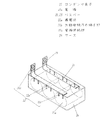
図1は本実施の形態のケースモールド型コンデンサの斜視図である。図1において、コンデンサ素子21は、ポリプロピレンなどの誘電体フィルムの片面または両面にアルミニウムなどの金属を蒸着させた金属化フィルム(図示せず)を一対とし、この金属化フィルムを誘電体フィルムを介して対向する状態で巻回し、その後小判形に偏平に形成され、コンデンサ素子21の両端面には亜鉛などを溶射して電極21aが形成される。
(Embodiment 1)
FIG. 1 is a perspective view of a case mold type capacitor according to the present embodiment. In FIG. 1, a
バスバー22は、長尺の導電体22aと、この導電体22aの長尺方向の端部に設けた外部接続用の端子部22bと、コンデンサ素子21の各電極21aに接続する電極接続部22cとを備える。バスバー22の電極接続部22cは、複数のコンデンサ素子21の各電極とそれぞれ接続されて並列接続する。外部接続用の端子部22bは、ケース24の開口部から表出するように配設される。
The
上記バスバー22の導電体22aは中空状の偏平管よりなる。この偏平管の内部を中空状にすることにより、高周波の大電流を流しても表皮効果により偏平管の肉厚全体に流れるので電流効率に優れる。
The
この偏平管22aの構成を図2に示す。この偏平管22aは、例えば銅管を圧潰したもの、或いは銅板を曲げ加工して円筒状に形成し、この円筒状を圧潰したもの等を用いることができる。中空状の厚みcは偏平管22aの肉厚bよりも薄くすることにより、ケースモールド型コンデンサの低背化を図ることができる。また、従来の金属板よりも偏平管の肉厚を薄くできるので、放熱効果が期待でき、材料コストも低減化を図ることができる。
The structure of the
外部接続用の端子部22bは、導電体22aの一方の端部を押し潰し、所定の長さaで折り曲げて2枚重ねにした構成にすることにより、外部から大電流を入力しても、端子部22bの発熱を抑制することができ、導電体22aに効率よく電流を流すことができる。
Even if a large current is input from the outside, the
電極接続部22cは、導電体22aの側部にコンデンサ素子21の電極ごとに銅等の板片を取り付けた構成よりなる。
The electrode connecting portion 22c has a configuration in which a plate piece such as copper is attached to each side of the
なお、バスバー23においても、バスバー22と同じ構成を有するもので、コンデンサ素子21のもう一方の電極に接続する。
The
ケース24は、充填樹脂(図示せず)を安定に保持するため、充填樹脂との親和性がよい材料であることが必要である。この要求に満足するものとしてポリフェニレンサルファイドが好ましい。また、放熱性を優先させる場合はアルミニウム等の金属ケースを用いることもできる。 The case 24 needs to be made of a material having good affinity with the filling resin in order to stably hold the filling resin (not shown). Polyphenylene sulfide is preferred as satisfying this requirement. Moreover, when giving priority to heat dissipation, metal cases, such as aluminum, can also be used.
充填樹脂は、熱硬化性のエポキシ樹脂などが用いられるが、急激な温度変化や冷熱サイクルに耐えるため、ケース24と充填樹脂の熱膨張係数を近づけて充填樹脂やケース24でのクラック発生を防止するため、無機フィラーを含有することが好ましい。無機フィラーはアルミナやシリカなどの無機物を主成分とするものでよく、また含有量は充填樹脂100重量部に対して30から80重量部程度が好ましい。 Thermosetting epoxy resin or the like is used as the filling resin. However, in order to withstand rapid temperature changes and cooling cycles, the thermal expansion coefficient of the case 24 and the filling resin are made close to prevent cracks in the filling resin and the case 24. Therefore, it is preferable to contain an inorganic filler. The inorganic filler may be mainly composed of an inorganic material such as alumina or silica, and the content is preferably about 30 to 80 parts by weight with respect to 100 parts by weight of the filled resin.
このように構成された本実施の形態1によるケースモールド型コンデンサは、バスバー22の導電体22aを中空状の偏平管にすることにより、従来の金属板を用いたときの表面積と同じにした場合、偏平管の肉厚を薄くしてバスバー22の断面積を小さくすることができるので、電流が効率良く流れ、放熱効果も優れることからバスバー22の温度が高くならず、ケースモールド型コンデンサの長寿命を向上させることができる。
In the case mold type capacitor according to the first embodiment configured as described above, when the
また、従来の金属板を用いたときの断面積と同じにした場合は、バスバー22に流す電流を大きくしても、導電体22aが中空状にしているので熱容量が小さく放熱効率も良いので、大電流用のケースモールド型コンデンサを提供することができる。
Also, if the cross-sectional area when using a conventional metal plate is the same, even if the current flowing through the
ここで、本実施の形態1のケースモールド型コンデンサと、比較例1として図3に示すバスバー32、33に金属板(銅板)を用いたときのケースモールド型コンデンサについて、バスバーの発熱温度と、寿命試験の結果を(表1)に示す。 Here, regarding the case mold type capacitor of the first embodiment and the case mold type capacitor when the metal plate (copper plate) is used for the bus bars 32 and 33 shown in FIG. The results of the life test are shown in (Table 1).
なお、本実施の形態1のバスバーは、銅管(φ13mm、肉厚0.4mm)をプレスして、図2に示す偏平管(a=20、b=1.0、c=0.2)を用いた。比較例1のバスバー32、33は、幅20mm、厚さ1.0mmのものを用いた。 The bus bar of the first embodiment is a flat tube (a = 20, b = 1.0, c = 0.2) shown in FIG. 2 by pressing a copper tube (φ13 mm, wall thickness 0.4 mm). Was used. The bus bars 32 and 33 of Comparative Example 1 were 20 mm wide and 1.0 mm thick.
寿命試験の条件は、温度100℃で、負荷電圧750V、リプル電流50Arms(周波数100kHz)を通電して、容量変化率が−5%に達した時間を算出し、比較例1を100としたときの指数を示す。 The conditions of the life test are as follows: when the temperature is 100 ° C., the load voltage is 750 V, the ripple current is 50 Arms (frequency: 100 kHz), the time when the capacity change rate reaches −5% is calculated, and the comparative example 1 is 100 The index of.
バスバーの発熱温度は、寿命試験を行ったときのバスバーの最も高い温度で、温度100℃から上昇した値である。 The exothermic temperature of the bus bar is the highest temperature of the bus bar when the life test is performed, and is a value increased from a temperature of 100 ° C.

(表1)から明らかなように、同外形寸法のバスバーにおいても印加されるリプル電流に伴い、実施の形態1では比較例1の約0.52倍の温度上昇に抑制することができるため、コンデンサ素子へのバスバーの温度上昇影響が少なくなることでコンデンサ寿命を1.45倍に長寿命化することが確認された。 As apparent from (Table 1), with the ripple current applied even in the bus bar having the same outer dimensions, in the first embodiment, the temperature rise can be suppressed to about 0.52 times that of Comparative Example 1, It was confirmed that the lifetime of the capacitor was extended 1.45 times by reducing the influence of the temperature rise of the bus bar on the capacitor element.
(実施の形態2)
図4は本実施の形態2のケースモールド型コンデンサの斜視図である。図4において、バスバー43、44は、導電体43a、44aと、外部接続用の端子部43b、44bと、電極接続部(番号付与せず)から構成されている。
(Embodiment 2)
FIG. 4 is a perspective view of the case mold type capacitor of the second embodiment. In FIG. 4, the bus bars 43 and 44 are made up of conductors 43a and 44a, external connection terminal portions 43b and 44b, and electrode connection portions (not numbered).
ここで、導電体43a、44aと電極接続部は上記実施の形態1と同様である。外部接続用の端子部43b、44bは円筒形に構成したものである。 Here, the conductors 43a and 44a and the electrode connecting portion are the same as those in the first embodiment. The terminal portions 43b and 44b for external connection are configured in a cylindrical shape.
このような外部接続用の端子部43b、44bにすることにより、外部側の接続部を棒状と簡単な構成にすることができる。また、接続方法も棒状を差し込んで圧着または溶接するといった簡単な方法で、接続の電流損失を低減することができ、バスバー43、44の発熱を低減することができる。 By using the terminal portions 43b and 44b for external connection as described above, the external connection portion can be formed into a simple bar shape. Further, the connection method is a simple method in which a rod-like shape is inserted and crimped or welded, so that the connection current loss can be reduced, and the heat generation of the bus bars 43 and 44 can be reduced.
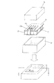
(実施の形態3)
図5は本実施の形態3のケースモールド型コンデンサの斜視図である。図5において、バスバーの導電体に貫通孔を数箇所開けたものを用いた以外は上記実施の形態1と同様である。
(Embodiment 3)
FIG. 5 is a perspective view of the case mold type capacitor of the third embodiment. In FIG. 5, the same as the first embodiment, except that the conductor of the bus bar has several through holes.
バスバー53、54には所定の間隔で貫通孔55を設けることにより、バスバー53、54を接続したコンデンサ素子をケースに挿入し、充填樹脂を注入したときに、導電体である偏平管の中空状に樹脂が充填するので、大電流を流しても偏平管内での接触がなく、絶縁性も保つことにより表皮効果が確保できるので、大電流用に適したケースモールド型コンデンサを提供することができる。
By providing through
本発明によるケースモールド型コンデンサは、複数のコンデンサを1つのケース内に収納して樹脂モールドする場合に、バスバーの電流効率に優れ、低コスト、小型軽量の設計を行うことができるので、特にハイブリッド自動車のモータ駆動用インバータ回路の平滑用等に有用である。 The case mold type capacitor according to the present invention is excellent in the current efficiency of the bus bar and can be designed at a low cost, a small size and a light weight when a plurality of capacitors are accommodated in one case and resin molded. This is useful for smoothing an inverter circuit for driving a motor of an automobile.
21 コンデンサ素子
21a 電極
22、23 バスバー
22a 導電体
22b 外部接続用の端子部
22c 電極接続部
24 ケース
21 Capacitor
Claims (3)
このコンデンサ素子の一対の電極に接続した一対のバスバーと、
コンデンサ素子を収容して樹脂モールドしたケースとを備えたケースモールド型コンデンサにおいて、
上記バスバーは、
樹脂モールドされた導電体と、
この導電体の端部に設けた外部接続用の端子部と、
導電体の側部から突出させてコンデンサ素子の電極に接続する電極接続部とを有し、
該導電体が、中空状かつ外部から中空部へ貫通する貫通孔を有し、かつ前記中空部には樹脂が充填した偏平管より構成されたことを特徴とするケースモールド型コンデンサ。 A capacitor element;
A pair of bus bars connected to a pair of electrodes of the capacitor element;
In a case mold type capacitor having a capacitor element and a resin molded case,
The bus bar is
A resin-molded conductor;
A terminal portion for external connection provided at the end of the conductor;
An electrode connecting portion that protrudes from the side of the conductor and connects to the electrode of the capacitor element
Conductive body, hollow and have a through hole penetrating from the outside into the hollow portion, and the case mold type capacitor, characterized in that the said hollow portion is configured from flat pipe resin is filled.
Priority Applications (1)
| Application Number | Priority Date | Filing Date | Title |
|---|---|---|---|
| JP2011089880A JP5945684B2 (en) | 2011-04-14 | 2011-04-14 | Case mold type capacitor |
Applications Claiming Priority (1)
| Application Number | Priority Date | Filing Date | Title |
|---|---|---|---|
| JP2011089880A JP5945684B2 (en) | 2011-04-14 | 2011-04-14 | Case mold type capacitor |
Publications (3)
| Publication Number | Publication Date |
|---|---|
| JP2012222313A JP2012222313A (en) | 2012-11-12 |
| JP2012222313A5 JP2012222313A5 (en) | 2014-05-29 |
| JP5945684B2 true JP5945684B2 (en) | 2016-07-05 |
Family
ID=47273471
Family Applications (1)
| Application Number | Title | Priority Date | Filing Date |
|---|---|---|---|
| JP2011089880A Active JP5945684B2 (en) | 2011-04-14 | 2011-04-14 | Case mold type capacitor |
Country Status (1)
| Country | Link |
|---|---|
| JP (1) | JP5945684B2 (en) |
Families Citing this family (3)
| Publication number | Priority date | Publication date | Assignee | Title |
|---|---|---|---|---|
| CN103680955B (en) * | 2013-12-21 | 2016-06-15 | 铜陵源丰电子有限责任公司 | A kind of thin film capacitor being easy to vertical and horizontal installation |
| CN104409622A (en) * | 2014-10-15 | 2015-03-11 | 中国计量学院 | Structure and manufacturing method of a high-frequency thin-film thermoelectric converter |
| JP6541845B1 (en) * | 2018-06-11 | 2019-07-10 | 三菱電機株式会社 | Capacitor for power converter and power converter using the same |
Family Cites Families (4)
| Publication number | Priority date | Publication date | Assignee | Title |
|---|---|---|---|---|
| JPH087777Y2 (en) * | 1989-08-14 | 1996-03-04 | 古河電気工業株式会社 | Electrical junction box |
| JP2004080972A (en) * | 2002-08-22 | 2004-03-11 | Toyota Motor Corp | Bus bar |
| JP2004104872A (en) * | 2002-09-06 | 2004-04-02 | Toyota Motor Corp | Connection structure of bus-bar |
| JP4985378B2 (en) * | 2007-12-17 | 2012-07-25 | パナソニック株式会社 | Case mold type capacitor |
-
2011
- 2011-04-14 JP JP2011089880A patent/JP5945684B2/en active Active
Also Published As
| Publication number | Publication date |
|---|---|
| JP2012222313A (en) | 2012-11-12 |
Similar Documents
| Publication | Publication Date | Title |
|---|---|---|
| WO2006109732A1 (en) | Metalized film capacitor, case module type capacitor using the same, inverter circuit, and vehicle drive motor drive circuit | |
| JP5796155B2 (en) | Case mold type capacitor | |
| JP2012199350A (en) | Case mold type capacitor | |
| WO2012098622A1 (en) | Case mold type capacitor | |
| JP2008288242A (en) | Case-molded capacitor | |
| JP5012140B2 (en) | Case mold type capacitor and inspection method thereof | |
| JP5012139B2 (en) | Case mold type capacitor | |
| US9793050B2 (en) | Capacitor and inverter | |
| JP6145691B2 (en) | Case mold type capacitor | |
| JP4985378B2 (en) | Case mold type capacitor | |
| JP5945684B2 (en) | Case mold type capacitor | |
| JP4967712B2 (en) | Case mold type capacitor | |
| JP2008130641A (en) | Case mold type capacitor | |
| JP2005108957A (en) | Case-mold film capacitor | |
| JP5978463B2 (en) | Metallized film capacitors | |
| JP5919489B2 (en) | Case mold type capacitor | |
| JP2006319300A (en) | Case molded capacitor | |
| JP2009194281A (en) | Case-molded capacitor | |
| JP5061693B2 (en) | Case mold type capacitor | |
| JP5906376B2 (en) | Case mold type capacitor | |
| JP2009200378A (en) | Composite metallized-film capacitor | |
| US11456117B2 (en) | Capacitor | |
| JP2009188158A (en) | Case molded capacitor | |
| JP5228581B2 (en) | Case mold type capacitor | |
| JP2007142454A (en) | Case-mold film capacitor |
Legal Events
| Date | Code | Title | Description |
|---|---|---|---|
| A521 | Request for written amendment filed |
Free format text: JAPANESE INTERMEDIATE CODE: A523 Effective date: 20140411 |
|
| A621 | Written request for application examination |
Free format text: JAPANESE INTERMEDIATE CODE: A621 Effective date: 20140411 |
|
| RD01 | Notification of change of attorney |
Free format text: JAPANESE INTERMEDIATE CODE: A7421 Effective date: 20140513 |
|
| A711 | Notification of change in applicant |
Free format text: JAPANESE INTERMEDIATE CODE: A711 Effective date: 20141007 |
|
| A977 | Report on retrieval |
Free format text: JAPANESE INTERMEDIATE CODE: A971007 Effective date: 20141225 |
|
| A131 | Notification of reasons for refusal |
Free format text: JAPANESE INTERMEDIATE CODE: A131 Effective date: 20150106 |
|
| A521 | Request for written amendment filed |
Free format text: JAPANESE INTERMEDIATE CODE: A523 Effective date: 20150303 |
|
| A131 | Notification of reasons for refusal |
Free format text: JAPANESE INTERMEDIATE CODE: A131 Effective date: 20150915 |
|
| A521 | Request for written amendment filed |
Free format text: JAPANESE INTERMEDIATE CODE: A523 Effective date: 20151026 |
|
| TRDD | Decision of grant or rejection written | ||
| A01 | Written decision to grant a patent or to grant a registration (utility model) |
Free format text: JAPANESE INTERMEDIATE CODE: A01 Effective date: 20160329 |
|
| A61 | First payment of annual fees (during grant procedure) |
Free format text: JAPANESE INTERMEDIATE CODE: A61 Effective date: 20160411 |
|
| R151 | Written notification of patent or utility model registration |
Ref document number: 5945684 Country of ref document: JP Free format text: JAPANESE INTERMEDIATE CODE: R151 |