JP5944708B2 - Rolling bearing - Google Patents
Rolling bearing Download PDFInfo
- Publication number
- JP5944708B2 JP5944708B2 JP2012064675A JP2012064675A JP5944708B2 JP 5944708 B2 JP5944708 B2 JP 5944708B2 JP 2012064675 A JP2012064675 A JP 2012064675A JP 2012064675 A JP2012064675 A JP 2012064675A JP 5944708 B2 JP5944708 B2 JP 5944708B2
- Authority
- JP
- Japan
- Prior art keywords
- seal ring
- seal
- bearing
- seal groove
- inner race
- Prior art date
- Legal status (The legal status is an assumption and is not a legal conclusion. Google has not performed a legal analysis and makes no representation as to the accuracy of the status listed.)
- Expired - Fee Related
Links
Images


Landscapes
- Rolling Contact Bearings (AREA)
- Sealing Of Bearings (AREA)
Description
この発明は、オイル潤滑される転がり軸受に係り、詳しくは、フィルタを通して流入するオイルで潤滑される転がり軸受に関するものである。 The present invention relates to a rolling bearing that is oil-lubricated, and more particularly to a rolling bearing that is lubricated with oil flowing through a filter.
自動車や各種建設用機械等のトランスミッションやディファレンシャル、減速機等の動力伝達機構や、あるいは、それらを備えた走行装置には転がり軸受が組み込まれている。
この種の装置では、転がり軸受が、動力伝達機構を潤滑するオイルと共通のオイルで潤滑される構造となっているものがある。
Rolling bearings are incorporated in transmissions such as automobiles and various construction machines, power transmission mechanisms such as differentials, reduction gears, and traveling devices including them.
In this type of apparatus, there is a structure in which the rolling bearing is lubricated with oil common to the oil that lubricates the power transmission mechanism.
しかし、トランスミッションやディファレンシャル、減速機等の動力伝達機構のケース内に収容されたオイルには、ギヤの摩耗粉(鉄粉等)等の異物が比較的多く含まれている。その異物が転がり軸受の内部に侵入すると、異物の噛み込みによって軌道面や転動面に剥離が生じて、転がり軸受の耐久性を低下させることになる。 However, oil contained in a case of a power transmission mechanism such as a transmission, a differential, and a speed reducer contains a relatively large amount of foreign matter such as gear wear powder (iron powder or the like). When the foreign matter enters the inside of the rolling bearing, the raceway surface and the rolling surface are peeled off due to the biting of the foreign matter, thereby reducing the durability of the rolling bearing.
このため、その異物の侵入を防止するため、転がり軸受に取付けるシールリングにフィルタを設けたフィルタ付き転がり軸受が提案されている。このフィルタ付き転がり軸受は、シールリングに設けたオイル流通用の通油孔に、異物を捕捉するためのフィルタを取付けたものである(例えば、特許文献1,2参照)。
For this reason, a rolling bearing with a filter in which a filter is provided in a seal ring attached to the rolling bearing has been proposed in order to prevent the entry of foreign matter. In this rolling bearing with a filter, a filter for capturing foreign matter is attached to an oil passage hole for oil circulation provided in a seal ring (see, for example,
上記特許文献1,2に記載されたフィルタ付き転がり軸受では、シールリングに設けた通油孔に対して、フィルタを接着剤や嵌め込み等により固定していると考えられる。フィルタを構成する極細いメッシュ部材を、相対的に厚いシールリングの成型と同時に同一の型枠で一体に樹脂等で形成することは困難だからである。
In the rolling bearing with a filter described in
このため、シールリングが熱膨張で変形することにより、フィルタの固定部分の一部がシールリングから外れたり、あるいは、フィルタがシールリングから完全に外れてしまう等、フィルタの脱落を生じさせることがある。 For this reason, deformation of the seal ring due to thermal expansion may cause the filter to fall off, such as a part of the fixed portion of the filter may be detached from the seal ring, or the filter may be completely detached from the seal ring. is there.
フィルタが脱落すると、そのままでは異物が転がり軸受の内部に侵入しやすくなるので、シールリングの交換が必要となる。シールリングの交換は、少なくとも動力伝達機構の分解を伴う作業となるので、いつでも容易にできるものではない。このため、フィルタは脱落しにくい構造であることが望ましい。 If the filter falls off, foreign matter easily rolls and enters the inside of the bearing, so that the seal ring needs to be replaced. Replacing the seal ring is an operation that involves at least the disassembly of the power transmission mechanism, and is not always easy. For this reason, it is desirable that the filter has a structure that does not easily drop off.
また、フィルタをより強固に固定できるように、予め製作されたフィルタをシールリングにインサート成型する手法が考えられる。フィルタをシールリングにインサート成型すれば、フィルタの外周部は、シールリングの素材である樹脂やゴムに埋め込まれた状態に保持される。このため、フィルタの脱落は生じにくくなる。 Also, a method of insert molding a prefabricated filter into a seal ring is conceivable so that the filter can be fixed more firmly. If the filter is insert-molded into the seal ring, the outer peripheral portion of the filter is held in a state of being embedded in resin or rubber that is a material of the seal ring. For this reason, the filter is less likely to drop off.
しかし、フィルタをシールリングにインサート成型しても、シールリングの熱膨張の度合いが大きくなると、フィルタがその熱膨張に追随できず、メッシュが破れたり穴が明くなどして損傷してしまうことがある。フィルタが損傷すると、異物は、その損傷箇所を通じて転がり軸受側に侵入するので、もはやシールリングは異物を捕捉する機能を発揮することができない。 However, even if the filter is insert-molded into the seal ring, if the degree of thermal expansion of the seal ring increases, the filter cannot follow the thermal expansion, and the mesh may be damaged or the holes may be damaged. There is. When the filter is damaged, foreign matter enters the rolling bearing side through the damaged portion, so that the seal ring can no longer function to capture the foreign matter.
また、シールリングの熱膨張の度合いが大きくなると、シールリングそのものが外径側へ膨らんで、内側軌道輪から完全に脱落してしまうこともある。このような状態になると、異物は、その脱落箇所の隙間を通じて転がり軸受側に侵入するので、同じく、もはやシールリングは異物を捕捉する機能を発揮することができない。 Further, when the degree of thermal expansion of the seal ring increases, the seal ring itself may swell to the outer diameter side and may completely fall off from the inner race. In such a state, foreign matter enters the rolling bearing side through the gap of the drop-off portion, and similarly, the seal ring can no longer function to capture the foreign matter.
そこで、この発明は、フィルタ付きのシールリングが熱膨張した際に、異物を捕捉する機能が維持できるようにすることを課題とする。 Accordingly, an object of the present invention is to maintain a function of capturing foreign matter when a seal ring with a filter is thermally expanded.
上記の課題を解決するため、この発明は、外側軌道輪と内側軌道輪との間に転動体を組み込み、前記外側軌道輪と前記内側軌道輪との間に形成された軸受空間の少なくとも一端の開口をシールリングで覆い、そのシールリングに形成された通油孔を覆うフィルタにより潤滑オイルに含まれる異物を捕捉するようになっており、前記シールリングは、少なくとも前記内側軌道輪に係止される係止部と、その係止部から外径側に向かって立ち上がる壁部とを備え、前記シールリングは前記係止部が前記内側軌道輪に設けた凹部に入り込むことによって前記内側軌道輪に対して熱膨張時に径方向へ移動可能に係止されている構成を採用した。 In order to solve the above problems, the present invention incorporates a rolling element between an outer race and an inner race, and at least one end of a bearing space formed between the outer race and the inner race. The opening is covered with a seal ring, and foreign matter contained in the lubricating oil is captured by a filter that covers the oil passage hole formed in the seal ring, and the seal ring is locked to at least the inner race. A locking portion and a wall portion rising from the locking portion toward the outer diameter side, and the seal ring enters the concave portion provided in the inner race by the engagement portion. On the other hand, a configuration is adopted in which it is locked so as to be movable in the radial direction during thermal expansion.
この構成によれば、シールリングは、係止部が内側軌道輪の凹部に入り込むことによって、その内側軌道輪に対して熱膨張時に径方向へ移動可能な状態で係止されている。このため、シールリングに想定される温度環境下で、常に、シールリングの内径側に設けた係止部が、内側軌道輪の凹部に入り込んだ状態に維持されるようにできる。すなわち、熱膨張後も、なお、シールリングと内側軌道輪との間に異物が入り込む隙間を生じさせない。したがって、シールリングが熱膨張した際に、異物を捕捉する機能を継続して発揮できる。 According to this configuration, the seal ring is locked in a state in which it can move in the radial direction during thermal expansion when the locking portion enters the recess of the inner track. For this reason, the locking portion provided on the inner diameter side of the seal ring can always be maintained in a state of entering the recess of the inner race ring under the temperature environment assumed for the seal ring. That is, even after thermal expansion, there is no gap between the seal ring and the inner race. Therefore, when the seal ring is thermally expanded, the function of capturing foreign matter can be continuously exhibited.
すなわち、転がり軸受内のシールリングの使用環境下において、オイル等の温度上昇とともに、そのシールリングは主に外径側に向かって熱膨張する。そして、使用環境下で想定される最高の温度、すなわち、最大の熱膨張量となった状態のシールリングが、その膨張状態でもなお、内側軌道輪との間に有害な異物が入り込む隙間が生じていないことが求められる。シールリングに想定される温度環境下では、常に、係止部が凹部に入り込んだ状態が維持されるので、熱膨張後もなお、内側軌道輪との間に有害な異物が入り込む隙間が生じない。 That is, under the usage environment of the seal ring in the rolling bearing, the seal ring mainly thermally expands toward the outer diameter side as the temperature of the oil or the like rises. The seal ring in the state where the maximum temperature expected under the usage environment, that is, the maximum amount of thermal expansion, is still in the expanded state, and there is still a gap for harmful foreign objects to enter between the inner ring and the inner ring. Not required. Under the temperature environment assumed for the seal ring, the state in which the engaging portion is always in the recess is maintained, so that there is no gap between the inner race and the harmful foreign matter even after thermal expansion. .
この構成において、係止部は、内側軌道輪の凹部に入り込んで係止されることで、そのシールリングと内側軌道輪との間から有害な異物が入り込まないようになっていればよく、その凹部は、例えば、内側軌道輪の端面であっても外径面であってもよい。 In this configuration, the locking portion may enter and be recessed into the inner race, so that harmful foreign substances do not enter between the seal ring and the inner race, The recess may be, for example, an end surface of the inner race or an outer diameter surface.
また、前記凹部は前記内側軌道輪に形成された周方向のシール溝であり、前記係止部は前記シール溝に入り込む突出部を備える構成を採用することができる。
すなわち、係止部を構成する突出部は、壁部の内径側端部に設けることができる。突出部がシール溝に入り込むことにより、シールリングは前記内側軌道輪に対して熱膨張時に径方向へ移動可能に係止されている構成である。
Moreover, the said recessed part is the circumferential seal groove formed in the said inner race, and the latching part can employ | adopt the structure provided with the protrusion part which penetrates into the said seal groove.
That is, the protrusion part which comprises a latching | locking part can be provided in the inner diameter side edge part of a wall part. When the protruding portion enters the seal groove, the seal ring is locked to the inner race so as to be movable in the radial direction during thermal expansion.
なお、互いに係止する係止部と凹部とは、周方向に沿って断続的に配置されていてもよいし、全周に亘って連続的であってもよい。 In addition, the latching | locking part and recessed part which mutually latch may be arrange | positioned intermittently along the circumferential direction, and may be continuous over the perimeter.
また、このシールリングを取付ける転がり軸受の種別は自由であり、例えば、転動体として円すいころを用いた円すいころ軸受であってもよいし、その他、転動体としてボールを用いた深溝玉軸受や、円筒ころを用いた円筒ころ軸受、あるいは、球面ころを用いた自動調心ころ軸受等であってもよい。 In addition, the type of rolling bearing to which this seal ring is attached is free, for example, a tapered roller bearing using a tapered roller as a rolling element, a deep groove ball bearing using a ball as a rolling element, A cylindrical roller bearing using cylindrical rollers, or a self-aligning roller bearing using spherical rollers may be used.
転がり軸受が円すいころ軸受である場合には、前記シール溝は、前記内側軌道輪の大つば外径面に開口して形成されている構成とすることができる。また、転がり軸受が深溝玉軸受、円筒ころ軸受、又は、自動調心ころ軸受である場合には、前記シール溝は、その転がり軸受の前記内側軌道輪の端部外径面に開口して形成されている構成とすることができる。 In the case where the rolling bearing is a tapered roller bearing, the seal groove may be formed so as to open to the outer diameter surface of the inner collar of the inner race. Further, when the rolling bearing is a deep groove ball bearing, a cylindrical roller bearing, or a self-aligning roller bearing, the seal groove is formed to open on the outer diameter surface of the end of the inner race of the rolling bearing. It can be set as the structure currently made.
また、前記係止部として突出部を備えた構成において、前記突出部は、前記転動体に近い側の内側突出部と遠い側の外側突出部とを備え、前記シール溝は、前記内側突出部が入り込む内側シール溝と、前記外側突出部が入り込む外側シール溝とを備えた構成を採用することができる。
この構成によれば、シールシングの係止部は、軸方向に沿って二つの突出部を備えるので、その軸方向位置の異なる二つの突出部によって、シールリングをより確実に内側軌道輪に係止できる。
Further, in the configuration provided with a protruding portion as the locking portion, the protruding portion includes an inner protruding portion on the side close to the rolling element and an outer protruding portion on the far side, and the seal groove includes the inner protruding portion. It is possible to adopt a configuration including an inner seal groove into which the outer protrusion enters and an outer seal groove into which the outer protrusion enters.
According to this configuration, since the locking portion of the sealing single includes the two protruding portions along the axial direction, the sealing ring is more securely engaged with the inner race by the two protruding portions having different axial positions. You can stop.
また、その内側突出部が前記内側シール溝に入り込む深さは、前記外側突出部が前記外側シール溝に入り込む深さよりも浅く設定されている構成を採用することができる。
この構成によれば、シールリングを軸受空間の開口に押し込んで固定する際に、より奥側に位置する内側突出部を弾性変形又は加熱変形させ、容易にシール溝に嵌め込みできる。また、手前側に位置する外側突出部のシール溝に対する入り込み深さは深いので、大きな外径方向への熱膨張に対しても、シールリングと内側軌道輪との係止を維持できる。
Further, the depth at which the inner protrusion enters the inner seal groove can be configured to be shallower than the depth at which the outer protrusion enters the outer seal groove.
According to this configuration, when the seal ring is pushed into the opening of the bearing space and fixed, the inner projecting portion located on the deeper side can be elastically deformed or heat deformed, and can be easily fitted into the seal groove. Moreover, since the penetration depth of the outer protrusion located on the near side with respect to the seal groove is deep, the engagement between the seal ring and the inner race can be maintained even with respect to thermal expansion in a large outer diameter direction.
なお、前記内側突出部と前記外側突出部とは、それぞれ周方向全周に亘って連続的に設けてもよいし、それぞれ、周方向に沿って断続的に設けてもよい。すなわち、前記内側突出部を周方向に沿って断続的に、前記外側突出部を周方向に沿って連続的としてもよい。あるいは、前記内側突出部を周方向に沿って連続的に、前記外側突出部を周方向に沿って断続的としてもよい。また、その両方を連続的又は断続的とすることもできる。
また、前記内側突出部と前記外側突出部とを周方向に沿って交互配置とすることもできる。内側突出部と外側突出部とが周方向に交互配置であれば、シールリングを軸受空間の開口に押し込んで固定する際に、内側突出部が外側突出部の死角に入りにくい。このため、奥側の内側突出部がシール溝に嵌まっていることを目視で確認しやすい。
In addition, the said inner side protrusion part and the said outer side protrusion part may each be provided continuously over the perimeter of a circumferential direction, respectively, and may each be provided intermittently along the circumferential direction. That is, the inner protrusion may be intermittent along the circumferential direction and the outer protrusion may be continuous along the circumferential direction. Alternatively, the inner protrusion may be continuous along the circumferential direction, and the outer protrusion may be intermittent along the circumferential direction. Both can be continuous or intermittent.
Further, the inner protrusions and the outer protrusions can be arranged alternately along the circumferential direction. If the inner protrusions and the outer protrusions are alternately arranged in the circumferential direction, the inner protrusion is less likely to enter the blind spot of the outer protrusion when the seal ring is pushed into the bearing space and fixed. For this reason, it is easy to visually confirm that the inner projecting portion on the back side is fitted in the seal groove.
この内側突出部と外側突出部とを備えた構成において、少なくとも前記外側突出部は、前記外側シール溝内において軸方向へ移動可能である構成を採用することができる。外側突出部が外側シール溝内で軸方向へ移動可能であれば、シールリングが熱膨張する際に、外側突出部がそのシール溝内で円滑に径方向へ移動できる。このため、外側突出部がシール溝内で拘束されず、そのシールリングに熱膨張に伴う外径方向への引っ張り力が作用することを防止し、フィルタの損傷を回避し得る。 In the configuration including the inner protruding portion and the outer protruding portion, it is possible to adopt a configuration in which at least the outer protruding portion is movable in the axial direction within the outer seal groove. If the outer protrusion is movable in the axial direction in the outer seal groove, the outer protrusion can smoothly move in the radial direction in the seal groove when the seal ring is thermally expanded. For this reason, the outer protrusion is not restrained in the seal groove, and it is possible to prevent the pulling force in the outer diameter direction due to thermal expansion from acting on the seal ring, and to avoid damage to the filter.
これらの構成において、前記突出部に軸方向へ突出する係止凸部を設け、前記シール溝内に係止凹部を設け、前記係止凸部が前記係止凹部に入り込むことで、前記シールリングは、その半径方向又は周方向への動き、あるいは、その両方向への動きが規制される構成を採用することができる。 In these configurations, a locking projection that protrudes in the axial direction is provided on the protruding portion, a locking recess is provided in the seal groove, and the locking projection enters the locking recess, whereby the seal ring Can adopt a configuration in which movement in the radial direction or circumferential direction, or movement in both directions thereof is restricted.
この構成によれば、シールリングが熱膨張した際、その熱膨張したシールリングの径方向への所定量以上の移動(特に、冷間状態から外径方向への膨張による移動)を規制しつつ、同時に、シールリングが内側軌道輪に対して周方向に回転することを防止することができる。 According to this configuration, when the seal ring is thermally expanded, the movement of the thermally expanded seal ring by a predetermined amount or more in the radial direction (particularly, movement due to expansion from the cold state to the outer diameter direction) is regulated. At the same time, the seal ring can be prevented from rotating in the circumferential direction with respect to the inner race.
これらの構成において、前記外側シール溝は、前記内側軌道輪の端面に開口して形成されている構成を採用することができる。シール溝への入り込み深さが深い外側突出部は、そのシール溝への嵌め込みが容易でない場合(外側突出部がシール溝内で折れ曲がってしまうような状態)も想定されるが、この構成のように、外側シール溝を内側軌道輪の端面に開口させれば、その嵌め込みは容易である。 In these configurations, it is possible to adopt a configuration in which the outer seal groove is formed to be open at an end surface of the inner race. The outer projecting part having a deep penetration depth into the seal groove is assumed to be difficult to fit into the seal groove (a state in which the outer projecting part is bent in the seal groove). In addition, if the outer seal groove is opened on the end face of the inner race, the fitting is easy.
このとき、前記内側軌道輪の端面に、その内側軌道輪の内径に嵌め合いで固定される軸肩が当接するようにし、前記外側シール溝の前記端面の開口は、前記軸肩によって塞がれる構成を採用することができる。この構成によれば、外側突出部は外側シール溝内に確実に保持されるようになる。すなわち、外側突出部を外側シール溝へ嵌め込んだ後、軸肩で外側シール溝の端面の開口を塞ぐことができる。 At this time, the end surface of the inner raceway is brought into contact with a shaft shoulder fitted and fixed to the inner diameter of the inner raceway, and the opening of the end surface of the outer seal groove is closed by the shaft shoulder. A configuration can be employed. According to this configuration, the outer protrusion is securely held in the outer seal groove. That is, after the outer protrusion is fitted into the outer seal groove, the opening on the end surface of the outer seal groove can be closed with the shaft shoulder.
また、他の手段として、この発明は、外側軌道輪と内側軌道輪との間に転動体を組み込み、前記外側軌道輪と前記内側軌道輪との間に形成された軸受空間の少なくとも一端の開口をシールリングで覆い、そのシールリングに形成された通油孔を覆うフィルタにより潤滑オイルに含まれる異物を捕捉するようにし、前記シールリングは樹脂で構成され、前記フィルタと前記シールリングとはインサート成型により一体であり、前記フィルタの素材は、前記シールリングと同一の素材であるか、ほぼ同じ線膨張係数の素材、又は、前記シールリングの線膨張係数以上の線膨張係数を有する素材である構成を採用した。 According to another aspect of the present invention, a rolling element is incorporated between the outer race and the inner race, and an opening at least one end of a bearing space formed between the outer race and the inner race is provided. The filter is covered with a seal ring, and foreign matter contained in the lubricating oil is captured by a filter that covers the oil passage hole formed in the seal ring. The seal ring is made of resin, and the filter and the seal ring are inserts. The filter is integrated, and the material of the filter is the same material as the seal ring, a material having substantially the same linear expansion coefficient, or a material having a linear expansion coefficient equal to or greater than the linear expansion coefficient of the seal ring. Adopted the configuration.
フィルタとシールリングとを同一の素材、ほぼ同じ線膨張係数の素材、又は、そのフィルタを、前記シールリングの線膨張係数以上の線膨張係数を有する素材としたことから、シールリングが熱膨張しても、フィルタがそのシールリングの熱膨張に追随して同程度膨張するか、あるいは、フィルタがシールリングの膨張量よりも大きく膨張する。このため、フィルタのメッシュが破れたり穴が明くなどの損傷を生じさせない。 Since the filter and the seal ring are made of the same material, a material having substantially the same linear expansion coefficient, or the filter is made of a material having a linear expansion coefficient equal to or greater than that of the seal ring, the seal ring is thermally expanded. However, the filter expands to the same extent following the thermal expansion of the seal ring, or the filter expands larger than the expansion amount of the seal ring. For this reason, it does not cause damage such as a broken mesh or a hole in the filter.
なお、そのフィルタやシールリングの素材として、例えば、ポリアミド樹脂を採用することができる。また、フィルタとシールリングとが異なる素材である場合、それらの素材同士は、想定される温度環境での熱膨張の際に、フィルタに損傷を生じさせない程度に近似したほぼ同じ線膨張係数の素材であることが必要である。このとき、その素材同士は、同一の線膨張係数の材料であればさらに好ましい。 As a material for the filter and seal ring, for example, a polyamide resin can be employed. In addition, when the filter and seal ring are different materials, they are materials of approximately the same linear expansion coefficient that are approximate to the extent that they do not cause damage to the filter during thermal expansion in the assumed temperature environment. It is necessary to be. At this time, it is more preferable that the materials are materials having the same linear expansion coefficient.
このフィルタとシールリングとをインサート成型により一体とし、且つ、そのフィルタとシールリングとは同一の素材、ほぼ同じ線膨張係数の素材、又は、そのフィルタは前記シールリングの線膨張係数以上の線膨張係数を有する素材とした構成において、シールリングの軌道輪に対する係止構造、係止方法は、種々の構成を採用することができる。また、シールリングの軌道輪に対する係止構造、係止方法として、前述のシールリングの係止部及び内側軌道輪の凹部に係る各構成を採用することもできる。 The filter and the seal ring are integrated by insert molding, and the filter and the seal ring are made of the same material, substantially the same linear expansion coefficient, or the filter has a linear expansion larger than the linear expansion coefficient of the seal ring. In the structure made of a material having a coefficient, various structures can be adopted as the locking structure and locking method of the seal ring with respect to the raceway. Further, as the locking structure and locking method of the seal ring with respect to the raceway, it is possible to adopt the respective configurations relating to the seal ring latching portion and the inner raceway recess.
すなわち、前記係止部は、前記壁部の内径側端部に設けられた突出部を備え、前記凹部は、前記内側軌道輪に形成された周方向のシール溝であり、その突出部が前記シール溝に入り込むことにより、前記シールリングは前記内側軌道輪に対して熱膨張時に径方向へ移動可能に係止されている構成を採用することができる。 That is, the locking portion includes a protruding portion provided at an inner diameter side end of the wall portion, and the concave portion is a circumferential seal groove formed in the inner race, and the protruding portion is the By entering the seal groove, it is possible to adopt a configuration in which the seal ring is locked to the inner race ring so as to be movable in the radial direction during thermal expansion.
また、前記シールリングの外側の端部に、外側軌道輪に当接する、又は、隙間をもって対向するリップ部を備えた構成を採用することができる。リップ部は、シールリングと別体に成型して、両者を接着、嵌合等により固定することができる。シールリングとリップ部とが別体であれば、例えば、シールリングにはガラス繊維強化樹脂等の比較的変形しにくい素材を、また、リップ部にはゴム等、シールリングよりも柔らかい素材を採用することができる。 Moreover, the structure provided with the lip | rip part which contact | abuts to an outer track | orbit ring, or opposes with a clearance gap can be employ | adopted for the outer edge part of the said seal ring. The lip portion can be molded separately from the seal ring and can be fixed by bonding, fitting or the like. If the seal ring and the lip are separate, for example, a material that is relatively difficult to deform, such as glass fiber reinforced resin, is used for the seal ring, and a material that is softer than the seal ring, such as rubber, is used for the lip. can do.
また、前記シールリングは、前記壁部から伸びて前記外側軌道輪に微小間隙をおいて対向するラビリンスシール形成部を備えた構成とすることもできる。前記ラビリンスシール形成部は、前記壁部から軸方向に伸びる円環部材であり、その円環部材の先端が前記外側軌道輪の端面に微小間隙をおいて対向し、その外径面が前記外側軌道輪を保持するハウジングに微小間隙をおいて対向する構成とできる。ラビリンスシール形成部は、シールリングと一体に成型することもできるし、シールリングと別体に成型して、両者を接着、嵌合等により固定してもよい。 The seal ring may include a labyrinth seal forming portion that extends from the wall portion and faces the outer raceway with a minute gap. The labyrinth seal forming portion is an annular member extending in the axial direction from the wall portion, the tip of the annular member is opposed to the end surface of the outer raceway with a minute gap, and the outer diameter surface thereof is the outer surface. It can be configured to face the housing holding the raceway with a minute gap. The labyrinth seal forming portion may be molded integrally with the seal ring, or may be molded separately from the seal ring and fixed by bonding, fitting or the like.
この構成では、シールリングは、外径側に、外側軌道輪に微小間隙をおいて対向するラビリンスシール形成部を備えているから、そのラビリンスシールを通じたオイルの流通は許容される。且つ、その間隙は微小であるから、転がり軸受側への有害な異物の侵入は阻止されている。また、シールリングの熱膨張によって、そのラビリンスシールの微小間隙が狭くなったり、あるいは閉じたりすることは差し支えない。 In this configuration, since the seal ring includes the labyrinth seal forming portion facing the outer race on the outer diameter side with a minute gap, oil circulation through the labyrinth seal is allowed. In addition, since the gap is very small, entry of harmful foreign substances into the rolling bearing side is prevented. Also, the labyrinth seal micro-gap may be narrowed or closed due to thermal expansion of the seal ring.
このラビリンスシール形成部は、外側軌道輪に微小間隙をおいて対向していればよく、そのラビリンスシールは、シールリングのラビリンスシール形成部と、外側軌道輪の端面、内径面、あるいは、その外側軌道輪を保持する回転ハウジングの内径面との間に形成されている構成が考えられる。 The labyrinth seal forming portion only needs to be opposed to the outer raceway with a minute gap, and the labyrinth seal is composed of the labyrinth seal formation portion of the seal ring, the end face of the outer raceway, the inner surface, The structure currently formed between the internal diameter surfaces of the rotation housing holding a bearing ring can be considered.
例えば、ラビリンスシール形成部が、前記壁部から軸方向に伸びる円環部材であり、その円環部材の先端が前記外側軌道輪の端面に微小間隙をおいて対向し、その外径面が前記外側軌道輪を保持するハウジングに微小間隙をおいて対向する構成とすることができる。
この構成では、円筒状を成すラビリンスシール形成部の外径面が、外側軌道輪を保持する回転ハウジングに微小間隙をおいて対向し、ラビリンスシール形成部の先端が外側軌道輪の端面に微小間隙をおいて対向する。このため、シールリングの熱膨張の際に、その回転ハウジング側の微小間隙を縮小する方向(外径方向)への熱膨張が許容されやすい。このようなラビリンスシール構造を備えたシールリングでは、従来、熱膨張による脱落が生じやすかったので、本構造とする効果がより高い。なお、このラビリンスシール形成部を構成する円環部材は、例えば、円筒部材であってもよいし、外面又は内面にテーパ面を有する部材であってもよい。
For example, the labyrinth seal forming portion is an annular member extending in the axial direction from the wall portion, the tip of the annular member faces the end surface of the outer race ring with a minute gap, and the outer diameter surface thereof is It can be set as the structure which opposes the housing which hold | maintains an outer race ring with a micro gap.
In this configuration, the outer diameter surface of the cylindrical labyrinth seal forming portion faces the rotating housing that holds the outer raceway with a small gap, and the tip of the labyrinth seal formation portion has a minute gap on the end surface of the outer raceway ring. Oppose. For this reason, during the thermal expansion of the seal ring, thermal expansion in the direction of reducing the minute gap on the rotating housing side (outer diameter direction) is likely to be allowed. In the seal ring provided with such a labyrinth seal structure, the drop-off due to thermal expansion has been easy to occur conventionally, so that the effect of this structure is higher. In addition, the circular member which comprises this labyrinth seal formation part may be a cylindrical member, for example, and may be a member which has a taper surface on an outer surface or an inner surface.
この発明は、シールリングに想定される温度環境下で、常に、シールリングの内径側に設けた係止部が、内側軌道輪の凹部に入り込んだ状態に維持されるようにしたので、熱膨張後もなお、シールリングと内側軌道輪との間に有害な異物が入り込む隙間を生じさせない。このため、シールリングが熱膨張した際に、異物を捕捉する機能を継続して発揮できる。 In this invention, under the temperature environment assumed for the seal ring, the locking portion provided on the inner diameter side of the seal ring is always maintained in a state where it enters the concave portion of the inner race ring. Even after that, no gap is formed between the seal ring and the inner raceway, in which harmful foreign substances enter. For this reason, when the seal ring is thermally expanded, the function of capturing foreign matter can be continuously exhibited.
また、この発明は、フィルタとシールリングとを同一の素材、ほぼ同じ線膨張係数の素材、又は、そのフィルタを、前記シールリングの線膨張係数以上の線膨張係数を有する素材としたことから、シールリングが熱膨張しても、フィルタのメッシュが破れたり穴が明くなどの損傷を生じさせない。このため、シールリングが熱膨張した際に、異物を捕捉する機能を継続して発揮できる。 Further, in the present invention, the filter and the seal ring are made of the same material, a material having substantially the same linear expansion coefficient, or the filter is made of a material having a linear expansion coefficient equal to or higher than the linear expansion coefficient of the seal ring. Even if the seal ring is thermally expanded, it does not cause damage such as tearing of the filter mesh or perforation. For this reason, when the seal ring is thermally expanded, the function of capturing foreign matter can be continuously exhibited.
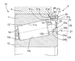
以下、この発明の実施形態を図面に基づいて説明する。図1は、この発明に係る転がり軸受10の要部拡大断面図を示す。
Embodiments of the present invention will be described below with reference to the drawings. FIG. 1 shows an enlarged cross-sectional view of a main part of a rolling
この転がり軸受10は、図13に示す鉱山用ダンプトラック(建設用機械)1の走行装置4に、動力伝達機構Tとともに組み込まれるものである。鉱山用ダンプトラック1は、荷台と運転台を支えるシャーシ2が、複数の駆動輪(タイヤ)3によって支持されている。走行装置4は、この駆動輪3に動力を伝達する。
This rolling
走行装置4の構成は、図12に示すように、駆動源である走行モータ5と、この走行モータ5の回転軸に接続されるシャフト6を備える。そのシャフト6の先端部の外側には、動力伝達機構Tとして減速機が配置されている。
また、シャフト6の外側には、固定の車軸を形成するスピンドル7が配置されている。このスピンドル7の外側には、その転がり軸受10を介してホイール9が配置されている。ホイール9の回転は、リム8を介して駆動輪3に伝達される。
As shown in FIG. 12, the configuration of the traveling
Further, a
この走行装置4では、減速機として遊星歯車機構50を採用している。遊星歯車機構50は、第一遊星歯車機構50aと第二遊星歯車機構50bとを備え、この2つの遊星歯車機構50a,50bを介して、シャフト6の回転を減速してホイール9に伝達する。ただし、減速機の構成はこの例に限定されず、他の構成からなる遊星歯車機構を用いた減速機構や、あるいは、遊星歯車機構以外の周知の減速機構を採用することができる。
In this traveling
この走行装置4では、スピンドル7とホイール9との間の転がり軸受10として、複列の円すいころ軸受を採用している。この複列の円すいころ軸受を介して駆動輪3を車軸に支持している。この種の建設用機械では、大きなラジアル荷重に耐え得る構造とするため、転がり軸受10として円すいころ軸受が用いられることが多い。
In this traveling
転がり軸受10の構成は、図12に示すように、外側軌道輪11と内側軌道輪12の各軌道面11a,12aの間に、転動体13として円すいころが組み込まれている。転動体13は、保持器14によって周方向に保持されている。
In the configuration of the rolling
並列する転がり軸受10は、円すいころの小径側端面同士が背面合わせになるように配置されている。すなわち、内側軌道輪12の軌道面12aと外側軌道輪11の軌道面11aとは、2列の転がり軸受10,10の軸方向外側から、その2列の転がり軸受10,10間の中央部へ向かう側に向かって互いの距離が狭まるように設けられている。
The
また、その距離が狭まる方向へ向かって外側軌道輪11に対して内側軌道輪12を押圧することにより、各転動体13に予圧が付与されている。この予圧は、図12に示す軸受押え部品17を、スピンドル7に対してボルト17aで締め付けることにより、両内側軌道輪12,12に対して、対側の軸受押え部品18との間で軸方向に圧縮力を作用させることで付与することができる。
Moreover, the preload is given to each rolling
この動力伝達機構Tと転がり軸受10とは、共通の潤滑用のオイルで潤滑されるようになっている。すなわち、走行装置4のケーシング内には一定のレベルまでオイルが貯留されているので、動力伝達機構Tや転がり軸受10の少なくとも下部は、そのオイルに浸かった状態である。これにより、動力伝達機構Tや転がり軸受10の構成部品が、潤滑されるようになっている。
The power transmission mechanism T and the rolling
なお、内側軌道輪12は、非回転軸である車軸(前記スピンドル7)に装着され回転不能である。また、外側軌道輪11は、回転ハウジングHと一体に回転するように装着される。回転ハウジングHは、駆動輪3の前記ホイール9と一体の部材として形成されるか、あるいは、前記ホイール9と一体に回転可能に結合される。
The
また、ケーシング内において、転がり軸受10の動力伝達機構Tに近い側に、その動力伝達機構T側から転がり軸受10側へのオイルの流通路を備える。すなわち、動力伝達機構Tと転がり軸受10とは共通のオイルで潤滑されるから、その動力伝達機構Tと転がり軸受10との間が、相互間のオイルの流通路となっている。
この実施形態では、転がり軸受10は軸方向に並列して2つ設けられているので、オイルの流通路は、動力伝達機構Tに近い側の転がり軸受10の動力伝達機構T側の開口、すなわち、外側軌道輪11と内側軌道輪12との間に形成された軸受空間の動力伝達機構T側の開口である。図1及び図2は、この動力伝達機構Tに近い側の転がり軸受10の要部を示し、いずれも、図中左側がその動力伝達機構T側の開口である。
Further, in the casing, an oil flow path from the power transmission mechanism T side to the rolling
In this embodiment, since the two rolling
この動力伝達機構T側の転がり軸受10に、シール部材Sが取付けられる。シール部材Sは、図12に示すように、動力伝達機構T側の転がり軸受10の軸受空間における動力伝達機構T側の開口を覆うように取付けられる。
なお、必要であれば、動力伝達機構Tから遠い側の転がり軸受10においても、その動力伝達機構Tの反対側の開口に、同様なシール部材Sを取付けてもよい。
A seal member S is attached to the rolling
If necessary, a similar seal member S may be attached to the opening on the opposite side of the power transmission mechanism T in the rolling
シール部材Sの構成は、図1に示すように、転がり軸受10の内側軌道輪12に係止される係止部21と、その係止部21から外径側に向かって立ち上がる壁部25と、その壁部から伸びるラビリンスシール形成部26とを有する断面L字状のシールリング20(シールリングの本体)を備える。
As shown in FIG. 1, the seal member S includes a locking
シールリング20は樹脂で構成され、そのシールリング20の壁部25に形成された通油孔22を覆うように、同一の樹脂からなるフィルタ23がインサート成型により一体とされたものである。
フィルタ23は、通油孔22の長さ方向(シールリング20の厚さ方向)のほぼ中央部に位置する。そのフィルタ23の周縁部が、通油孔22の周囲においてシールリング20の樹脂に埋め込まれて固定されている。
The
The
フィルタ23の素材とシールリング20の素材とを同一の樹脂素材としたことから、フィルタ23の素材とシールリング20の素材とは同一の熱膨張率である。このため、転がり軸受10内の潤滑用のオイルの温度上昇により、シールリング20が熱膨張しても、フィルタ23がそのシールリング20の熱膨張に追随して同程度膨張する。したがって、フィルタ23のメッシュが破れたり穴が明くなどの損傷を生じさせない。
Since the material of the
なお、このフィルタ23やシールリング20の素材としては、この実施形態では、ポリアミド樹脂等を採用しているが、他の樹脂を採用してもよい。他の樹脂としては、例えば、ポリアセタール(POM)、ポリカーボネート(PC)、ポリエチレンテレフタレート(PET)、ポリブチレンテレフタレート(PBT)、ポリエーテルエーテルケトン(PEEK)、ポリフェニレンスルファイド(PPS)、ポリテトラフロロエチレン(PTFE)、ポリスルホン(PSF)、ポリエーテルサルフォン(PES)、ポリイミド(PI)、ポリエーテルイミド(PEI)などがある。また、それらの樹脂を用いたガラス繊維強化樹脂としてもよい。ガラス繊維強化樹脂としては、例えば、PA(ポリアミド)46+GF、あるいは、PA(ポリアミド)66+GFといったものを採用できる。
In this embodiment, a polyamide resin or the like is used as a material for the
ガラス繊維の配合割合は、樹脂の収縮率と必要強度から最適化され、例えば、15〜35%、より好ましくは25〜30%とすることが望ましい。一般に、ガラス繊維配合割合が多いと、収縮率は小さくなり、成型後の寸法管理が容易になる。逆に、ガラス繊維配合割合が小さいと、樹脂の強度が低下し、変形しやすくなるため、収縮率と強度のバランスが最適な配合割合は25〜30%である。
また、これらのフィルタ23やシールリング20の素材として、ガラス繊維強化樹脂の他、炭素繊維強化樹脂やポリエチレン繊維強化樹脂、又は、アラミド繊維強化樹脂等でも適用できる。
The blending ratio of the glass fiber is optimized from the shrinkage ratio of the resin and the required strength, and is, for example, 15 to 35%, more preferably 25 to 30%. In general, when the glass fiber blending ratio is large, the shrinkage rate becomes small, and dimensional management after molding becomes easy. On the contrary, if the glass fiber blending ratio is small, the strength of the resin is lowered and the resin is easily deformed. Therefore, the optimal blending ratio between the shrinkage rate and the strength is 25 to 30%.
In addition to glass fiber reinforced resin, carbon fiber reinforced resin, polyethylene fiber reinforced resin, aramid fiber reinforced resin, or the like can be used as a material for these
なお、この実施形態では、フィルタ23とシールリング20とを同一の素材とし、それらをインサート成型により一体としているが、フィルタ23の素材は、シールリング20と同一の素材には限定されず、そのシールリング20の素材とほぼ同じ線膨張係数の素材や、シールリング20の線膨張係数以上の線膨張係数を有する素材としてもよい。
このような構成においても、フィルタ23は、シールリング20の熱膨張に追随して同程度膨張するか、あるいは、フィルタ23がシールリング20の膨張量よりも大きく膨張するので、フィルタ23が過度に引張られることがなく、その損傷を防止できる。
In this embodiment, the
Even in such a configuration, the
また、シールリング20の熱膨張時におけるフィルタの損傷を危惧する必要がない場合には、線膨張係数の数値に関係なく、フィルタ23とシールリング20とに任意の素材を採用することができる。
In addition, when there is no need to worry about damage to the filter during thermal expansion of the
なお、この実施形態の通油孔22は、図3に示すように、側面視長方形状の長孔を成す。この通油孔22が、シールリング20の周方向に沿って間隔をおいて複数設けられている。通油孔22の形状や数、配置間隔は適宜設定することができる。なお、通油孔22の形状は、側面視長方形状の長孔以外の形状であってもよく、例えば、側面視円弧状の長孔等であってもよい。
In addition, as shown in FIG. 3, the
フィルタ23の構成としては、メッシュサイズが0.1〜1mm程度の網目状の樹脂を採用し得る。ここでは、メッシュサイズが0.5mmの網目状の樹脂を採用しているが、フィルタ23のメッシュサイズは、捕捉しようとする異物の径に応じて適宜設定することができる。なお、軸受寿命を長く確保し得る最適なメッシュサイズについては後述する。
As a configuration of the
シールリング20は、その内径側に設けた係止部21が、内側軌道輪12に設けた周方向のシール溝(凹部)30に入り込むことによって、その熱膨張の際に、内側軌道輪12に対して径方向へ移動可能となるように係止されている。
When the locking
また、ラビリンスシール形成部26は、壁部25の外径側端縁から軸方向内側に伸びる円筒部材であり、その円筒部材の先端が、外側軌道輪11の端面に微小間隙をおいて対向している。また、その円筒部材の外径面が、外側軌道輪11を保持する回転ハウジングHの内径面に微小間隙をおいて対向している。このラビリンスシール形成部26と、外側軌道輪11の端面及び回転ハウジングHの内径面との間の微小間隙がラビリンスシールとなっている。
The labyrinth
このラビリンスシールによって、転がり軸受10側へのオイルの流通は許容され、且つ、その間隙は微小であるから、転がり軸受10側への有害な異物の侵入は阻止されている。なお、図1では、理解がしやすいように、ラビリンスシールの前記微小間隙を比較的広く描いている。
The labyrinth seal allows oil to flow to the rolling
なお、このラビリンスシール形成部26は円筒部材に限られず、軸周り円環形状を成すものであれば他の形状であってもよい。例えば、外面又は内面にテーパ面を有する部材であってもよい。このとき、その円環部材を、ラビリンス側の面が軸方向一方に向かうにつれて徐々に広がる円錐形状とすることも可能である。その場合、オイル及び異物がラビリンス部(ラビリンスシール)から入りにくくなる作用もある。
The labyrinth
係止部21とシール溝30の構成について詳しく説明すると、図2〜図4に示すように、シールリング20の係止部21は、壁部25の内径側端部に設けられた内径側に向く突出部24を備えている。
The configuration of the locking
突出部24は、転動体13に近い側の内側突出部24aと遠い側の外側突出部24bとを備える。また、シール溝30は、内側突出部24aが入り込む内側シール溝30aと、外側突出部24bが入り込む外側シール溝30bとを備える。
The protruding
この突出部24がシール溝30に入り込むことにより、シールリング20は、内側軌道輪12に対して熱膨張時に径方向へ移動可能に係止されている。
また、突出部24が、軸方向に沿って二つの突出部24a,24bで構成されているので、その軸方向位置の異なる二つの突出部24a,24bによって、シールリング20をより確実に内側軌道輪12に係止できるようになっている。
When the projecting
Further, since the projecting
転がり軸受10の潤滑用のオイルが温度上昇する前の状態(定常状態)において、図2(a)に示すように、内側突出部24aが内側シール溝30aに入り込む深さh1は、外側突出部24bが外側シール溝30bに入り込む深さh2よりも相対的に浅く設定されている。
このため、シールリング20を軸受空間の開口に押し込んで固定する際に、奥側の内側突出部24aは、その押し込み時の弾性変形又は加熱変形により、容易に内側シール溝30aに嵌め込みできる。
In a state (steady state) before the lubricating oil of the rolling
For this reason, when the
また、外側突出部24bの外側シール溝30bに対する入り込み深さh2は相対的に深いので、図2(b)に示す温度上昇後の状態(膨張状態)のように、シールリング20により大きな外径方向への熱膨張量に対しても、外側突出部24bと外側シール溝30bとは係止を維持できる。すなわち、シールリング20と内側軌道輪12との係止を維持でき、この膨張状態においても、転がり軸受10内に有害な異物が入り込む隙間を生じさせない。
Further, since the penetration depth h2 of the
このとき、その転がり軸受10において想定される最高の温度、すなわち、最大の熱膨張量となった状態のシールリング20が、その膨張状態でもなお、内側軌道輪12との間に有害な異物が入り込む隙間が生じていないように、外側突出部24bの外側シール溝30bへの入り込み深さh2が設定されている(図2(b)参照)。
このため、シールリング20に想定される温度環境下では、常に、外側突出部24bが外側シール溝30bに入り込んだ状態が維持され、内側軌道輪12との間に有害な異物が入り込む隙間を生じさせない。
At this time, the
For this reason, under the temperature environment assumed for the
また、この実施形態では、図3及び図4に示すように、内側突出部24aと外側突出部24bとを周方向に沿って交互配置としている。
このように、内側突出部24aと外側突出部24bとが周方向に交互配置であれば、シールリング20を軸受空間の開口に押し込んで固定する際に、内側突出部24aが外側突出部24bの死角に入りにくい。このため、奥側の内側突出部24aが内側シール溝30aに嵌まっていることを目視で確認しやすい。なお、図1及び図2では、図3(b)に示すシールリング20のII−II断面に対応する断面図を記載し、内側突出部24aと外側突出部24bとの位置関係及び突出高さを比較できるようにしている。
Moreover, in this embodiment, as shown in FIG.3 and FIG.4, the inner
As described above, when the
また、この実施形態では、内側突出部24aと外側突出部24bとは、周方向に重複部分が生じないような配置となっている。すなわち、各内側突出部24aの周方向両端の位置する軸周り方位が、周方向に隣り合う外側突出部24bの周方向端の位置する軸周り方位に一致している。
ただし、内側突出部24aと外側突出部24bの配置は、この実施形態には限定されず、内側突出部24aと外側突出部24bとを、互いに周方向に重複部分が生じるように配置してもよい。
Moreover, in this embodiment, the inner
However, the arrangement of the inner projecting
また、この実施形態では、図2(a)に示すように、外側突出部24bは、外側シール溝30b内においてその端壁との間に軸方向隙間w1を有している。すなわち、外側シール溝30bの軸方向幅は、外側突出部24bの幅よりも前記軸方向隙間w1だけ広くなっている。このため、この軸方向隙間w1の範囲内において、外側突出部24bは外側シール溝30b内で軸方向へ移動可能である。
Moreover, in this embodiment, as shown to Fig.2 (a), the outer
このように、外側突出部24bが外側シール溝30b内で軸方向へ移動可能であれば、シールリング20が熱膨張する際に、外側シール溝30b内で外側突出部24bが拘束されることなく、その熱膨張に伴って円滑に径方向へ移動できる。このため、シールリング20に、その熱膨張に伴う外径方向への引っ張り力が作用することを防止し、フィルタ23の損傷を回避し得る。
As described above, if the
なお、外側シール溝30bは、図2(a)に示すように、内側軌道輪12の端面に開口して形成されている。また、内側軌道輪12の端面には、その内側軌道輪12の内径に嵌め合いで固定される軸肩(車軸の肩部)Aが当接するようになっている。このため、外側突出部24bを外側シール溝30bへ嵌め込んだ後、軸肩Aで外側シール溝30bの端面の開口を塞ぐことができる。
このように、外側シール溝30bを内側軌道輪12の端面に開口させれば、その嵌め込みは容易である。また、その端面の開口は軸肩Aで塞ぐことができるので、外側シール溝30bからの外側突出部24bの離脱が防止されている。
The
In this way, if the
このシールリング20の作用について説明すると、走行装置4の使用中、動力伝達機構Tや転がり軸受10の回転に伴って、オイルの一部は、動力伝達機構T側から転がり軸受10の側面に向けて飛散する。
The operation of the
このとき、転がり軸受10の軸受空間における動力伝達機構T側の開口にはシールリング20が装着されているので、そのオイルはシールリング20に向かって飛散する。そして、シールリング20に当たったオイルのうち、その一部は、通油孔22のフィルタ23に衝突する。
At this time, since the
フィルタ23に衝突したオイルは、そのフィルタ23のメッシュを透過する際、オイルに含まれる異物のうち、フィルタ23のメッシュサイズより大きい異物がそのメッシュで捕捉される。フィルタ23を透過したオイルは、軸受空間内に流入して転がり軸受10を潤滑する。
このため、動力伝達機構Tから排出される有害な異物が、転がり軸受10の内部に侵入することを防止できる。
When the oil that has collided with the
For this reason, harmful foreign matter discharged from the power transmission mechanism T can be prevented from entering the inside of the rolling
また、フィルタ23が異物によって目詰まりした場合には、そのシールリング20を新しいシールリング20と交換することで対応することができる。
Further, when the
図5に、この発明の第二の実施形態を示す。この実施形態は、シールリング20の外径側端部に、外側軌道輪11に当接するリップ部41を設けた構成である。リップ部41は、シールリング20とは別体に成型されたゴム製の円環部材40が、そのシールリング20に固定されて構成されている。それ以外の主たる構成は、前述の実施形態と同様であるので、以下、その差異点を中心に説明する。
FIG. 5 shows a second embodiment of the present invention. In this embodiment, a
この実施形態において、シール部材Sの構成は、図5に示すように、転がり軸受10の内側軌道輪12に係止される係止部21と、その係止部21から外径側に向かって立ち上がる壁部25と、その壁部の外径側端部に設けたリップ取付部27とを一体に有するシールリング20(シールリングの本体)を備える。
In this embodiment, as shown in FIG. 5, the seal member S has a locking
シールリング20のリップ取付部27には、図5に示すように、円環部材40が固定されている。円環部材40はゴム製であり、シールリング20の素材よりも柔らかい素材となっている。円環部材40は、リップ取付部27の外周に嵌め込んで固定され、その弾性によってリップ取付部27に密着している。この円環部材40の素材としては、例えば、合成ゴムでは、ニトリルゴム、アクリルゴム、ウレタンゴム、フッ素ゴム等を採用することができる。
As shown in FIG. 5, an
リップ取付部27に固定された円環部材40は、外側軌道輪11に当接するリップ部41を構成する。リップ部41の先端に設けた当接部41dが外側軌道輪11に当接し、そのリップ部41は、シールリング20が熱膨張しても、その素材の弾性によって、外側軌道輪11への当接が維持される。
The
内側軌道輪12に固定されるシールリング20は、リップ部41を構成する円環部材40に比べて相対的に硬い素材であるので、外力に対する変形に強く、すなわち、外力に対して変形しにくい。このため、フィルタ23は、その変形しにくい素材であるシールリング20の本体にしっかりと固定され、また、柔らかくて相対的に損傷しやすいリップ部41を構成する円環部材40のみを、そのシールリング20の本体に対して交換可能とすることができる。したがって、結果的にシール部材S及びそのシール部材Sを用いた軸受を長寿命化することができる。
Since the
また、リップ部41を構成する円環部材40と、内側軌道輪12に固定されるシールリング20とを別体としたことにより、その円環部材40のシールリング20に対する軸受幅方向の位置を調整可能とすることもできる。この調整は、例えば、図6に示すように、円環部材40の軸方向外側端面40aとリップ取付部27の内側端面27aとの間に、寸法調整用部材28を挿入することで可能である。この寸法調整用部材28を板状の部材(シム)とすれば、板厚の異なる様々な部材を用意しておくことで、調整寸法の設定が容易である。
Further, by making the
このように、円環部材40のシールリング20に対する位置を調整可能とすれば、シール部材Sのリップ締代を容易に調整することができる。これにより、リップ部41が摩耗した場合のリップ締代の再調整ができることに加え、幅寸法が異なる別の型番の軸受にも、シールリング20や円環部材40を兼用することができる。
In this way, if the position of the
さらに、別体に成型されたシールリング20と円環部材40とを、接着や回り止め機構により周方向への回り止めを施すことで、そのシールリング20と円環部材40間の相対滑りによる摩耗によって、シール性が低下することを防止することもできる。シールリング20に円環部材40を接着固定する場合は、例えば、一般的な接着剤が使用できる他、加硫接着による手法を採用することもできる。接着面は、円環部材40の軸方向外側端面40aとリップ取付部27の内側端面27aとの間、及び、円環部材40の内周面40bとリップ取付部27の外周面27bとの間とすることが望ましい。
また、円環部材40は、径方向へは接着のみならず締代を持った嵌合いとし、回転方向の滑りをより確実に防止できる構造とすることが望ましい。ただし、回り止め機構を用いて接着を省略すれば、円環部材の交換が容易である。
Further, the
In addition, it is desirable that the
図7に、この発明の第三の実施形態を示す。この実施形態は、シールリング20の係止部21と内側軌道輪12のシール溝30に、そのシールリング20の径方向への動きを規制する係止手段29を設けた構成である。
FIG. 7 shows a third embodiment of the present invention. In this embodiment, a locking means 29 that restricts the radial movement of the
係止手段29は、図7に示すように、シールリング20の係止部21に設けられる係止凸部29aと、シール溝30内に設けられる係止凹部29bとで構成される。
係止凸部29aは、係止部21を構成する内側突出部24aと外側突出部24bのうち、外側突出部24bの突出方向中ほどに軸方向へ突出して設けられる。また、係止凹部29bは、その係止凸部29aが入り込むことができるように、外側シール溝30bの内面に軸方向へ凹むように設けられる。
As shown in FIG. 7, the locking means 29 includes a locking
The locking
軸受の半径方向に対する係止凹部29bの長さは、軸受の半径方向に対する係止凸部29aの長さよりも、寸法w2だけ長くなっている。このため、係止凸部29aが係止凹部29bに入り込んだ状態で、その係止凸部29aは、係止凹部29b内を軸受の半径方向に沿って移動可能である。
なお、この実施形態では、軸受の周方向に対する係止凹部29bの長さは、軸受の半径方向に対する係止凸部29aの長さと同一としているが、その周方向への係止凹部29bの長さを係止凸部29aの長さよりもやや長くすることもできる。これにより、係止凸部29aは、係止凹部29b内を軸受の周方向に沿って移動可能となる。
The length of the
In this embodiment, the length of the
シールリング20の係止部21を、内側軌道輪12のシール溝30内に収容した状態で、シールリング20の係止凸部29aが、シール溝30内の係止凹部29bに入り込むことで、シールリング20は、その軸受の半径方向への所定量以上の動きが規制され、また、軸受の周方向への動きが規制される。
このため、シールリング20が熱膨張した際、その熱膨張したシールリング20の径方向への所定量以上の移動(特に、冷間状態から外径方向への膨張による移動)を規制しつつ、同時に、シールリング20が内側軌道輪12に対して周方向に回転することを防止することができる。
With the locking
Therefore, when the
また、軸受の半径方向に対する係止凹部29bの長さが、軸受の半径方向に対する係止凸部29aの長さよりもやや長くなっているので、シールリング20を軸受に取付ける際に、そのシールリング20が加熱された状態であっても、係止凸部29aを係止凹部29bにスムーズに入り込ませることができる。
Further, since the length of the locking
図8に、この発明の第四の実施形態を示す。この実施形態は、リップ部41を構成する円環部材40の内径部に、位置決め用の段部41cを設けたものである。この段部41cは、シールリング20のリップ取付部27に設けた段部27cに噛み合って、シールリング20に対して円環部材40を軸方向へ位置決めをする。
FIG. 8 shows a fourth embodiment of the present invention. In this embodiment, a positioning step portion 41 c is provided on the inner diameter portion of the
また、この実施形態では、係止部21の内側突出部24aと外側突出部24bの間のシールリング嵌合部31と、内側シール溝30aと外側シール溝30bの間の内側軌道輪嵌合部32とが、締代をもって圧入嵌合されている。これはいずれの実施形態でも同様である。この圧入は、前述のように、樹脂製のシールリング20を加熱して膨張させ、その状態で内側軌道輪12に嵌め込むことで、所定の締代に設定される。締代があることで、シールリング20のシール性が向上する。
Moreover, in this embodiment, the seal
図9に、この発明の第五の実施形態を示す。この実施形態は、シールリング20のリップ取付部27の断面形状をコの字状にしたものである。
FIG. 9 shows a fifth embodiment of the present invention. In this embodiment, the cross-sectional shape of the
リップ取付部27が断面コの字状であるので、シールリング20に対する外周側からの外力に対して、円環部材40の保護効果がある。また、リップ取付部27が断面コの字状であるので、円環部材40の固定に接着剤や充填材を用いる場合は、その接着剤や充填材の漏洩防止効果も期待できる。
Since the
これらの各実施形態において、フィルタ23の素材としては、例えば、ポリアミド等の合成樹脂や、あるいは、ステンレス等の金属を採用することができる。フィルタ23の素材を合成樹脂とした場合、錆防止及び軽量化に対して有効である。また、フィルタ23の素材を金属とした場合、金属等の硬い異物に対する強度、耐久性の向上が図ることができる。
In each of these embodiments, as a material of the
また、これらの各実施形態において、フィルタ23を構成する網目状部材は、そのメッシュサイズを0.3mm〜0.7mmとすることが望ましい。また、特に、そのメッシュサイズを0.5mmとすることが望ましい。
ここで、メッシュサイズとは、図10(a)(b)に寸法w3に示すように、網目構造のメッシュの目開き(オープニング)のことを言う。
In each of these embodiments, the mesh member constituting the
Here, the mesh size means a mesh opening (opening) of a mesh structure as shown by a dimension w3 in FIGS. 10 (a) and 10 (b).
すなわち、シールリング20に設けたフィルタ23のメッシュが大きすぎると、大きな異物が軸受内へ侵入し、軸受の寿命に影響を与える大きな圧痕が、軸受の軌道面や転動面に形成されてしまうことになる。また、逆に、メッシュを小さくしすぎると、異物でメッシュが目詰まりし、潤滑油が軸受に供給されなくなることがある。
そこで、寿命試験を行うことにより、軸受の軌道面や転動面に生じた圧痕の大きさと、その圧痕に伴う軸受の寿命の低下率を調べ、ある大きさ以下の圧痕は、寿命に影響を与えないことを確認した。また、実験により、メッシュサイズと、そのメッシュを通過した異物によって形成される圧痕の大きさの関係を確認した。
That is, if the mesh of the
Therefore, by conducting a life test, the size of the indentation generated on the raceway surface and rolling surface of the bearing and the rate of decrease in the life of the bearing due to the indentation are investigated. Confirmed not to give. In addition, an experiment confirmed the relationship between the mesh size and the size of the indentation formed by foreign matter that passed through the mesh.
図11(a)(b)にその実験結果を示す。図11(a)は、軸受の軌道面や転動面に生じた圧痕の大きさと、その圧痕に伴う軸受の寿命の低下率との関係を、図11(b)は、メッシュサイズと、そのメッシュを通過した異物によって形成される圧痕の大きさの関係を示す。 FIGS. 11A and 11B show the experimental results. FIG. 11A shows the relationship between the size of the indentation generated on the raceway surface and the rolling surface of the bearing and the rate of decrease in the life of the bearing associated with the indentation, and FIG. The relationship of the magnitude | size of the impression formed by the foreign material which passed the mesh is shown.
試験条件は、転がり軸受として、主要寸法(内径、外径、幅)が、φ30mm×φ62mm×17.25mmの円錐ころ軸受を用い、ラジアル荷重17.65kN、アキシアル荷重1.47kN、軸回転速度2000min−1としている。 The test conditions were a roller bearing with a tapered roller bearing with main dimensions (inner diameter, outer diameter, width) of φ30 mm × φ62 mm × 17.25 mm, radial load 17.65 kN, axial load 1.47 kN, shaft rotation speed 2000 min. −1 .
実験では、軸受の軌道面や転動面に形成される圧痕の大きさが1mmを超えると、軸受の寿命は急激に低下することが確認できた。また、大きさ1mmを超える圧痕を生じさせるような異物の侵入を阻止できるメッシュサイズは、0.5mm以下であることが確認できた。このため、メッシュサイズが0.5mm以下であれば、軸受の寿命は特に良好である。なお、フィルタサイズを0.7mm以下とすることにより、生じ得る圧痕は1.3mm以下となる。圧痕が1.3mm以下であれば、転がり軸受の寿命の低下をある程度のレベル(圧痕の無いものに対して寿命比0.6)に抑えることが可能である。なお、目詰まり防止のため、メッシュサイズは0.3mm以上とすることが望ましい。 In the experiment, it was confirmed that when the size of the indentation formed on the raceway surface and the rolling surface of the bearing exceeds 1 mm, the life of the bearing rapidly decreases. In addition, it was confirmed that the mesh size capable of preventing the intrusion of foreign matters that would cause indentations exceeding 1 mm in size was 0.5 mm or less. For this reason, if the mesh size is 0.5 mm or less, the life of the bearing is particularly good. By setting the filter size to 0.7 mm or less, the indentation that can be generated is 1.3 mm or less. If the indentation is 1.3 mm or less, it is possible to suppress the decrease in the life of the rolling bearing to a certain level (life ratio of 0.6 with respect to the one without the indentation). In order to prevent clogging, the mesh size is desirably 0.3 mm or more.
これらの実施形態は、大型の建設用機械に用いられる走行装置4内の転がり軸受10であり、外側軌道輪11は回転側、内側軌道輪12は静止側である。また、シールリング20は静止側である内側軌道輪12に係止されている。このため、フィルタ23は軸周り方向へは動かず、そのフィルタ23に捕捉された異物が飛散しにくい構成となっている。
These embodiments are rolling
このシールリング20を取付ける転がり軸受10の種別は自由であり、例えば、転動体13として円すいころを用いた円すいころ軸受であってもよいし、その他、転動体13としてボールを用いた深溝玉軸受や、円筒ころを用いた円筒ころ軸受や、球面ころを用いた自動調心ころ軸受等であってもよい。
The type of the rolling
1 建設機械(鉱山用ダンプトラック)
2 シャーシ
3 駆動輪(タイヤ)
4 走行装置
5 駆動源(走行モータ)
6 シャフト
7 スピンドル
8 リム
9 ホイール
10 転がり軸受
11 外輪(外側軌道輪)
11a 軌道面
12 内輪(内側軌道輪)
12a 軌道面
12b 大つば
12c 小つば
13 円すいころ(転動体)
14 保持器
20 シールリング
21 係止部
22 通油孔
23 フィルタ
24 突出部
24a 内側突出部
24b 外側突出部
25 壁部
26 ラビリンスシール形成部
27 リップ取付部
27a 内側端面
27b 外周面
27c 段部
28 寸法調整用部材
29 係止手段
29a 係止凸部
29b 係止凹部
30 シール溝
30a 内側シール溝
30b 外側シール溝
31 シールリング嵌合部
32 内側軌道輪嵌合部
40 円環部材
41 リップ部
41a 外側端面
41b 内周面
41c 段部
41d 当接部
50 遊星歯車機構
1 Construction machinery (dump truck for mining)
2
4 traveling
6
14
Claims (6)
前記突出部(24)に軸方向へ突出する係止凸部(29a)を設け、前記シール溝(30)内に係止凹部(29b)を設け、前記係止凸部(29a)が前記係止凹部(29b)に入り込むことで、前記シールリング(20)は、その半径方向及び周方向への動きが規制されることを特徴とする転がり軸受。 A rolling element (13) is incorporated between the outer race (11) and the inner race (12), and a bearing space formed between the outer race (11) and the inner race (12) is formed. At least one end of the opening is covered with a seal ring (20), and foreign matter contained in the lubricating oil is captured by a filter (23) covering an oil passage hole (22) formed in the seal ring (20). The seal ring (20) includes at least a locking portion (21) locked to the inner race (12), and a wall portion (25) rising from the locking portion (21) toward the outer diameter side. And the seal ring (20) enters the recess provided in the inner race (12) by the locking portion (21) in the radial direction with respect to the inner race (12) during thermal expansion. locked movably engaged, the recess Serial is the inner bearing ring formed (12) the circumferential direction of the seal groove (30), the locking portion (21) of example Bei protrusions (24) entering into the sealing groove (30),
A locking projection (29a) protruding in the axial direction is provided on the protrusion (24), a locking recess (29b) is provided in the seal groove (30), and the locking projection (29a) is the engagement. by entering the stop recess (29 b), said sealing ring (20) shall be the wherein the movement to the radial direction and the circumferential direction is restricted rolling bearing.
前記突出部(24)は、前記転動体(13)に近い側の内側突出部(24a)と遠い側の外側突出部(24b)とを備え、前記シール溝(30)は、前記内側突出部(24a)が入り込む内側シール溝(30a)と、前記外側突出部(24b)が入り込み前記内側シール溝(30a)よりも深い外側シール溝(30b)とを備え、前記内側突出部(24a)が前記内側シール溝(30a)に入り込む深さは、前記外側突出部(24b)が前記外側シール溝(30b)に入り込む深さよりも浅く設定されていることを特徴とする転がり軸受。 A rolling element (13) is incorporated between the outer race (11) and the inner race (12), and a bearing space formed between the outer race (11) and the inner race (12) is formed. At least one end of the opening is covered with a seal ring (20), and foreign matter contained in the lubricating oil is captured by a filter (23) covering an oil passage hole (22) formed in the seal ring (20). The seal ring (20) includes at least a locking portion (21) locked to the inner race (12), and a wall portion (25) rising from the locking portion (21) toward the outer diameter side. And the seal ring (20) enters the recess provided in the inner race (12) by the locking portion (21) in the radial direction with respect to the inner race (12) during thermal expansion. locked movably engaged, the recess Serial is the inner bearing ring formed (12) the circumferential direction of the seal groove (30), the locking portion (21) of example Bei protrusions (24) entering into the sealing groove (30),
The protrusion (24) includes an inner protrusion (24a) on the side closer to the rolling element (13) and an outer protrusion (24b) on the far side, and the seal groove (30) includes the inner protrusion (24). an inner seal groove (24a) enters (30a), said Bei give a deep outer seal groove than (30b) outwardly protruded portion (24b) enters write-the inner seal groove (30a), said inner protrusion ( depth 24a) enters into the inner seal groove (30a) shall be the characterized in that it is set shallower than the depth of the outer protrusion (24b) enters the outer seal groove (30b) roller bearings.
Priority Applications (7)
| Application Number | Priority Date | Filing Date | Title |
|---|---|---|---|
| US14/005,833 US9506554B2 (en) | 2011-03-22 | 2012-03-22 | Rolling bearing and a travel unit including rolling bearings |
| PCT/JP2012/057326 WO2012128316A1 (en) | 2011-03-22 | 2012-03-22 | Roller bearing, and travel device provided with roller bearing |
| CN201280014359.3A CN103477102B (en) | 2011-03-22 | 2012-03-22 | Rolling bearing and possessed the mobile devices of this rolling bearing |
| DE112012001375T DE112012001375T5 (en) | 2011-03-22 | 2012-03-22 | Rolling and driving unit with rolling bearings |
| JP2012064675A JP5944708B2 (en) | 2011-03-24 | 2012-03-22 | Rolling bearing |
| AU2012232118A AU2012232118B2 (en) | 2011-03-22 | 2012-03-22 | Roller bearing, and travel device provided with roller bearing |
| US15/278,267 US10302132B2 (en) | 2011-03-22 | 2016-09-28 | Rolling bearing and a travel unit including rolling bearings |
Applications Claiming Priority (3)
| Application Number | Priority Date | Filing Date | Title |
|---|---|---|---|
| JP2011065524 | 2011-03-24 | ||
| JP2011065524 | 2011-03-24 | ||
| JP2012064675A JP5944708B2 (en) | 2011-03-24 | 2012-03-22 | Rolling bearing |
Related Child Applications (1)
| Application Number | Title | Priority Date | Filing Date |
|---|---|---|---|
| JP2012065064A Division JP5956208B2 (en) | 2011-03-24 | 2012-03-22 | Rolling bearing |
Publications (2)
| Publication Number | Publication Date |
|---|---|
| JP2012211690A JP2012211690A (en) | 2012-11-01 |
| JP5944708B2 true JP5944708B2 (en) | 2016-07-05 |
Family
ID=47265803
Family Applications (4)
| Application Number | Title | Priority Date | Filing Date |
|---|---|---|---|
| JP2012064678A Expired - Fee Related JP6050012B2 (en) | 2011-03-22 | 2012-03-22 | Rolling bearing |
| JP2012064675A Expired - Fee Related JP5944708B2 (en) | 2011-03-22 | 2012-03-22 | Rolling bearing |
| JP2012065064A Expired - Fee Related JP5956208B2 (en) | 2011-03-24 | 2012-03-22 | Rolling bearing |
| JP2016155502A Expired - Fee Related JP6239065B2 (en) | 2011-03-24 | 2016-08-08 | Rolling bearing |
Family Applications Before (1)
| Application Number | Title | Priority Date | Filing Date |
|---|---|---|---|
| JP2012064678A Expired - Fee Related JP6050012B2 (en) | 2011-03-22 | 2012-03-22 | Rolling bearing |
Family Applications After (2)
| Application Number | Title | Priority Date | Filing Date |
|---|---|---|---|
| JP2012065064A Expired - Fee Related JP5956208B2 (en) | 2011-03-24 | 2012-03-22 | Rolling bearing |
| JP2016155502A Expired - Fee Related JP6239065B2 (en) | 2011-03-24 | 2016-08-08 | Rolling bearing |
Country Status (1)
| Country | Link |
|---|---|
| JP (4) | JP6050012B2 (en) |
Families Citing this family (7)
| Publication number | Priority date | Publication date | Assignee | Title |
|---|---|---|---|---|
| JP6214158B2 (en) | 2012-12-28 | 2017-10-18 | Ntn株式会社 | Rolling bearing |
| JP6189635B2 (en) * | 2013-05-21 | 2017-08-30 | Ntn株式会社 | Wheel bearing device |
| US9829041B2 (en) | 2013-05-28 | 2017-11-28 | Ntn Corporation | Rolling bearing |
| WO2015152329A1 (en) * | 2014-04-04 | 2015-10-08 | Ntn株式会社 | Rolling bearing with filter |
| JP6433252B2 (en) * | 2014-11-11 | 2018-12-05 | Ntn株式会社 | Rolling bearing with seal |
| CN117249170B (en) * | 2023-09-19 | 2024-04-30 | 宜兴华永电机有限公司 | Motor bearing unit with oil leakage prevention lubrication sealing structure |
| CN117889145B (en) * | 2024-03-15 | 2024-06-04 | 泉州远丰轴承有限公司 | Combined bearing and use method thereof |
Family Cites Families (23)
| Publication number | Priority date | Publication date | Assignee | Title |
|---|---|---|---|---|
| US3006701A (en) * | 1958-06-17 | 1961-10-31 | Timken Roller Bearing Co | Seal |
| JPS4324167Y1 (en) * | 1964-06-09 | 1968-10-12 | ||
| JPS62126617U (en) * | 1986-02-03 | 1987-08-11 | ||
| JPH0765620B2 (en) * | 1986-03-07 | 1995-07-19 | 日本精工株式会社 | Lubricating device for rolling bearings arranged in a closed case |
| JPH0623775Y2 (en) * | 1987-04-25 | 1994-06-22 | エヌティエヌ株式会社 | Rolling bearing with oil filter |
| JPS64721U (en) * | 1987-06-18 | 1989-01-05 | ||
| US5456475A (en) * | 1988-04-28 | 1995-10-10 | Skf Usa Inc. | Protected seal assembly and protective filter unit therefor |
| JPH0579048U (en) * | 1992-03-31 | 1993-10-26 | エヌティエヌ株式会社 | Aligned rolling bearing with seal |
| NL9202086A (en) * | 1992-12-01 | 1994-07-01 | Skf Ind Trading & Dev | A rolling bearing system with a filter sealing ring. |
| JPH08226447A (en) * | 1995-02-22 | 1996-09-03 | Ntn Corp | Seal device of conical roller bearing for swivel reduction gear |
| JPH08303473A (en) * | 1995-02-28 | 1996-11-19 | Ntn Corp | Tapered roller bearing with seal and attaching structure for it |
| JPH09196066A (en) * | 1996-01-18 | 1997-07-29 | Nippon Seiko Kk | Slinger for rolling bearing |
| JP4147629B2 (en) * | 1998-08-10 | 2008-09-10 | 日本精工株式会社 | Rolling bearing with seal |
| GB0100916D0 (en) * | 2001-01-12 | 2001-02-21 | Nsk Rhp Europe Technology Co Ltd | Rolling Element bearing seal |
| JP2002227974A (en) * | 2001-01-30 | 2002-08-14 | Nsk Ltd | Traction drive unit |
| JP2005273716A (en) * | 2004-03-23 | 2005-10-06 | Koyo Seiko Co Ltd | Rolling bearing device |
| JP2006010478A (en) * | 2004-06-25 | 2006-01-12 | Ntn Corp | Bearing device for wheel with load sensor |
| JP2006046493A (en) * | 2004-08-04 | 2006-02-16 | Nsk Ltd | Wheel rolling bearing |
| JP2006207613A (en) * | 2005-01-25 | 2006-08-10 | Ntn Corp | Sealing device for rolling bearing and sealed rolling bearing |
| JP2006322538A (en) * | 2005-05-19 | 2006-11-30 | Uchiyama Mfg Corp | Sealing ring and method of manufacturing the same |
| US7832735B2 (en) * | 2006-01-11 | 2010-11-16 | Skf Usa Inc. | Seal assembly with protective filter |
| JP5009943B2 (en) * | 2009-01-28 | 2012-08-29 | 日立建機株式会社 | Travel drive device for work vehicle |
| JP2011069421A (en) * | 2009-09-25 | 2011-04-07 | Ntn Corp | Bearing device for wheel |
-
2012
- 2012-03-22 JP JP2012064678A patent/JP6050012B2/en not_active Expired - Fee Related
- 2012-03-22 JP JP2012064675A patent/JP5944708B2/en not_active Expired - Fee Related
- 2012-03-22 JP JP2012065064A patent/JP5956208B2/en not_active Expired - Fee Related
-
2016
- 2016-08-08 JP JP2016155502A patent/JP6239065B2/en not_active Expired - Fee Related
Also Published As
| Publication number | Publication date |
|---|---|
| JP2012211690A (en) | 2012-11-01 |
| JP6050012B2 (en) | 2016-12-21 |
| JP6239065B2 (en) | 2017-11-29 |
| JP2012211692A (en) | 2012-11-01 |
| JP5956208B2 (en) | 2016-07-27 |
| JP2016188706A (en) | 2016-11-04 |
| JP2012211691A (en) | 2012-11-01 |
Similar Documents
| Publication | Publication Date | Title |
|---|---|---|
| JP6239065B2 (en) | Rolling bearing | |
| JP6075977B2 (en) | Rolling bearing | |
| WO2012128316A1 (en) | Roller bearing, and travel device provided with roller bearing | |
| EP3006757B1 (en) | Rolling bearing with an oil permeable sealing device | |
| US9476456B2 (en) | Rolling bearing | |
| JP2014231856A (en) | Rolling bearing | |
| JP6419478B2 (en) | Rolling bearing | |
| WO2015152329A1 (en) | Rolling bearing with filter | |
| WO2013084724A1 (en) | Rolling bearing | |
| JP2012202444A (en) | Rolling bearing with filter | |
| WO2012128054A1 (en) | Roller bearing with filter, and travel device having roller bearing with filter | |
| JP2009063097A (en) | Rolling bearing | |
| JP2007315469A (en) | Hub unit |
Legal Events
| Date | Code | Title | Description |
|---|---|---|---|
| A621 | Written request for application examination |
Free format text: JAPANESE INTERMEDIATE CODE: A621 Effective date: 20141106 |
|
| RD03 | Notification of appointment of power of attorney |
Free format text: JAPANESE INTERMEDIATE CODE: A7423 Effective date: 20141106 |
|
| A131 | Notification of reasons for refusal |
Free format text: JAPANESE INTERMEDIATE CODE: A131 Effective date: 20150929 |
|
| A521 | Request for written amendment filed |
Free format text: JAPANESE INTERMEDIATE CODE: A523 Effective date: 20151125 |
|
| TRDD | Decision of grant or rejection written | ||
| A01 | Written decision to grant a patent or to grant a registration (utility model) |
Free format text: JAPANESE INTERMEDIATE CODE: A01 Effective date: 20160510 |
|
| A61 | First payment of annual fees (during grant procedure) |
Free format text: JAPANESE INTERMEDIATE CODE: A61 Effective date: 20160526 |
|
| R150 | Certificate of patent or registration of utility model |
Ref document number: 5944708 Country of ref document: JP Free format text: JAPANESE INTERMEDIATE CODE: R150 |
|
| R250 | Receipt of annual fees |
Free format text: JAPANESE INTERMEDIATE CODE: R250 |
|
| R250 | Receipt of annual fees |
Free format text: JAPANESE INTERMEDIATE CODE: R250 |
|
| R250 | Receipt of annual fees |
Free format text: JAPANESE INTERMEDIATE CODE: R250 |
|
| LAPS | Cancellation because of no payment of annual fees |