JP5942446B2 - Support device and support program - Google Patents
Support device and support program Download PDFInfo
- Publication number
- JP5942446B2 JP5942446B2 JP2012019785A JP2012019785A JP5942446B2 JP 5942446 B2 JP5942446 B2 JP 5942446B2 JP 2012019785 A JP2012019785 A JP 2012019785A JP 2012019785 A JP2012019785 A JP 2012019785A JP 5942446 B2 JP5942446 B2 JP 5942446B2
- Authority
- JP
- Japan
- Prior art keywords
- data
- variable
- plc
- programmable logic
- logic controller
- Prior art date
- Legal status (The legal status is an assumption and is not a legal conclusion. Google has not performed a legal analysis and makes no representation as to the accuracy of the status listed.)
- Active
Links
- 238000012545 processing Methods 0.000 claims description 109
- 230000015654 memory Effects 0.000 claims description 103
- 230000006870 function Effects 0.000 claims description 33
- 230000004044 response Effects 0.000 claims description 3
- 238000000034 method Methods 0.000 description 65
- 230000008569 process Effects 0.000 description 50
- 101100408464 Caenorhabditis elegans plc-1 gene Proteins 0.000 description 40
- 102100026205 1-phosphatidylinositol 4,5-bisphosphate phosphodiesterase gamma-1 Human genes 0.000 description 17
- 101000691599 Homo sapiens 1-phosphatidylinositol 4,5-bisphosphate phosphodiesterase gamma-1 Proteins 0.000 description 17
- 101100520231 Caenorhabditis elegans plc-3 gene Proteins 0.000 description 16
- 238000004891 communication Methods 0.000 description 15
- 238000010586 diagram Methods 0.000 description 15
- 101100190617 Arabidopsis thaliana PLC2 gene Proteins 0.000 description 14
- 101100408456 Arabidopsis thaliana PLC8 gene Proteins 0.000 description 14
- 101100464304 Caenorhabditis elegans plk-3 gene Proteins 0.000 description 14
- 101100093534 Saccharomyces cerevisiae (strain ATCC 204508 / S288c) RPS1B gene Proteins 0.000 description 14
- 238000004364 calculation method Methods 0.000 description 14
- 101100190618 Arabidopsis thaliana PLC3 gene Proteins 0.000 description 10
- 238000006243 chemical reaction Methods 0.000 description 8
- 230000005540 biological transmission Effects 0.000 description 7
- 238000012546 transfer Methods 0.000 description 6
- 238000013500 data storage Methods 0.000 description 5
- 238000004458 analytical method Methods 0.000 description 4
- 230000006978 adaptation Effects 0.000 description 3
- 230000008901 benefit Effects 0.000 description 2
- 238000001514 detection method Methods 0.000 description 2
- 239000000284 extract Substances 0.000 description 2
- 238000004519 manufacturing process Methods 0.000 description 2
- 238000012986 modification Methods 0.000 description 2
- 230000004048 modification Effects 0.000 description 2
- 102220609871 AP-1 complex subunit sigma-1A_P12A_mutation Human genes 0.000 description 1
- 102220609844 AP-1 complex subunit sigma-1A_P14A_mutation Human genes 0.000 description 1
- 102220609845 AP-1 complex subunit sigma-1A_P21A_mutation Human genes 0.000 description 1
- 102220593888 FRAS1-related extracellular matrix protein 1_P33A_mutation Human genes 0.000 description 1
- 102220498190 Negative regulator of P-body association_P41A_mutation Human genes 0.000 description 1
- 101000611441 Solanum lycopersicum Pathogenesis-related leaf protein 6 Proteins 0.000 description 1
- 102220397213 c.64C>G Human genes 0.000 description 1
- 125000004122 cyclic group Chemical group 0.000 description 1
- 238000007726 management method Methods 0.000 description 1
- 238000012544 monitoring process Methods 0.000 description 1
- 230000003287 optical effect Effects 0.000 description 1
- 230000002250 progressing effect Effects 0.000 description 1
- 102200078810 rs1049402 Human genes 0.000 description 1
- 102220062241 rs786201968 Human genes 0.000 description 1
- 102200109183 rs879253818 Human genes 0.000 description 1
- 102220329498 rs961496947 Human genes 0.000 description 1
- 239000004065 semiconductor Substances 0.000 description 1
- 238000004088 simulation Methods 0.000 description 1
- 230000003068 static effect Effects 0.000 description 1
- 230000002123 temporal effect Effects 0.000 description 1
- 230000003936 working memory Effects 0.000 description 1
Images


Classifications
-
- G—PHYSICS
- G05—CONTROLLING; REGULATING
- G05B—CONTROL OR REGULATING SYSTEMS IN GENERAL; FUNCTIONAL ELEMENTS OF SUCH SYSTEMS; MONITORING OR TESTING ARRANGEMENTS FOR SUCH SYSTEMS OR ELEMENTS
- G05B19/00—Programme-control systems
- G05B19/02—Programme-control systems electric
- G05B19/04—Programme control other than numerical control, i.e. in sequence controllers or logic controllers
- G05B19/05—Programmable logic controllers, e.g. simulating logic interconnections of signals according to ladder diagrams or function charts
- G05B19/052—Linking several PLC's
-
- G—PHYSICS
- G05—CONTROLLING; REGULATING
- G05B—CONTROL OR REGULATING SYSTEMS IN GENERAL; FUNCTIONAL ELEMENTS OF SUCH SYSTEMS; MONITORING OR TESTING ARRANGEMENTS FOR SUCH SYSTEMS OR ELEMENTS
- G05B2219/00—Program-control systems
- G05B2219/10—Plc systems
- G05B2219/12—Plc mp multi processor system
- G05B2219/1214—Real-time communication between plc, Ethernet for configuration, monitor
Description
本発明は、機械や設備などの動作を制御するために用いられるプログラマブルロジックコントローラ(Programmable Logic Controller:以下「PLC」とも称す)の使用および運用を支援するためのサポート装置、およびそのサポート装置を実現するためのサポートプログラムに関する。 The present invention realizes a support device for supporting the use and operation of a programmable logic controller (hereinafter also referred to as “PLC”) used for controlling the operation of a machine or equipment, and the support device. Related to support programs.
機械や設備などの動作を制御するためのコントローラとしては、典型的には、PLCが用いられる。このようなPLCは、ユーザが制御対象の機械や設備に応じてプログラムを自由に作成できるので汎用性が高く、広く普及している。従来のPLCでは、入力データ、出力データ、内部計算用データなどは、記憶領域の予め定められた位置に格納されていた。これらのデータをプログラムにおいて利用(参照)する場合には、記憶領域の(絶対または相対)アドレスを特定する必要があった。 A PLC is typically used as a controller for controlling the operation of a machine or equipment. Such a PLC is highly versatile and widely used because a user can freely create a program according to the machine or equipment to be controlled. In a conventional PLC, input data, output data, internal calculation data, and the like are stored at predetermined positions in a storage area. When these data are used (referenced) in a program, it is necessary to specify the (absolute or relative) address of the storage area.
これに対して、プログラムの再利用性や共通処理化(共通モジュール化)などを考慮して、オブジェクト指向のプログラミングが可能となりつつある。具体的には、入力データ、出力データ、内部計算用データなどを変数によって用いて利用(参照)できるようなプログラミング環境が提供されつつある。このようなプログラミング環境によって生成されるプログラムは、従来のプログラムと対比する意味で、「変数プログラム」とも称される。 On the other hand, object-oriented programming is becoming possible in consideration of program reusability and common processing (common modularization). Specifically, a programming environment is being provided in which input data, output data, internal calculation data, and the like can be used (referenced) using variables. A program generated by such a programming environment is also referred to as a “variable program” in a sense in contrast to a conventional program.
一方で、PLC本体の装置コストを低減するため、汎用的なデバイスが積極的に採用される傾向にある。例えば、特開2002−269024号公報(特許文献1)には、汎用パーソナルコンピュータの技術であるプラグアンドプレイ方式が実現できるPLCが開示されている。 On the other hand, in order to reduce the apparatus cost of the PLC main body, general-purpose devices tend to be actively adopted. For example, Japanese Patent Laying-Open No. 2002-269024 (Patent Document 1) discloses a PLC that can realize a plug-and-play system that is a technique of a general-purpose personal computer.
このような汎用的なデバイスの採用に伴って、従来の製造メーカ別の独自規格に代えて、複数のメーカがアライアンスを形成し、共通規格を導入するという動きが活発化している。これによって、ユーザから見れば、PLCの製造メーカに依存することなく、統一的なシステムを構築できるというメリットが得られる。このような共通規格化の典型例としては、PLC間やPLCとフィールドデバイスとを接続する通信規格の共通化などが進行しつつある。 Along with the adoption of such general-purpose devices, instead of the conventional original standard for each manufacturer, a plurality of manufacturers form an alliance and introduce a common standard. As a result, the user can obtain an advantage that a unified system can be constructed without depending on the manufacturer of the PLC. As a typical example of such common standardization, the standardization of communication standards for connecting PLCs or connecting PLCs and field devices is progressing.
しかしながら、各PLCのアーキテクチャや扱われるデータ構造については、依然としてメーカの独自性が存在する。すなわち、通信規格が共通化されたとしても、遣り取りされるデータのデータ構造などが一致していなければ、情報を適切に遣り取りすることができず、プログラムが本来的に意図された動作を行えない可能性もある。 However, the manufacturer's uniqueness still exists in the architecture of each PLC and the data structure handled. In other words, even if communication standards are standardized, if the data structure of the data to be exchanged does not match, information cannot be exchanged properly, and the program cannot perform its intended operation. There is a possibility.
一方で、ユーザが相手先のPLCにおけるデータ構造を考慮してプログラムを作成することは容易ではない。 On the other hand, it is not easy for the user to create a program in consideration of the data structure in the counterpart PLC.
そこで、本発明は、相手先のPLCの種別に依存することなく、より容易にPLC間でデータを遣り取りすることを支援するサポート装置およびサポートプログラムの提供を目的とする。 Accordingly, an object of the present invention is to provide a support device and a support program that support more easily exchanging data between PLCs without depending on the type of PLC of the counterpart.
本発明のある局面に係るサポート装置は、プロセッサとメモリとネットワークインターフェイスとを含む第1のプログラマブルロジックコントローラで実行される実行可能プログラムを生成する。サポート装置は、第1のプログラマブルロジックコントローラで扱われるデータ別に変数を定義する情報を受け付ける第1の入力手段と、第1のプログラマブルロジックコントローラで実行される処理を、定義された変数を用いて記述したソースプログラムを受け付ける第2の入力手段と、第1のプログラマブルロジックコントローラで扱われる第1のデータを示す第1の変数と、第1のプログラマブルロジックコントローラとネットワーク接続された第2のプログラマブルロジックコントローラで扱われる第2のデータを示す第2の変数とがネットワークを介して対応付けられている場合に、第1の変数に関連付けて第2のプログラマブルロジックコントローラの種別を特定する情報を受け付ける第3の入力手段と、変数を定義する情報およびソースプログラムを用いて実行可能プログラムを生成する生成手段とを含む。生成手段は、第2のプログラマブルロジックコントローラの種別に応じて、第1の変数に対応してメモリ上に確保される第1のデータのデータ構造を適合化する。 A support device according to an aspect of the present invention generates an executable program to be executed by a first programmable logic controller including a processor, a memory, and a network interface. The support device describes, using the defined variable, a first input unit that receives information defining a variable for each data handled by the first programmable logic controller, and a process executed by the first programmable logic controller The second input means for receiving the source program, the first variable indicating the first data handled by the first programmable logic controller, and the second programmable logic controller network-connected to the first programmable logic controller 3rd which receives the information which specifies the classification of the 2nd programmable logic controller in association with the 1st variable, when the 2nd variable which shows the 2nd data dealt with by 2 is matched via a network Input method and information for defining variables And a generating means for generating an executable program using a fine source program. The generation unit adapts the data structure of the first data secured on the memory corresponding to the first variable according to the type of the second programmable logic controller.
好ましくは、変数を定義する情報は、変数に対応するデータの型を定義する情報を含み、生成手段は、第2のプログラマブルロジックコントローラにおける、第1のデータの型に対応するデータ構造に従って、第1のデータをメモリに格納するための命令を含む実行可能プログラムを生成する。 Preferably, the information that defines the variable includes information that defines a type of data corresponding to the variable, and the generation unit includes the first data in the second programmable logic controller according to the data structure corresponding to the first data type. An executable program including an instruction for storing one data in a memory is generated.
さらに好ましくは、実行可能プログラムは、第1のデータに含まれる要素の順序を入れ替えてメモリに格納する命令を含む。 More preferably, the executable program includes an instruction for changing the order of elements included in the first data and storing the same in the memory.
あるいはさらに好ましくは、実行可能プログラムは、第1のデータにダミー要素を加えた上でメモリに格納する命令を含む。 Or more preferably, the executable program includes an instruction for adding the dummy element to the first data and storing the first data in the memory.
あるいはさらに好ましくは、実行可能プログラムは、第1のデータからダミー要素を除いた上でメモリに格納する命令を含む。 Or more preferably, the executable program includes an instruction for removing the dummy element from the first data and storing it in the memory.
あるいはさらに好ましくは、実行可能プログラムは、メモリに格納された第1のデータに対する出力要求に応答して、第1のプログラマブルロジックコントローラにおける第1のデータの型に対応するデータ構造に変換した上で、変換後の第1のデータを出力する命令を含む。 Or more preferably, the executable program is converted into a data structure corresponding to the type of the first data in the first programmable logic controller in response to the output request for the first data stored in the memory. And a command for outputting the converted first data.
本発明の別の局面に係るサポートプログラムは、プロセッサとメモリとネットワークインターフェイスとを含む第1のプログラマブルロジックコントローラで実行される実行可能プログラムを生成する。サポートプログラムは、コンピュータを、第1のプログラマブルロジックコントローラで扱われるデータ別に変数を定義する情報を受け付ける第1の入力手段と、第1のプログラマブルロジックコントローラで実行される処理を、定義された変数を用いて記述したソースプログラムを受け付ける第2の入力手段と、第1のプログラマブルロジックコントローラで扱われる第1のデータを示す第1の変数と、第1のプログラマブルロジックコントローラとネットワーク接続された第2のプログラマブルロジックコントローラで扱われる第2のデータを示す第2の変数とがネットワークを介して対応付けられている場合に、第1の変数に関連付けて第2のプログラマブルロジックコントローラの種別を特定する情報を受け付ける第3の入力手段と、変数を定義する情報およびソースプログラムを用いて実行可能プログラムを生成する生成手段として機能させる。生成手段は、第2のプログラマブルロジックコントローラの種別に応じて、第1の変数に対応してメモリ上に確保される第1のデータのデータ構造を適合化する。 A support program according to another aspect of the present invention generates an executable program that is executed by a first programmable logic controller including a processor, a memory, and a network interface. The support program includes a first input unit that receives information defining a variable for each data handled by the first programmable logic controller, a process executed by the first programmable logic controller, and a variable that is defined. Second input means for receiving the source program described using, a first variable indicating first data handled by the first programmable logic controller, and a second network connected to the first programmable logic controller Information that specifies the type of the second programmable logic controller in association with the first variable when the second variable indicating the second data handled by the programmable logic controller is associated with the first variable. Third input means to accept and To function as a generating means for generating an executable program using information and source program defining the variable. The generation unit adapts the data structure of the first data secured on the memory corresponding to the first variable according to the type of the second programmable logic controller.
本発明によれば、相手先のPLCの種別に依存することなく、より容易にPLC間でデータを遣り取りすることを支援できる。 According to the present invention, it is possible to support more easily exchanging data between PLCs without depending on the PLC type of the counterpart.
本発明の実施の形態について、図面を参照しながら詳細に説明する。なお、図中の同一または相当部分については、同一符号を付してその説明は繰り返さない。 Embodiments of the present invention will be described in detail with reference to the drawings. In addition, about the same or equivalent part in a figure, the same code | symbol is attached | subjected and the description is not repeated.
<A.システム構成>
まず、本実施の形態に係るサポート装置が使用および運用を支援するPLCを含むシステムについて説明する。
<A. System configuration>
First, a system including a PLC that is supported and used by the support device according to the present embodiment will be described.
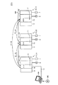
図1は、本発明の実施の形態に係るPLCシステムSYSを示す模式図である。本実施の形態に係るPLCシステムSYSは、ネットワークNWを介してネットワーク接続された複数のPLC(PLC1,PLC2,PLC3)を含む。これらのPLCの種別は必ずしも同一ではないとする。 FIG. 1 is a schematic diagram showing a PLC system SYS according to an embodiment of the present invention. The PLC system SYS according to the present embodiment includes a plurality of PLCs (PLC1, PLC2, PLC3) connected via a network NW. These PLC types are not necessarily the same.
本明細書において「PLCの種別」とは、主として、プログラムによるデータの書込み、読出し、更新などの処理において利用(参照)されるデータ構造が同一であるか否かという観点を示すものである。例えば、2つのPLCの間で、いずれのデータ型であっても、一方のPLCが書込んだデータを他方のPLCが本来のデータの意味で解釈できる場合には、「PLCの種別が同一」であるとする。これに対して、あるデータ型について、一方のPLCが書込んだデータを他方のPLCが本来のデータの意味で解釈できない場合には、「PLCの種別が同一ではない(種別が別である)」であるとする。言い換えれば、あるPLCがネットワークNWを介して自装置のデータを送信した場合に、別のPLCがその送信されたデータを受信して正しく解釈できるか否かという観点に着目して、「PLCの種別」が判断される。 In this specification, “PLC type” mainly indicates the viewpoint of whether or not the data structures used (referenced) in processing such as data writing, reading, and updating by the program are the same. For example, if the data written by one PLC can be interpreted by the other PLC in the meaning of the original data, regardless of the data type between the two PLCs, the "PLC types are the same" Suppose that On the other hand, if the data written by one PLC cannot be interpreted by the other PLC in the meaning of the original data for a certain data type, “PLC types are not the same (types are different). ”. In other words, when a certain PLC transmits its own data via the network NW, paying attention to whether another PLC can receive and correctly interpret the transmitted data, “Type” is determined.
以下の説明では、典型例として、PLC1,PLC2,PLC3の間では、種別が異なっているものとする。しかしながら、PLC1とPLC2との間、PLC2とPLC3との間、およびPLC3とPLC1との間では、ネットワークNWを介してデータを遣り取りする必要があるものとする。本実施の形態に係るサポート装置200は、このような状況下において、PLC間でのデータの遣り取りを適合化する。
In the following description, as a typical example, it is assumed that the types are different among PLC1, PLC2, and PLC3. However, it is assumed that data needs to be exchanged between the PLC 1 and the
各PLCは、プログラムを実行する主体である処理ユニット10と、処理ユニット10などへ電力を供給する電源ユニット12と、フィールドからの信号を遣り取りするIO(Input/Output)ユニット14とを含む。IOユニット14は、処理ユニット10とシステムバス11を介して接続されている。典型的には、IOユニット14は、フィールド機器である検出センサー6から入力信号を取得し、また処理ユニット10でのプログラムの実行結果に応じてフィールド機器であるリレー7を駆動する。
Each PLC includes a
サポート装置200は、PLCで実行されるプログラム(以下「実行可能プログラム」とも称す)を生成する機能とともに、接続先のPLCの運転状態や各種データの値などをモニタする機能を有している。さらに、サポート装置200は、ユーザによる実行可能プログラムの生成を支援するため、デバック機能やシミュレーション機能を有していてもよい。
The
<B.ハードウェア構成>
次に、図1に示すPLCシステムSYSを構成するPLCおよびサポート装置200のハードウェア構成について説明する。
<B. Hardware configuration>
Next, the hardware configuration of the PLC and the
(b1:PLCのハードウェア構成)
図2は、本発明の実施の形態に係るPLCの処理ユニット10のハードウェア構成を示す模式図である。図2を参照して、処理ユニット10は、プロセッサ100と、チップセット102と、メインメモリ104と、不揮発性メモリ106と、システムタイマ108と、システムバスコントローラ120と、ネットワークコントローラ140と、USBコネクタ110とを含む。チップセット102と他のコンポーネントとの間は、各種のバスを介してそれぞれ結合されている。
(B1: PLC hardware configuration)
FIG. 2 is a schematic diagram showing a hardware configuration of the
プロセッサ100およびチップセット102は、典型的には、汎用的なコンピュータアーキテクチャに準じて構成される。すなわち、プロセッサ100は、チップセット102から内部クロックに従って順次供給される命令コードを解釈して実行する。チップセット102は、接続されている各種コンポーネントとの間で内部的なデータを遣り取りするとともに、プロセッサ100に必要な命令コードを生成する。さらに、チップセット102は、プロセッサ100での演算処理の実行の結果得られたデータなどをキャッシュする機能を有する。
The
処理ユニット10は、メモリとして、メインメモリ104および不揮発性メモリ106を有する。
The
メインメモリ104は、揮発性の記憶領域であり、処理ユニット10への電源投入後にプロセッサ100で実行されるべき各種プログラムを格納する。メインメモリ104は、プロセッサ100による各種プログラムの実行時の作業用メモリとしても使用される。このようなメインメモリ104としては、DRAM(Dynamic Random Access Memory)やSRAM(Static Random Access Memory)といったデバイスが用いられる。
The
不揮発性メモリ106は、リアルタイムOS(Operating System)、システムプログラム、実行可能プログラムといった各種プログラム(モジュール)、およびシステム設定パラメータといったデータを不揮発的に格納する。これらのプログラムやデータは、必要に応じて、プロセッサ100がアクセスできるようにメインメモリ104にコピーされる。このような不揮発性メモリ106としては、フラッシュメモリのような半導体メモリを用いることができる。あるいは、ハードディスクドライブのような磁気記録媒体や、DVD−RAM(Digital Versatile Disk Random Access Memory)のような光学記録媒体などを用いることもできる。
The
システムタイマ108は、一定周期ごとに割り込み信号を発生してプロセッサ100に提供する。典型的には、ハードウェアの仕様によって、複数の異なる周期でそれぞれ割り込み信号を発生するように構成されるが、OS(Operating System)やBIOS(Basic Input Output System)などによって、任意の周期で割り込み信号を発生するように設定することもできる。
The
処理ユニット10は、通信インターフェイスとして、システムバスコントローラ120およびネットワークコントローラ140を有する。これらの通信インターフェイスは、出力データの送信および入力データの受信を行う。
The
システムバスコントローラ120は、システムバス11を介したデータの遣り取りを制御する。より具体的には、システムバスコントローラ120は、DMA(Dynamic Memory Access)制御回路122と、システムバス制御回路124と、バッファメモリ126とを含む。システムバスコントローラ120は、システムバスコネクタ130を介してシステムバス11と内部的に接続される。
The
バッファメモリ126は、システムバス11を介してIOユニット14へ出力されるデータの送信バッファ、および、システムバス11を介してIOユニット14から入力されるデータの受信バッファとして機能する。
The
DMA制御回路122は、メインメモリ104からバッファメモリ126への出力データの転送、および、バッファメモリ126からメインメモリ104への入力データの転送を行う。
The
システムバス制御回路124は、システムバス11に接続されるIOユニット14との間で、バッファメモリ126の出力データを送信する処理および入力データを受信してバッファメモリ126に格納する処理を行う。
The system
ネットワークコントローラ140は、ネットワークNWを介した他のPLCとの間のデータの遣り取りを制御する。すなわち、ネットワークコントローラ140は、用いられるネットワーク規格に従い、出力データの送信および入力データの受信を制御する。一例として、OSI参照モデルの物理層およびデータリンク層としてイーサネット(登録商標)を採用し、OSI参照モデルのネットワーク層およびトランスポート層としてTCP/IPまたはUDP/IPを採用し、OSI参照モデルのセッション層およびプレゼンテーション層として産業用共通プロトコル(CIP:Common Industrial Protocol)を採用したような構成が採用される。
The
上述のようなネットワーク規格に限られることなく、各種の産業用イーサネット(登録商標)を用いることができる。産業用イーサネット(登録商標)としては、たとえば、EtherCAT(登録商標)、Profinet IRT、MECHATROLINK(登録商標)−III、Powerlink、SERCOS(登録商標)−III、CIP Motionなどが知られている。 Various industrial Ethernet (registered trademark) can be used without being limited to the network standards as described above. As industrial Ethernet (registered trademark), for example, EtherCAT (registered trademark), Profinet IRT, MECHATROLINK (registered trademark) -III, Powerlink, SERCOS (registered trademark) -III, and CIP Motion are known.
バッファメモリ146は、ネットワークNWを介して他のPLCへ出力されるデータの送信バッファ、および、ネットワークNWを介して他のPLCから入力されるデータの受信バッファとして機能する。
The
DMA制御回路142は、メインメモリ104からバッファメモリ146への出力データの転送、および、バッファメモリ146からメインメモリ104への入力データの転送を行う。
The
ネットワーク制御回路144は、ネットワークNWに接続される他のPLCとの間で、バッファメモリ146の出力データを送信する処理および入力データを受信してバッファメモリ146に格納する処理を行う。典型的には、ネットワーク制御回路144は、ネットワークNWにおける物理層およびデータリンク層の機能を提供する。
The
USBコネクタ110は、サポート装置200と処理ユニット10とを接続するための通信インターフェイスである。典型的には、サポート装置200から転送される、処理ユニット10のプロセッサ100で実行可能なプログラムなどは、USBコネクタ110を介してPLCに取込まれる。
The
(b2:サポート装置のハードウェア構成)
図3は、本発明の実施の形態に係るサポート装置200のハードウェア構成を示す模式図である。図3を参照して、サポート装置200は、典型的には、汎用のコンピュータで構成される。なお、メンテナンス性の観点からは、可搬性に優れたノート型のパーソナルコンピュータが好ましい。
(B2: Hardware configuration of support device)
FIG. 3 is a schematic diagram showing a hardware configuration of the
図3を参照して、サポート装置200は、OSを含む各種プログラムを実行するCPU201と、BIOSや各種データを格納するROM(Read Only Memory)202と、CPU201でのプログラムの実行に必要なデータを格納するための作業領域を提供するメモリRAM203と、CPU201で実行されるプログラムなどを不揮発的に格納するハードディスク(HDD)204とを含む。
With reference to FIG. 3, the
サポート装置200は、さらに、ユーザからの操作を受け付けるキーボード205およびマウス206と、情報をユーザに提示するためのモニタ207とを含む。サポート装置200は、PLC(処理ユニット10)などと通信するための通信インターフェイス(IF)209を含む。
The
後述するように、サポート装置200で実行される各種プログラムは、CD−ROM300に格納されて流通する。このCD−ROM300に格納されたプログラムは、CD−ROM(Compact Disk-Read Only Memory)ドライブ208によって読取られ、ハードディスク(HDD)204などへ格納される。あるいは、上位のホストコンピュータなどからネットワークを通じてプログラムをダウンロードするように構成してもよい。
As will be described later, various programs executed by the
<C.ソフトウェア構成>
(c1:PLCのソフトウェア構成)
次に、PLC(処理ユニット10)が各種機能を提供するためのソフトウェア構成について説明する。
<C. Software configuration>
(C1: PLC software configuration)
Next, a software configuration for the PLC (processing unit 10) to provide various functions will be described.
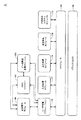
図4は、本発明の実施の形態に係るPLCの処理ユニット10に実装されるソフトウェア構成を示す模式図である。図4に示すソフトウェアに含まれる命令コードは、適切なタイミングで読出され、処理ユニット10のプロセッサ100へ提供されて実行される。
FIG. 4 is a schematic diagram showing a software configuration implemented in the
図4を参照して、処理ユニット10には、リアルタイムOS190上にPLCでの処理に必要なプログラムが実装される。
Referring to FIG. 4, a program necessary for processing by the PLC is mounted on the real-
リアルタイムOS190は、処理ユニット10のコンピュータアーキテクチャに応じて設計されており、プロセッサ100がPLCでの処理に必要なプログラムを実行するための基本的な実行環境を提供する。より具体的には、リアルタイムOS190は、複数のプログラムを時間の経過に従い切り替えて実行するための環境を提供する。リアルタイムOS190は、制御サイクル開始の割り込みが発生すると、プロセッサ100での実行対象を、割り込み発生時点で実行中のプログラムからスケジューラ160に切り替える。
The real-
本実施の形態に係る実行可能プログラムとしては、基本的には、ユーザ定義アプリケーション170が想定されている。ユーザ定義アプリケーション170は、サポート装置200によって生成され、サポート装置200から処理ユニット10へ転送される。なお、ユーザ定義アプリケーション170の実行に必要な一部のモジュール(あるいは、ライブラリ)については、処理ユニット10に予め格納されており、これらを適切なタイミングで呼び出して利用する形態(シンボリックリンク)を採用してもよい。この場合、サポート装置200は、一部のモジュールを含まない実行可能プログラムを生成することになる。あるいは、ユーザ定義アプリケーション170および命令実行モジュール180を含めて、実行可能プログラムとしてもよい。
As an executable program according to the present embodiment, a user-defined
より具体的には、処理ユニット10には、スケジューラ160と、ユーザ定義アプリケーション170と、入力処理モジュール172と、出力処理モジュール174と、通信処理モジュール176と、その他のシステムモジュール178と、命令実行モジュール180と、メモリマネジャー184と、データ構造変換モジュール186とが実装される。
More specifically, the
スケジューラ160は、ユーザ定義アプリケーション170、入力処理モジュール172、出力処理モジュール174、および通信処理モジュール176について、実行開始タイミングや処理中断を制御することで、各実行サイクルでの処理を保証する。より具体的には、1つの制御サイクル内ですべての処理を完了できないことも多く、この場合には、スケジューラ160は、実行すべき処理の優先度などに応じて、各制御サイクルにおいて実行を完了すべき処理と、複数の制御サイクルに亘って実行してもよい処理とを区分する。すなわち、スケジューラ160は、各制御サイクル期間内において、より高い優先度が与えられているプログラムほど先に実行する。
The
ユーザ定義アプリケーション170は、ユーザがその制御目的に応じて作成する。すなわち、PLCシステムSYSを用いて制御する対象のライン(プロセス)などに応じて、任意に設計されるプログラムである。より具体的には、ユーザ定義アプリケーション170は、サポート装置200などにおいて、ラダー言語などによって記述されたソースプログラムがコンパイルされることで生成される。生成された実行可能(オブジェクト)プログラム形式のユーザ定義アプリケーション170は、サポート装置200から接続ケーブル13を介して処理ユニット10へ転送され、不揮発性メモリ106などに格納される。
The user-defined
ユーザ定義アプリケーション170は、シーケンス処理およびモーション演算などの特殊処理を含み得る。ユーザ定義アプリケーション170は、命令実行モジュール180と協働して、ユーザ定義アプリケーション170に含まれる処理を実現する。より具体的には、ユーザ定義アプリケーション170は、命令実行モジュール180によって提供される命令や関数などを利用することで、プログラムされた動作を実現する。
The user-defined
命令実行モジュール180は、ユーザ定義アプリケーション170に定義された何らかのシーケンス命令あるいは何らかのファンクション命令が実行されるときに呼び出される。
The
入力処理モジュール172は、システムバスコントローラ120によって受信された入力データを、ユーザ定義アプリケーション170が使用するのに適した形式に再配置する。出力処理モジュール174は、ユーザ定義アプリケーション170の実行によって生成された出力データを、システムバスコントローラ120へ転送するのに適した形式に再配置する。
通信処理モジュール176は、ネットワークコントローラ140による他のPLCとの間の通信処理のタイミングを制御する。通信処理モジュール176は、さらに、ネットワークコントローラ140が他のPLCから受信された入力データをユーザ定義アプリケーション170が使用するのに適した形式に再配置するとともに、ユーザ定義アプリケーション170の実行によって生成された出力データを、ネットワークコントローラ140へ転送するのに適した形式に再配置する。
The
その他のシステムモジュール178は、図4に個別に示したプログラム以外の、PLC1の各種機能を実現するための1つまたは複数のモジュールをまとめて示したものである。
The
メモリマネジャー184は、メインメモリ104に格納されるデータを管理する。
データ構造変換モジュール186は、他のPLCとの間でデータ交換を行うために、データ構造をPLCの種別毎に定義されるデータ構造に適合させる。すなわち、データ構造変換モジュール186は、自PLCが扱うデータのデータ構造を他のPLCが扱うデータ構造に変換する。
The
The data
上述した、実行可能プログラム(ユーザ定義アプリケーション170単体またはユーザ定義アプリケーション170および命令実行モジュール180)は、記憶手段であるメインメモリ104および/または不揮発性メモリ106に格納される。
The above-described executable program (the user-defined
(c2:サポート装置のソフトウェア構成)
次に、サポート装置200が各種機能を提供するためのソフトウェア構成について説明する。
(C2: Software configuration of support device)
Next, a software configuration for the
図5は、本発明の実施の形態に係るサポート装置200に実装されるソフトウェア構成を示す模式図である。図5に示すソフトウェアに含まれる命令コードは、適切なタイミングで読出され、サポート装置200のCPU201へ提供されて実行される。
FIG. 5 is a schematic diagram showing a software configuration implemented in the
図5を参照して、サポート装置200には、OS240、プログラミングアプリケーション250およびネットワーク設定アプリケーション280が実装される。サポート装置200ではOS240が実行され、プログラミングアプリケーション250およびネットワーク設定アプリケーション280を実行可能な環境が提供される。本実施の形態に係るサポート装置200を実現するためのサポートプログラムは、少なくともプログラミングアプリケーション250を含む。
With reference to FIG. 5, an
プログラミングアプリケーション250は、エディタ252と、コンパイラ254と、デバッガ256と、GUI(Graphical User Interface)モジュール258と、シミュレータ260と、データ格納部270とを含む。プログラミングアプリケーション250に含まれるそれぞれのモジュールは、典型的には、CD−ROM300に格納された状態で流通して、サポート装置200にインストールされる。
The
エディタ252は、実行可能プログラム(ソースプログラム274)を作成するための入力および編集といった機能を提供する。より具体的には、エディタ252は、ユーザがキーボード205やマウス206を操作してユーザ定義アプリケーション170のソースプログラム274を作成する機能に加えて、作成したソースプログラム274の保存機能および編集機能を提供する。
The
コンパイラ254は、ユーザ定義アプリケーション170のソースプログラム274をコンパイルして、処理ユニット10のプロセッサ100で実行可能(オブジェクト)プログラム形式の実行可能プログラムを生成する機能を提供する。
The
デバッガ256は、実行可能プログラム(ソースプログラム274)に対してデバッグを行うための機能を提供する。このデバッグの内容としては、ソースプログラム274のうちユーザが指定した範囲を部分的に実行する、ソースプログラム274の実行中における変数値の時間的な変化を追跡する、といった動作を含む。
The
GUIモジュール258は、ユーザが各種データやパラメータなどを入力するためのユーザインターフェイスを提供する機能を有する。
The
シミュレータ260は、サポート装置200内にPLC1の処理ユニット10でのプログラムの実行をシミュレーションする環境を構築する。
The
データ格納部270は、ユーザが作成したソースプログラム274やプログラムの実行に必要な変数設定272を格納する。
The
ネットワーク設定アプリケーション280は、PLC間のデータの遣り取りに係る設定を行うための機能を提供する。ネットワーク設定アプリケーション280は、エディタ282と、コンフィグレータ284と、関連付けモジュール286と、データ格納部290とを含む。ネットワーク設定アプリケーション280に含まれるそれぞれのモジュールは、典型的には、CD−ROM300に格納された状態で流通して、サポート装置200にインストールされる。
The
エディタ282は、PLC間で遣り取りされるデータ(変数)の設定情報の入力および編集といった機能を提供する。より具体的には、エディタ282は、ユーザがキーボード205やマウス206を操作して、PLC間で遣り取りされる変数などを指定する機能に加えて、入力された設定情報の保存機能および編集機能を提供する。また、エディタ282は、ネットワーク接続されたPLCからその変数設定などを取得(ダウンロード)することもできる。
The
コンフィグレータ284は、PLC間でデータを遣り取りするための設定を対象のPLCへ設定する機能を提供する。このコンフィグレータ284によって各PLCへ設定される情報をコネクション設定296とも称す。
The
関連付けモジュール286は、遣り取りされるデータ毎に、対象のPLC間の関連付けを行う機能を提供する。すなわち、関連付けモジュール286は、PLCの別にコネクション設定296を生成する。
The
データ格納部290は、PLCから取得した変数の情報を示す変数設定292,294およびコネクション設定296を格納する。
The
<D.変数設定>
上述したように、本実施の形態に係るPLC(処理ユニット10)は、プロセッサ100と、メインメモリ104および不揮発性メモリ106と、ネットワークインターフェイスであるネットワークコントローラ140とを含み、サポート装置200で生成された実行可能プログラムを実行する。この実行可能プログラムは、変数プログラムであり、サポート装置200で作成されるソースプログラム274がコンパイルすることで生成される。このソースプログラム274では、組み合わせられる命令を記述するために、変数を用いて各データが指定される。そのため、サポート装置200は、PLCで扱われるデータ別に変数を定義する情報を受け付ける。より具体的には、ユーザは、サポート装置200によって提供されるユーザインターフェイスを介して、実行可能プログラムで使用する変数、およびその変数に対応するデータの型を定義する。
<D. Variable settings>
As described above, the PLC (processing unit 10) according to the present embodiment includes the
図6は、本発明の実施の形態に係るサポート装置200が提供する変数を定義するためのユーザインターフェイスの一例である。
FIG. 6 is an example of a user interface for defining variables provided by the
図6を参照して、ユーザインターフェイスである変数定義画面400は、変数やデータ型を定義するための領域410と、後述する他のPLCとの間でネットワークNWを介して遣り取りするための設定を入力するための領域420とを含む。図6には、変数やデータ型の定義と他のPLCとの間のデータ供給に係るネットワーク設定とを同一のユーザインターフェイスで提供する例を示すが、これらの入力形態は任意に設計すればよく、領域410に係る入力画面と、領域420に係る入力画面とを別々に提供するようにしてもよい。
Referring to FIG. 6, a
より具体的には、領域410は、変数(名称)を入力するためのカラム412と、対応する変数のデータの型を入力するためのカラム414と、データ型が集合体(配列型変数または構造体変数)である場合に対応する変数(要素/メンバ)が集合体のうちいずれの位置に対応する変数が格納されるかを入力するためのカラム416および418を含む。すなわち、対応する変数のデータの開始点がバイト(8ビット)とビットとの組み合わせで表現され、バイト数およびビット数がそれぞれカラム416および418へ入力される。
More specifically, the
カラム412に入力される変数(名称)は、ユーザが任意に決定することができる。
カラム414に入力されるデータ型としては、その使用目的に応じて予め用意された複数種類から選択される。図6には、変数「StrA」に対応付けて「STRUCT」が指定されており、これは、構造体変数を意味する。また、変数「mb」および「mi」に対応付けてそれぞれ「BOOL」および「INT」が指定されており、これらはそれぞれ「ビット」および「符号付き1ワードバイナリー」を意味する。
The variable (name) input to the
The data type input to the
データ型としては、上述するもの以外に、SINT(符号付き1バイトバイナリー)、INT(符号付き1ワードバイナリー)、DINT(符号付き2ワードバイナリー)、LINT(符号付き4ワードバイナリー)、USINT(符号なし1バイトバイナリー)、UINT(符号なし1ワードバイナリー)、UDINT(符号なし1ワードバイナリー)、ULINT(符号なし4ワードバイナリー)、REAL(浮動小数点2ワード)、LREAL(浮動小数点4ワード)、BYTE(16進1バイト)、WORD(16進1ワード)、DWORD(16進2ワード)、LWORD(16進4ワード)などを指定することができる。なお、各PLCが上述したデータ型のすべてをサポートしている必要はなく、その一部のみをサポートしている場合もある。
Data types other than those described above are SINT (signed 1-byte binary), INT (signed 1-word binary), DINT (signed 2-word binary), LINT (signed 4-word binary), USINT (signed) None 1-byte binary), UINT (unsigned 1-word binary), UDINT (unsigned 1-word binary), ULINT (unsigned 4-word binary), REAL (floating
上述のように定義された変数を用いて、ユーザは、ソースプログラム274を作成することができる。すなわち、サポート装置200は、PLCで実行される処理を、定義された変数を用いて記述したソースプログラム274を受け付ける。
Using the variables defined as described above, the user can create a
<E.ネットワークを介したデータの遣り取り>
(e1:概要)
次に、本実施の形態に係るPLCシステムSYSでは、ネットワークNWを介して、PLC間でデータを遣り取りすることが可能である。このデータを遣り取りする際にも、変数を用いて対象のデータを特定することができる。
<E. Exchange of data via network>
(E1: Overview)
Next, in the PLC system SYS according to the present embodiment, it is possible to exchange data between PLCs via the network NW. Even when this data is exchanged, the target data can be specified using a variable.
上述のサポート装置200で実行されるネットワーク設定アプリケーション280がPLC間で遣り取りされるデータを示す変数の対応関係を決定し、それぞれのPLCに設定する。すなわち、図5に示すコネクション設定296が決定され、それぞれのPLCに対して転送される。
The
まず、PLC間で遣り取りされるデータ(変数値)は、予めネットワーク公開の対象であること(ネットワーク公開属性)が設定される。具体的には、上述の図6において、領域420に含まれるカラム422には、ネットワーク公開属性として、「出力」、「入力」、「公開のみ」といった値が設定される。これにより、PLCの内部で使用されているデータ(変数値)がネットワーク接続された他のPLCからアクセス可能になる。なお、このネットワーク公開できる変数(ネットワーク変数)は、実行可能プログラムにおいてグローバル変数として使用されているものに限定してもよい。
First, data (variable values) exchanged between PLCs is set in advance as a network disclosure target (network disclosure attribute). Specifically, in FIG. 6 described above, in the
この公開先の情報は、後述のPLCの種別を特定する際にも利用される。すなわち、サポート装置200は、PLC1で用いられる変数に関連付けてPLC2の種別を特定する情報を受け付ける。
This disclosure destination information is also used when specifying the type of PLC described later. That is, the
また、領域420に含まれるカラム424には、対応する変数の公開先を特定するための情報が格納される。この公開先を特定するための情報としては、典型的には、IPアドレスやMACアドレスが用いられる。あるいは、各PLCが保有する識別情報(機種情報やメーカ情報を含む)であってもよい。
Further, the
ネットワークNW上に公開された変数(変数の名称)は「タグ」とも称され、この変数を指定してデータを遣り取りする機能は「タグ通信」機能とも称される。さらに、PLCで実行される実行可能プログラムが扱う変数に代えて、同一の変数値に対して、ネットワークNW上で遣り取りするための「別名」としての変数値を設定することもできる。このような別名を設定する機能は「ネットワークエイリアス」とも称される。このようなネットワークエイリアスを用いることで、PLC内部の変数を外部から隠蔽することができる。 A variable (variable name) disclosed on the network NW is also referred to as a “tag”, and a function for specifying this variable to exchange data is also referred to as a “tag communication” function. Furthermore, a variable value as an “alias” for exchanging on the network NW can be set for the same variable value instead of the variable handled by the executable program executed by the PLC. Such a function for setting an alias is also referred to as a “network alias”. By using such a network alias, it is possible to hide variables in the PLC from the outside.
図7は、本発明の実施の形態に係るPLCシステムSYSにおけるネットワークを介したデータの遣り取りを説明するための図である。より具体的には、図7(a)は、PLC内部の変数がそのままネットワーク変数として利用される場合の処理を示し、図7(b)は、ネットワークエイリアスを設定した場合の処理を示す。 FIG. 7 is a diagram for explaining exchange of data via the network in the PLC system SYS according to the embodiment of the present invention. More specifically, FIG. 7A shows processing when a variable in the PLC is directly used as a network variable, and FIG. 7B shows processing when a network alias is set.
図7(a)を参照して、PLC1においては、内部変数「StrA」が定義されるとともに、内部変数「StrA」に対して、ネットワーク公開属性および公開先(この例では、PLC2)が設定される。一方、PLC2においては、ネットワークNWを介して受信するデータに対して内部変数「B_input」が定義されるとともに、内部変数「StrA」に対して、ネットワーク公開属性が設定される。また、PLC1およびPLC2には、内部変数「StrA」と内部変数「B_input」との対応関係がそれぞれ設定されているものとする。これらの対応関係の設定方法については、後述する。
Referring to FIG. 7A, in PLC1, an internal variable “StrA” is defined, and a network public attribute and a disclosure destination (in this example, PLC2) are set for internal variable “StrA”. The On the other hand, in the
上述のような変数の定義やネットワーク属性の設定などによって、PLC1で順次更新される内部変数「StrA」に格納される値(データ)は、PLC2においては、その内部変数「B_input」として内部処理に利用することが可能である。
The value (data) stored in the internal variable “StrA” that is sequentially updated in the PLC 1 by the variable definition and the network attribute setting as described above is used as internal variable “B_input” in the internal processing in the
さらに、図7(b)には、PLC1の内部変数「StrA」をネットワーク変数「Tag1」としてネットワーク公開する例を示す。このとき、ネットワーク変数を定義するためのネットワーク変数テーブルに、内部変数「StrA」がネットワーク変数「Tag1」に対応することが定義されるとともに、対応するネットワーク公開属性(この例では「出力」)が設定される。PLC2は、ネットワークNW上でネットワーク変数「Tag1」を指定することで、PLC1の内部変数「StrA」に格納される値(データ)を内部処理に利用することができる。
Further, FIG. 7B shows an example in which the internal variable “StrA” of the PLC 1 is disclosed to the network as the network variable “Tag 1”. At this time, it is defined in the network variable table for defining the network variable that the internal variable “StrA” corresponds to the network variable “Tag1”, and the corresponding network public attribute (“output” in this example) is Is set. The
(e2:設定)
次に、上述のようなPLC間でのデータの遣り取りに必要な対応関係(名前解決)の設定について説明する。
(E2: Setting)
Next, the setting of the correspondence (name resolution) necessary for the exchange of data between the PLCs as described above will be described.
図8は、本発明の実施の形態に係るPLCシステムSYSにおけるPLC間でのデータの遣り取りに必要な対応関係の設定方法を説明するための図である。サポート装置200で実行されるプログラミングアプリケーション250は、それぞれPLC1およびPLC2で使用される変数を定義する変数設定1および変数設定2を保持しているものとする。プログラミングアプリケーション250は、それぞれのPLCの変数設定292,294を比較して変数間の対応関係を決定し、その対応関係を反映したコネクション設定296を生成する。
FIG. 8 is a diagram for explaining a correspondence setting method necessary for data exchange between PLCs in the PLC system SYS according to the embodiment of the present invention. It is assumed that the
説明の便宜上、図8においては、単一のサポート装置200において2つのプログラミングアプリケーション250が実行される例を示すが、PLCの別にサポート装置200が用意される場合には、各サポート装置200においてプログラミングアプリケーション250が実行される。この場合には、公知の方法を用いて、それぞれのPLCの変数設定がネットワーク設定アプリケーション280へ出力(import)される。
For convenience of explanation, FIG. 8 shows an example in which two
そして、ネットワーク設定アプリケーション280は、生成したコネクション設定296に基づいて、PLC1およびPLC2のそれぞれに対して、内部変数とネットワーク変数との対応関係を定義するタグデータリンク設定を出力(ダウンロード)する。
Then, based on the generated connection setting 296, the
PLC1およびPLC2は、ネットワーク設定アプリケーション280から受信したタグデータリンク設定に従ってネットワークを構成することで、他のPLCとの間でデータを遣り取りできる。なお、タグデータリンク設定は、タグ(変数/変数の名称)、タグセット(タグ同士の対応関係)、コネクション設定などを含む。
The PLC 1 and the
このように、サポート装置200は、PLC1で扱われるデータを示す変数(タグ)と、PLC1とネットワーク接続されたPLC2で扱われるデータを示す変数(タグ)とをネットワークNWを介して対応付けるための対応関係を受け付ける。そして、サポート装置200は、この対応関係に基づいて、データを遣り取りするそれぞれのPLCについてのネットワークを設定する。
As described above, the
<F.データ構造の相違>
上述のようなネットワークNWを介したデータの遣り取りにおいて、対象のデータを各PLCの内部で扱うデータのまま他のPLCへ送信されるような形態を考える。すなわち、PLC内部のメモリデータそのものが他のPLCへ渡される。この場合、PLC間における扱うデータ構造(データフォーマット)の相違によって、データを適切に遣り取りできない場合がある。図9には、このようなデータ構造の相違の一例を示す。
<F. Differences in data structure>
In the exchange of data via the network NW as described above, a mode is considered in which target data is transmitted to other PLCs as data handled inside each PLC. That is, the memory data itself in the PLC is passed to another PLC. In this case, data may not be exchanged appropriately due to a difference in data structure (data format) handled between PLCs. FIG. 9 shows an example of such a data structure difference.
図9は、本発明の実施の形態に係るPLCシステムSYSにおけるPLC間におけるデータ構造の相違の一例を示す図である。図9には、集合体のデータ型の例を示すが、これに限られることなく、様々なデータ構造の相違が考えられる。後述するように、本実施の形態に係るサポート装置200は、このようなデータ構造の相違を適合化した実行可能プログラムを生成する。
FIG. 9 is a diagram illustrating an example of a difference in data structure between PLCs in the PLC system SYS according to the embodiment of the present invention. FIG. 9 shows an example of the data type of the aggregate. However, the present invention is not limited to this, and various data structure differences can be considered. As will be described later, the
図9(a)には、構造体変数が定義されるとともに、BOOL(ビット)である変数aおよび変数bがそのメンバとして定義される例を示す。例えば、PLC1では、その構造体変数として2ワード分の領域が確保されるとともに、1ワード目の最下位ビットに変数aの値が格納され、2ワード目の最下位ビットに変数bの値が格納されるものとする。 FIG. 9A shows an example in which a structure variable is defined and a variable a and a variable b which are BOOT (bits) are defined as members. For example, in PLC1, an area for two words is secured as the structure variable, the value of variable a is stored in the least significant bit of the first word, and the value of variable b is stored in the least significant bit of the second word. Shall be stored.
これに対して、同様の構造体変数を定義した場合であっても、PLC2およびPLC3内部のメモリデータは異なったフォーマットであるとする。例えば、PLC2では、その構造体変数として2ワード分の領域が確保されるとともに、1ワード目の最下位ビットに変数aの値が格納され、当該最下位ビットの次に位置するビットに変数bの値が格納されるものとする。また、PLC3では、その構造体変数として1ワード分の領域が確保されるとともに、最下位ビットに変数aの値が格納され、当該最下位ビットの次に位置するビットに変数bの値が格納されるものとする。 On the other hand, even if similar structure variables are defined, it is assumed that the memory data in PLC2 and PLC3 have different formats. For example, in PLC2, an area for two words is secured as the structure variable, the value of the variable a is stored in the least significant bit of the first word, and the variable b is set in the bit positioned next to the least significant bit. The value of is stored. In PLC3, an area for one word is secured as the structure variable, the value of variable a is stored in the least significant bit, and the value of variable b is stored in the bit positioned next to the least significant bit. Shall be.
図9(b)には、構造体変数が定義されるとともに、INT(符号付き1ワードバイナリー)である変数w0がそのメンバとして定義される例を示す。例えば、PLC1では、その構造体変数として1ワード分の領域が確保されるとともに、その全体に変数w0のデータ値(1ワード)が格納されるものとする。また、PLC3においても同様のデータ構造が採用される。 FIG. 9B shows an example in which a structure variable is defined and a variable w0 that is INT (signed 1-word binary) is defined as its member. For example, in PLC1, an area for one word is secured as the structure variable, and the data value (1 word) of the variable w0 is stored in the whole. A similar data structure is also adopted in the PLC 3.
これに対して、PLC2では、その構造体変数として2ワード分の領域が確保されるとともに、1ワード目に変数w0のデータ値(1ワード)が格納され、2ワード目はnull(あるいは、ダミーデータ)になるものとする。 On the other hand, in PLC2, an area for two words is secured as the structure variable, and the data value (1 word) of the variable w0 is stored in the first word, and the second word is null (or a dummy). Data).
図9(c)には、構造体変数が定義されるとともに、INT(符号付き1ワードバイナリー)である変数w0およびDINT(符号付き2ワードバイナリー)である変数d0がそのメンバとして定義される例を示す。例えば、PLC1では、その構造体変数として4ワード分の領域が確保されるとともに、1ワード目に変数w0のデータ値(1ワード)が格納され、2ワード目はnullになり、3ワード目および4ワード目に変数d1のデータ値(2ワード)が格納されるものとする。また、PLC2においても同様のデータ構造が採用される。 FIG. 9C shows an example in which a structure variable is defined and a variable w0 that is INT (signed 1-word binary) and a variable d0 that is DINT (signed 2-word binary) are defined as its members. Indicates. For example, in PLC1, an area for 4 words is secured as the structure variable, the data value (1 word) of the variable w0 is stored in the first word, the second word is null, the third word and It is assumed that the data value (2 words) of the variable d1 is stored in the fourth word. The same data structure is also adopted in PLC2.
これに対して、PLC3では、その構造体変数として3ワード分の領域が確保されるとともに、1ワード目に変数w0のデータ値(1ワード)が格納され、2ワード目および3ワード目に変数d1のデータ値(2ワード)が格納されるものとする。 On the other hand, in PLC3, an area for three words is secured as the structure variable, and the data value (1 word) of the variable w0 is stored in the first word, and the variable in the second and third words. It is assumed that the data value (2 words) of d1 is stored.
上述したように、PLC1,PLC2,PLC3の間では、一部のデータ型のデータ構造については共通であるが、他のデータ型のデータ構造については相違しているような状況が生じる。 As described above, some data types have the same data structure between PLC1, PLC2, and PLC3, but other data types have different data structures.
<G.データ構造の適合化処理>
上述したように、本実施の形態に係るPLCの処理ユニット10は、タグ名を指定してネットワーク変数の読出し/書込みを行う機能を有する。処理ユニット10(図4の通信処理モジュール176)は、変数にデータ値を書込むときには、変数のデータ型やチェックビット(構造体変数の場合は、CRC:Cyclic Redundancy Check)をチェックして、意図しないデータ型へのデータ値の書込みを防止する機能を有する。なお、構造体変数のCRCは、構造体変数のデータ型の情報に基づいて動的に算出される。また、処理ユニット10(図4の通信処理モジュール176)は、受信したメッセージについてのCRCチェックを行う。
<G. Data structure adaptation processing>
As described above, the
上述したように、PLC間でデータが遣り取りされる場合には、PLC内部の変数がそのままネットワーク変数として送出される。そのため、PLC間でデータ構造が異なっていると、上述のようなデータ型やCRCのチェックでエラーが発生する。また、データ構造が異なっているため、PLC間で本来的に意図されたデータの遣り取りを行うことができない。 As described above, when data is exchanged between PLCs, variables in the PLC are transmitted as they are as network variables. Therefore, if the data structure is different between PLCs, an error occurs in the data type and CRC check as described above. Further, since the data structures are different, originally intended data cannot be exchanged between PLCs.
そこで、本実施の形態に係るサポート装置200は、上述したようなデータ構造(データのアライメント)の相違を吸収して、ユーザが意識しなくとも、任意のPLC間でのデータの遣り取りを行うことができる実行可能プログラムを生成する。以下の説明では、PLC2およびPLC3は、固有のデータ構造のまま処理を行うものとし、PLC1をPLC2およびPLC3に適合させるような形態を考える。但し、いずれのPLCを適合させてもよい。
Therefore, the
図10は、本発明の実施の形態に係るサポート装置200が生成した実行可能プログラムによって実行されるPLC1での処理を説明するための図である。図10に示す例では、図9(c)に示すようなデータ構造の変数を、PLC1とPLC2との間、および、PLC1とPLC3との間で遣り取りする場合の処理例を示す。図9(c)に示すように、PLC1とPLC2との間ではデータ構造は一致しているが、PLC1とPLC3との間ではデータ構造は相違しているとする。
FIG. 10 is a diagram for explaining processing in the PLC 1 that is executed by the executable program generated by the
(1:PLC1とPLC2との間)
まず、PLC1とPLC2との間で遣り取りされる変数(構造体変数)について説明する。この場合、データ構造の相違を考慮する必要がないので、通常の処理が実行される。
(1: Between PLC1 and PLC2)
First, variables (structure variables) exchanged between PLC1 and PLC2 will be described. In this case, since it is not necessary to consider the difference in data structure, normal processing is executed.
より具体的には、PLC1における実行可能プログラムの実行によって、対象の変数値が更新されると(処理P11)、処理ユニット10のプロセッサ100は、当該更新された変数値が格納されるメモリ(典型的には、メインメモリ104)上のアドレスを特定する(処理P12A)。そして、プロセッサ100は、整合性チェック(処理P13A)を行った後、当該更新値を指定されたメモリ上のアドレスに書込む(処理P14A)。
More specifically, when the target variable value is updated by executing the executable program in the PLC 1 (process P11), the
また、PLC1における実行可能プログラムの実行によって、いずれかの変数値が要求されると、処理ユニット10のプロセッサ100は、メモリに格納されているデータ(変数値)を読出し(処理P21A)、読出したデータのCRCなどに基づいてエラーチェック(処理P22A)を行った上で、当該変数値を応答する(処理P23)。
Further, when any variable value is requested by the execution of the executable program in the PLC 1, the
また、PLC2からネットワーク変数のデータ(変数値)を受信すると(処理P31)、処理ユニット10のプロセッサ100は、当該受信された変数値が格納されるべきメモリ(典型的には、メインメモリ104)上のアドレスを特定する(処理P32A)。そして、プロセッサ100は、整合性チェック(処理P33A)を行った後、当該更新値を指定されたメモリ上のアドレスに書込む(処理P34A)。
Further, upon receiving network variable data (variable value) from the PLC 2 (process P31), the
また、PLC2からネットワーク変数のデータ(変数値)が要求されると、処理ユニット10のプロセッサ100は、メモリに格納されているデータ(変数値)を読出し(処理P41A)、読出したデータにCRCなどにチェックビットを付加(処理P42A)する。そして、プロセッサ100は、要求されたデータ(変数値)の送信先を特定(処理P43)した上で、当該変数値を送信する(処理P44)。
Further, when network variable data (variable value) is requested from the
(2:PLC1とPLC3との間)
これに対して、データ構造の異なるPLC3との間でデータを遣り取りする場合には、以下のような手順となる。
(2: Between PLC1 and PLC3)
On the other hand, when data is exchanged with the PLC 3 having a different data structure, the procedure is as follows.
すなわち、PLC1における実行可能プログラムの実行によって、対象の変数値が更新されると(処理P11)、処理ユニット10のプロセッサ100は、当該更新された変数値が格納されるメモリ(典型的には、メインメモリ104)上のアドレスを特定する(処理P12B)。この際、メモリ上にはPLC3で扱われるデータ構造に対応してデータが格納されるので、アドレスの特定には、PLC1で扱われるデータ構造に応じた算出方法ではなく、PLC3で扱われるデータ構造に応じた算出方法が採用される。そして、プロセッサ100は、整合性チェックを行う(処理P13B)。この整合性チェックについても、PLC3で扱われるデータ構造に応じた算出方法が採用される。さらに、プロセッサ100は、当該更新値を指定されたメモリ上のアドレスに書込む(処理P14B)。この際、プロセッサ100は、PLC3で扱われるデータ構造に応じたデータ構造でメモリにデータを書込む。すなわち、データ構造が変換される。このように、PLC1で実行される実行可能プログラムは、PLC1の対象のデータ型に対応する他の他のPLCにおけるデータ構造に従って、対象のデータ(変数値)をメモリに格納するための命令を含む。
That is, when the target variable value is updated by the execution of the executable program in the PLC 1 (process P11), the
また、PLC1における実行可能プログラムの実行によって、いずれかの変数値が要求されると、処理ユニット10のプロセッサ100は、メモリに格納されているデータ(変数値)を読出し(処理P21B)、読出したデータのCRCなどに基づいてエラーチェックを行う(処理P22B)。データ(変数値)の読出しにおいては、PLC1で扱われるデータ構造への変換が行われる。また、このエラーチェックについても、PLC3で扱われるデータ構造に応じた算出方法が採用される。そして、プロセッサ100は、当該変数値を応答する(処理P23)。
When any variable value is requested by the execution of the executable program in the PLC 1, the
また、PLC3からネットワーク変数のデータ(変数値)を受信すると(処理P31)、処理ユニット10のプロセッサ100は、当該受信された変数値が格納されるべきメモリ(典型的には、メインメモリ104)上のアドレスを特定する(処理P32B)。この際、アドレスの特定には、PLC1で扱われるデータ構造に応じた算出方法ではなく、PLC3で扱われるデータ構造に応じた算出方法が採用される。そして、プロセッサ100は、整合性チェックを行う(処理P33B)。この整合性チェックについても、PLC3で扱われるデータ構造に応じた算出方法が採用される。さらに、プロセッサ100は、当該更新値を指定されたメモリ上のアドレスに書込む(処理P34B)。
In addition, when network variable data (variable value) is received from the PLC 3 (process P31), the
また、PLC3からネットワーク変数のデータ(変数値)が要求されると、処理ユニット10のプロセッサ100は、メモリに格納されているデータ(変数値)を読出し(処理P41B)、読出したデータにCRCなどにチェックビットを付加(処理P42B)する。データ(変数値)の読出しおよびエラーチェックについても、PLC3で扱われるデータ構造に応じた算出方法が採用される。そして、プロセッサ100は、要求されたデータ(変数値)の送信先を特定(処理P43)した上で、当該変数値を送信する(処理P44)。
When network variable data (variable value) is requested from the PLC 3, the
上述したように、PLC1で実行される実行可能プログラムは、PLC1の対象のデータ型に対応する他の他のPLCにおけるデータ構造に従って、対象のデータ(変数値)をメモリに格納するための命令を含む。このようなデータ構造に従って対象のデータ(変数値)をメモリに格納するための命令としては、以下のような命令がある。 As described above, the executable program executed in the PLC 1 has an instruction for storing the target data (variable value) in the memory in accordance with the data structure in the other PLC corresponding to the target data type of the PLC 1. Including. Examples of instructions for storing target data (variable values) in a memory according to such a data structure include the following instructions.
(a)PLC1で扱われるデータ(変数値)に含まれる要素(メンバ)の順序を入れ替えてメモリに格納する命令(図9(a)に示すデータ構造などに適用される)
(b)PLC1で扱われるデータ(変数値)にダミー要素を加えた上でメモリに格納する命令(図9(b)や図9(c)に示すデータ構造などに適用される)
(c)PLC1で扱われるデータ(変数値)からダミー要素を除いた上でメモリに格納する命令(図9(b)や図9(c)に示すデータ構造などに適用される)
なお、PLC1に外部装置(パーソナルコンピュータや表示装置)などが接続される場合には、基本的には、PLC1で扱われるデータ構造のデータ(変数値)が出力されることが好ましい。そのため、PLC1で扱われるデータ構造とは異なるデータ構造で格納されているデータ(変数値)については、外部装置へ出力する際に、本来のデータ構造で出力されることが好ましい。図10には、このような場合の処理についても図示する。
(A) Instruction for changing the order of elements (members) included in data (variable values) handled by PLC 1 and storing them in memory (applied to the data structure shown in FIG. 9A)
(B) Instruction to add dummy element to data (variable value) handled by PLC 1 and store in memory (applied to data structure shown in FIGS. 9B and 9C)
(C) Instruction to store dummy memory after removing dummy elements from data (variable value) handled by PLC 1 (applied to data structure shown in FIG. 9B and FIG. 9C)
When an external device (a personal computer or a display device) is connected to the PLC 1, basically, it is preferable to output data (variable values) having a data structure handled by the PLC 1. Therefore, it is preferable that data (variable values) stored in a data structure different from the data structure handled by the PLC 1 is output in the original data structure when output to the external device. FIG. 10 also illustrates processing in such a case.
すなわち、外部装置からネットワーク変数のデータ(変数値)を受信すると(処理P31)、処理ユニット10のプロセッサ100は、当該受信された変数値が格納されるべきメモリ(典型的には、メインメモリ104)上のアドレスを特定する(処理P32C)。この際、アドレスの特定には、現在メモリに格納されているデータ構造に応じた算出方法が採用される。そして、プロセッサ100は、整合性チェックを行う(処理P33C)。この整合性チェックについても、現在メモリに格納されているデータ構造に応じた算出方法が採用される。さらに、プロセッサ100は、当該更新値を指定されたメモリ上のアドレスに書込む(処理P34C)。さらに、プロセッサ100は、当該受信された変数値を指定されたメモリ上のアドレスに書込む(処理P34C)。この際、プロセッサ100は、現在メモリに格納されているデータ構造に応じたデータ構造でメモリにデータを書込む。すなわち、データ構造が変換される。
That is, when network variable data (variable value) is received from an external device (process P31), the
また、外部装置からネットワーク変数のデータ(変数値)が要求されると、処理ユニット10のプロセッサ100は、メモリに格納されているデータ(変数値)を読出し(処理P41C)、読出したデータにCRCなどにチェックビットを付加(処理P42C)する。データ(変数値)の読出しにおいては、PLC1で扱われるデータ構造への変換が行われる。また、このエラーチェックについても、現在メモリに格納されているデータ構造に応じた算出方法が採用される。そして、プロセッサ100は、要求されたデータ(変数値)の送信先を特定(処理P43)した上で、当該変数値を送信する(処理P44)。
Further, when network variable data (variable value) is requested from an external device, the
上述したように、PLC1で実行される実行可能プログラムは、PLC1のメモリに格納されたデータに対する出力要求に応答して、PLC1における指定されたデータの型に対応するデータ構造に変換した上で、変換後のデータを出力する命令を含む。 As described above, the executable program executed in the PLC 1 is converted into a data structure corresponding to the type of data designated in the PLC 1 in response to an output request for data stored in the memory of the PLC 1. Includes instructions to output the converted data.
<H.実行可能プログラムの生成処理>
次に、PLC1の処理ユニット10(プロセッサ100)で実行される実行可能プログラムの生成処理について説明する。上述したように、サポート装置200が実行可能プログラムを生成する。
<H. Executable program generation processing>
Next, an executable program generation process executed by the processing unit 10 (processor 100) of the PLC 1 will be described. As described above, the
(h1:機能構成)
図11は、本発明の実施の形態に係るサポート装置200による実行可能プログラムの生成処理を説明するための図である。図11に示す機能ブロックは、主としてサポート装置200のCPU201がプログラミングアプリケーション250を実行することによって実現される。なお、プログラミングアプリケーション250を構成するコンパイラ254は、その機能モジュールとして、パーサ2542と、オブジェクトファイル生成部2544と、データ構造特定部2546と、リンカ2548とを含む。
(H1: Functional configuration)
FIG. 11 is a diagram for explaining an executable program generation process by the
図11を参照して、コンパイラ254のパーサ2542は、ソースプログラム274と、内部変数定義2721およびネットワーク公開属性2722を含む変数設定272とを受け付け、構文解析を実行する。ソースプログラム274は、PLC1で実行される処理を定義された(内部)変数を用いて記述したものである。内部変数定義2721は、PLC1で扱われるデータ別に(内部)変数を定義する情報である。ネットワーク公開属性2722は、内部変数に関連付けて相手先のPLCの種別を特定する情報(IPアドレスなど)を含む。
Referring to FIG. 11,
パーサ2542は、構文の解析結果をオブジェクトファイル生成部2544へ出力する。オブジェクトファイル生成部2544は、実行可能プログラムを生成するための中間的なネイティブコードであるオブジェクトファイルを出力する。上述したように、PLC1は、PLC間で遣り取りされる変数について、相手先のPLCで扱うデータ構造に応じたデータ構造でデータ(変数値)を維持する。そのため、オブジェクトファイル生成部2544は、各変数に係るオブジェクトファイルを生成する際に、ネットワーク変数であるか否かの情報、および遣り取りされるPLCにおけるデータ構造の情報に基づいて、対応するデータ構造を適合化する。
The
より具体的には、オブジェクトファイル生成部2544は、パーサ2542からの解析結果に基づいて、内部変数定義2721で定義された変数のうちネットワーク公開属性が設定されているものを抽出する。そして、オブジェクトファイル生成部2544は、ネットワーク公開属性が設定されていない内部変数については、通常のデータ構造となるようにオブジェクトファイルを生成する。すなわち、上述の図10においてPLC2との間で遣り取りされる変数についての処理と同様の処理が実行されるようにオブジェクトファイルが生成される。
More specifically, the object
これに対して、ネットワーク公開属性が設定されている内部変数について、オブジェクトファイル生成部2544は、データ構造特定部2546からデータ構造情報を取得する。そして、オブジェクトファイル生成部2544は、ネットワーク公開属性が設定されている内部変数については、適切なデータ構造となるようにオブジェクトファイルを生成する。すなわち、上述の図10においてPLC3との間で遣り取りされる変数についての処理と同様の処理が実行されるようにオブジェクトファイルが生成される。
On the other hand, the object
データ構造特定部2546は、ネットワーク公開属性が設定されている内部変数のデータ型に基づいて、当該内部変数に設定すべきデータ構造の情報を特定し、その値(データ構造情報)をオブジェクトファイル生成部2544へ返す。
The data
より具体的には、データ構造特定部2546は、ネットワーク公開属性2722を参照して、対象の内部変数と関連付けられているPLCの情報を取得する。典型的には、PLCのIPアドレスである。
More specifically, the data
そして、データ構造特定部2546は、取得したIPアドレスに基づいて、ネットワーク接続情報276を参照することで、対応するPLCの種別情報を取得する。ネットワーク接続情報276は、典型的には、PLCシステムSYSのネットワークNWに接続されているそれぞれのPLCの機種情報と割り当てられているIPアドレスとの対応関係を記述する。なお、ネットワーク接続情報276については、PLCシステムSYSの管理ユーザが設定してもよいし、公知の方法を用いて動的に生成してもよい。
Then, the data
さらに、データ構造特定部2546は、PLCの種別毎に予め規定されたデータ構造情報278を参照して、対象の種別に対応するデータ構造情報を取得し、指定されたデータ型に対応するデータ構造をオブジェクトファイル生成部2544へ返す。データ構造情報278は、PLC種別毎に、各データ型と対応するデータ構造とを定義する。
Further, the data
オブジェクトファイル生成部2544がすべての内部変数についてのオブジェクトファイルを生成し、さらに必要なオブジェクトファイルを生成すると、リンカ2548がこれらのオブジェクトファイルをまとめて、実行可能プログラムを生成する。
When the object
上述のように、サポート装置200で実行されるプログラミングアプリケーション250は、内部変数を定義する情報(内部変数定義2721)およびソースプログラム274を用いて実行可能プログラムを生成する。このとき、生成手段であるプログラミングアプリケーション250は、相手先のPLCの種別に応じて、PLC1の変数に対応してメモリ上に確保されるデータ(変数値)のデータ構造を適合化する。
As described above, the
(h2:処理手順)
次に、サポート装置200が実行可能プログラムを生成する処理手順について説明する。
(H2: Processing procedure)
Next, a processing procedure for generating an executable program by the
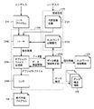
図12は、本発明の実施の形態に係るサポート装置200による実行可能プログラムの生成処理の手順を示すフローチャートである。図12に示す処理手順は、サポート装置200のCPU201がプログラミングアプリケーション250を実行することによって実現される。
FIG. 12 is a flowchart showing a procedure for generating an executable program by the
図12を参照して、サポート装置200のCPU201は、ユーザが作成した変数設定272およびソースプログラム274を受け付ける(ステップS100)。CPU201は、変数設定272を参照して、受け付けたソースプログラム274についての構文解析を行い、使用されている内部変数を抽出する(ステップS102)。
Referring to FIG. 12,
続いて、CPU201は、ステップS102において抽出した内部変数のうち最初の内部変数を処理対象に選択する(ステップS104)。そして、CPU201は、処理対象に選択した内部変数に対してネットワーク公開属性が設定されているか否かを判断する(ステップS106)。
Subsequently, the
ネットワーク公開属性が設定されていない場合(ステップS106においてNOの場合)には、CPU201は、処理対象の内部変数に対して通常のデータ構造で読出し/書込みされるようにオブジェクトファイルを生成する(ステップS108)。そして、処理は、ステップS116へ進む。
If the network public attribute is not set (NO in step S106), the
これに対して、ネットワーク公開属性が設定されている場合(ステップS106においてYESの場合)には、CPU201は、処理対象に選択した内部変数のネットワーク公開属性に基づいて、接続先のPLCの種別情報を取得する(ステップS110)。続いて、CPU201は、取得した種別情報に対応するデータ構造情報を取得し、さらに、取得したデータ構造情報における処理対象の内部変数のデータ型に対応するデータ構造を特定する(ステップS112)。CPU201は、処理対象の内部変数に対して特定したデータ構造で読出し/書込みされるようにオブジェクトファイルを生成する(ステップS114)。そして、処理は、ステップS116へ進む。
On the other hand, if the network public attribute is set (YES in step S106), the
CPU201は、ステップS102において抽出した内部変数のすべてについての処理が完了したか否かを判断する(ステップS116)。ステップS102において抽出した内部変数のすべてについての処理は完了していない場合(ステップS116においてNOの場合)には、CPU201は、ステップS102において抽出した内部変数のうち未処理のいずれかの内部変数を処理対象に選択し(ステップS118)、ステップS106以下の処理を繰り返す。
The
これに対して、ステップS102において抽出した内部変数のすべてについての処理が完了している場合(ステップS116においてYESの場合)には、CPU201は、生成されたオブジェクトファイルを連結して実行可能プログラムを生成する(ステップS120)。そして、処理は終了する。
On the other hand, if the processing for all the internal variables extracted in step S102 has been completed (YES in step S116), the
<I.変形例>
上述の実施の形態においては、ネットワーク変数を遣り取りする相手先のPLCの種別をIPアドレスなどによって特定する方法について例示したが、これに限られず、任意の方法を採用することができる。
<I. Modification>
In the above-described embodiment, the method of specifying the PLC type of the partner to which the network variable is exchanged by the IP address or the like is exemplified, but the present invention is not limited to this, and any method can be adopted.
例えば、相手先のPLCの機種などが既知である場合には、ユーザがネットワーク公開属性を設定する際に、そのPLCの種別を直接的に設定してもよい。このような構成を採用した場合には、図11に示すネットワーク接続情報276が不要になる。
For example, if the PLC model of the other party is known, the PLC type may be set directly when the user sets the network public attribute. When such a configuration is adopted, the
さらに、相手先のPLCの機種における対応するデータ構造が既知である場合には、ユーザがネットワーク公開属性を設定する際に、そのPLCにおけるデータ構造を直接的に設定してもよい。このような構成を採用した場合には、図11に示すデータ構造情報278が不要になる。
Furthermore, when the data structure corresponding to the PLC model of the other party is known, when the user sets the network public attribute, the data structure in the PLC may be set directly. When such a configuration is adopted, the
また、上述の実施の形態においては、メインメモリ104に格納されるそれぞれの変数のデータ構造を適合化する構成について例示したが、ネットワークコントローラ140のバッファメモリ146に格納されるそれぞれの変数のデータ構造を適合化してもよい。この場合には、メインメモリ104に格納される変数は、PLC1の本来のデータ構造で格納されており、他のPLCから受信されてバッファメモリ146に一次的に格納されたデータが対応する変数値としてメインメモリ104に転送される際にデータ構造の変換処理(適合化処理)が行われてもよい。また、他のPLCへ送信されるためにメインメモリ104からバッファメモリ146へデータが転送される際にデータ構造の変換処理(適合化処理)が行われてもよい。
In the above-described embodiment, the configuration for adapting the data structure of each variable stored in the
<J.利点>
本実施の形態に係るサポート装置200は、PLC間で変数を指定してデータが遣り取りされる場合において、相手先のPLCが扱うデータ構造が一致してないくとも、ネットワークを介してデータをより容易にデータを遣り取りできる。
<J. Advantage>
今回開示された実施の形態はすべての点で例示であって制限的なものではないと考えられるべきである。本発明の範囲は、上記した説明ではなく、特許請求の範囲によって示され、特許請求の範囲と均等の意味および範囲内でのすべての変更が含まれることが意図される。 The embodiment disclosed this time should be considered as illustrative in all points and not restrictive. The scope of the present invention is defined by the terms of the claims, rather than the description above, and is intended to include any modifications within the scope and meaning equivalent to the terms of the claims.
6 検出センサー、7 リレー、10 処理ユニット、11 システムバス、12 電源ユニット、13 接続ケーブル、14 ユニット、100 プロセッサ、102 チップセット、104 メインメモリ、106 不揮発性メモリ、108 システムタイマ、110 USBコネクタ、120 システムバスコントローラ、122 DMA制御回路、124 システムバス制御回路、126,146 バッファメモリ、130 システムバスコネクタ、140 ネットワークコントローラ、144 ネットワーク制御回路、160 スケジューラ、170 ユーザ定義アプリケーション、172 入力処理モジュール、174 出力処理モジュール、176 通信処理モジュール、178 システムモジュール、180 命令実行モジュール、184 メモリマネジャー、186 データ構造変換モジュール、190 リアルタイムOS、200 サポート装置、201 CPU、202 ROM、203 RAM、204 ハードディスク(HDD)、205 キーボード、206 マウス、207 モニタ、208 CD−ROMドライブ、240 OS、250 プログラミングアプリケーション、252,282 エディタ、254 コンパイラ、256 デバッガ、258 GUIモジュール、260 シミュレータ、270,290 データ格納部、274 ソースプログラム、276 ネットワーク接続情報、278 データ構造情報、280 ネットワーク設定アプリケーション、284 コンフィグレータ、296 コネクション設定、300 CD−ROM、2542 パーサ、2544 オブジェクトファイル生成部、2546 データ構造特定部、2548 リンカ、2721 内部変数定義、2722 ネットワーク公開属性、NW ネットワーク、SYS システム。 6 detection sensor, 7 relay, 10 processing unit, 11 system bus, 12 power supply unit, 13 connection cable, 14 unit, 100 processor, 102 chipset, 104 main memory, 106 non-volatile memory, 108 system timer, 110 USB connector, 120 system bus controller, 122 DMA control circuit, 124 system bus control circuit, 126, 146 buffer memory, 130 system bus connector, 140 network controller, 144 network control circuit, 160 scheduler, 170 user-defined application, 172 input processing module, 174 Output processing module, 176 communication processing module, 178 system module, 180 instruction execution module, 184 memory Remanager, 186 Data structure conversion module, 190 Real-time OS, 200 Support device, 201 CPU, 202 ROM, 203 RAM, 204 Hard disk (HDD), 205 Keyboard, 206 Mouse, 207 Monitor, 208 CD-ROM drive, 240 OS, 250 programming application, 252, 282 editor, 254 compiler, 256 debugger, 258 GUI module, 260 simulator, 270, 290 data storage unit, 274 source program, 276 network connection information, 278 data structure information, 280 network setting application, 284 configurator 296 connection setting, 300 CD-ROM, 2542 parser, 2544 of E transfected file generation unit, 2546 data structure specifying unit 2548 linker 2721 internal variable definitions, 2722 network public attribute, NW network, SYS system.
Claims (7)
前記第1のプログラマブルロジックコントローラで扱われるデータ別に変数を定義する情報を受け付ける第1の入力手段と、
前記第1のプログラマブルロジックコントローラで実行される処理を、定義された変数を用いて記述したソースプログラムを受け付ける第2の入力手段と、
前記第1のプログラマブルロジックコントローラで扱われる第1のデータを示す第1の変数と、前記第1のプログラマブルロジックコントローラとネットワーク接続された第2のプログラマブルロジックコントローラで扱われる第2のデータを示す第2の変数とがネットワークを介して対応付けられている場合に、前記第1の変数に関連付けて前記第2のプログラマブルロジックコントローラの種別を特定する情報を受け付ける第3の入力手段と、
前記変数を定義する情報および前記ソースプログラムを用いて前記実行可能プログラムを生成する生成手段とを備え、前記生成手段は、前記第2のプログラマブルロジックコントローラの種別に応じて、前記第1の変数に対応してメモリ上に確保される前記第1のデータのデータ構造を適合化する、サポート装置。 A support device for generating an executable program to be executed by a first programmable logic controller including a processor, a memory, and a network interface,
First input means for receiving information defining variables for each data handled by the first programmable logic controller;
Second input means for receiving a source program describing processing executed by the first programmable logic controller using a defined variable;
A first variable indicating first data handled by the first programmable logic controller, and a second variable indicating second data handled by a second programmable logic controller connected to the first programmable logic controller via a network. A second input unit that receives information specifying the type of the second programmable logic controller in association with the first variable when the second variable is associated with the second variable;
Generating means for generating the executable program using the information defining the variable and the source program, wherein the generating means sets the first variable according to a type of the second programmable logic controller. A support device for adapting a data structure of the first data correspondingly secured in the memory.
前記生成手段は、前記第2のプログラマブルロジックコントローラにおける、第1のデータの型に対応するデータ構造に従って、前記第1のデータを前記メモリに格納するための命令を含む実行可能プログラムを生成する、請求項1に記載のサポート装置。 The information defining the variable includes information defining the type of data corresponding to the variable,
The generating means generates an executable program including an instruction for storing the first data in the memory according to a data structure corresponding to a type of the first data in the second programmable logic controller. The support device according to claim 1.
前記第1のプログラマブルロジックコントローラで扱われるデータ別に変数を定義する情報を受け付ける第1の入力手段と、
前記第1のプログラマブルロジックコントローラで実行される処理を、定義された変数を用いて記述したソースプログラムを受け付ける第2の入力手段と、
前記第1のプログラマブルロジックコントローラで扱われる第1のデータを示す第1の変数と、前記第1のプログラマブルロジックコントローラとネットワーク接続された第2のプログラマブルロジックコントローラで扱われる第2のデータを示す第2の変数とがネットワークを介して対応付けられている場合に、前記第1の変数に関連付けて前記第2の
プログラマブルロジックコントローラの種別を特定する情報を受け付ける第3の入力手段と、
前記変数を定義する情報および前記ソースプログラムを用いて前記実行可能プログラムを生成する生成手段として機能させ、前記生成手段は、前記第2のプログラマブルロジックコントローラの種別に応じて、前記第1の変数に対応してメモリ上に確保される前記第1のデータのデータ構造を適合化する、サポートプログラム。 A support program for generating an executable program executed by a first programmable logic controller including a processor, a memory, and a network interface, the support program comprising:
First input means for receiving information defining variables for each data handled by the first programmable logic controller;
Second input means for receiving a source program describing processing executed by the first programmable logic controller using a defined variable;
A first variable indicating first data handled by the first programmable logic controller, and a second variable indicating second data handled by a second programmable logic controller connected to the first programmable logic controller via a network. A second input unit that receives information specifying the type of the second programmable logic controller in association with the first variable when the second variable is associated with the second variable;
Using the information defining the variable and the source program to function as a generating unit that generates the executable program, the generating unit sets the first variable according to the type of the second programmable logic controller. A support program for adapting the data structure of the first data correspondingly secured in the memory.
Priority Applications (5)
| Application Number | Priority Date | Filing Date | Title |
|---|---|---|---|
| JP2012019785A JP5942446B2 (en) | 2012-02-01 | 2012-02-01 | Support device and support program |
| US14/375,930 US9746845B2 (en) | 2012-02-01 | 2013-01-10 | Support device, recording medium, and method for facilitating data exchange between different types of progrrammable logic controllers |
| CN201380006466.6A CN104067186B (en) | 2012-02-01 | 2013-01-10 | Assisting system, record have record medium and the method for generation executable program of support program |
| PCT/JP2013/050285 WO2013114926A1 (en) | 2012-02-01 | 2013-01-10 | Support device, recording medium having support program recorded thereon, and method for generating executable program |
| EP13743088.0A EP2811353B1 (en) | 2012-02-01 | 2013-01-10 | Support device, recording medium having support program recorded thereon, and method for generating executable program |
Applications Claiming Priority (1)
| Application Number | Priority Date | Filing Date | Title |
|---|---|---|---|
| JP2012019785A JP5942446B2 (en) | 2012-02-01 | 2012-02-01 | Support device and support program |
Publications (2)
| Publication Number | Publication Date |
|---|---|
| JP2013161106A JP2013161106A (en) | 2013-08-19 |
| JP5942446B2 true JP5942446B2 (en) | 2016-06-29 |
Family
ID=48904970
Family Applications (1)
| Application Number | Title | Priority Date | Filing Date |
|---|---|---|---|
| JP2012019785A Active JP5942446B2 (en) | 2012-02-01 | 2012-02-01 | Support device and support program |
Country Status (5)
| Country | Link |
|---|---|
| US (1) | US9746845B2 (en) |
| EP (1) | EP2811353B1 (en) |
| JP (1) | JP5942446B2 (en) |
| CN (1) | CN104067186B (en) |
| WO (1) | WO2013114926A1 (en) |
Families Citing this family (27)
| Publication number | Priority date | Publication date | Assignee | Title |
|---|---|---|---|---|
| WO2014038334A1 (en) * | 2012-09-05 | 2014-03-13 | 三菱電機株式会社 | Input/output response control setting device |
| WO2014112990A1 (en) * | 2013-01-16 | 2014-07-24 | Siemens Aktiengesellschaft | Automated input simulation for simulated programmable logic controller |
| JP6150953B2 (en) * | 2015-06-01 | 2017-06-21 | 三菱電機株式会社 | Debugging device, debugging method, and debugging program |
| KR101870492B1 (en) | 2015-06-22 | 2018-06-22 | 엘에스산전 주식회사 | Programmable Logic Controller System |
| KR102004456B1 (en) * | 2016-08-12 | 2019-07-30 | 주식회사 유디엠텍 | Apparatus and method for transforming PLC control program into structured data |
| WO2018030831A1 (en) * | 2016-08-12 | 2018-02-15 | 주식회사 유디엠텍 | Apparatus and method for converting plc control program into structured data |
| JP6532610B2 (en) * | 2016-08-30 | 2019-06-19 | 三菱電機株式会社 | Program editing apparatus, program editing method and program editing program |
| JP6813381B2 (en) * | 2017-02-06 | 2021-01-13 | 株式会社日立産機システム | Programmable logic controller |
| JP2019049854A (en) * | 2017-09-10 | 2019-03-28 | 益満 大 | Program and information processing system |
| JP6954191B2 (en) * | 2018-03-12 | 2021-10-27 | オムロン株式会社 | Control systems, development support equipment, and development support programs |
| JP7268287B2 (en) * | 2018-03-12 | 2023-05-08 | オムロン株式会社 | Control system, control method and control program |
| JP6891838B2 (en) * | 2018-03-15 | 2021-06-18 | オムロン株式会社 | Development support equipment, development support methods, and development support programs |
| JP7124389B2 (en) * | 2018-03-30 | 2022-08-24 | セイコーエプソン株式会社 | Controllers, robots and robotic systems |
| JP2019179476A (en) * | 2018-03-30 | 2019-10-17 | オムロン株式会社 | Support apparatus, support program, and setting method |
| JP6915583B2 (en) * | 2018-04-13 | 2021-08-04 | オムロン株式会社 | Safety control system and control method in safety control system |
| JP7003842B2 (en) * | 2018-05-31 | 2022-01-21 | オムロン株式会社 | Support equipment and support programs |
| JP7067286B2 (en) * | 2018-06-06 | 2022-05-16 | オムロン株式会社 | Control system, control system control method, and control system program |
| JP7115195B2 (en) * | 2018-09-28 | 2022-08-09 | オムロン株式会社 | Control system, support equipment, support program |
| JP7172397B2 (en) * | 2018-10-02 | 2022-11-16 | オムロン株式会社 | Control systems, support equipment and programs |
| JP2020057332A (en) * | 2018-10-04 | 2020-04-09 | オムロン株式会社 | Program generation device, control method for program generation device, control program, and recording medium |
| JP7024679B2 (en) * | 2018-10-05 | 2022-02-24 | オムロン株式会社 | Development support programs, development support devices, and development support methods |
| JP7040484B2 (en) * | 2019-03-14 | 2022-03-23 | オムロン株式会社 | Control systems, support devices, and support programs |
| JP7375360B2 (en) | 2019-08-02 | 2023-11-08 | オムロン株式会社 | Network system, information processing device, and information processing method |
| JP7404748B2 (en) * | 2019-10-03 | 2023-12-26 | オムロン株式会社 | Program development device and program for realizing the program development device |
| US20240085879A1 (en) * | 2021-01-22 | 2024-03-14 | Nec Corporation | Program analysis assistance apparatus, program analysis assistance method, and computer readable recording medium |
| CN114237144B (en) * | 2021-11-22 | 2024-04-02 | 上海交通大学宁波人工智能研究院 | System and method for PLC security and credibility based on embedded type |
| WO2023152835A1 (en) * | 2022-02-09 | 2023-08-17 | ファナック株式会社 | Control device for robot that communicates with programmable logic controller |
Family Cites Families (15)
| Publication number | Priority date | Publication date | Assignee | Title |
|---|---|---|---|---|
| JP2625565B2 (en) * | 1990-05-23 | 1997-07-02 | シャープ株式会社 | Communication network programmer |
| JP3423626B2 (en) * | 1998-10-30 | 2003-07-07 | 株式会社デジタル | Control host computer and recording medium on which the program is recorded |
| JP3932817B2 (en) | 2001-03-14 | 2007-06-20 | オムロン株式会社 | Control system |
| JP2004038876A (en) * | 2002-07-08 | 2004-02-05 | Hitachi Ltd | Data format conversion method and device for program and the like, and controller management system using the data format conversion device |
| US7895589B2 (en) * | 2003-02-26 | 2011-02-22 | International Business Machines Corporation | Dynamic data-driven application integration adapters |
| EP1612630B1 (en) * | 2004-06-29 | 2015-02-25 | Rockwell Automation Technologies, Inc. | Extensible data transformation system |
| US7689727B2 (en) * | 2006-01-24 | 2010-03-30 | National Instruments Corporation | System and method for automatically updating the memory map of a programmable controller to customized hardware |
| TWI339818B (en) * | 2006-08-08 | 2011-04-01 | Siemens Energy & Automat | Devices, systems, and methods for initializing a plc module |
| EP1895740B2 (en) * | 2006-08-28 | 2023-07-26 | Rockwell Automation Technologies, Inc. | Structured data support using metadata and a type library in a control system |
| JP2008217160A (en) * | 2007-02-28 | 2008-09-18 | Nippon Telegr & Teleph Corp <Ntt> | Sensing data conversion system, data conversion device and data conversion method |
| US8407716B2 (en) * | 2007-05-31 | 2013-03-26 | Fisher-Rosemount Systems, Inc. | Apparatus and methods to access information associated with a process control system |
| CN101393445A (en) * | 2008-10-31 | 2009-03-25 | 中冶长天国际工程有限责任公司 | Method for implementing data transmission between PLC of different brands |
| JP5444112B2 (en) * | 2010-04-30 | 2014-03-19 | 株式会社東芝 | Plant control system and program relocate method |
| CN102045334A (en) * | 2010-09-27 | 2011-05-04 | 北京泰豪智能工程有限公司 | Protocol conversion method and device |
| CN102073297A (en) * | 2011-01-12 | 2011-05-25 | 广州蓄能水电厂 | Large-scale data transmission method between programmable controllers of different types |
-
2012
- 2012-02-01 JP JP2012019785A patent/JP5942446B2/en active Active
-
2013
- 2013-01-10 EP EP13743088.0A patent/EP2811353B1/en active Active
- 2013-01-10 WO PCT/JP2013/050285 patent/WO2013114926A1/en active Application Filing
- 2013-01-10 US US14/375,930 patent/US9746845B2/en active Active
- 2013-01-10 CN CN201380006466.6A patent/CN104067186B/en active Active
Also Published As
| Publication number | Publication date |
|---|---|
| US20150025656A1 (en) | 2015-01-22 |
| CN104067186B (en) | 2016-08-24 |
| EP2811353A1 (en) | 2014-12-10 |
| EP2811353A4 (en) | 2015-11-18 |
| WO2013114926A1 (en) | 2013-08-08 |
| JP2013161106A (en) | 2013-08-19 |
| EP2811353B1 (en) | 2017-08-16 |
| CN104067186A (en) | 2014-09-24 |
| US9746845B2 (en) | 2017-08-29 |
Similar Documents
| Publication | Publication Date | Title |
|---|---|---|
| JP5942446B2 (en) | Support device and support program | |
| US10977014B2 (en) | Web-based programming environment for embedded devices | |
| WO2023140299A1 (en) | Verification system, and verification method | |
| JP6550269B2 (en) | PROGRAM CREATION SUPPORT DEVICE, CONTROL METHOD, AND PROGRAM | |
| JP6362821B2 (en) | Control device, control method and instruction set | |
| WO2019230321A1 (en) | Support device and support program | |
| JP5808922B2 (en) | Air conditioner control interface device, air conditioner and air conditioner control system | |
| JP6135247B2 (en) | Information processing apparatus and information processing program | |
| WO2019171794A1 (en) | Support device and support program | |
| CN109937404B (en) | Method and system for real-time data exchange between program modules | |
| JP6484015B2 (en) | Programmable logic controller and control method thereof | |
| CN114938397A (en) | Kaitai-based high-efficiency protocol unpacking and packing method, system and readable storage medium | |
| JP2005092676A (en) | Programmable controller, unit, and method for editing parameter | |
| JP4776602B2 (en) | Programming device for controller, controller and controller management system | |
| CN110018959B (en) | Embedded application debugging method and system | |
| CN113703811B (en) | Method, device, equipment and storage medium for remotely downloading firmware by DSP | |
| Tran et al. | An open implementation of PROFIBUS DP | |
| WO2022049885A1 (en) | Control device | |
| Pamadi et al. | Getting Started With 1-Wire Bus Devices | |
| JP6303200B2 (en) | Circuit information creation device, circuit information creation system, and circuit information creation program | |
| CN114253240A (en) | Control method, device, equipment and storage medium for cloud industrial system equipment | |
| JP2022170173A (en) | Information processing device, method, and program | |
| CN114375428A (en) | Abstraction of PLC communications | |
| CN111309434A (en) | Method for parameterizing a field device | |
| TW201917600A (en) | Controlling method for integrating standard programming language script structure in virtual machine and computer program product |
Legal Events
| Date | Code | Title | Description |
|---|---|---|---|
| A621 | Written request for application examination |
Free format text: JAPANESE INTERMEDIATE CODE: A621 Effective date: 20150107 |
|
| A131 | Notification of reasons for refusal |
Free format text: JAPANESE INTERMEDIATE CODE: A131 Effective date: 20151215 |
|
| A521 | Request for written amendment filed |
Free format text: JAPANESE INTERMEDIATE CODE: A523 Effective date: 20160122 |
|
| TRDD | Decision of grant or rejection written | ||
| A01 | Written decision to grant a patent or to grant a registration (utility model) |
Free format text: JAPANESE INTERMEDIATE CODE: A01 Effective date: 20160426 |
|
| A61 | First payment of annual fees (during grant procedure) |
Free format text: JAPANESE INTERMEDIATE CODE: A61 Effective date: 20160509 |
|
| R150 | Certificate of patent or registration of utility model |
Ref document number: 5942446 Country of ref document: JP Free format text: JAPANESE INTERMEDIATE CODE: R150 |
|
| R250 | Receipt of annual fees |
Free format text: JAPANESE INTERMEDIATE CODE: R250 |
|
| R250 | Receipt of annual fees |
Free format text: JAPANESE INTERMEDIATE CODE: R250 |
|
| R250 | Receipt of annual fees |
Free format text: JAPANESE INTERMEDIATE CODE: R250 |