JP5939261B2 - Fixed member - Google Patents
Fixed member Download PDFInfo
- Publication number
- JP5939261B2 JP5939261B2 JP2013545160A JP2013545160A JP5939261B2 JP 5939261 B2 JP5939261 B2 JP 5939261B2 JP 2013545160 A JP2013545160 A JP 2013545160A JP 2013545160 A JP2013545160 A JP 2013545160A JP 5939261 B2 JP5939261 B2 JP 5939261B2
- Authority
- JP
- Japan
- Prior art keywords
- fixing member
- hydrophilic
- insert
- substrate
- member according
- Prior art date
- Legal status (The legal status is an assumption and is not a legal conclusion. Google has not performed a legal analysis and makes no representation as to the accuracy of the status listed.)
- Expired - Fee Related
Links
- 239000000853 adhesive Substances 0.000 claims description 72
- 230000001070 adhesive effect Effects 0.000 claims description 72
- 239000000758 substrate Substances 0.000 claims description 47
- 239000000463 material Substances 0.000 claims description 23
- 229910001369 Brass Inorganic materials 0.000 claims description 3
- 229920000742 Cotton Polymers 0.000 claims description 3
- 229910000831 Steel Inorganic materials 0.000 claims description 3
- 239000002390 adhesive tape Substances 0.000 claims description 3
- 239000010951 brass Substances 0.000 claims description 3
- 239000011248 coating agent Substances 0.000 claims description 3
- 238000000576 coating method Methods 0.000 claims description 3
- 239000002131 composite material Substances 0.000 claims description 3
- 239000004744 fabric Substances 0.000 claims description 3
- 239000000835 fiber Substances 0.000 claims description 3
- 229920005573 silicon-containing polymer Polymers 0.000 claims description 3
- 239000010959 steel Substances 0.000 claims description 3
- 238000001723 curing Methods 0.000 description 13
- 239000010410 layer Substances 0.000 description 7
- 239000007789 gas Substances 0.000 description 6
- 239000000203 mixture Substances 0.000 description 6
- 239000007788 liquid Substances 0.000 description 5
- 239000003570 air Substances 0.000 description 4
- 239000012080 ambient air Substances 0.000 description 4
- 239000012298 atmosphere Substances 0.000 description 4
- 238000005538 encapsulation Methods 0.000 description 3
- 238000002156 mixing Methods 0.000 description 3
- 239000012790 adhesive layer Substances 0.000 description 2
- 238000000034 method Methods 0.000 description 2
- BLRPTPMANUNPDV-UHFFFAOYSA-N Silane Chemical compound [SiH4] BLRPTPMANUNPDV-UHFFFAOYSA-N 0.000 description 1
- 229910052782 aluminium Inorganic materials 0.000 description 1
- XAGFODPZIPBFFR-UHFFFAOYSA-N aluminium Chemical compound [Al] XAGFODPZIPBFFR-UHFFFAOYSA-N 0.000 description 1
- QVGXLLKOCUKJST-UHFFFAOYSA-N atomic oxygen Chemical compound [O] QVGXLLKOCUKJST-UHFFFAOYSA-N 0.000 description 1
- 239000003795 chemical substances by application Substances 0.000 description 1
- 230000001419 dependent effect Effects 0.000 description 1
- 239000004615 ingredient Substances 0.000 description 1
- 230000002401 inhibitory effect Effects 0.000 description 1
- 238000009434 installation Methods 0.000 description 1
- 230000002045 lasting effect Effects 0.000 description 1
- 238000012423 maintenance Methods 0.000 description 1
- 230000014759 maintenance of location Effects 0.000 description 1
- 239000004579 marble Substances 0.000 description 1
- 239000002184 metal Substances 0.000 description 1
- 229910052751 metal Inorganic materials 0.000 description 1
- 239000007769 metal material Substances 0.000 description 1
- 238000013008 moisture curing Methods 0.000 description 1
- 239000001301 oxygen Substances 0.000 description 1
- 229910052760 oxygen Inorganic materials 0.000 description 1
- 239000011148 porous material Substances 0.000 description 1
- 229910000077 silane Inorganic materials 0.000 description 1
- 239000011343 solid material Substances 0.000 description 1
Images


Classifications
-
- F—MECHANICAL ENGINEERING; LIGHTING; HEATING; WEAPONS; BLASTING
- F16—ENGINEERING ELEMENTS AND UNITS; GENERAL MEASURES FOR PRODUCING AND MAINTAINING EFFECTIVE FUNCTIONING OF MACHINES OR INSTALLATIONS; THERMAL INSULATION IN GENERAL
- F16B—DEVICES FOR FASTENING OR SECURING CONSTRUCTIONAL ELEMENTS OR MACHINE PARTS TOGETHER, e.g. NAILS, BOLTS, CIRCLIPS, CLAMPS, CLIPS OR WEDGES; JOINTS OR JOINTING
- F16B11/00—Connecting constructional elements or machine parts by sticking or pressing them together, e.g. cold pressure welding
- F16B11/006—Connecting constructional elements or machine parts by sticking or pressing them together, e.g. cold pressure welding by gluing
-
- F—MECHANICAL ENGINEERING; LIGHTING; HEATING; WEAPONS; BLASTING
- F16—ENGINEERING ELEMENTS AND UNITS; GENERAL MEASURES FOR PRODUCING AND MAINTAINING EFFECTIVE FUNCTIONING OF MACHINES OR INSTALLATIONS; THERMAL INSULATION IN GENERAL
- F16B—DEVICES FOR FASTENING OR SECURING CONSTRUCTIONAL ELEMENTS OR MACHINE PARTS TOGETHER, e.g. NAILS, BOLTS, CIRCLIPS, CLAMPS, CLIPS OR WEDGES; JOINTS OR JOINTING
- F16B47/00—Suction cups for attaching purposes; Equivalent means using adhesives
- F16B47/003—Suction cups for attaching purposes; Equivalent means using adhesives using adhesives for attaching purposes
-
- F—MECHANICAL ENGINEERING; LIGHTING; HEATING; WEAPONS; BLASTING
- F16—ENGINEERING ELEMENTS AND UNITS; GENERAL MEASURES FOR PRODUCING AND MAINTAINING EFFECTIVE FUNCTIONING OF MACHINES OR INSTALLATIONS; THERMAL INSULATION IN GENERAL
- F16C—SHAFTS; FLEXIBLE SHAFTS; ELEMENTS OR CRANKSHAFT MECHANISMS; ROTARY BODIES OTHER THAN GEARING ELEMENTS; BEARINGS
- F16C11/00—Pivots; Pivotal connections
- F16C11/04—Pivotal connections
-
- Y—GENERAL TAGGING OF NEW TECHNOLOGICAL DEVELOPMENTS; GENERAL TAGGING OF CROSS-SECTIONAL TECHNOLOGIES SPANNING OVER SEVERAL SECTIONS OF THE IPC; TECHNICAL SUBJECTS COVERED BY FORMER USPC CROSS-REFERENCE ART COLLECTIONS [XRACs] AND DIGESTS
- Y10—TECHNICAL SUBJECTS COVERED BY FORMER USPC
- Y10T—TECHNICAL SUBJECTS COVERED BY FORMER US CLASSIFICATION
- Y10T403/00—Joints and connections
- Y10T403/32—Articulated members
- Y10T403/32114—Articulated members including static joint
-
- Y—GENERAL TAGGING OF NEW TECHNOLOGICAL DEVELOPMENTS; GENERAL TAGGING OF CROSS-SECTIONAL TECHNOLOGIES SPANNING OVER SEVERAL SECTIONS OF THE IPC; TECHNICAL SUBJECTS COVERED BY FORMER USPC CROSS-REFERENCE ART COLLECTIONS [XRACs] AND DIGESTS
- Y10—TECHNICAL SUBJECTS COVERED BY FORMER USPC
- Y10T—TECHNICAL SUBJECTS COVERED BY FORMER US CLASSIFICATION
- Y10T403/00—Joints and connections
- Y10T403/47—Molded joint
Description
本発明は、請求項1の上位概念部に記載の固定部材に関する。
The present invention relates to a fixing member described in the superordinate conceptual part of
取付けシステムの構成部分としてのこのような固定部材は、国際公開第03/036106号から公知である。 Such a fixing member as a component of the mounting system is known from WO 03/036106.
この取付けシステムは、タオル掛け、棚、照明器具または類似の装備品のような対象物を、特にタイル、大理石板または類似の壁化粧板を備えた部屋の壁、天井または類似の面に対して固定的に取り付けるために働く。取付けシステムは、種々の固定部材および付着・接合材から成っている。付着・接合材は、好気性接着剤(aeroben Klebstoff)から形成されていてよく、この場合、固定部材は使用目的に応じてその形状を適合され得る。このようなシステムで不都合なのは、接着剤の、12時間に及び得る極めて長い硬化時間であり、これによってこのシステムの取付け易さは著しく損なわれている。周辺雰囲気が冷たく乾燥している場合、硬化は特に大幅に妨げられるおそれがある。 This mounting system allows objects such as towel racks, shelves, luminaires or similar equipment, especially against room walls, ceilings or similar surfaces with tiles, marble boards or similar wall facings. Works for fixed mounting. The mounting system consists of various fixing members and adhesive / bonding materials. The adhesion / bonding material may be formed of an aerobic adhesive (aeroben Klebstoff). In this case, the fixing member may be adapted in shape according to the purpose of use. Disadvantageous with such a system is the extremely long curing time of the adhesive, which can be as long as 12 hours, which significantly impairs the ease of installation of the system. If the ambient atmosphere is cold and dry, curing can be particularly hindered.
固定部材は、対象物を保持するためのエレメントの収容に役立ち、かつ基体を備えている。基体は、壁に向けられた背面に、切欠きと、該切欠きに通じる充填開口とを有している。この充填開口を介して、付着材もしくは接合材が固定部材と壁との間に導入される。 The fixing member serves to accommodate an element for holding an object and includes a base. The substrate has a notch and a filling opening leading to the notch on the back side facing the wall. An adhesive or bonding material is introduced between the fixing member and the wall through the filling opening.
基体の、壁に向けられた背面は、少なくとも部分領域において、液体およびガス透過性であるので、切欠き内に位置する付着・接合材が硬化する際に発生するガスが抜け出る、もしくは揮発した接合剤が発散することができると同時に、周辺空気がこの付着・接合材に到達する。これによって、付着・接合材は硬化することができ、壁に対する固定部材の安定した、負荷に耐える位置固定をもたらす。 The back of the substrate facing the wall is permeable to liquid and gas at least in a partial area, so that the gas generated when the adhesion / bonding material located in the notch is cured escapes or volatilizes. At the same time as the agent can diverge, the ambient air reaches this adhesion / bonding material. As a result, the adhering / bonding material can be hardened, and the fixing member can be fixed to the wall in a stable and load-resistant position.
しかしこの構成では、十分な硬化を確保するために、付着・接合材は、常に基体のガスおよび液体透過性の壁を介して周辺空気に接触しなければならないという不都合が生じる。このことは、固定部材の構造的な造形可能性を不都合に強く制限する。 However, in this configuration, in order to ensure sufficient curing, there arises a disadvantage that the adhesion / bonding material must always come into contact with the surrounding air through the gas and liquid permeable walls of the substrate. This inconveniently restricts the structural modeling possibilities of the fixing member.
国際公開第2009/156013号から公知の固定手段は、好気性接着剤と親水性の素材との混合物から成っている。好気性接着剤に親水性の素材を添加することにより固定手段を形成する混合物が生じる。この混合物は、表面から硬化させるために湿気のある周辺空気に表面接触する必要がない。むしろ、混合物内に存在する、好気性接着剤に混ぜられた親水性の素材は、湿気を含む周辺空気との外部接触がもはや与えられていない場合にも、混合物に含まれる好気性接着剤を内部から硬化することができるようにする。硬化のために必要な湿気もしくは必要な酸素は、親水性の素材自体のなかに存在している。なぜならばこの親水性の素材は、その親水特性に基づいて、固定手段を形成する混合物中の好気性接着剤の硬化のために必要である十分な湿気を含んでいるからである。 The fixing means known from WO 2009/156013 consist of a mixture of an aerobic adhesive and a hydrophilic material. Addition of a hydrophilic material to the aerobic adhesive results in a mixture that forms the securing means. This mixture need not be in surface contact with humid ambient air in order to cure from the surface. Rather, the hydrophilic material mixed in the aerobic adhesive present in the mixture will remove the aerobic adhesive contained in the mixture, even when external contact with ambient air containing moisture is no longer provided. Allow curing from the inside. Moisture or oxygen necessary for curing is present in the hydrophilic material itself. This is because the hydrophilic material contains sufficient moisture necessary for curing of the aerobic adhesive in the mixture forming the fixing means, based on its hydrophilic properties.
このように形成された固定手段によって、該固定手段の層を対象物と基礎部との間に導入することによって、対象物を基礎部に簡単に位置固定することができる。 By introducing the fixing means layer between the object and the base portion by the fixing means formed in this way, the position of the object can be easily fixed to the base portion.
この固定手段を使用するためには、まず固定手段の成分が使用の直前に混合されることが重要である。 In order to use this fixing means, it is important that the components of the fixing means are first mixed immediately before use.
このためには、取付けキットが提供される。この取付けキットは、好気性接着剤と、親水性の素材を別個に支持するための2つの収容部を有している。これらの収容部から、所望の量の成分が、混合により固定手段を形成するために取り出され得る。混合はスパチュラにより行われる。 For this, a mounting kit is provided. This mounting kit has two housing parts for separately supporting an aerobic adhesive and a hydrophilic material. From these receptacles, a desired amount of ingredients can be removed to form the fixing means by mixing. Mixing is performed with a spatula.
次いで固定手段の層が対象物に被着され、対象物は次いで基礎部において、固定手段の層を基礎部に対して押圧することにより位置固定される。この層内では、好気性接着剤が親水性の素材に含まれる湿気により硬化する。 The layer of fixing means is then applied to the object and the object is then fixed in place at the base by pressing the layer of fixing means against the base. In this layer, the aerobic adhesive is cured by moisture contained in the hydrophilic material.
本発明の根底を成す課題は、冒頭で述べた形式の固定部材を改良して、高い機能性において簡単に取扱い可能かつ臨機応変に使用可能にすることである。 The problem underlying the present invention is to improve a fixing member of the type mentioned at the outset so that it can be easily handled and used flexibly with high functionality.
上記課題を解決するために、請求項1の特徴部に記載の特徴が設けられている。本発明の有利な態様および好適な変化形は、従属請求項に記載されている。
In order to solve the above problems, the features described in the characterizing portion of
本発明による固定部材は、基体と、ガスおよび液体非透過性の材料とから成っている。固定部材は対象物を収容する手段を有していて、かつ接着剤により載着面に位置固定可能である。基体の、載着面に面した内面には、親水性のインサートが被着されている。この親水性のインサートには、調量されて(dosiert)湿気が供給され、かつこの親水性のインサートには好気性接着剤が被着可能である。好気性接着剤は親水性のインサートと共に、載着面と基体とにより閉じられた中空室内にガス密かつ液密に封入されている。 The fixing member according to the present invention comprises a base and a gas and liquid impermeable material. The fixing member has means for accommodating the object and can be fixed to the mounting surface by an adhesive. A hydrophilic insert is attached to the inner surface of the substrate facing the mounting surface. The hydrophilic insert is dosed with moisture, and an aerobic adhesive can be applied to the hydrophilic insert. The aerobic adhesive is sealed in a gas-tight and liquid-tight manner together with a hydrophilic insert in a hollow chamber closed by the mounting surface and the substrate.
本発明による固定部材により、対象物が載着面に確実に固定され得る。この場合、この確実な固定のために、ねじ等を用いた構造的な係合部を載着面または対象物に取り付ける必要はない。 With the fixing member according to the present invention, the object can be reliably fixed to the mounting surface. In this case, there is no need to attach a structural engagement portion using screws or the like to the mounting surface or the object for this secure fixing.
本発明の重要な観点は、固定部材における好気性接着剤と親水性のインサートとの協働にある。調量された適量の湿気を得る親水性のインサートと好気性接着剤との接触により、好気性接着剤の全容量が硬化し、この場合に、硬化のために周辺空気と接触することは不要である。 An important aspect of the present invention lies in the cooperation of the aerobic adhesive and the hydrophilic insert in the fixing member. The contact between the aerobic adhesive and a hydrophilic insert that delivers a metered amount of moisture cures the entire volume of the aerobic adhesive, in which case it is not necessary to contact ambient air for curing It is.
親水性のインサートと相互作用する好気性接着剤により、対象物の、耐性のある確実な、特に迅速に提供可能な固定が達成され、しかもねじおよび類似の機械的な固定手段はいずれも使用されない。 Aerobic adhesive that interacts with the hydrophilic insert achieves a secure, particularly fast-provokable fixation of the object, and no screws and similar mechanical fastening means are used .
特に国際公開第2009/156013号から公知の固定手段に対する重要な利点は、好気性接着剤と、親水性の素材との混合がもはや不要であることにある。むしろ、親水性のインサートに対する好気性接着剤の機械的な接触だけで十分であり、この機械的な接触は、この親水性のインサートへの好気性接着剤の塗布時に与えられて、これによって載着面と固定部材の基体と間に好気性接着剤を完全にガス密かつ液密に封入した場合に、好気性接着剤の完全な硬化を保証することができる。したがって、親水性の素材と好気性接着剤との時間のかかる混合は省略され、これにより、固定部材の高い取付け易さが与えられている。 An important advantage over the fastening means known from WO 2009/156013 in particular is that it is no longer necessary to mix aerobic adhesives with hydrophilic materials. Rather, mechanical contact of the aerobic adhesive to the hydrophilic insert is sufficient, and this mechanical contact is provided during application of the aerobic adhesive to the hydrophilic insert and is thereby mounted. When the aerobic adhesive is completely gas-tight and liquid-tightly sealed between the landing surface and the base of the fixing member, complete curing of the aerobic adhesive can be ensured. Therefore, time-consuming mixing of the hydrophilic material and the aerobic adhesive is omitted, which gives high attachment ease of the fixing member.
この組付け易さは、親水性のインサートが接着材により、または機械的な取付け部分によって基体の内面に固定されていることにより高められる。 This ease of assembly is enhanced by the hydrophilic insert being fixed to the inner surface of the substrate by an adhesive or by a mechanical attachment.
したがって、基体と、親水性のインサートとは、載着面に固定部材を取り付けるために単に好気性接着剤を供給されるだけでよい構造ユニットを形成する。 Thus, the substrate and the hydrophilic insert form a structural unit that may simply be supplied with an aerobic adhesive to attach the fixing member to the mounting surface.
本発明の別の重要な利点は、好気性接着剤と親水性のインサートとが、載着面と基体との間の中空室にガス密かつ液密に封入されていることにある。これにより、好気性接着剤の硬化プロセスは、封入部の内部で完全に周辺条件とは関係なく行われ、したがって高い程度で再現可能である。 Another important advantage of the present invention is that the aerobic adhesive and the hydrophilic insert are sealed in a gas-tight and liquid-tight manner in a hollow chamber between the mounting surface and the substrate. Thereby, the curing process of the aerobic adhesive takes place completely inside the encapsulating part irrespective of the ambient conditions and is therefore reproducible to a high degree.
好気性接着剤の定義された硬化プロセスを保証するためには、親水性のインサートは、周辺雰囲気に対して接触した場合に、気候条件に応じて場合によっては多すぎたり少なすぎたりする湿気を吸収することがある。周辺雰囲気からの好気性接着剤の分離と、固定部材の使用前に行われる調量された適量の液体供給とにより、このような阻害影響は体系的に排除されている。 Moisture in order to ensure a defined curing process of aerobic adhesives, hydrophilic inserts, when in contact with pairs ambient atmosphere, or too little or too much in some cases depending on the climatic conditions May be absorbed. By separating the aerobic adhesive from the surrounding atmosphere and supplying an appropriate amount of liquid that is metered before use of the fixing member, such an inhibitory effect is systematically eliminated.
特に有利には、湿らせた布を親水性のインサートに沿って動かすことによって、親水性のインサートに調量された湿気が供給される。湿気の供給は、極めて簡単に実施され、同時に良好に調量され得る。 Particularly advantageously, metered moisture is supplied to the hydrophilic insert by moving the dampened fabric along the hydrophilic insert. The supply of moisture is very simple and can be metered well at the same time.
本発明の特に有利な態様では、好気性接着剤がシランMS(変性シリコーン)ポリマから形成されている。 In a particularly advantageous embodiment of the invention, the aerobic adhesive is formed from a silane MS (modified silicone) polymer.
親水性のインサートは、綿または繊維複合材料から成るプレート状の装入物の形態で形成されている。 The hydrophilic insert is formed in the form of a plate-like charge made of cotton or fiber composite material.
択一的には、親水性のインサートは、特にプラスチック、特殊鋼、または黄銅から成る焼結板の形態で形成されている。 As an alternative, the hydrophilic insert is formed in the form of a sintered plate, in particular made of plastic, special steel or brass.
概して、親水性のインサートは、有利には上述の素材から成る親水性のコーティングからも形成されていてよい。この場合、親水性のコーティングは、有利にはインサートボディに被着されているか、または直接に基体に被着されている。 In general, the hydrophilic insert may also be formed from a hydrophilic coating, which advantageously consists of the materials mentioned above. In this case, the hydrophilic coating is advantageously applied to the insert body or directly to the substrate.
固定部材の有利な構造形状では、基体が、その周辺部に沿って環状に延びる縁部セグメントを有していて、縁部セグメントは、親水性のインサートが載置している基体の基板の内面に対して隆起されている。 In an advantageous structural form of the fixing member, the base body has an edge segment extending annularly along its periphery, the edge segment being the inner surface of the substrate on which the hydrophilic insert rests. Is raised against.
したがって、基体の内面は、凹所に位置している。この凹所には、親水性のインサートが装入され、固定され得る。有利には、親水性のインサートの横断面の面積は、内面の面積に適合されているので、親水性のインサートは、ほぼ形状接続式に、つまり形状に基づく束縛によりまたは凹所に密に当て付けられて支持されている。 Therefore, the inner surface of the base is located in the recess. In this recess, a hydrophilic insert can be inserted and fixed. Advantageously, the cross-sectional area of the hydrophilic insert is adapted to the area of the inner surface, so that the hydrophilic insert is applied in a generally shape-connected manner, i.e. by shape-based constraints or tightly in the recess. Attached and supported.
特に有利には、基体としての縁部セグメントに位置固定リングが被着されている。この位置固定リングにより、基体は載着面に予備的に位置固定可能である。特に位置固定リングは両面接着テープから成っている。 It is particularly advantageous for the position fixing ring to be applied to the edge segment as a substrate. With this position fixing ring, the base body can be preliminarily fixed to the mounting surface. In particular, the position fixing ring is made of double-sided adhesive tape.
固定部材の予備的な位置固定は、当該固定部材の取付けを容易にする。なぜならば、好気性接着剤が親水性のインサートに被着される前に、もしくは好気性接着剤が親水性のインサート上で硬化する前に、固定部材が載着面における目標箇所に予め位置固定され得るからである。 The preliminary position fixing of the fixing member facilitates the mounting of the fixing member. This is because, before the aerobic adhesive is applied to the hydrophilic insert, or before the aerobic adhesive is cured on the hydrophilic insert, the fixing member is previously fixed at the target position on the mounting surface. Because it can be done.
第1の態様によれば、基体の基板は完全に閉じられている。この場合、固定部材が好気性インサートに載着される前に、好気性接着剤が基体内に支持された親水性のインサートの露出した上面に塗布される。 According to the first aspect, the base substrate is completely closed. In this case, before the fixing member is mounted on the aerobic insert, the aerobic adhesive is applied to the exposed upper surface of the hydrophilic insert supported in the substrate.
第2の態様によれば、基板と、該基板の内面に被着された親水性のインサートとは、少なくとも1つの孔により貫通されている。この孔を介して、好気性接着剤が基体と載着面との間の中空室内に導入可能である。 According to the second aspect, the substrate and the hydrophilic insert attached to the inner surface of the substrate are penetrated by at least one hole. Through this hole, an aerobic adhesive can be introduced into the hollow chamber between the substrate and the mounting surface.
この場合、固定部材は、好気性接着剤の塗布前に、載着面に載置され得る。この構成では、固定部材は、位置固定リングによって載着面に保持されている。次いで好気性接着剤が孔を介して基体と載着面との間の中空室内に圧入されてよく、これにより、好気性接着剤は、親水性のインサート上で均質な層を形成する。 In this case, the fixing member can be placed on the mounting surface before application of the aerobic adhesive. In this configuration, the fixing member is held on the mounting surface by the position fixing ring. An aerobic adhesive may then be pressed into the hollow chamber between the substrate and the mounting surface through the holes, so that the aerobic adhesive forms a homogeneous layer on the hydrophilic insert.
特に有利には、基板と、該基板の内面に被着された親水性のインサートとは、少なくとも1つの孔により貫通されている。この孔を介して過剰な好気性接着剤が、基体と載着面との間の中空室から流出することができる。 Particularly advantageously, the substrate and the hydrophilic insert applied to the inner surface of the substrate are penetrated by at least one hole. Excessive aerobic adhesive can flow out of the hollow chamber between the substrate and the mounting surface through this hole.
この場合、過剰な好気性接着剤は孔内に留まり、これにより、親水性のインサートに接触している、内部に位置する好気性接着剤の気密な封入のために役立つ。 In this case, the excess aerobic adhesive remains in the pores, thereby serving for hermetic encapsulation of the aerobic adhesive located inside that is in contact with the hydrophilic insert.
本発明を以下に図面につき詳しく説明する。 The invention is explained in more detail below with reference to the drawings.
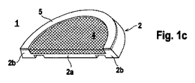
図1aから図1cは、本発明による固定部材1の第1の実施の形態を示している。固定部材1は、基体2を有している。基体2の前面は図1aに、かつ基体2の背面は図1bに示されている。図1cは、固定部材1の断面図を示している。基体2は、ガス非透過性かつ液体非透過性の中実の材料、特にアルミニウムのような金属製の材料から成っている。
1a to 1c show a first embodiment of a fixing
基体2は、円形ディスク形状を有している。本形態では、円形ディスク形状は完全に閉じられている。基体2の背面には、ピン、ねじ山および類似のアダプタ(図示せず)が設けられていてよく、これによって特定の対象物を固定部材1において支持し、かつ位置固定することができる。このように形成された固定部材1は、特に、浴室または衛生室における付属品の保持、または建物の内部または外部領域における対象物の位置固定のためにも使用され得る。たとえば、このような対象物には、植物を保持するための格子、カーテンレール、シャワー用異形材等がある。
The
基体2は、本形態では、円形ディスク状の基板2aを有している。この場合、基板2aの内面には、周方向に延びる環状の縁部セグメント2bが設けられている。縁部セグメント2bは、基板2aの内面を超えて突出している。基板2aの内面は、したがって縁部セグメント2bに対して凹まされている。
In the present embodiment, the
この凹所には親水性のインサート4が装入され、この凹所において位置固定されている。位置固定は、機械的な位置固定として、または接着材の形態で実現され得る。親水性のインサート4は、綿または繊維複合材料から成るプレート状の装入物の形態で形成されていてよい。択一的には、親水性のインサート4が、たとえばプラスチック、特殊鋼、または黄銅から成る焼結板から形成されていてよい。 A hydrophilic insert 4 is inserted into this recess, and the position is fixed in this recess. Positioning can be realized as mechanical positioning or in the form of an adhesive. The hydrophilic insert 4 may be formed in the form of a plate-shaped charge made of cotton or fiber composite material. Alternatively, the hydrophilic insert 4 may be formed from a sintered plate made of plastic, special steel or brass, for example.
親水性のインサート4はプレート状に形成されている。この場合、インサートの幾何学形状は基体2に適合されていて、親水性のインサート4は基体2aの内面の全面積にわたって延びていて、基体2の縁部セグメント2bに密に当て付けられている。択一的には親水性のインサート4は、基板2aの部分的な面積にわたって延びていてよい。
The hydrophilic insert 4 is formed in a plate shape. In this case, the geometry of the insert is adapted to the
親水性のインサート4の材料厚さは、このインサート4が縁部セグメント2bの上側の縁部に関して凹んで位置しているように選択される。
The material thickness of the hydrophilic insert 4 is selected such that the insert 4 is recessed relative to the upper edge of the
図1aおよび図1cから判るように、縁部セグメント2bの上縁部には位置固定リング5が被着されている。この位置固定リング5は、縁部セグメント2bの全周にわたって延びている。この位置固定リング5は、固定部材1が取り付けられるべき載着面(図示せず)に固定部材1を予備的に位置固定するために働く。有利には、位置固定リング5は、両面接着テープから成っている。
As can be seen from FIGS. 1a and 1c, a position fixing ring 5 is attached to the upper edge of the
固定部材1を持続的に載着面、たとえば建物の壁または天井に固定するためには、たとえば湿らせた布でこの親水性の素材を拭くことで、まず親水性のインサート4に配量されて適量の湿気が供給される。このように湿らされた親水性のインサート4には、好気性接着剤の層が塗布される。好気性接着剤は、シラン変性シリコーンポリマから成っている。次いで、固定部材1の基体2が載着面に設置され、これによって、所望の予備位置固定を得るために位置固定リング5と載着面との接触が生じる。したがって、好気性接着剤は、完全に閉じられた、載着面と基体2とにより形成された中空室内に配置されている。好気性接着剤のガス密かつ空気密な封入にもかかわらず、この接着剤は完全に硬化する。なぜならば、好気性接着剤には親水性のインサート4を介して硬化のために必要となる湿気が供給されるからである。親水性のインサート4への配量された湿気供給により、好気性接着剤は正確に、完全な硬化のために必要となる湿分量を得る。ガス密かつ液密な封入により、好気性接着剤は、周囲の影響、特に変動する空気湿度に対して保護されている。空気湿度は、好気性接着剤との接触時に、好気性のプラスチックに過剰にまたは過小に湿気を供給することにつながり、このことは好気性接着剤の不完全な硬化の結果となり得る。好気性接着剤の封入と、該好気性接着剤と湿らされた親水性のインサート4との接触とにより、好気性接着剤の完全な硬化が達成されるので、載着面における固定部材1の極めて良好かつ持続する保持が得られる。
In order to continuously fix the fixing
図2aから図2cは、図1aから図1cに示した実施の形態の変化形を示している。図2aから図2cによる実施の形態では、基板2aと、該基板2aに位置固定された親水性のインサート4とが孔6,7により貫通されている。それ以外の点では、図2aから図2cに示した実施の形態は、図1aから図1cに示した実施の形態に完全に一致している。
2a to 2c show variations of the embodiment shown in FIGS. 1a to 1c. In the embodiment according to FIGS. 2 a to 2 c, the
図2aから図2cに示した実施の形態では、まず親水性のインサート4が、調量されて適量に湿らされる。図1aから図1cに示した実施の形態とは異なり、この構成では、親水性のインサート4への好気性接着剤の塗布が行われる前に、固定部材1は位置固定リング5で載着面に予備的に位置固定され得る。この場合、載着面に予備的に位置固定された固定部材1において、1つまたは2つの孔を介して好気性接着剤が基体2と載着面との間の中空室内に導入される。このように導入された好気性接着剤は、載着面と親水性のインサート4との間で接着層を形成する。過剰な好気性接着剤は、孔7を介して流出する。孔6,7内に位置する好気性接着剤の残りは、この孔6,7を封鎖するので、好気性接着剤の層は、載着面と、親水性のインサートとの間で再び、図1aから図1cの実施の形態と同様に、ガス密かつ液密に封入されている。したがって、この場合も、好気性接着剤の接着層の管理された完全な硬化が載着面と親水性のインサート4との間で達成される。なぜならば、載着面と親水性のインサート4との間で、好気性接着剤は、適量の湿気を親水性のインサートから得るが、周辺雰囲気からは得ないからである。
In the embodiment shown in FIGS. 2a to 2c, the hydrophilic insert 4 is first weighed and moistened to an appropriate amount. Unlike the embodiment shown in FIGS. 1 a to 1 c, in this configuration, the fixing
孔6,7は、付加的な機能として、基体2内での親水性のインサート4の機械的な位置固定のために役立つ。この場合、特に孔6,7はリベット結合部の取付けのために使用され得る。
The
図3は、磁石保持部を有する固定部材1の実施の形態を示している。固定部材1は、本形態では、中空円柱状の基体2を有している。図3は、基体2の開いた上面から見た図を示している。基体2の内部には、磁石8が支持されている。磁石8は、基体2内に深く位置していて、この場合、この磁石には、基体2の開いた上面を介して自由にアクセス可能である。基体2の下面には、図1aから図1cの実施の形態による親水性のインサート4が位置している。好気性接着剤を親水性のインサート4に被着することにより、これにより形成された固定部材1が載着面に取り付けられ得る。
FIG. 3 shows an embodiment of the fixing
図4は、図3に示した固定部材1のための使用例を示している。固定部材1は、親水性のインサート4に被着された好気性接着剤を用いてたとえば自動車の壁エレメント9に固定されている。このゴミ容器10は、外壁にボールジョイントを有している。ボールジョイントの金属製のボール11は、固定部材1の開いた上面に押し込まれ、固定部材1内で磁力により磁石8に位置固定される。これによってゴミ容器は、固定部材1において揺動可能に支持されている。
FIG. 4 shows an example of use for the fixing
1 固定部材
2 基体
2a 基板
2b 縁部セグメント
4 親水性のインサート
5 位置固定リング
6 孔
7 孔
8 磁石
9 壁エレメント
10 ゴミ容器
11 ボール
DESCRIPTION OF
Claims (14)
前記基体(2)の、前記載着面に向けられた内面に、親水性のインサート(4)が被着されており、該親水性のインサート(4)には調量されて湿気が供給されていて、かつ該親水性のインサート(4)に好気性接着剤が被着可能であり、該好気性接着剤は、前記親水性のインサート(4)と共に、前記載着面と前記基体(2)とにより取り囲まれた中空室内にガス密かつ液密に封入されていることを特徴とする、ガス非透過性かつ液体非透過性の材料から成る基体(2)を備えた固定部材。 A fixing member having a base (2) made of a gas-impermeable and liquid-impermeable material, having means for containing an object and capable of being fixed to a mounting surface by an adhesive,
A hydrophilic insert (4) is applied to the inner surface of the base body (2) facing the wearing surface, and the hydrophilic insert (4) is metered and supplied with moisture. In addition, an aerobic adhesive can be applied to the hydrophilic insert (4), and the aerobic adhesive, together with the hydrophilic insert (4), includes the wearing surface and the substrate (2). A fixing member having a base (2) made of a gas-impermeable and liquid-impermeable material, which is sealed in a gas-tight and liquid-tight manner in a hollow chamber surrounded by
Applications Claiming Priority (3)
| Application Number | Priority Date | Filing Date | Title |
|---|---|---|---|
| DE102010056221A DE102010056221A1 (en) | 2010-12-24 | 2010-12-24 | fasteners |
| DE102010056221.1 | 2010-12-24 | ||
| PCT/EP2011/071826 WO2012084476A1 (en) | 2010-12-24 | 2011-12-06 | Fastener |
Publications (2)
| Publication Number | Publication Date |
|---|---|
| JP2014503772A JP2014503772A (en) | 2014-02-13 |
| JP5939261B2 true JP5939261B2 (en) | 2016-06-22 |
Family
ID=45093766
Family Applications (1)
| Application Number | Title | Priority Date | Filing Date |
|---|---|---|---|
| JP2013545160A Expired - Fee Related JP5939261B2 (en) | 2010-12-24 | 2011-12-06 | Fixed member |
Country Status (10)
| Country | Link |
|---|---|
| US (1) | US9441659B2 (en) |
| EP (1) | EP2655899B1 (en) |
| JP (1) | JP5939261B2 (en) |
| CN (1) | CN103270322B (en) |
| AU (1) | AU2011347906A1 (en) |
| BR (1) | BR112013015729A2 (en) |
| DE (1) | DE102010056221A1 (en) |
| ES (1) | ES2636674T3 (en) |
| RU (1) | RU2556516C2 (en) |
| WO (1) | WO2012084476A1 (en) |
Cited By (1)
| Publication number | Priority date | Publication date | Assignee | Title |
|---|---|---|---|---|
| US10890202B2 (en) | 2016-08-23 | 2021-01-12 | Tesa Se | Fastening element with a non-permeable adhesive ring |
Families Citing this family (40)
| Publication number | Priority date | Publication date | Assignee | Title |
|---|---|---|---|---|
| DE202013004203U1 (en) * | 2012-12-07 | 2013-05-21 | Ortwein Gmbh | shower system |
| DE202012105010U1 (en) | 2012-12-21 | 2014-03-24 | Ortwein Gmbh | Clamp pipe clip fastener for gluing |
| DE202012105009U1 (en) * | 2012-12-21 | 2014-03-24 | Ortwein Gmbh | Universal system kit for fixtures |
| DE202012105008U1 (en) | 2012-12-21 | 2014-03-24 | Ortwein Gmbh | Easy-to-install connection systems for sanitary products |
| DE202013102982U1 (en) | 2013-04-09 | 2014-07-14 | Glabete Gmbh | Magnetic system kit and equipment series |
| DE102013208619A1 (en) * | 2013-05-10 | 2014-11-13 | Conex Ipr Ltd. | Holding device |
| US10925417B2 (en) | 2014-01-22 | 2021-02-23 | Ccl Label, Inc. | Secure hold hook |
| DE202014101631U1 (en) | 2014-04-07 | 2014-04-14 | Ortwein Gmbh | Adhesive for fixing two objects |
| KR101832753B1 (en) * | 2015-05-08 | 2018-02-27 | (주)바텍이우홀딩스 | Apparatus for scanning for both model and oral cavity |
| DE102015114905A1 (en) * | 2015-09-06 | 2017-03-09 | Nie Wieder Bohren Ag | Fastener for stationary attachment of objects to a mounting pad |
| USD802404S1 (en) * | 2016-03-10 | 2017-11-14 | Sariana, LLC | Magnet clip mount |
| USD852150S1 (en) | 2016-03-10 | 2019-06-25 | Sariana, LLC | Magnet mount |
| EP3225856B1 (en) | 2016-03-30 | 2018-11-28 | Aufrecht GmbH | Mounter |
| DE102016010725A1 (en) * | 2016-09-05 | 2018-03-08 | Tesa Nie Wieder Bohren Gmbh | Sandwich adapter for attaching an object to an area in an environment |
| USD855054S1 (en) | 2016-11-25 | 2019-07-30 | Sariana, LLC | Multiport USB hub |
| USD830366S1 (en) | 2016-11-25 | 2018-10-09 | Sariana, LLC | Multiport USB hub for computer |
| EP3892870B1 (en) * | 2017-05-19 | 2023-01-11 | Dieter Ronnenberg | Mounting system |
| USD862385S1 (en) | 2017-11-20 | 2019-10-08 | Sariana, LLC | Multi-port adapter |
| USD856278S1 (en) | 2017-11-20 | 2019-08-13 | Sariana, LLC | Multi-port adapter |
| USD868784S1 (en) | 2018-05-23 | 2019-12-03 | Sariana, LLC | Media card reader for electronics devices |
| USD919627S1 (en) | 2018-07-25 | 2021-05-18 | Sariana, LLC | Electronic hub with opening data port |
| USD895551S1 (en) | 2018-10-29 | 2020-09-08 | Sariana, LLC | Two in one connector |
| USD879102S1 (en) | 2018-10-29 | 2020-03-24 | Sariana, LLC | Hub for smart phone |
| USD894191S1 (en) | 2018-11-13 | 2020-08-25 | Sariana, LLC | Hub with stand for mini computer |
| USD895625S1 (en) | 2019-04-17 | 2020-09-08 | Sariana, LLC | Adapter for a computer |
| USD906959S1 (en) | 2019-07-03 | 2021-01-05 | Sariana, LLC | Charging adapter |
| USD909386S1 (en) | 2019-07-09 | 2021-02-02 | Sariana, LLC | Adapter for a computer |
| USD971831S1 (en) | 2019-07-11 | 2022-12-06 | Sariana Llc | Wireless charger |
| USD957326S1 (en) | 2019-07-11 | 2022-07-12 | Sariana, LLC | Wireless charger |
| USD957325S1 (en) | 2019-07-11 | 2022-07-12 | Sariana, LLC | Wireless charger |
| USD911346S1 (en) | 2019-07-29 | 2021-02-23 | Sariana, LLC | Multiport connecting hub for a computer |
| USD911946S1 (en) | 2019-07-30 | 2021-03-02 | Sariana, LLC | Wireless charger |
| USD911955S1 (en) | 2019-08-29 | 2021-03-02 | Sariana, LLC | Charger for electronic devices |
| USD936572S1 (en) | 2019-11-18 | 2021-11-23 | Sariana, LLC | Charger for electronic devices |
| USD924132S1 (en) | 2019-12-11 | 2021-07-06 | Sariana, LLC | Wireless charger and power bank |
| USD936574S1 (en) | 2020-01-08 | 2021-11-23 | Sariana, LLC | Charger for electronic devices |
| USD936573S1 (en) | 2020-01-08 | 2021-11-23 | Sariana, LLC | Charger for electronic devices |
| USD958737S1 (en) | 2020-07-22 | 2022-07-26 | Sariana, LLC | Wireless charger |
| CN112727922B (en) * | 2020-12-24 | 2022-11-08 | 北华航天工业学院 | Magnetic-liquid double-suspension bearing coating treatment method for reducing friction loss and improving static pressure bearing performance |
| USD1006769S1 (en) * | 2022-08-24 | 2023-12-05 | Xuefeng Jiang | Magnet |
Family Cites Families (21)
| Publication number | Priority date | Publication date | Assignee | Title |
|---|---|---|---|---|
| US3239178A (en) * | 1964-07-14 | 1966-03-08 | Joseph B Pompa | Magnetic and adhesive mounting support |
| JPS5730076U (en) * | 1980-07-30 | 1982-02-17 | ||
| SU1588932A1 (en) * | 1988-06-13 | 1990-08-30 | Институт Проблем Механики Ан Ссср | Gripping device |
| US5065489A (en) * | 1988-07-28 | 1991-11-19 | Eastman Kodak Company | Apparatus for aligning and mounting machine components |
| AU3071892A (en) * | 1991-11-12 | 1993-06-15 | Selfix, Inc. | Molded plastic load-bearing support device |
| AU7926594A (en) * | 1993-10-01 | 1995-05-01 | Selfix, Inc. | Encapsulated adhesive system for a load-bearing support device |
| DE4416884A1 (en) * | 1994-05-13 | 1995-11-23 | Daimler Benz Aerospace Ag | Solar generator panel mechanical attachment appts. |
| US5593120A (en) * | 1994-11-21 | 1997-01-14 | Minnesota Mining And Manufacturing Company | Quick-mounting fastening assembly |
| FR2768471B1 (en) * | 1997-09-12 | 1999-11-19 | M Et G S | DEVICE FOR FIXING AN OBJECT ONTO A SURFACE, PARTICULARLY ON A WALL OR FLOOR, USING A PUTTY ADHESIVE |
| JPH11182529A (en) * | 1997-12-16 | 1999-07-06 | Maguna:Kk | Ball joint |
| AU2001267377A1 (en) * | 2000-04-25 | 2001-11-07 | Ernst Georg Ortwein | Method and mounting system for fixing a fastening element on a wall |
| DE10152052A1 (en) * | 2001-10-25 | 2003-05-08 | Ernst-Georg Ortwein | Mounting system for attaching fasteners to a wall |
| JP4342187B2 (en) * | 2003-01-22 | 2009-10-14 | 協立エアテック株式会社 | Hanging equipment |
| JP2005146126A (en) * | 2003-11-17 | 2005-06-09 | Hori Glass Kk | Method for bonding with moisture-curing type adhesive |
| NL1027196C2 (en) * | 2004-10-07 | 2006-04-10 | Anton Rudolf Enserink | Device is for fixture on base by means of two or more component-adhesive and comprises one or more breakably sealed and movably arranged parts each filled with one of the adhesive components |
| JP2006130168A (en) * | 2004-11-09 | 2006-05-25 | Tomizo Takizawa | Locking implement |
| CN102076742B (en) | 2008-06-27 | 2013-12-25 | 格拉贝特股份公司 | Fastening composition and process for fixing article to substrate |
| DE102008037095B3 (en) * | 2008-08-08 | 2010-04-29 | Nie Wieder Bohren Ag | Fastening element for fixed attachment of objects to a wall and method for curing a bonding and connecting means, by means of which the fastening element is fixed to the wall |
| DE102008058389A1 (en) * | 2008-11-21 | 2010-05-27 | Sfs Intec Holding Ag | Fastener point, useful for a fastening surface of a component part e.g. a glass plate, comprises a contact element with a contact site and a connection element, where the contact point is formed by an adhesive placed on fixing surface |
| DE202009003176U1 (en) * | 2009-03-10 | 2010-07-22 | Glabete Ag | fastener |
| US8545647B2 (en) * | 2009-11-19 | 2013-10-01 | Pilkington Group Limited | Item of hardware and method of making and bonding same |
-
2010
- 2010-12-24 DE DE102010056221A patent/DE102010056221A1/en not_active Withdrawn
-
2011
- 2011-12-06 BR BR112013015729A patent/BR112013015729A2/en not_active IP Right Cessation
- 2011-12-06 AU AU2011347906A patent/AU2011347906A1/en not_active Abandoned
- 2011-12-06 WO PCT/EP2011/071826 patent/WO2012084476A1/en active Application Filing
- 2011-12-06 US US13/997,467 patent/US9441659B2/en active Active
- 2011-12-06 JP JP2013545160A patent/JP5939261B2/en not_active Expired - Fee Related
- 2011-12-06 ES ES11790983.8T patent/ES2636674T3/en active Active
- 2011-12-06 CN CN201180062364.7A patent/CN103270322B/en not_active Expired - Fee Related
- 2011-12-06 EP EP11790983.8A patent/EP2655899B1/en active Active
- 2011-12-06 RU RU2013131905/12A patent/RU2556516C2/en not_active IP Right Cessation
Cited By (1)
| Publication number | Priority date | Publication date | Assignee | Title |
|---|---|---|---|---|
| US10890202B2 (en) | 2016-08-23 | 2021-01-12 | Tesa Se | Fastening element with a non-permeable adhesive ring |
Also Published As
| Publication number | Publication date |
|---|---|
| JP2014503772A (en) | 2014-02-13 |
| US9441659B2 (en) | 2016-09-13 |
| US20130272775A1 (en) | 2013-10-17 |
| ES2636674T3 (en) | 2017-10-06 |
| EP2655899A1 (en) | 2013-10-30 |
| RU2013131905A (en) | 2015-01-27 |
| AU2011347906A1 (en) | 2013-07-18 |
| DE102010056221A1 (en) | 2012-06-28 |
| CN103270322B (en) | 2015-05-13 |
| CN103270322A (en) | 2013-08-28 |
| WO2012084476A1 (en) | 2012-06-28 |
| RU2556516C2 (en) | 2015-07-10 |
| EP2655899B1 (en) | 2017-03-15 |
| BR112013015729A2 (en) | 2018-05-15 |
Similar Documents
| Publication | Publication Date | Title |
|---|---|---|
| JP5939261B2 (en) | Fixed member | |
| JP4856359B2 (en) | Assembly device for attaching a mounting member to a surface | |
| RU2482150C2 (en) | Adhesive composition and method of attaching article to substrate | |
| US10077792B2 (en) | Device and method for forming an adhesive connection between an article and a support | |
| DK2154384T3 (en) | Fastener for stationary application of articles to a wall and method of curing an adhesive and bonding means by means of which the fastener is affixed to the wall | |
| CN109863316B (en) | Method of attaching a base of a fastening element to a surface and fastening element for attaching an object to a surface | |
| JP5780972B2 (en) | Coupling means | |
| JP2012519763A5 (en) | ||
| US20130056598A1 (en) | Mounting system | |
| US10690163B2 (en) | Fastener | |
| US20120205027A1 (en) | Assembly kit for supplying a fixing agent and method for fixing an object on a base | |
| CA2508371A1 (en) | Device and method for fastening facade plates | |
| JP3109156U (en) | Interior material |
Legal Events
| Date | Code | Title | Description |
|---|---|---|---|
| A621 | Written request for application examination |
Free format text: JAPANESE INTERMEDIATE CODE: A621 Effective date: 20141105 |
|
| A977 | Report on retrieval |
Free format text: JAPANESE INTERMEDIATE CODE: A971007 Effective date: 20151130 |
|
| A131 | Notification of reasons for refusal |
Free format text: JAPANESE INTERMEDIATE CODE: A131 Effective date: 20151207 |
|
| A521 | Request for written amendment filed |
Free format text: JAPANESE INTERMEDIATE CODE: A523 Effective date: 20160204 |
|
| TRDD | Decision of grant or rejection written | ||
| A01 | Written decision to grant a patent or to grant a registration (utility model) |
Free format text: JAPANESE INTERMEDIATE CODE: A01 Effective date: 20160404 |
|
| A711 | Notification of change in applicant |
Free format text: JAPANESE INTERMEDIATE CODE: A711 Effective date: 20160425 |
|
| A61 | First payment of annual fees (during grant procedure) |
Free format text: JAPANESE INTERMEDIATE CODE: A61 Effective date: 20160502 |
|
| A521 | Request for written amendment filed |
Free format text: JAPANESE INTERMEDIATE CODE: A821 Effective date: 20160425 |
|
| R150 | Certificate of patent or registration of utility model |
Ref document number: 5939261 Country of ref document: JP Free format text: JAPANESE INTERMEDIATE CODE: R150 |
|
| R250 | Receipt of annual fees |
Free format text: JAPANESE INTERMEDIATE CODE: R250 |
|
| R250 | Receipt of annual fees |
Free format text: JAPANESE INTERMEDIATE CODE: R250 |
|
| R250 | Receipt of annual fees |
Free format text: JAPANESE INTERMEDIATE CODE: R250 |
|
| R250 | Receipt of annual fees |
Free format text: JAPANESE INTERMEDIATE CODE: R250 |
|
| LAPS | Cancellation because of no payment of annual fees |