JP5937546B2 - Filament winding equipment - Google Patents
Filament winding equipment Download PDFInfo
- Publication number
- JP5937546B2 JP5937546B2 JP2013127180A JP2013127180A JP5937546B2 JP 5937546 B2 JP5937546 B2 JP 5937546B2 JP 2013127180 A JP2013127180 A JP 2013127180A JP 2013127180 A JP2013127180 A JP 2013127180A JP 5937546 B2 JP5937546 B2 JP 5937546B2
- Authority
- JP
- Japan
- Prior art keywords
- winding
- fiber bundle
- resin
- helical
- fiber
- Prior art date
- Legal status (The legal status is an assumption and is not a legal conclusion. Google has not performed a legal analysis and makes no representation as to the accuracy of the status listed.)
- Active
Links
- 238000009730 filament winding Methods 0.000 title claims description 18
- 239000000835 fiber Substances 0.000 claims description 220
- 238000004804 winding Methods 0.000 claims description 215
- 229920005989 resin Polymers 0.000 claims description 154
- 239000011347 resin Substances 0.000 claims description 154
- 238000005470 impregnation Methods 0.000 claims description 92
- 229920001187 thermosetting polymer Polymers 0.000 claims description 49
- 238000000034 method Methods 0.000 claims description 8
- 230000008569 process Effects 0.000 claims description 4
- 229920000049 Carbon (fiber) Polymers 0.000 description 102
- 239000004917 carbon fiber Substances 0.000 description 102
- VNWKTOKETHGBQD-UHFFFAOYSA-N methane Chemical compound C VNWKTOKETHGBQD-UHFFFAOYSA-N 0.000 description 102
- 239000010410 layer Substances 0.000 description 99
- 238000009826 distribution Methods 0.000 description 20
- 239000007789 gas Substances 0.000 description 18
- 230000007246 mechanism Effects 0.000 description 12
- 238000003825 pressing Methods 0.000 description 11
- 238000005192 partition Methods 0.000 description 8
- 238000011144 upstream manufacturing Methods 0.000 description 8
- 238000004519 manufacturing process Methods 0.000 description 7
- 238000010586 diagram Methods 0.000 description 5
- 239000012467 final product Substances 0.000 description 5
- UFHFLCQGNIYNRP-UHFFFAOYSA-N Hydrogen Chemical compound [H][H] UFHFLCQGNIYNRP-UHFFFAOYSA-N 0.000 description 4
- OKTJSMMVPCPJKN-UHFFFAOYSA-N Carbon Chemical compound [C] OKTJSMMVPCPJKN-UHFFFAOYSA-N 0.000 description 3
- 241000239366 Euphausiacea Species 0.000 description 3
- 229910052799 carbon Inorganic materials 0.000 description 3
- 238000001723 curing Methods 0.000 description 3
- 239000003822 epoxy resin Substances 0.000 description 3
- 238000010438 heat treatment Methods 0.000 description 3
- 229920000647 polyepoxide Polymers 0.000 description 3
- 230000004888 barrier function Effects 0.000 description 2
- 230000015572 biosynthetic process Effects 0.000 description 2
- 239000011162 core material Substances 0.000 description 2
- 238000006073 displacement reaction Methods 0.000 description 2
- 229910052739 hydrogen Inorganic materials 0.000 description 2
- 239000001257 hydrogen Substances 0.000 description 2
- 238000007654 immersion Methods 0.000 description 2
- 239000013067 intermediate product Substances 0.000 description 2
- 239000002356 single layer Substances 0.000 description 2
- 238000003860 storage Methods 0.000 description 2
- 239000004677 Nylon Substances 0.000 description 1
- -1 as described above Substances 0.000 description 1
- 238000001816 cooling Methods 0.000 description 1
- 238000005520 cutting process Methods 0.000 description 1
- 230000000694 effects Effects 0.000 description 1
- 238000013007 heat curing Methods 0.000 description 1
- 230000006872 improvement Effects 0.000 description 1
- 230000006698 induction Effects 0.000 description 1
- 238000012423 maintenance Methods 0.000 description 1
- 238000002844 melting Methods 0.000 description 1
- 230000008018 melting Effects 0.000 description 1
- 229920001778 nylon Polymers 0.000 description 1
- 230000002093 peripheral effect Effects 0.000 description 1
- 239000012466 permeate Substances 0.000 description 1
- 239000000047 product Substances 0.000 description 1
- 230000009467 reduction Effects 0.000 description 1
Images


Landscapes
- Moulding By Coating Moulds (AREA)
Description
本発明は、フィラメントワインディング装置に関する。 The present invention relates to a filament winding apparatus.
フィラメントワインディング装置(以下、適宜、FW装置と略称する)は、高圧ガスタンクのコアである樹脂製のライナー等の繊維巻回対象物に多数本の繊維を繊維束の形態で巻回するものとして、広く普及している。FW装置では、繊維束の巻回終了タイミングで、繊維束末端を既に巻回済みの繊維束に固定する必要があり、種々の固定手法が提案されている(例えば、特許文献1)。 A filament winding device (hereinafter, abbreviated as FW device as appropriate) is a device that winds a large number of fibers in the form of a fiber bundle around a fiber winding object such as a resin liner that is the core of a high-pressure gas tank. Widely used. In the FW device, it is necessary to fix the end of the fiber bundle to the already wound fiber bundle at the end of winding of the fiber bundle, and various fixing methods have been proposed (for example, Patent Document 1).
上記の繊維束末端の固定手法では、繊維束に含まれる繊維に含浸した熱硬化性樹脂より高融点の留め部材を用いる都合上、この留め部材の繊維束への装着、並びに、高低2段階の加熱処理が必要となる。このため、繊維束末端の固定の簡便化や簡略化が要請されるに到った。その他、FW装置による繊維束の巻回を経て得られる最終製品の品質向上などを図ることも要請されている。 In the above-described fixing method of the fiber bundle, for the convenience of using a fixing member having a melting point higher than that of the thermosetting resin impregnated in the fiber included in the fiber bundle, the fixing member is attached to the fiber bundle, and the two steps of high and low are used. Heat treatment is required. For this reason, it came to be requested to simplify and simplify the fixing of the fiber bundle end. In addition, it is also required to improve the quality of the final product obtained by winding the fiber bundle with the FW device.
上記した課題の少なくとも一部を達成するために、本発明は、以下の形態として実施することができる。 In order to achieve at least a part of the problems described above, the present invention can be implemented as the following forms.
(1)本発明の一形態によれば、フィラメントワインディング装置が提供される。このフィラメントワインディング装置は、繊維巻回対象物に多数本の繊維を繊維束の形態で巻回するフィラメントワインディング装置であって、前記繊維束を巻き取り済みの繊維ボビンを、前記繊維束を送り出し可能に保持するボビンユニットと、前記繊維巻回対象物の軸芯に沿って相対的に往復動し、供給を受けた前記繊維束を前記往復動の過程で前記繊維巻回対象物の外表面に巻回する繊維巻回部と、該繊維巻回部により前記繊維巻回対象物に巻回される前記繊維束を熱硬化性樹脂溶液に接触させ、該熱硬化性樹脂溶液との接触状態を制御して前記繊維束への前記熱硬化性樹脂溶液の含浸量を調整する含浸調整部とを備える。該含浸調整部は、前記繊維巻回部による前記繊維束の巻回終了タイミングで前記繊維巻回対象物に巻回される繊維束末端領域において、前記含浸量を増大調整する。 (1) According to one aspect of the present invention, a filament winding apparatus is provided. This filament winding apparatus is a filament winding apparatus for winding a large number of fibers around a fiber winding object in the form of a fiber bundle, and the fiber bobbin on which the fiber bundle has been wound can be sent out. The bobbin unit held on the fiber winding object and the fiber winding object are relatively reciprocated along the axis of the fiber winding object, and the supplied fiber bundle is moved to the outer surface of the fiber winding object in the reciprocation process. and the fiber winding portion for winding, the fiber bundle wound around the fiber 維巻times object by the fiber winding portion is brought into contact with the thermosetting resin solution, the state of contact between the thermosetting resin solution And an impregnation adjusting unit for adjusting the amount of impregnation of the thermosetting resin solution into the fiber bundle. Impregnation adjusting section in the fiber bundle end region in the winding end timing of the fiber bundle by fiber winding portion wound around the fiber 維巻times the object increases adjusting the amount of impregnation.
上記形態のフィラメントワインディング装置は、繊維束の巻回終了タイミングで繊維巻回対象物に巻回される繊維束末端領域を、熱硬化性樹脂の含浸量が増大調整された状態とするので、この増大含浸した熱硬化性樹脂にて、繊維束末端領域を巻回済みの繊維束に容易に仮止めできる。その上で、増大含浸させた熱硬化性樹脂の熱硬化により、巻回済みの繊維束に固定できる。よって、上記形態のフィラメントワインディング装置によれば、繊維束末端領域の固定のための他の部材が不要となると共に、繊維束を硬化・固定するための熱硬化性樹脂の熱硬化処理についても一度で済むので、簡便である。 The form of filament winding apparatus, the fiber bundle end region wound around the fiber 維巻times the object at the winding end timing of the fiber bundle, since the state of impregnation of the thermosetting resin is increased adjusted, With this increased and impregnated thermosetting resin, the fiber bundle end region can be easily temporarily attached to the wound fiber bundle. On that basis, it can be fixed to the wound fiber bundle by thermosetting the thermosetting resin impregnated with increasing amount. Therefore, according to the filament winding apparatus of the above embodiment, other members for fixing the fiber bundle end region are not necessary, and the thermosetting treatment of the thermosetting resin for curing and fixing the fiber bundle is also performed once. It is easy because
(2)上記した形態のフィラメントワインディング装置において、前記繊維巻回部として、前記繊維巻回対象物に繊維束をフープ巻きするフープ巻部と、前記繊維巻回対象物に繊維束をヘリカル巻きするヘリカル巻部とを備え、前記含浸調整部は、前記ヘリカル巻部での前記繊維束末端領域における前記含浸量を、前記フープ巻部での前記繊維束末端領域における前記含浸量より多く調整するようにできる。ヘリカル巻きでは、繊維束の巻回軌跡が繊維巻回対象物の中心軸に対して低角度の繊維角(例えば、約11〜25°)で交差し、フープ巻きでは中心軸に対してほぼ垂直に近い繊維角(例えば約89°)で交差する。よって、ヘリカル巻き繊維束は、フープ巻き繊維束より、一般に滑りやすくなる。この形態のフィラメントワインディング装置では、上記のように滑りやすいヘリカル巻きの繊維束末端領域を、フープ巻き繊維束より熱硬化性樹脂の含浸量が増大調整された状態とするので、滑りやすいヘリカル巻きの繊維束末端領域を、巻回済みのヘリカル巻回の繊維束に、増大含浸させた熱硬化性樹脂により容易、且つ確実に仮止めできる。その上で、増大含浸させた熱硬化性樹脂の熱硬化により、巻回済みの繊維束により確実に固定できる。このため、この形態のフィラメントワインディング装置によれば、繊維束のヘリカル巻きおよびフープ巻きを経て得られる最終製品において、ヘリカル巻き繊維束のズレが抑制されることから、製品品質の向上に寄与できる。 (2) In the filament winding apparatus of the above-described form, as the fiber winding unit, a hoop winding unit that hoops a fiber bundle around the fiber winding object, and a fiber bundle is helically wound around the fiber winding object. A helical winding portion, and the impregnation adjusting portion adjusts the impregnation amount in the fiber bundle end region in the helical winding portion to be larger than the impregnation amount in the fiber bundle end region in the hoop winding portion. Can be. In helical winding, the winding trajectory of the fiber bundle intersects the central axis of the fiber winding object at a low angle fiber angle (for example, about 11 to 25 °), and in hoop winding, it is almost perpendicular to the central axis. Intersect at a fiber angle close to (for example, about 89 °). Therefore, the helically wound fiber bundle is generally easier to slip than the hoop wound fiber bundle. In the filament winding apparatus of this embodiment, the slippery helically wound fiber bundle end region is in a state in which the amount of impregnation of the thermosetting resin is increased and adjusted as compared with the hoop wound fiber bundle. The fiber bundle end region can be easily and reliably temporarily fixed by the thermosetting resin impregnated in the helically wound fiber bundle. In addition, it can be reliably fixed by the wound fiber bundle by the thermosetting of the thermosetting resin impregnated and increased. For this reason, according to the filament winding apparatus of this embodiment, in the final product obtained through the helical winding and hoop winding of the fiber bundle, the displacement of the helically wound fiber bundle is suppressed, which can contribute to the improvement of product quality.
(3)上記した形態のフィラメントワインディング装置において、前記ヘリカル巻部によるヘリカル巻きと前記フープ巻部によるフープ巻きとを繰り返し、ヘリカル層とフープ層とを交互に前記繊維巻回対象物に積層形成し、前記含浸調整部は、前記繊維束末端領域における前記含浸量の調整に加え、内層側のヘリカル層の形成のための前記ヘリカル巻部によるヘリカル巻きの際には、外層側のヘリカル層の形成のための前記ヘリカル巻部によるヘリカル巻きの場合より前記含浸量を多く調整するようにできる。こうすれば、内層側に形成されたヘリカル層に多く含浸されていた熱硬化性樹脂を、外層側に形成されるヘリカル層に染み渡るようにできるので、内層側のヘリカル層に含浸した熱硬化性樹脂を有効利用できる。 (3) In the filament winding apparatus of the above-described form, the helical winding by the helical winding part and the hoop winding by the hoop winding part are repeated, and the helical layer and the hoop layer are alternately laminated on the fiber winding object. In addition to the adjustment of the amount of impregnation in the fiber bundle end region, the impregnation adjusting unit forms an outer layer-side helical layer during helical winding by the helical winding unit for forming an inner layer-side helical layer. The amount of impregnation can be adjusted more than in the case of helical winding by the helical winding portion. In this way, the thermosetting resin that is heavily impregnated in the helical layer formed on the inner layer side can permeate the helical layer formed on the outer layer side, so the thermosetting resin impregnated in the helical layer on the inner layer side. Resin can be used effectively.
なお、本発明は、種々の形態で実現することが可能であり、例えば、ライナーに多数本の繊維を繊維束の形態で巻回した高圧ガスタンクの他、高圧ガスタンクの製造装置或いは製造方法として構成することもできる。 The present invention can be realized in various forms. For example, the present invention is configured as a manufacturing apparatus or a manufacturing method for a high-pressure gas tank in addition to a high-pressure gas tank in which a large number of fibers are wound around a liner in the form of a fiber bundle. You can also
以下、本発明の実施の形態について、図面に基づき説明する。本実施形態のフィラメントワインディング装置(FW装置)は、最終製品としての高圧ガスタンクを製造する際に使用され、ライナー10に樹脂含浸カーボン繊維束Wを巻回する。図1は本発明の実施形態としてのFW装置100の概略構成を模式的に示す説明図、図2はFW装置100の要部であるヘリカル巻きユニット100Hと樹脂含浸カーボン繊維束Wの送り出しを図るボビンユニット120との概略的な位置関係を示す説明図、図3は繊維強化樹脂層の形成の様子を模式的に示す説明図である。本実施形態では、高圧ガスタンクを、高圧水素を貯蔵する高圧水素タンクとした。
Hereinafter, embodiments of the present invention will be described with reference to the drawings. The filament winding apparatus (FW apparatus) of this embodiment is used when a high-pressure gas tank as a final product is manufactured, and a resin-impregnated carbon fiber bundle W is wound around a
FW装置100は、水素ガスに対するガスバリア性を有する樹脂製容器のライナー10を繊維巻回対象物とする。ライナー10は、半径が均一である略円筒形状のシリンダー部10aと、シリンダー部両端に設けられた凸曲面形状のドーム部10bを有する。ドーム部10bは、等張力曲面によって構成されており、その頂点に、外部配管等と接続するための口金14を有する。本実施形態では、樹脂容器として、ナイロン系樹脂からなる樹脂製容器を用いるものとした。樹脂容器として、水素ガスに対するガスバリア性を有すれば、他の樹脂からなる樹脂容器を用いるものとしてもよい。
The
FW装置100は、ライナー軸支シャフト102と、ヘリカル巻きユニット100Hと、フープ巻きユニット100Fと、クリルスタンド110と、繊維束樹脂含浸分配ユニット150と、制御装置160とを有する。ライナー軸支シャフト102は、ライナー両端の口金14に挿入され、ライナー両端からシャフトを出した状態で後述する支持台310にて保持され、ライナー10を水平に軸支する。こうしてライナー10を軸支した後、FW装置100は、ヘリカル巻きユニット100Hとフープ巻きユニット100Fとにより、ライナー10の外周に樹脂含浸カーボン繊維束Wを巻回して、繊維強化樹脂層を形成する(繊維強化樹脂層形成工程)。この繊維強化樹脂層形成工程により、ライナー10の外周に樹脂硬化前の繊維強化樹脂層を有する中間生成品タンクが得られ、この中間生成品タンクを、図示しない誘導加熱装置等を用いて熱処理することで、最終製品としての高圧ガスタンクが得られる。
The
ヘリカル巻きユニット100Hは、図2に斜視にて示すように、ライナー10を取り囲む環状体の繊維束案内フレーム202を、基台300に固定フレーム204にて固定して備える。このヘリカル巻きユニット100Hは、ライナー両端のドーム部10bの湾曲外表面領域に樹脂含浸カーボン繊維束Wを掛け渡してヘリカル巻きを図るべく、ライナー10におけるタンク中心軸AXに沿って、繊維束案内フレーム202とライナー10とを、ドーム部10bの外側を含む所定範囲に亘って相対的に往復駆動させる。つまり、ライナー10に対して繊維束案内フレーム202を往復動させるようにできるほか、繊維束案内フレーム202に対して、ライナー10を水平に軸支したまま往復動させてもよい。本実施形態では、繊維束案内フレーム202を含むヘリカル巻きユニット100Hを基台300に固定してライナー10を往復動する構成としたが、図1では、図示の都合から、ヘリカル巻きユニット100Hを相対的にライナー10に対して往復動するよう示した。
As shown in a perspective view in FIG. 2, the
基台300は、第1レール302と、第2レール304と、支持台310とを備えている。第1レール302は、基台300の長手方向に延伸する一対の溝であり、基台300の上方向(Y方向)の面に形成されている。第2レール304は、基台300の長手方向に延伸する一対の溝であり、基台300の上面であって、第1レール302に対して基台300の短手方向(Z方向)の外側に形成されている。
The
支持台310は、基台300の上面に配置され、既述したライナー軸支シャフト102と共にライナー10を回転自在に支持する。支持台310は、ヘリカル巻きユニット100Hおよびフープ巻きユニット100Fを挟んで一対用意され、タンク中心軸AXを中心にライナー10を回転する。一対の支持台310は、図示しない駆動機構によって、基台300の長手方向に沿って第1レール302上を往復動自在に駆動し、ライナー10を繊維束案内フレーム202に対して往復動させる。支持台310は、ベース312と、支持腕314と、チャック316とを備えている。ベース312は、板状を有し、第1レール302に嵌合することで第1レール302上を移動可能に構成されている。支持腕314は、四角柱状を有し、基台300の上方向に向かって延伸するように設けられている。チャック316は、支持腕314の上端部、換言すれば、支持腕314がベース312に固定されている側とは反対側の端部に設けられており、ライナー軸支シャフト102を固定する。
The support base 310 is disposed on the upper surface of the
基台300に固定された繊維束案内フレーム202は、支持台310にて軸支されたライナー10が入り込む貫通孔の周囲に、複数個の繊維束案内体210を当ピッチに放射状に備える。それぞれの繊維束案内体210は、後述の繊維束樹脂含浸分配ユニット150から樹脂含浸カーボン繊維束Wの供給を受け、その供給を受けた樹脂含浸カーボン繊維束Wを、既述した繊維束案内フレーム202の相対的な往復動の過程でライナー10の外表面に案内して巻回する。
The fiber
クリルスタンド110は、図1に示すように、ヘリカル巻きユニット100Hの左右(図における上下)に配設され、繊維束案内フレーム202に設けられた繊維束案内体210の個数に相当する数のボビンユニット120を有する。それぞれのボビンユニット120は、樹脂含浸カーボン繊維束Wを巻き取り済みの繊維ボビンBを回転可能に保持し、これらボビンから、繊維束樹脂含浸分配ユニット150を経てヘリカル巻きユニット100Hの繊維束案内体210に樹脂含浸カーボン繊維束Wを送り出す。この場合、ボビンユニット120は、制御装置160の制御を受けて繊維ボビンBを回転させて樹脂含浸カーボン繊維束Wを送り出すようにできるほか、ライナー10への樹脂含浸カーボン繊維束Wの巻回に伴う引っ張り力により、繊維ボビンBから樹脂含浸カーボン繊維束Wを送り出すようにしてもよい。
As shown in FIG. 1, the crill stand 110 is disposed on the left and right sides (upper and lower sides in the drawing) of the helical winding
繊維束樹脂含浸分配ユニット150は、それぞれのボビンユニット120が送り出した樹脂含浸カーボン繊維束Wを熱硬化性樹脂に改めて含浸させた上で、その樹脂含浸カーボン繊維束Wを繊維束案内フレーム202に組み込まれた個々の繊維束案内体210に、供給する。この繊維束樹脂含浸分配ユニット150の構成については後述する。なお、ヘリカル巻きユニット100Hがライナー10に対して往復動する構成であれば、この繊維束樹脂含浸分配ユニット150は、ヘリカル巻きユニット100Hの往復動に合わせて移動し、クリルスタンド110の個々のボビンユニット120からの樹脂含浸カーボン繊維束Wをヘリカル巻きユニット100Hに案内しつつ送り出す。
The fiber bundle resin impregnation /
こうして樹脂含浸カーボン繊維束Wの供給を受けるヘリカル巻きユニット100Hは、図3(A)に示すように、樹脂含浸カーボン繊維束Wの巻回軌跡がタンク中心軸AXに対して低角度の繊維角αLH(例えば、約11〜25°)で交差する低角度のヘリカル巻きにて、樹脂含浸カーボン繊維束Wを巻回する。この樹脂含浸カーボン繊維束Wは、複数本のスライバー状のカーボン単繊維を揃えて繊維束の状態とされ、単繊維表面および単繊維間にエポキシ樹脂等の熱硬化性樹脂を含む多給糸のいわゆるプリプレグである。ヘリカル巻きユニット100Hによるヘリカル巻きの際、ライナー10は、タンク中心軸AXの回りに回転し、ライナー10の回転速度とヘリカル巻きユニット100Hに対するライナー10の往復動速度が制御装置160により調整される。この低角度のヘリカル巻きでは、樹脂含浸カーボン繊維束Wは、シリンダー部10aの両端のドーム部10bに掛け渡るよう螺旋状に繰り返し巻回される。そして、両側のドーム部10bでは、ライナー10の往路・復路の切換に伴って繊維の巻き付け方向が折り返されると共に、タンク中心軸AXからの折り返し位置も調整される。
As shown in FIG. 3A, the helical winding
ドーム部10bにおける巻き付け方向の折り返しを何度も繰り返すことにより、ライナー10の外表面には、低角度の繊維角αLHで樹脂含浸カーボン繊維束Wが網目状に張り渡された繊維巻回層が形成される。この場合、ヘリカル巻きユニット100Hの相対的な往復動範囲は、ドーム部10bのほぼ全域の外表が樹脂含浸カーボン繊維束Wにて覆われた上で、数層の上記の繊維巻回層が形成できる範囲とされ、この最初の数層の繊維巻回層が最内層側に位置する最内層ヘリカル層となる。この場合、後述するフープ巻きユニット100Fによるフープ巻きを最初に数層の繊維巻回層となるように繰り返して最内層フープ層を形成した後に、ヘリカル巻きユニット100Hにて、上記の最内層ヘリカル層を形成してもよい。
By repeating the wrapping in the winding direction at the
フープ巻きユニット100Fは、ライナー10を取り囲む環状体とされ、シリンダー部10aの外周に樹脂含浸カーボン繊維束Wをフープ巻きすべく、ライナー10におけるタンク中心軸AXに沿ってほぼシリンダー部10aの長さに相当する所定範囲に亘って相対的に往復動する。フープ巻きユニット100Fは、相対的な往復動の過程において、ユニット内蔵の複数のフープ巻き用繊維ボビンFBから樹脂含浸カーボン繊維束Wを繰り出し、図3(B)に示すように、樹脂含浸カーボン繊維束Wの巻回軌跡がタンク中心軸AXに対してほぼ垂直に近い巻き角度(繊維角α0:例えば約89°)で交差するフープ巻きにて、樹脂含浸カーボン繊維束Wを巻回する。このフープ巻きをシリンダー部両端で折り返しつつ繰り返すことで、最内層ヘリカル層に重ねてフープ層が形成される。つまり、ライナー10をタンク中心軸AXの回りで回転させつつ、フープ巻きユニット100Fをタンク中心軸AXに沿って所定速度で繰り返し往復動させることで、既に形成済みのヘリカル層に重なってフープ層が樹脂含浸カーボン繊維束Wにて巻回形成される。このフープ巻きユニット100Fは、後述の樹脂含浸ユニット180(図4参照)を備え、この樹脂含浸ユニット180により、フープ巻き用繊維ボビンFBから送り出された樹脂含浸カーボン繊維束Wを改めて樹脂に含浸させる。
The
シリンダー部10aにおける巻き付け方向の折り返しを何度も繰り返すことにより、既に形成済みのヘリカル層の外表面には、高角度の繊維角αLHで樹脂含浸カーボン繊維束Wが網目状に張り渡されたフープ層が形成される。この場合、フープ巻きユニット100Fの相対的な往復動範囲は、シリンダー部10aの全域において樹脂含浸カーボン繊維束Wが繰り返し巻回されて数層の上記の繊維巻回層が形成できる範囲とされ、この数層の繊維巻回層がフープ層となる。
A hoop in which a resin-impregnated carbon fiber bundle W is stretched in a mesh shape at a high angle fiber angle αLH on the outer surface of a helical layer that has already been formed by repeatedly folding back the winding direction in the
ヘリカル巻きユニット100Hによる低角度のヘリカル巻きから、フープ巻きユニット100Fによるフープ巻きへの変更を行うに際し、タンク中心軸AXに対して高角度の繊維角(例えば、約30〜60°)で樹脂含浸カーボン繊維束Wを巻回する高角度のヘリカル巻きを組み込むこともできる。
When changing from the low-angle helical winding by the helical winding
こうして樹脂含浸カーボン繊維束Wのフープ巻きおよびヘリカル巻きが使い分けて繰り返されることで、ライナー10の外周には、最内層ヘリカル層にフープ層が重なり、更に、ヘリカル層とフープ層が交互に層状に複層層重なった繊維強化樹脂層がFW装置100にて形成される。なお、フープ巻きおよびヘリカル巻きの繰り返しの使い分けを経たヘリカル層とフープ層の形成と、その際の樹脂含浸とについては後述する。
Thus, the hoop winding and the helical winding of the resin-impregnated carbon fiber bundle W are repeated properly and repeatedly, so that the hoop layer overlaps with the innermost helical layer on the outer periphery of the
制御装置160は、論理演算を行うCPUやROM、RAM等を含むいわゆるシーケンシャルコンピューターとして構成され、支持台310に支持したライナー10の回転速度や、ヘリカル巻きユニット100Hおよびフープ巻きユニット100Fに対するライナー10の往復動速度、ボビンユニット120からの樹脂含浸カーボン繊維束Wの送り出し状況、樹脂含浸の際の含浸量調整等、FW装置100の各種制御を統括して行う。
The
次に、繊維束樹脂含浸分配ユニット150の構成と当該ユニットによる樹脂含浸カーボン繊維束Wの熱硬化性樹脂含浸について説明する。図4は繊維束樹脂含浸分配ユニット150の概略的な構成を平面視して示す説明図、図5は繊維束樹脂含浸分配ユニット150での樹脂含浸の様子を図4における5−5線に沿って概略的に示す説明図である。
Next, the configuration of the fiber bundle resin impregnation /
図示するように、繊維束樹脂含浸分配ユニット150は、樹脂溶液槽151と、上流側第1案内ローラー152と、上流側第2案内ローラー153と、下流側第1案内ローラー154と、下流側第2案内ローラー155と、仕切保持枠156と、仕切157と、繊維束押圧ローラー158と、シリンダー機構159とを備える。樹脂溶液槽151は、樹脂含浸カーボン繊維束Wに含浸した熱硬化性樹脂(例えばエポキシ樹脂等)と同質の熱硬化性樹脂の溶液を貯留する。そして、繊維束樹脂含浸分配ユニット150は、樹脂溶液槽151の樹脂溶液貯留域を、仕切保持枠156で保持した仕切157にて区画し、ボビンユニット120から送り出された樹脂含浸カーボン繊維束Wを、ボビンユニットごとに上流側第1案内ローラー152と上流側第2案内ローラー153とで各区画領域に導く。その上で、導いた樹脂含浸カーボン繊維束Wに種々の制御意図に沿った樹脂含浸を施し、その樹脂含浸カーボン繊維束Wを、下流側第2案内ローラー155と仕切保持枠156とで案内しつつ、繊維束案内フレーム202の繊維束案内体210に供給する。
As shown in the drawing, the fiber bundle resin impregnation /
繊維束押圧ローラー158は、上流側第2案内ローラー153と下流側第2案内ローラー155の間に位置し、制御装置160の制御を受けて上下駆動するシリンダー機構159にて、上下動する。この繊維束押圧ローラー158は、上流側第2案内ローラー153から下流側第2案内ローラー155に到る樹脂含浸カーボン繊維束Wの繊維経路において、樹脂含浸カーボン繊維束Wと常時接触しているので、シリンダー機構159による上下動により、樹脂含浸カーボン繊維束Wを樹脂溶液槽151の貯留樹脂溶液Rに押し付けて浸漬する。樹脂含浸カーボン繊維束Wは、繊維束押圧ローラー158による押し付けにより、張力を受けてより長い経路に亘って貯留樹脂溶液Rに浸漬されると共に、樹脂含浸カーボン繊維束Wに含まれる個々の単繊維の間が広がるよう拡幅する。この拡幅の程度や浸漬経路長は、繊維束押圧ローラー158による押し付けの程度、即ちこの押し付けによる樹脂含浸カーボン繊維束Wと貯留樹脂溶液Rとの接触状態によって定まる。よって、繊維束樹脂含浸分配ユニット150は、制御装置160の制御を受けたシリンダー機構159による繊維束押圧ローラー158の上下動調整を経て、それぞれのボビンユニット120からの樹脂含浸カーボン繊維束Wを熱硬化性樹脂に改めて含浸させると共に、樹脂含浸量についても調整する。
The fiber
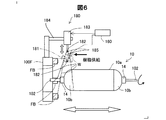
次に、フープ巻きユニット100Fにおいて改めて樹脂含浸を行う樹脂含浸ユニット180の構成と当該ユニットによる樹脂含浸カーボン繊維束Wの熱硬化性樹脂含浸について説明する。図6は樹脂含浸ユニット180の構成と樹脂含浸の様子を側面視して概略的に示す説明図である。
Next, the structure of the
図示するように、フープ巻きユニット100Fは、フープ巻きの巻回軌跡で樹脂含浸カーボン繊維束Wをライナー10に巻回するに当たり、個々のフープ巻き用繊維ボビンFBからくり出した複数筋の樹脂含浸カーボン繊維束Wを、案内ローラー群181にて集め一筋の樹脂含浸カーボン繊維束Wとする。樹脂含浸ユニット180は、案内ローラー群181にて一筋とされた樹脂含浸カーボン繊維束Wに対して熱硬化性樹脂含浸を図るべく、ピックアップローラー182と、ローラー上下動機構183と、保持脚184と、繊維束クランプ185とを備える。
As shown in the figure, the
ピックアップローラー182は、保持脚184にてフープ巻きユニット100Fのフレームに固定されたローラー上下動機構183のシリンダーシャフト先端に配設されている。このピックアップローラー182は、案内ローラー群181にて一筋とされた樹脂含浸カーボン繊維束Wの下方まで、ローラー上下動機構183にて降下する。この際、ローラー上下動機構183は、ピックアップローラー182を、樹脂含浸カーボン繊維束Wと干渉させないようにして降下させる。その後、ローラー上下動機構183は、ピックアップローラー182を元の位置に後退させることで、複数筋の樹脂含浸カーボン繊維束Wを一筋の状態で案内ローラー群181から持ち上げる。
The
繊維束クランプ185は、図6の紙面における奥側と手前側に前後動可能とされ、ピックアップローラー182にて持ち上げた一筋の樹脂含浸カーボン繊維束Wを、紙面における奥側から手前側に前進して把持する。この繊維束クランプ185は、多孔質のスポンジ状とされた上で、図示しない樹脂供給装置から、樹脂含浸カーボン繊維束Wに含浸した熱硬化性樹脂(例えばエポキシ樹脂等)と同質の熱硬化性樹脂の溶液の供給を受けている。よって、樹脂含浸ユニット180は、繊維束クランプ185で把持した樹脂含浸カーボン繊維束Wに熱硬化性樹脂を改めて含浸させると共に、把持力と樹脂溶液供給量を調整することで、樹脂含浸量についても調整する。樹脂含浸ユニット180による上記した熱硬化性樹脂の含浸は、後述のタイミングでなされ、その際には、ライナー10は回転を停止している。そして、樹脂含浸ユニット180による樹脂含浸の後、樹脂含浸カーボン繊維束Wは、樹脂含浸ユニット180が有する繊維カッターにて切断され、その後のライナー10の回転により引き出されて、ライナー10に巻回される。
The
次に、ヘリカル巻きユニット100Hとフープ巻きユニット100Fとを有するFW装置100を用いた高圧ガスタンクTの製造工程について説明する。図7は高圧ガスタンクTの製造工程を示す手順図、図8は高圧ガスタンクTにおける繊維強化樹脂層20の内外の樹脂層部位を樹脂含浸カーボン繊維束Wの巻回の様子と合わせて示す説明図である。
Next, the manufacturing process of the high-pressure gas tank T using the
図7に示すように、高圧ガスタンクTを製造するに当たり、まず、ライナー10を支持台310(図2参照)に装着する(ステップS100)。制御装置160は、支持台310の駆動機器を制御してライナー10を所定の一定の回転速度で回転制御し、定速回転となると、ライナー10をタンク中心軸AXに沿って往復動しつつ、ヘリカル巻きユニット100Hの繊維束案内体210から樹脂含浸カーボン繊維束Wを送り出し、図3(A)に示すように、低角度のヘリカル巻きを複数の層となるよう繰り返す(ステップS110)。これにより、ライナー10の外表面には、複数層の最内層の低角度ヘリカル層20Hが形成される。図8では、この低角度ヘリカル層20Hを一つの層と擬製して表している。なお、ライナー10の回転速度とタンク中心軸AXに沿った往復動速度は、低角度のヘリカル巻きに即した速度に調整される。
As shown in FIG. 7, in manufacturing the high-pressure gas tank T, first, the
制御装置160は、低角度のヘリカル巻きを開始してからの経過時間やライナー10の回転速度・往復速度等に基づいて、低角度ヘリカル層20Hの形成のための樹脂含浸カーボン繊維束Wのヘリカル巻きの終了タイミングに達したか否かを判定する(ステップS120)。ここで肯定判定されるまで、ステップS110のヘリカル巻きが継続される。制御装置160は、ステップS120にて肯定判定すると、熱硬化性樹脂の含浸量増大調整を行う(ステップS130)。制御装置160は、この含浸量増大調整において、図5に示した繊維束押圧ローラー158を最下段まで降下させる。これにより、樹脂含浸カーボン繊維束Wは、プリプレグである故に樹脂含浸済みであるが、改めて熱硬化性樹脂の含浸を受けるので、ヘリカル巻きの巻回終了タイミングでライナー10に巻回される繊維束末端領域において、樹脂含浸量が増大する。そして、含浸量が増大した状態の繊維束末端領域の樹脂含浸カーボン繊維束Wは、ライナー10にヘリカル巻きされた上で、図示しないカッティング機器、或いは作業者にて切断される。もしくは、樹脂含浸カーボン繊維束Wは、繊維束末端領域にてライナー10にヘリカル巻きされたまま更に送り出され、ライナー10の側方まで延びて、次回のヘリカル巻きに備える。
The
本実施形態では、ヘリカル巻きの巻回終了タイミングでの樹脂含浸量の増大調整に加え、ヘリカル巻きの継続中においても、次のようにして、繊維束樹脂含浸分配ユニット150にて樹脂含浸量を調整する。図8に示すように、低角度ヘリカル層20Hは、ライナー10の外表面の側から複数形成される。本実施形態では、ライナー10の外表面に近い内層側の低角度ヘリカル層20Hと外層側の低角度ヘリカル層20Hとで、樹脂含浸カーボン繊維束Wの樹脂含浸量を調整した。制御装置160は、図8に示す5層の低角度ヘリカル層20Hのうちで内層側の3層の低角度ヘリカル層20Hの形成の際には、図5に実線で示すように、繊維束押圧ローラー158をストローク途中まで降下させる。これにより、内層側の3層の低角度ヘリカル層20Hでは、樹脂含浸カーボン繊維束Wの樹脂含浸量は、ヘリカル巻きの巻回終了タイミングでの樹脂含浸量より少ないとは言え、増大調整される。その一方、制御装置160は、図8に示す5層の低角度ヘリカル層20Hのうちで外層側の2層の低角度ヘリカル層20Hの形成の際には、繊維束押圧ローラー158を貯留樹脂溶液Rの液面より上に退避させる。これにより、外層側の2層の低角度ヘリカル層20Hでは、樹脂含浸カーボン繊維束Wの樹脂含浸量は、プリプレグの際の樹脂含浸量のままとなる。よって、内層側の低角度ヘリカル層20Hの形成の際のヘリカル巻きでは、外層側の低角度ヘリカル層20Hの形成の際のヘリカル巻きの場合より、樹脂含浸量が多く調整されて、樹脂含浸カーボン繊維束Wがライナー10にヘリカル巻きされる。
In the present embodiment, in addition to the increase adjustment of the resin impregnation amount at the winding end timing of the helical winding, the resin bundle impregnation amount is adjusted by the fiber bundle resin impregnation /
制御装置160は、上記したヘリカル巻きに続き、ライナー10の回転速度と往復動速度とを高角度のフープ巻きに即した速度に調整した上で、フープ巻きユニット100Fの案内ローラー群181(図6参照)から樹脂含浸カーボン繊維束Wを一筋の状態で送り出し、図3(B)に示すように、高角度のフープ巻きを複数の層となるよう繰り返す(ステップS140)。これにより、ライナー10の外表面には、最内層の低角度ヘリカル層20Hに重ねて複数層の高角度フープ層20Fが形成される。図8では、この高角度フープ層20Fについても一つの層と擬製して表している。
After the helical winding described above, the
制御装置160は、高角度のフープ巻きを開始してからの経過時間やライナー10の回転速度・往復速度等に基づいて、高角度フープ層20Fの形成のための樹脂含浸カーボン繊維束Wのフープ巻きの終了タイミングに達したか否かを判定する(ステップS150)。ここで肯定判定されるまで、ステップS140のフープ巻きが継続される。制御装置160は、ステップS150にて肯定判定すると、熱硬化性樹脂の含浸量増大調整を行う(ステップS160)。制御装置160は、この含浸量増大調整において、図6に示したピックアップローラー182にて一筋の樹脂含浸カーボン繊維束Wを持ち上げた上で、繊維束クランプ185にて樹脂含浸カーボン繊維束Wに改めて熱硬化性樹脂を含浸させ、フープ巻きの巻回終了タイミングでライナー10に巻回される繊維束末端領域において、樹脂含浸量を増大させる。このフープ巻きの巻回終了タイミングでの樹脂含浸量は、その含浸が繊維束クランプ185による把持であることから、上記のヘリカル巻きの終了タイミングでの貯留樹脂溶液Rへの浸漬を経た樹脂含浸量より少なくなる。そして、含浸量が増大した状態の繊維束末端領域の樹脂含浸カーボン繊維束Wは、樹脂含浸ユニット180が有する繊維カッターにて切断され、その後のライナー10の回転により引き出されて、ライナー10にフープ巻回される。もしくは、樹脂含浸カーボン繊維束Wは、繊維束末端領域にてライナー10にフープ巻きされたまま更に送り出され、ライナー10の側方まで延びて、次回のフープ巻きに備える。
Based on the elapsed time since the start of the high-angle hoop winding, the rotational speed / reciprocating speed of the
制御装置160は、上記したヘリカル巻きとフープ巻きとの繰り返しが完了したか否かを判定し(ステップS170)、肯定判定するまで、上記したヘリカル巻きとフープ巻きとを使い分けて繰り返す。よって、図8に示すように、ライナー10の外表面の繊維強化樹脂層20は、ライナー10の外周側から、ヘリカル巻きによる樹脂含浸カーボン繊維束Wの低角度ヘリカル層20Hとフープ巻きによる樹脂含浸カーボン繊維束Wの高角度フープ層20Fとが交互に積層されて形成される。図においては、図示の都合から、各樹脂層部位は単一の樹脂含浸カーボン繊維束Wを含むようにされているが、各樹脂層では、既述したようにフープ巻きとヘリカル巻きでの樹脂含浸カーボン繊維束Wの複数回の巻回により、複数の樹脂含浸カーボン繊維束Wがフープ巻きとヘリカル巻きで重なることになる。なお、図8では、タンク中心軸AXを含んでタンクを長手方向に断面視していることから、繊維の配向がフープ巻きに基づいた約89°の高角度フープ層20Fでは、樹脂含浸カーボン繊維束Wは繊維と交差するよう切断したほぼ円形に断面視される。その一方、繊維の配向が低角度のヘリカル巻きに基づいた約11〜25°の低角度ヘリカル層20Hでは、樹脂含浸カーボン繊維束Wは繊維長手方向に沿って切断した矩形状に断面視される。
The
制御装置160は、上記したヘリカル巻きとフープ巻きとの繰り返しが完了したと肯定判定すると、ライナー10の回転を停止した上で、ライナー10をヘリカル巻きユニット100Hおよびフープ巻きユニット100Fと干渉しない位置に移動させる。これにより、ライナー10は、FW装置100から取り外され、図示しない加熱装置にて、熱硬化性樹脂の加熱硬化処理に処され、冷却養生を経ることで、ライナー10を繊維強化樹脂層20で補強被覆した高圧ガスタンクTが得られる。
When the
以上説明したように、本実施形態のFW装置100は、ヘリカル巻きユニット100Hによる樹脂含浸カーボン繊維束Wのヘリカル巻きの巻回終了タイミングで(ステップS130)、並びに、フープ巻きユニット100Fによる樹脂含浸カーボン繊維束Wのフープ巻きの巻回終了タイミングで(ステップS160)、ライナー10に巻回される樹脂含浸カーボン繊維束Wの繊維束末端領域を、熱硬化性樹脂の含浸量が増大調整された状態とする。よって、本実施形態のFW装置100によれば、増大含浸量の熱硬化性樹脂にて、ヘリカル巻きの際の繊維束末端領域、並びに、フープ巻きの際の繊維束末端領域を、巻回済みのヘリカル巻回の繊維束或いは巻回済みのフープ巻きの繊維束に、それぞれ容易に仮止めできる。また、本実施形態のFW装置100によれば、増大含浸量の熱硬化性樹脂の熱硬化により、巻回済みの繊維束に固定できる。この結果、本実施形態のFW装置100によれば、樹脂含浸カーボン繊維束Wの繊維束末端領域の固定に特化した他の部材が不要となると共に、樹脂含浸カーボン繊維束Wを硬化・固定するための熱硬化性樹脂の熱硬化処理についても一度で済むので、タンク製造工程の簡略化を図ることができる。また、上記の他の部材が不要なことから、当該部材の繊維束への装着も無用となるので、コスト低減に寄与できる。
As described above, the
本実施形態のFW装置100は、ヘリカル巻きユニット100Hによる樹脂含浸カーボン繊維束Wのヘリカル巻きの巻回終了タイミングでの樹脂含浸量を(ステップS130)、フープ巻きユニット100Fによる樹脂含浸カーボン繊維束Wのフープ巻きの巻回終了タイミングでの樹脂含浸量(ステップS160)より多くした。よって、次の利点がある。図3に示すように、ヘリカル巻きユニット100Hによるヘリカル巻きでは、樹脂含浸カーボン繊維束Wの巻回軌跡が繊維巻回対象物の中心軸に対して低角度の繊維角(例えば、約11〜25°)で交差し、フープ巻きユニット100Fによるフープ巻きでは中心軸に対してほぼ垂直に近い繊維角(例えば約89°)で交差する。よって、ヘリカル巻きされる樹脂含浸カーボン繊維束Wは、フープ巻きの場合より、一般にライナー10の表面から滑りやすくなる。ところが、本実施形態のFW装置100では、上記のように滑りやすいヘリカル巻きの樹脂含浸カーボン繊維束Wの繊維束末端領域を、フープ巻きの場合より熱硬化性樹脂の含浸量が増大調整された状態とするので、滑りやすいヘリカル巻きの繊維束末端領域を、巻回済みのヘリカル巻回の樹脂含浸カーボン繊維束Wに、増大含浸させた熱硬化性樹脂により容易、且つ確実に仮止めできる。その上で、増大含浸させた熱硬化性樹脂の熱硬化により、ヘリカル巻きで巻回済みの樹脂含浸カーボン繊維束Wにより確実に固定できる。この結果、本実施形態のFW装置100によれば、樹脂含浸カーボン繊維束Wのヘリカル巻きおよびフープ巻きを経て得られる最終製品たる高圧ガスタンクTにおいて、ヘリカル巻き繊維束のズレが抑制されることから、タンク強度を高めることができる。
The
本実施形態のFW装置100では、ヘリカル巻きユニット100Hによるヘリカル巻きとフープ巻きユニット100Fによるフープ巻きとを繰り返すことで、低角度ヘリカル層20Hと高角度フープ層20Fとを交互にライナー10に積層形成した。その上で、内層側の低角度ヘリカル層20Hの形成のためのヘリカル巻きユニット100Hによるヘリカル巻きの際には、繊維束樹脂含浸分配ユニット150にて改めて熱硬化性樹脂を樹脂含浸カーボン繊維束Wに含浸させ、その含浸量を、外層側の低角度ヘリカル層20Hの形成のためのヘリカル巻きの場合より多くした。この結果、本実施形態のFW装置100によれば、内層側に形成された低角度ヘリカル層20Hに多く含浸されていた熱硬化性樹脂を、外層側に形成される低角度ヘリカル層20Hに染み渡るようにできるので、内層側の低角度ヘリカル層20Hに含浸した熱硬化性樹脂を有効利用できる。
In the
本発明は、上述の実施形態に限られるものではなく、その趣旨を逸脱しない範囲において種々の構成で実現することができる。例えば、発明の概要の欄に記載した各形態中の技術的特徴に対応する実施形態の技術的特徴は、上述の課題の一部又は全部を解決するために、或いは、上述の効果の一部又は全部を達成するために、適宜、差し替えや、組み合わせを行うことが可能である。また、その技術的特徴が本明細書中に必須なものとして説明されていなければ、適宜、削除することが可能である。 The present invention is not limited to the above-described embodiment, and can be realized with various configurations without departing from the spirit of the present invention. For example, the technical features of the embodiments corresponding to the technical features in each embodiment described in the summary section of the invention are intended to solve part or all of the above-described problems, or part of the above-described effects. Or, in order to achieve the whole, it is possible to replace or combine as appropriate. Further, if the technical feature is not described as essential in the present specification, it can be deleted as appropriate.
本実施形態では、高圧ガスタンクのコア材であるライナー10を繊維巻回対象物としたが、ライナー以外の繊維巻回対象物に繊維を巻回するようにしてもよい。また、本実施形態では、ボビンユニット120における繊維ボビンBに樹脂含浸カーボン繊維束Wを巻き取り済みとしたが、熱硬化性樹脂の未含浸のカーボン繊維束を巻き取るようにしてもよい。この場合には、繊維束樹脂含浸分配ユニット150から繊維束案内体210に樹脂未含浸のカーボン繊維束を供給する際に、この繊維束樹脂含浸分配ユニット150にて熱硬化性樹脂を含浸して、樹脂含浸カーボン繊維束Wとすればよい。具体的には、樹脂未含浸のカーボン繊維束のヘリカル巻きの当初から、繊維束押圧ローラー158を、その案内するカーボン繊維束が樹脂溶液槽151の貯留樹脂溶液Rに浸漬するように降下させ、これにより、樹脂含浸カーボン繊維束Wとする。そして、樹脂溶液槽151にて樹脂含浸を図った樹脂含浸カーボン繊維束Wを、既述したように、繊維束樹脂含浸分配ユニット150からそれぞれの繊維束案内体210に供給すればよい。この際、ヘリカル巻きの終了タイミングでの既述した樹脂含浸量の増大調整を行うことができるほか、内外層のヘリカル層形成の際の樹脂含浸量の増大調整も併用できる。
In the present embodiment, the
本実施形態では、フープ巻きユニット100Fとヘリカル巻きユニット100Hとを有するFW装置100において、クリルスタンド110からヘリカル巻きユニット100Hに樹脂含浸カーボン繊維束Wを供給したが、ヘリカル巻きユニット100Hのみを有するFW装置100に適用できる。
In the present embodiment, in the
10…ライナー
10a…シリンダー部
10b…ドーム部
14…口金
20…繊維強化樹脂層
20F…高角度フープ層
20H…低角度ヘリカル層
100…FW装置
100F…フープ巻きユニット
100H…ヘリカル巻きユニット
102…ライナー軸支シャフト
110…クリルスタンド
120…ボビンユニット
150…繊維束樹脂含浸分配ユニット
151…樹脂溶液槽
152…上流側第1案内ローラー
153…上流側第2案内ローラー
154…下流側第1案内ローラー
155…下流側第2案内ローラー
156…仕切保持枠
157…仕切
158…繊維束押圧ローラー
159…シリンダー機構
160…制御装置
180…樹脂含浸ユニット
181…案内ローラー群
182…ピックアップローラー
183…ローラー上下動機構
184…保持脚
185…繊維束クランプ
202…繊維束案内フレーム
204…固定フレーム
210…繊維束案内体
300…基台
302…第1レール
304…第2レール
310…支持台
312…ベース
314…支持腕
316…チャック
W…樹脂含浸カーボン繊維束
B…繊維ボビン
FB…フープ巻き用繊維ボビン
R…貯留樹脂溶液
T…高圧ガスタンク
AX…タンク中心軸
DESCRIPTION OF
Claims (3)
前記繊維束を巻き取り済みの繊維ボビンを、前記繊維束を送り出し可能に保持するボビンユニットと、
前記繊維巻回対象物の軸芯に沿って相対的に往復動し、供給を受けた前記繊維束を前記往復動の過程で前記繊維巻回対象物の外表面に巻回する繊維巻回部と、
該繊維巻回部により前記繊維巻回対象物に巻回される前記繊維束を熱硬化性樹脂溶液に接触させ、該熱硬化性樹脂溶液との接触状態を制御して前記繊維束への前記熱硬化性樹脂溶液の含浸量を調整する含浸調整部とを備え、
該含浸調整部は、前記繊維巻回部による前記繊維束の巻回終了タイミングで前記繊維巻回対象物に巻回される繊維束末端領域において、前記含浸量を増大調整する
フィラメントワインディング装置。 A filament winding apparatus for winding a large number of fibers around a fiber winding object in the form of a fiber bundle,
A bobbin unit for holding the fiber bobbin from which the fiber bundle has been wound, so that the fiber bundle can be sent out;
A fiber winding part that reciprocates relatively along the axis of the fiber winding object and winds the supplied fiber bundle around the outer surface of the fiber winding object in the process of reciprocation When,
The fiber bundle wound around the fiber 維巻times object by the fiber winding portion is brought into contact with the thermosetting resin solution, by controlling the contact state between the thermosetting resin solution to said fiber bundle An impregnation adjusting unit for adjusting the amount of impregnation of the thermosetting resin solution,
Impregnation adjusting section in the fiber bundle end region in the winding end timing of the fiber bundle by fiber winding portion wound around the fiber 維巻times the object, a filament winding apparatus for increasing adjusting the amount of impregnation.
前記繊維巻回部として、前記繊維巻回対象物に繊維束をフープ巻きするフープ巻部と、前記繊維巻回対象物に繊維束をヘリカル巻きするヘリカル巻部とを備え、
前記含浸調整部は、前記ヘリカル巻部での前記繊維束末端領域における前記含浸量を、前記フープ巻部での前記繊維束末端領域における前記含浸量より多く調整する
フィラメントワインディング装置。 The filament winding apparatus according to claim 1,
As the fiber winding part, a hoop winding part that hoops a fiber bundle around the fiber winding object, and a helical winding part that helically winds a fiber bundle around the fiber winding object,
The impregnation adjusting unit adjusts the impregnation amount in the fiber bundle end region in the helical winding unit to be larger than the impregnation amount in the fiber bundle end region in the hoop winding unit.
前記ヘリカル巻部によるヘリカル巻きと前記フープ巻部によるフープ巻きとを繰り返し、ヘリカル層とフープ層とを交互に前記繊維巻回対象物に積層形成し、
前記含浸調整部は、前記繊維束末端領域における前記含浸量の調整に加え、内層側のヘリカル層の形成のための前記ヘリカル巻部によるヘリカル巻きの際には、外層側のヘリカル層の形成のための前記ヘリカル巻部によるヘリカル巻きの場合より前記含浸量を多く調整する
フィラメントワインディング装置。 The filament winding apparatus according to claim 2,
Helical winding by the helical winding portion and hoop winding by the hoop winding portion are repeated, and a helical layer and a hoop layer are alternately laminated on the fiber winding object,
In addition to adjusting the amount of impregnation in the fiber bundle end region, the impregnation adjusting unit is configured to form a helical layer on the outer layer side during helical winding by the helical winding unit for forming the helical layer on the inner layer side. A filament winding apparatus that adjusts the amount of impregnation more than in the case of helical winding by the helical winding portion.
Priority Applications (1)
| Application Number | Priority Date | Filing Date | Title |
|---|---|---|---|
| JP2013127180A JP5937546B2 (en) | 2013-06-18 | 2013-06-18 | Filament winding equipment |
Applications Claiming Priority (1)
| Application Number | Priority Date | Filing Date | Title |
|---|---|---|---|
| JP2013127180A JP5937546B2 (en) | 2013-06-18 | 2013-06-18 | Filament winding equipment |
Publications (3)
| Publication Number | Publication Date |
|---|---|
| JP2015000554A JP2015000554A (en) | 2015-01-05 |
| JP2015000554A5 JP2015000554A5 (en) | 2015-11-12 |
| JP5937546B2 true JP5937546B2 (en) | 2016-06-22 |
Family
ID=52295369
Family Applications (1)
| Application Number | Title | Priority Date | Filing Date |
|---|---|---|---|
| JP2013127180A Active JP5937546B2 (en) | 2013-06-18 | 2013-06-18 | Filament winding equipment |
Country Status (1)
| Country | Link |
|---|---|
| JP (1) | JP5937546B2 (en) |
Families Citing this family (3)
| Publication number | Priority date | Publication date | Assignee | Title |
|---|---|---|---|---|
| JP7078905B2 (en) | 2019-01-16 | 2022-06-01 | トヨタ自動車株式会社 | Manufacturing method of high pressure tank |
| JP2023534749A (en) * | 2020-07-22 | 2023-08-10 | ビーエーエスエフ ソシエタス・ヨーロピア | Equipment and process for producing composite parts containing at least one wound fiber-reinforced polymer layer |
| CN115139585B (en) * | 2022-06-23 | 2024-01-12 | 红豆集团无锡红豆童装有限公司 | Skin-friendly fabric for children's garments and preparation process thereof |
Family Cites Families (5)
| Publication number | Priority date | Publication date | Assignee | Title |
|---|---|---|---|---|
| JP2007185827A (en) * | 2006-01-12 | 2007-07-26 | Toyota Motor Corp | Filament winding apparatus |
| JP2008296411A (en) * | 2007-05-30 | 2008-12-11 | Toyota Motor Corp | Method and device for manufacturing fiber reinforced resin container |
| JP2009051186A (en) * | 2007-08-29 | 2009-03-12 | Toyota Motor Corp | Method of manufacturing molded product, and molded product manufacturing system |
| JP5218889B2 (en) * | 2008-02-13 | 2013-06-26 | トヨタ自動車株式会社 | Tank manufacturing method and retaining member |
| JP5656752B2 (en) * | 2011-06-10 | 2015-01-21 | トヨタ自動車株式会社 | Filament winding method, filament winding apparatus and tank |
-
2013
- 2013-06-18 JP JP2013127180A patent/JP5937546B2/en active Active
Also Published As
| Publication number | Publication date |
|---|---|
| JP2015000554A (en) | 2015-01-05 |
Similar Documents
| Publication | Publication Date | Title |
|---|---|---|
| JP5531040B2 (en) | Manufacturing method of high-pressure gas tank | |
| EP2591907B1 (en) | Filament winding apparatus | |
| US6736168B2 (en) | Fiber reinforced plastic pipe and filament winding apparatus | |
| JP4273092B2 (en) | Prepreg manufacturing method and prepreg manufacturing apparatus | |
| JP5937546B2 (en) | Filament winding equipment | |
| KR20150058451A (en) | Hoop winding device, filament winding device, and tank production method | |
| JP7078905B2 (en) | Manufacturing method of high pressure tank | |
| JP2015000553A (en) | Filament winding device | |
| JP2018130839A (en) | Roving tension imparting mechanism in filament winding apparatus | |
| JP2011136491A (en) | Process of producing composite container | |
| JP5737047B2 (en) | High pressure gas tank manufacturing method and manufacturing apparatus | |
| JP6337398B2 (en) | Manufacturing method of composite container and composite container | |
| JP5796508B2 (en) | Induction heating method and apparatus, and high pressure gas tank manufacturing method | |
| JP2013161610A (en) | Induction heating apparatus, and method of manufacturing high-pressure gas tank | |
| JP5986038B2 (en) | Filament winding equipment | |
| JP2004148776A (en) | Filament winding apparatus | |
| JP2005154908A (en) | Yarn-feeding unit for filament winding apparatus, filament winding apparatus and method for producing structure | |
| JP2004188869A (en) | Filament bundle pulling-out device in filament winding apparatus | |
| JP2020020420A (en) | Manufacturing method of tank | |
| KR20170113031A (en) | Apparatus for manufacturing composite rebar for concrete | |
| JP2020044793A (en) | Method for manufacturing tank | |
| JP2009028961A (en) | Manufacturing process and manufacturing system of frp molding | |
| JP5687979B2 (en) | Filament winding method and filament winding apparatus | |
| JP6939538B2 (en) | How to make a tank | |
| JP2011005660A (en) | Filament winding method |
Legal Events
| Date | Code | Title | Description |
|---|---|---|---|
| A621 | Written request for application examination |
Free format text: JAPANESE INTERMEDIATE CODE: A621 Effective date: 20150820 |
|
| A521 | Request for written amendment filed |
Free format text: JAPANESE INTERMEDIATE CODE: A523 Effective date: 20150928 |
|
| A977 | Report on retrieval |
Free format text: JAPANESE INTERMEDIATE CODE: A971007 Effective date: 20160413 |
|
| TRDD | Decision of grant or rejection written | ||
| A01 | Written decision to grant a patent or to grant a registration (utility model) |
Free format text: JAPANESE INTERMEDIATE CODE: A01 Effective date: 20160419 |
|
| A61 | First payment of annual fees (during grant procedure) |
Free format text: JAPANESE INTERMEDIATE CODE: A61 Effective date: 20160512 |
|
| R151 | Written notification of patent or utility model registration |
Ref document number: 5937546 Country of ref document: JP Free format text: JAPANESE INTERMEDIATE CODE: R151 |
|
| R250 | Receipt of annual fees |
Free format text: JAPANESE INTERMEDIATE CODE: R250 |
|
| R250 | Receipt of annual fees |
Free format text: JAPANESE INTERMEDIATE CODE: R250 |
|
| R250 | Receipt of annual fees |
Free format text: JAPANESE INTERMEDIATE CODE: R250 |
|
| R250 | Receipt of annual fees |
Free format text: JAPANESE INTERMEDIATE CODE: R250 |
|
| R250 | Receipt of annual fees |
Free format text: JAPANESE INTERMEDIATE CODE: R250 |
|
| R250 | Receipt of annual fees |
Free format text: JAPANESE INTERMEDIATE CODE: R250 |