JP5936737B2 - Sheet conveying apparatus, image forming apparatus, and image reading apparatus - Google Patents
Sheet conveying apparatus, image forming apparatus, and image reading apparatus Download PDFInfo
- Publication number
- JP5936737B2 JP5936737B2 JP2015078073A JP2015078073A JP5936737B2 JP 5936737 B2 JP5936737 B2 JP 5936737B2 JP 2015078073 A JP2015078073 A JP 2015078073A JP 2015078073 A JP2015078073 A JP 2015078073A JP 5936737 B2 JP5936737 B2 JP 5936737B2
- Authority
- JP
- Japan
- Prior art keywords
- sheet
- light
- sheet conveying
- path
- light receiving
- Prior art date
- Legal status (The legal status is an assumption and is not a legal conclusion. Google has not performed a legal analysis and makes no representation as to the accuracy of the status listed.)
- Expired - Fee Related
Links
Images


Description
本発明は、シート搬送装置、画像形成装置及び画像読取装置に関し、特に湾曲したシート搬送路を通過するシートを検知するセンサの構成に関する。 The present invention relates to a sheet conveying apparatus, an image forming apparatus, and an image reading apparatus, and more particularly to a configuration of a sensor that detects a sheet passing through a curved sheet conveying path.
近年、複写機、プリンタ、ファクシミリ等の画像形成装置及びスキャナ等の画像読取装置においては、画像形成動作及び画像読取動作の高速化・高精度化の要望がある。これに伴い、画像形成装置及び画像読取装置に設けられた、記録媒体や原稿等のシートを搬送するシート搬送装置においても、高速化、高精度化が求められている。 In recent years, image forming apparatuses such as copying machines, printers, facsimiles, and image reading apparatuses such as scanners have been demanded to increase the speed and accuracy of image forming operations and image reading operations. Along with this, high speed and high accuracy are also demanded in the sheet conveying apparatus provided in the image forming apparatus and the image reading apparatus for conveying sheets such as recording media and originals.
ところで、従来、シート搬送装置は、シートが通過するシート搬送路を備えており、このシート搬送路にはシートの通過を検知するセンサが多数設けられている。ここで、このようなセンサとしては、フォトインタラプタとメカニカルなフラグを備えた安価なセンサを用いるのが一般的である(特許文献1参照)。しかし、このような構成のセンサでは、シートがフラグに衝突する際のショックでチャタリングを起こしやすく、高速化には不向きであった。 By the way, conventionally, a sheet conveying apparatus includes a sheet conveying path through which a sheet passes, and a number of sensors for detecting the passage of the sheet are provided in the sheet conveying path. Here, as such a sensor, an inexpensive sensor having a photo interrupter and a mechanical flag is generally used (see Patent Document 1). However, in the sensor having such a configuration, chattering is likely to occur due to a shock when the sheet collides with the flag, and is not suitable for speeding up.
そこで、このようなセンサの代わりにシートに対して光を照射する光源と、光源に並べて配置された受光素子と、受光素子と対向する位置に配置されたプリズムを備えた光学式の透過型センサが用いられることがある(特許文献2参照)。 Therefore, instead of such a sensor, an optical transmission type sensor including a light source for irradiating light to the sheet, a light receiving element arranged in line with the light source, and a prism disposed at a position facing the light receiving element. May be used (see Patent Document 2).
このような透過型センサの場合、受光素子は、プリズムとの間にシートがない時は、プリズムから反射した光を検出するが、シートがあるときは光が遮られて光を検出しない。このため、プリズムから反射した光を受光素子が検出するか否かにより、シートの有無を検出することができる。しかし、このようなシートが光を遮ることを利用する透過型方式のセンサでは、シートがOHPシート等の光を透過してしまうシートの場合には、シートを検知することができない。 In the case of such a transmissive sensor, the light receiving element detects light reflected from the prism when there is no sheet between the prism, but when there is a sheet, the light is blocked and does not detect light. For this reason, the presence or absence of the sheet can be detected based on whether or not the light receiving element detects the light reflected from the prism. However, in such a transmission type sensor that utilizes light blocking by a sheet, when the sheet is a sheet that transmits light, such as an OHP sheet, the sheet cannot be detected.
一方、他の光学式のセンサとして、光源と、光源に並べて配置された受光素子を備え、光源からシート搬送路を通過するシートに光を照射し、シートに当たって反射した光を受光素子により受光する反射型のセンサがある。そして、この様な構成の反射型のセンサの場合、透過型のセンサと異なりOHPシート等の光を透過してしまうシートも検知することができる。 On the other hand, as another optical sensor, a light source and a light receiving element arranged side by side with the light source are provided. Light is emitted from the light source to the sheet passing through the sheet conveyance path, and light reflected by the sheet is received by the light receiving element. There is a reflective sensor. In the case of a reflective sensor having such a configuration, a sheet that transmits light, such as an OHP sheet, can be detected unlike a transmissive sensor.
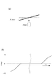
ところで、従来のシート搬送装置において、屈曲しているシート搬送路を備えたものがある。そして、このような屈曲しているシート搬送路に透過型のセンサを配置すると、シート搬送路を通過する際、シートは、光源からの照射光に対して角度がついた状態で搬送されるようになる。ここで、反射型のセンサの場合、照射光に対して角度がついた状態でシートが搬送されると、特にOHPシートのような乱反射の少ないシートでは、後述する図2の(b)に示すように、シートからの反射光を受光素子が検知しにくくなる。 Incidentally, some conventional sheet conveying apparatuses include a bent sheet conveying path. When a transmissive sensor is arranged in such a bent sheet conveyance path, the sheet is conveyed in an angled state with respect to the irradiation light from the light source when passing through the sheet conveyance path. become. Here, in the case of a reflection type sensor, when the sheet is conveyed with an angle with respect to the irradiation light, particularly in a sheet with little irregular reflection such as an OHP sheet, as shown in FIG. Thus, it becomes difficult for the light receiving element to detect the reflected light from the sheet.
そこで、このように角度のついたOHPシートを検知しやすくするには、例えば照射光を拡散させたり、照度を上げたりする必要がある。しかし、照射光を拡散させたり、照度を上げたりすると、シートではなく、シート搬送路を形成する通路部材に光が当たって反射し、この反射した光を受光素子が検知して誤検知する懸念がある。 Thus, in order to easily detect such an angled OHP sheet, for example, it is necessary to diffuse irradiation light or increase illuminance. However, if the irradiating light is diffused or the illuminance is increased, the light hits and reflects not the sheet but the path member forming the sheet conveying path, and the light receiving element may detect the reflected light and erroneously detect it. There is.
したがって、このような誤検知を回避するためには、すなわちシートを確実に検出するためには、例えば通路部材の拡散光が当たる部分に逃げ穴を設ける必要がある。しかし、このように逃げ穴を設けた場合、シートが高速で搬送される場合、シートが逃げ穴に引っ掛かってジャムするおそれがある。 Therefore, in order to avoid such erroneous detection, that is, in order to reliably detect the sheet, for example, it is necessary to provide a relief hole in a portion where the diffused light hits the passage member. However, when the escape hole is provided in this way, when the sheet is conveyed at a high speed, the sheet may be caught in the escape hole and jammed.
そこで本発明は、このような現状に鑑みてなされたものであり、屈曲したシート搬送路を高速で搬送されるシートを確実に検出することのできるシート搬送装置、画像形成装置及び画像読取装置を提供することを目的とするものである。 Accordingly, the present invention has been made in view of such a current situation, and provides a sheet conveying apparatus, an image forming apparatus, and an image reading apparatus that can reliably detect a sheet conveyed at a high speed along a bent sheet conveying path. It is intended to provide.
本発明は、シート搬送装置において、シート搬送方向に搬送されるシートが通過する、湾曲したシート搬送路と、シート搬送路内のシートを検知する検知ユニットと、を有し、前記検知ユニットは、前記シート搬送路へ向かう光を発する発光面と、前記シート搬送路のシートによって反射された反射光を受ける受光面と、を備え、前記発光面と前記受光面とは、前記シート搬送方向と直交する幅方向に並んでいて、前記受光面が受ける前記反射光の前記シート搬送方向における長さは、前記シート搬送方向に直交し且つ反射光が進む進行方向に直交する直交方向での長さよりも長いことを特徴とするものである。 The present invention provides a sheet conveying apparatus, the sheet passes through conveyed in the sheet conveying direction, has a curved sheet conveying path, a detection unit for detecting the sheet in the sheet conveying path, wherein the detection unit, a light emitting surface for emitting light toward the sheet conveying path, and a light-receiving surface accepted that the light reflected by the sheet of the sheet conveying path, wherein the light emitting surface and the light receiving surface, the sheet conveying direction The length of the reflected light received by the light receiving surface in the sheet conveying direction is perpendicular to the sheet conveying direction and is orthogonal to the traveling direction in which the reflected light travels. It is characterized by being longer than that .
本発明のように、光軸と垂直な断面におけるシート搬送方向における長さが、光軸と垂直な断面におけるシート搬送方向と直交する方向の長さよりも長い光を発光することにより、屈曲したシート搬送路を高速で搬送されるシートを確実に検出することができる。 As in the present invention, a sheet bent by emitting light whose length in the sheet conveyance direction in the cross section perpendicular to the optical axis is longer than the length in the direction perpendicular to the sheet conveyance direction in the cross section perpendicular to the optical axis. A sheet conveyed at high speed on the conveyance path can be reliably detected.
以下、本発明を実施する形態について、図面を用いて詳細に説明する。図1は、本発明の第1の実施の形態に係るシート搬送装置を備えた画像形成装置の概略構成を示す図である。図1において、100は画像形成装置、101は電子写真方式によりシート上に画像を形成する画像形成部、102はシート給送部である。ここで、画像形成部101には、感光体ドラム1、現像器4、レーザースキャナ3等が設けられている。また、シート給送部102にはシートSを収容するカセット5及びカセット5に収納されたシートを送り出す給送ローラR1が設けられている。
Hereinafter, embodiments of the present invention will be described in detail with reference to the drawings. FIG. 1 is a diagram illustrating a schematic configuration of an image forming apparatus including a sheet conveying device according to a first embodiment of the present invention. In FIG. 1, 100 is an image forming apparatus, 101 is an image forming unit that forms an image on a sheet by an electrophotographic method, and 102 is a sheet feeding unit. Here, the
次に、このような構成の画像形成装置100の動作について説明する。不図示の制御装置から画像信号がレーザースキャナ3に入力されると、レーザースキャナ3は画像信号に対応したレーザ光を矢印で示すように感光体ドラム1上に照射する。このとき感光体ドラム1は、予め帯電されおり、レーザ光が照射されることによって静電潜像が形成され、次いで静電潜像を現像器4によって現像することにより、感光体ドラム上にトナー像が形成される。
Next, the operation of the
一方、制御装置から給紙信号がシート給送部102に出力されると、給送ローラR1によりカセット5からシートSが給送される。この後、給送されたシートSは所定のタイミングで感光体ドラム1と転写帯電器6とにより構成される転写部に送られる。次に、このように転写部に送られたシートSは、転写部においてトナー像が転写され、この後、定着部8に搬送される。さらにこの後、定着部8によって加熱及び加圧されることにより、シートSに未定着転写画像が永久定着される。そして、このように画像が定着されたシートSは、搬送ローラR6及び排出ローラR7により排出される。
On the other hand, when a paper feed signal is output from the control device to the
なお、本実施の形態に係る画像形成装置100は両面画像形成機能及び反転排紙機能を有している。そして、反転排紙モードの場合は、定着部8を通過した後のシートSは、まず不図示の切換部材の切換えにより、分岐通路P1に導かれる。次に、搬送ローラR8,R9より反転ローラR10に搬送され、反転ローラR10の逆転と不図示の切換部材の切換えにより、シートは反転排出通路P2に送られ、この後、搬送ローラR15,R16より排出ローラR7に搬送されて排出される。
The
また、シートの両面に画像を形成する両面モードの場合には、定着部8による第1面の定着処理終了後のシートSは、まず分岐通路P1に導かれる。次に、反転ローラR10の逆転と、切換部材の切換えにより両面通路P3に搬送される。この後、両面通路P3に設けられた搬送ローラR11〜14によって搬送され、再びトナー像が転写、定着された後、搬送ローラR6及び排出ローラR7により排出される。
In the double-side mode in which images are formed on both sides of the sheet, the sheet S after the fixing process of the first surface by the
なお、図1において、103はシートを搬送するシート搬送装置であり、このシート搬送装置103は、既述した搬送ローラR6,R8〜R16の他、給送ローラR1により給送されたシートSを転写部に搬送する搬送ローラR2〜R5を備えている。また、このシート搬送装置103は、既述した分岐通路P1、反転排出通路P2、両面通路P3の他、給送ローラR1により給送されたシートSを転写部に搬送する搬送通路P4等からなるシート搬送路を有している。
In FIG. 1,
そして、このシート搬送路には、光反射型のセンサであるフォトセンサPS1〜19が配置されており、不図示に制御部は、このフォトセンサPS1〜19からの信号に基づいてシートSの通過タイミングを検出し、シート搬送制御を行っている。ここで、このフォトセンサPS1〜19として、図2に示すように、光源であるLED20を備えた発光部21と、受光素子30を備えた受光部31とを備えたものがある。
In the sheet conveying path, photosensors PS1 to 19 that are light reflection type sensors are arranged, and a control unit (not shown) passes the sheet S based on signals from the photosensors PS1 to PS19. Timing is detected and sheet conveyance control is performed. Here, as shown in FIG. 2, the photosensors PS <b> 1 to PS <b> 19 include a
なお、発光部21はLED20からの光を集光してシートSに向けて照射するための真円形状の発光レンズ22を備えている。また、受光部31は発光部21から照射された後、シートSから反射した光を集光して受光素子30に向かわせるための真円形状の受光レンズ32を備えている。
The
そして、このような構成のフォトセンサPSにおいては、LED20からの光を発光レンズ22により集光してシートSに向けて照射する。この後、シートSに当たって反射した反射光を受光レンズ32により集光し、この光を受光素子30が受光することにより、シートを検知する。
In the photosensor PS having such a configuration, the light from the
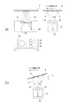
図3は、搬送通路P4の湾曲部分をシートSが通過する様子を示すものである。なお、この搬送通路P4の湾曲部分には、フォトセンサPS3が配置されている。図3の(a)は、搬送通路P4の湾曲部分にシートSの先端が進入しようとしている状態を示している。このとき、シートSはフォトセンサPS3の照射方向に対して傾いた状態で搬送されており、この場合、フォトセンサPS3からの照射光は、シートSに対して垂直でなく、斜めの方向から照射される。 FIG. 3 shows how the sheet S passes through the curved portion of the transport path P4. Note that a photosensor PS3 is disposed in a curved portion of the transport path P4. FIG. 3A shows a state where the leading edge of the sheet S is about to enter the curved portion of the conveyance path P4. At this time, the sheet S is conveyed in an inclined state with respect to the irradiation direction of the photosensor PS3. In this case, the irradiation light from the photosensor PS3 is not perpendicular to the sheet S but is irradiated from an oblique direction. Is done.
図3の(b)は、シートSが搬送通路P4の湾曲部分を通過している状態を示しており、このときフォトセンサPS3からの照射光は、シートSに対して垂直に照射されるようになる。また、図3の(c)はシートSの後端が搬送通路P4の湾曲部分を通過している状態を示しており、このときフォトセンサPS3からの照射光は、シートに対して垂直でなく、斜めの方向から照射される。 FIG. 3B shows a state in which the sheet S passes through the curved portion of the conveyance path P4. At this time, the irradiation light from the photosensor PS3 is irradiated perpendicularly to the sheet S. become. FIG. 3C shows a state in which the rear end of the sheet S passes through the curved portion of the conveyance path P4. At this time, the irradiation light from the photosensor PS3 is not perpendicular to the sheet. Irradiated from an oblique direction.
ここで、図4の(a)に示すようにシートSの、フォトセンサPS3からシートに向けて垂直に照射される光に対する傾きの角度をA(deg)としたとき、図3に示すようにシートSが搬送通路P4の湾曲部分を通過する場合、この角度Aは順次変わってしまう。例えば、この角度Aは、図4の(b)に示すように、シートSの搬送通路P4ほの進入初期においては−10deg程度であったが、搬送が進むにつれてほぼゼロになり、さらに進むと+10deg程度と、進入初期とは逆方向になる。 Here, as shown in FIG. 3, when the inclination angle of the sheet S with respect to the light irradiated perpendicularly from the photosensor PS3 toward the sheet is A (deg) as shown in FIG. When the sheet S passes through the curved portion of the conveyance path P4, the angle A changes sequentially. For example, as shown in FIG. 4B, the angle A was about −10 deg at the beginning of the entrance of the sheet S along the transport path P4. However, as the transport proceeds, the angle A becomes substantially zero. About +10 deg, it is in the opposite direction from the initial approach.
ところで、図2に示すフォトセンサPSのように、発光レンズ22が真円形状を有している場合、発光部21から発光された光のスポット光は図5の(a)に示すようにほぼ円形となる。しかし、このようにスポット光が円形の場合には、図2の(b)に示すように、シートがフォトセンサPSの照射方向に対して傾いた状態で搬送された場合、角度Aが大きくなると、シートSから反射した光はフォトセンサPSの受光レンズ33の方向に戻らなくなる。この場合、特に、シートSが反射率の高いシートの場合には、乱反射成分が少なく、検知しづらくなってしまうため、フォトセンサPSは、反射光を受光することができない。
By the way, when the
そこで、本実施の形態においては、少なくとも角度Aが大きくなる搬送通路P4の湾曲部分には、図6に示すように、発光レンズとして楕円形状の発光レンズ23を用い、受光レンズとして楕円形状の受光レンズ33を用いるフォトセンサセンサを配置している。ここで、発光レンズ23が楕円形状を有している場合、発光部21から発光された光のスポット光は図5の(b)に示すように楕円形となる。
Therefore, in the present embodiment, an elliptical
そして、本実施の形態においては、図5の(b)及び図7に示すようにフォトセンサPSの発光レンズ23及び受光レンズ33を、長辺がシート搬送方向に対して平行になる方向に配置している。ここで、このように楕円形状の発光レンズ23を用いた場合、図6の(b)に示すように、シート搬送方向に照射光が拡がるようになるため、シートSが傾いた状態でもシートSからの反射光Lのうち、一部の反射光L1が受光レンズ側へ戻るようになる。
In this embodiment, as shown in FIGS. 5B and 7, the light-emitting
このため、反射率の高いシートSが傾いた状態で搬送された場合でもシートSを確実に検出することができる。なお、このとき、受光レンズ33も楕円形状を有しているので、確実に反射光を受光することができる。このように、少なくとも発光レンズ23を楕円形状のレンズとすることにより、フォトセンサPSは、シートSがシート搬送方向に沿って傾斜した状態で搬送された場合でも反射光を受光することができる。
For this reason, even when the highly reflective sheet S is conveyed in an inclined state, the sheet S can be reliably detected. At this time, since the
以上説明したように、本実施の形態においては、楕円形状の発光レンズ23を用いることにより、発光部21の光を、シート搬送方向に沿って細長くした状態、言い換えればシート搬送方向に広げた状態でシートに向けて照射するようにするようにしている。これにより、発光部21からの光をシートに対してシート搬送方向に広い範囲で照射することができ、OHPシートのような乱反射の小さいシートに角度がついた状態でも確実に検知することができる。つまり、発光部21から光を、シート搬送方向に沿って広がった状態でシートSに向けて照射し、シートSからの反射光を受光部に向かわせるようにすることにより、屈曲したシート搬送路を高速で搬送されるシートを確実に検出することができる。
As described above, in the present embodiment, by using the elliptical
また、この場合、照射光の拡散を必要な方向、すなわちシート搬送方向にのみ拡げることができるため、例え搬送通路P4を形成するガイド部材に逃げ穴を形成した場合でも、逃げ穴を大きくする必要がなくなる。これにより、シートが屈曲したシート搬送路を高速で搬送される場合でも、シートのジャムの発生を抑えることができる。 Further, in this case, since the diffusion of the irradiation light can be expanded only in the necessary direction, that is, the sheet conveying direction, even when the escape hole is formed in the guide member that forms the conveyance path P4, it is necessary to enlarge the escape hole. Disappears. Thereby, even when the sheet is conveyed at a high speed on the sheet conveyance path where the sheet is bent, the occurrence of jamming of the sheet can be suppressed.
なお、シートが、例えば図2の(b)に示すようにシート搬送方向に傾くことはシート搬送路の屈曲部分では容易にあり得るが、シート搬送方向と直交する幅方向に対してシートが傾くことはない。このため、幅方向に光を拡げる必要はない。逆に、幅方向に光を拡げた場合には、搬送通路P4を形成するガイド部材等からの不要な反射による誤検知の可能性を高めてしまうことになりかねない。したがって、本実施の形態のように、楕円形状の発光レンズ23をシート搬送方向に沿って配置して照射光をシート搬送方向に拡げるようにすることは、高反射率のシートを誤検知なく確実に検出する上で効果的である。
For example, as shown in FIG. 2B, the sheet can be easily inclined in the bent direction of the sheet conveying path, but the sheet is inclined with respect to the width direction orthogonal to the sheet conveying direction. There is nothing. For this reason, it is not necessary to spread light in the width direction. On the contrary, when the light is spread in the width direction, there is a possibility that the possibility of erroneous detection due to unnecessary reflection from the guide member or the like forming the transport path P4 may be increased. Therefore, as in the present embodiment, arranging the elliptical
次に、本発明の第2の実施の形態について説明する。図8は、本実施の形態に係るシート搬送装置に用いられるフォトセンサの構造を説明する図である。なお、図8において、既述した図2と同一符号は、同一又は相当部分を示している。 Next, a second embodiment of the present invention will be described. FIG. 8 is a diagram illustrating the structure of a photosensor used in the sheet conveying apparatus according to the present embodiment. In FIG. 8, the same reference numerals as those in FIG. 2 described above indicate the same or corresponding parts.
図8において、34〜36は、真円形状の発光レンズであり、この3つの(複数の)発光レンズ34〜36は、シート搬送方向に沿って配置されている。つまり、本実施の形態において、発光部21の発光レンズ34〜36をシート搬送方向に3つ並べている。そして、このように構成した場合、図8の(a)に示すように、発光源であるLED20から照射された光は、シート搬送方向に沿って並べられた3つの発光レンズ34〜36により、シート搬送方向において、3つの異なる方向の光軸を形成する。これにより、発光部21の光を、シート搬送方向に沿って細長くした状態、言い換えればシート搬送方向に広げた状態でシートに向けて照射することができる。
In FIG. 8,
この結果、シートSが傾いて角度Aがついている場合でも、図8の(b)に示すように、シートSからの反射光Lのうち、一部の反射光L1が受光レンズ側へ戻るようになる。このため、反射率の高いシートSが傾いた状態で搬送された場合でもシートSを確実に検出することができる。なお、本実施の形態では、発光レンズ34〜36を3つ配置しているが、2つ以上の発光レンズがあれば複数の異なる方向の光軸を形成することができ、同様の効果を得ることができる。
As a result, even when the sheet S is inclined and has an angle A, as shown in FIG. 8B, a part of the reflected light L1 from the reflected light L from the sheet S returns to the light receiving lens side. become. For this reason, even when the highly reflective sheet S is conveyed in an inclined state, the sheet S can be reliably detected. In this embodiment, three
次に、本発明の第3の実施の形態について説明する。図9は、本実施の形態に係るシート搬送装置に用いられるフォトセンサの構造を説明する図である。なお、図9において、既述した図2と同一符号は、同一又は相当部分を示している。 Next, a third embodiment of the present invention will be described. FIG. 9 is a view for explaining the structure of a photosensor used in the sheet conveying apparatus according to the present embodiment. In FIG. 9, the same reference numerals as those in FIG. 2 described above indicate the same or corresponding parts.
図9において、24〜26は発光源であるLEDであり、この3つの(複数の)LED24〜26は、シート搬送方向に沿って配置されている。つまり、本実施の形態において、3つのLED24〜26を、シート搬送方向に並べている。そして、このように構成した場合、図9の(a)に示すように、各LED24〜26と発光レンズ22とは異なる角度を形成し、シート搬送方向において、方向の異なる3つの光軸を形成する。
In FIG. 9, 24 to 26 are LEDs which are light emission sources, and these three (plural)
この結果、シートSが傾いて角度Aがついている場合でも、図9の(b)に示すように、シートSからの反射光Lのうち、一部の反射光L1が受光レンズ側へ戻るようになる。このため、反射率の高いシートSが傾いた状態で搬送された場合でもシートSを確実に検出することができる。なお、本実施の形態では光源であるLED24〜26を3つ配置しているが、2つ以上の光源があれば複数の異なる方向の光軸を形成することができ、同様の効果を得ることができる。
As a result, even when the sheet S is inclined and has an angle A, as shown in FIG. 9B, a part of the reflected light L1 from the reflected light L from the sheet S returns to the light receiving lens side. become. For this reason, even when the highly reflective sheet S is conveyed in an inclined state, the sheet S can be reliably detected. In this embodiment, three
なお、これまでの説明においては、画像形成装置に設けられたシート搬送装置について説明したが、本発明は、これに限らず、画像読取部を備えた画像読取装置のシート搬送装置にも適用することができる。 In the above description, the sheet conveying apparatus provided in the image forming apparatus has been described. However, the present invention is not limited to this, and is also applicable to a sheet conveying apparatus of an image reading apparatus including an image reading unit. be able to.
20、24〜26…LED、21…発光部、22,23…発光レンズ、30…受光素子、31受光部、32,33,34〜36…受光レンズ、100…画像形成装置、101…画像形成部、103…シート搬送装置、P1…分岐通路、P2…反転排出通路、P3…両面通路、P4…搬送通路、PS1〜19…フォトセンサ、S…シート 20, 24 to 26... LED, 21... Light emitting unit, 22, 23... Light emitting lens, 30... Light receiving element, 31 Light receiving unit, 32, 33, 34 to 36. 103, sheet conveying device, P1, branch path, P2, reverse discharge path, P3, double-sided path, P4, conveying path, PS1-19, photosensor, S, sheet.
Claims (14)
シート搬送路内のシートを検知する検知ユニットと、を有し、
前記検知ユニットは、
前記シート搬送路へ向かう光を発する発光面と、
前記シート搬送路のシートによって反射された反射光を受ける受光面と、を備え、
前記発光面と前記受光面とは、前記シート搬送方向と直交する幅方向に並んでいて、前記受光面が受ける前記反射光の前記シート搬送方向における長さは、前記シート搬送方向に直交し且つ反射光が進む進行方向に直交する直交方向での長さよりも長いことを特徴とするシート搬送装置。 A curved sheet conveying path through which a sheet conveyed in the sheet conveying direction passes;
A detection unit that detects a sheet in the sheet conveyance path,
The detection unit is
A light emitting surface that emits light toward the sheet conveyance path ;
And a light-receiving surface accepted that the light reflected by the sheet of the sheet conveying path,
The light emitting surface and the light receiving surface are arranged in a width direction orthogonal to the sheet conveying direction, and the length of the reflected light received by the light receiving surface in the sheet conveying direction is orthogonal to the sheet conveying direction and A sheet conveying apparatus having a length longer than a length in an orthogonal direction orthogonal to a traveling direction in which reflected light travels .
光源と、
前記光源と前記シート搬送路との間に配置され、前記光源から前記シート搬送路へ向かう光が通過する、前記発光面を備えたレンズであって、前記シート搬送方向に長い楕円形状のレンズと、を有することを特徴とする請求項1記載のシート搬送装置。 The detection unit is
A light source;
An ellipse-shaped lens that is disposed between the light source and the sheet conveyance path, and that has the light emitting surface through which light traveling from the light source to the sheet conveyance path passes , and that is long in the sheet conveyance direction; The sheet conveying apparatus according to claim 1, further comprising:
光源と、
前記光源と前記シート搬送路との間に配置され、前記光源から前記シート搬送路へ向かう光が通過する、シート搬送方向に並んだ複数のレンズと、を有することを特徴とする請求項1記載のシート搬送装置。 The detection unit is
A light source;
2. A plurality of lenses arranged between the light source and the sheet conveyance path and arranged in the sheet conveyance direction through which light traveling from the light source toward the sheet conveyance path passes. Sheet transport device.
受光素子と、
前記シート搬送路と前記受光素子との間に配置され、前記シート搬送路のシートから前記受光素子へ向かう反射光が通過する、前記受光面を備えた受光レンズと、を有することを特徴とする請求項1乃至3の何れか1項に記載のシート搬送装置。 The detection unit is
A light receiving element;
Wherein disposed between the sheet conveying path and said light receiving element, the reflected light passes toward the sheet of the sheet conveying path to the light receiving element, and having a light receiving lens with a light receiving surface The sheet conveying apparatus according to any one of claims 1 to 3.
前記シート搬送路内のシートを検知する検知ユニットと、を有し、A detection unit for detecting a sheet in the sheet conveyance path,
前記検知ユニットは、The detection unit is
光源と、A light source;
前記光源と前記シート搬送路との間に配置され、前記光源から前記シート搬送路へ向かう光が通過する第1レンズと、A first lens disposed between the light source and the sheet conveying path, through which light from the light source toward the sheet conveying path passes;
受光素子と、A light receiving element;
前記シート搬送路と前記受光素子との間に配置され、前記シート搬送路のシートから前記受光素子へ向かう反射光が通過する、受光面を備えた第2レンズと、を備え、A second lens having a light receiving surface, which is disposed between the sheet conveying path and the light receiving element, and through which reflected light from the sheet of the sheet conveying path toward the light receiving element passes,
前記受光素子に向かう前記反射光の進行方向と直交する断面において、前記第2レンズは、前記シート搬送方向の長さが前記搬送方向と直交する方向の長さよりも長いことを特徴とするシート搬送装置。In the cross section orthogonal to the traveling direction of the reflected light toward the light receiving element, the length of the second lens in the sheet conveying direction is longer than the length in the direction orthogonal to the conveying direction. apparatus.
Priority Applications (1)
| Application Number | Priority Date | Filing Date | Title |
|---|---|---|---|
| JP2015078073A JP5936737B2 (en) | 2015-04-06 | 2015-04-06 | Sheet conveying apparatus, image forming apparatus, and image reading apparatus |
Applications Claiming Priority (1)
| Application Number | Priority Date | Filing Date | Title |
|---|---|---|---|
| JP2015078073A JP5936737B2 (en) | 2015-04-06 | 2015-04-06 | Sheet conveying apparatus, image forming apparatus, and image reading apparatus |
Related Parent Applications (1)
| Application Number | Title | Priority Date | Filing Date |
|---|---|---|---|
| JP2013080327A Division JP5896950B2 (en) | 2013-04-08 | 2013-04-08 | Sheet conveying apparatus, image forming apparatus, and image reading apparatus |
Related Child Applications (1)
| Application Number | Title | Priority Date | Filing Date |
|---|---|---|---|
| JP2016094441A Division JP6195394B2 (en) | 2016-05-10 | 2016-05-10 | Sheet conveying apparatus, image forming apparatus, and image reading apparatus |
Publications (3)
| Publication Number | Publication Date |
|---|---|
| JP2015127265A JP2015127265A (en) | 2015-07-09 |
| JP2015127265A5 JP2015127265A5 (en) | 2016-04-21 |
| JP5936737B2 true JP5936737B2 (en) | 2016-06-22 |
Family
ID=53837460
Family Applications (1)
| Application Number | Title | Priority Date | Filing Date |
|---|---|---|---|
| JP2015078073A Expired - Fee Related JP5936737B2 (en) | 2015-04-06 | 2015-04-06 | Sheet conveying apparatus, image forming apparatus, and image reading apparatus |
Country Status (1)
| Country | Link |
|---|---|
| JP (1) | JP5936737B2 (en) |
Family Cites Families (4)
| Publication number | Priority date | Publication date | Assignee | Title |
|---|---|---|---|---|
| JPH0424541U (en) * | 1990-06-22 | 1992-02-27 | ||
| JP3261744B2 (en) * | 1992-06-12 | 2002-03-04 | キヤノン株式会社 | Document density detector |
| JP3723006B2 (en) * | 1999-01-12 | 2005-12-07 | 理想科学工業株式会社 | End face detection device |
| JP2002168697A (en) * | 2000-11-28 | 2002-06-14 | Fuji Xerox Co Ltd | Apparatus for measuring quantity of light and imaging apparatus |
-
2015
- 2015-04-06 JP JP2015078073A patent/JP5936737B2/en not_active Expired - Fee Related
Also Published As
| Publication number | Publication date |
|---|---|
| JP2015127265A (en) | 2015-07-09 |
Similar Documents
| Publication | Publication Date | Title |
|---|---|---|
| JP5153907B2 (en) | Sheet conveying apparatus and image forming apparatus | |
| JP2015024875A (en) | Sheet feeder, document reader, and image forming apparatus | |
| JP2009263126A (en) | Sheet material conveying device, image reading device, and image forming device | |
| JP5300910B2 (en) | Sheet conveying apparatus, image forming apparatus, and image reading apparatus | |
| JP5896950B2 (en) | Sheet conveying apparatus, image forming apparatus, and image reading apparatus | |
| JP2007057891A (en) | Image forming apparatus | |
| JP4801384B2 (en) | Image forming apparatus | |
| JP2007022721A (en) | Image forming device | |
| JP6195394B2 (en) | Sheet conveying apparatus, image forming apparatus, and image reading apparatus | |
| JP5936737B2 (en) | Sheet conveying apparatus, image forming apparatus, and image reading apparatus | |
| JP2010095352A (en) | Sheet delivering device, and image forming device equipped therewith | |
| JP2009091070A (en) | Curling detection device | |
| JP6576087B2 (en) | Image forming apparatus and composite apparatus | |
| JP5227833B2 (en) | Image reading apparatus and image forming apparatus | |
| JP6966862B2 (en) | Moisture detection device and image forming device | |
| JP2016124681A (en) | Sheet detection mechanism and image formation apparatus | |
| JP2007003735A (en) | Image forming apparatus | |
| JP4757135B2 (en) | Sheet material conveying apparatus and image forming apparatus | |
| JP2022017377A (en) | Water detector and image forming device | |
| JP2015196545A (en) | Document feeding device, and image forming device having the document feeding device | |
| JP2016011200A (en) | Sheet conveyance device and image formation device | |
| JP2019045373A (en) | Sensor for determining recording material and image forming apparatus | |
| JP2010048990A (en) | Image forming apparatus | |
| JP2009269752A (en) | Paper carrying device and image processing device | |
| JP2007003736A (en) | Image forming apparatus |
Legal Events
| Date | Code | Title | Description |
|---|---|---|---|
| A621 | Written request for application examination |
Free format text: JAPANESE INTERMEDIATE CODE: A621 Effective date: 20150406 |
|
| A521 | Written amendment |
Free format text: JAPANESE INTERMEDIATE CODE: A523 Effective date: 20160303 |
|
| A977 | Report on retrieval |
Free format text: JAPANESE INTERMEDIATE CODE: A971007 Effective date: 20160330 |
|
| TRDD | Decision of grant or rejection written | ||
| A01 | Written decision to grant a patent or to grant a registration (utility model) |
Free format text: JAPANESE INTERMEDIATE CODE: A01 Effective date: 20160412 |
|
| A61 | First payment of annual fees (during grant procedure) |
Free format text: JAPANESE INTERMEDIATE CODE: A61 Effective date: 20160510 |
|
| R151 | Written notification of patent or utility model registration |
Ref document number: 5936737 Country of ref document: JP Free format text: JAPANESE INTERMEDIATE CODE: R151 |
|
| LAPS | Cancellation because of no payment of annual fees |