JP5936494B2 - Massage machine - Google Patents

Massage machine Download PDF

Info

Publication number
JP5936494B2
JP5936494B2 JP2012193713A JP2012193713A JP5936494B2 JP 5936494 B2 JP5936494 B2 JP 5936494B2 JP 2012193713 A JP2012193713 A JP 2012193713A JP 2012193713 A JP2012193713 A JP 2012193713A JP 5936494 B2 JP5936494 B2 JP 5936494B2
Authority
JP
Japan
Prior art keywords
treatment
leg
speed
kneading balls
user
Prior art date
Legal status (The legal status is an assumption and is not a legal conclusion. Google has not performed a legal analysis and makes no representation as to the accuracy of the status listed.)
Active
Application number
JP2012193713A
Other languages
Japanese (ja)
Other versions
JP2014046125A (en
Inventor
和明 島田
和明 島田
桑畑 広幸
広幸 桑畑
Current Assignee (The listed assignees may be inaccurate. Google has not performed a legal analysis and makes no representation or warranty as to the accuracy of the list.)
Hitachi Maxell Energy Ltd
Original Assignee
Hitachi Maxell Energy Ltd
Priority date (The priority date is an assumption and is not a legal conclusion. Google has not performed a legal analysis and makes no representation as to the accuracy of the date listed.)
Filing date
Publication date
Application filed by Hitachi Maxell Energy Ltd filed Critical Hitachi Maxell Energy Ltd
Priority to JP2012193713A priority Critical patent/JP5936494B2/en
Publication of JP2014046125A publication Critical patent/JP2014046125A/en
Application granted granted Critical
Publication of JP5936494B2 publication Critical patent/JP5936494B2/en
Active legal-status Critical Current
Anticipated expiration legal-status Critical

Links

Images

Description

本発明は、揉み玉の強さを調整出来るマッサージ機に関する。   The present invention relates to a massage machine that can adjust the strength of kneading balls.

被施療者の身体を支持しつつマッサージ動作を実行する椅子型のマッサージ機は、通常、その背もたれ部に設けられる施療子としての揉み玉で、背もたれ部にもたれた被施療者に対し揉みや叩き等の施療を行う仕組みを有しているが、揉み玉の強さを調整出来るものも多くある。   A chair-type massage machine that performs a massage operation while supporting the body of the user is usually a massage ball provided as a treatment element on its backrest, and itching or hitting the user who is leaning on the backrest However, there are many things that can adjust the strength of the kneading balls.

揉み玉の強さを調整する方法としては、揉み玉ユニットを進退自在とし、進退方向の移動量により強さを規定するマッサージ機の一例として、特開2006−230708号公報に開示されるものがある。
As a method of adjusting the strength of the kneading balls, an example of a massage machine that makes the kneading ball unit freely movable and regulates the strength by the amount of movement in the moving direction is disclosed in Japanese Patent Laid-Open No. 2006-230708. is there.

特開2006−230708号公報JP 2006-230708 A

従来の強さ調整は揉み玉ユニットの移動量を予め規定しておき、強さに対応して突出量を変えるものであるが、姿勢や体形、施療位置によっては体感が設定強さに対応していない場合があり満足度が低いものであった。   In conventional strength adjustment, the amount of movement of the kneading ball unit is specified in advance, and the protrusion amount is changed according to the strength.However, depending on the posture, body shape, and treatment position, the sensation corresponds to the set strength. There were cases where it was not satisfactory.

本発明は前記課題を解消するためになされたもので、揉み玉ユニットの移動速度や揉み玉の作動速度を検出して、速度の鈍り具合を施療強度に対応付けることで、より効果的な揉み玉によるマッサージを実現可能にすることを目的とする。   The present invention has been made in order to solve the above-mentioned problems, and by detecting the moving speed of the kneading ball unit and the operating speed of the kneading balls, the dullness of the speed is associated with the treatment intensity, so that the kneading balls are more effective. The purpose of this is to make massage possible.

本発明に係るマッサージ機は、
座部と背もたれ部を備え、背もたれ部に揉み玉を備えたマッサージ機において、
揉み玉の位置を被施療者に対し進行方向と退行方向へ移動可能な進退移動手段と、
揉み玉の進退方向の変位を検出する変位検出手段と、揉み玉の被施療者への進行方向の移動速度を検出する速度検出手段と、揉み玉の施療強度を複数段入力可能な強度指示手段と、施療指示手段と、を備え、強度指示される施療強度に応じた移動速度の目安値を予め設定し、上記強度指示及び/又は施療指示を受けて、揉み玉を被施療者への進行方向へ移動させるとともに、移動速度が目安値に達した際に、強度指示される施療強度に応じた進退方向の位置を決定するものである。
このように本発明によれば、揉み玉を徐々に被施療者に当てて、スピードの鈍化具合を監視して、希望する強さに対応付けしているので被施療者の体格や姿勢、また施療を受ける位置のいかんにかかわらず、当たりの強さを選択された施療強度に適した揉み玉による施療を受けることが出来る。
The massage machine according to the present invention is
In a massage machine with a seat and a backrest, and a backpack with kneading balls,
Advancing / retreating means capable of moving the kneading balls in the advancing direction and the retreating direction with respect to the user;
Displacement detecting means for detecting the displacement of the kneading balls in the advancing and retreating direction, speed detecting means for detecting the moving speed of the kneading balls in the traveling direction to the user, and strength indicating means capable of inputting the treatment intensity of the kneading balls in a plurality of stages. And a treatment instruction means, presetting a reference value of the moving speed according to the treatment intensity indicated by the intensity, and receiving the intensity instruction and / or treatment instruction to proceed the massage balls to the user In addition to moving in the direction, when the moving speed reaches the reference value, the position in the advancing / retreating direction is determined according to the treatment intensity indicated by the intensity.
As described above, according to the present invention, the massaging balls are gradually applied to the user and the degree of slowing of the speed is monitored and associated with the desired strength. Regardless of where the treatment is received, treatment with the kneading balls suitable for the treatment strength selected for the strength of hitting can be received.

また、移動速度の鈍化具合を見る際に、揉み玉を作動させながらとすれば、移動速度は単純な低下傾向を示さずゆらいだものとなるが、被施療者の選択した揉み玉の作動状態を事前に把握し、ゆらぎの影響を想定した目安値を設定すれば、施療強度に対応した進退方向の位置は決定可能である。
そして、逆にゆらぎつつ低下する場合、ゆらぎの影響を把握出来れば移動速度に関する情報量が増えるので、施療強度に対応する進退方向の位置を決定しやすくなる利点がある。
In addition, when looking at the slowing of the movement speed, if the kneading balls are operated, the movement speed will fluctuate without showing a simple decline, but the operation state of the kneading balls selected by the user Can be determined in advance, and a position in the advancing / retreating direction corresponding to the treatment intensity can be determined by setting a guide value that assumes the influence of fluctuation.
On the other hand, when it decreases while fluctuating, if the influence of fluctuation can be grasped, the amount of information related to the moving speed increases, so there is an advantage that the position in the advancing / retreating direction corresponding to the treatment intensity can be easily determined.

また、本発明に係るマッサージ機は、必要に応じて、移動速度が目安値に達した際に、強度指示される施療強度に応じた進退方向の位置を、目安値に達した位置より、被施療者から離れる側へ所定距離だけ戻した位置に決定する。
このように本発明によれば、速度低下が明確になる状態(強すぎる場合がある)よりも押し込んでいない位置を決定出来るので、強すぎる強度を回避出来る。
In addition, the massage machine according to the present invention allows the position in the advancing / retreating direction according to the treatment intensity indicated by the strength to be changed from the position at which the reference value is reached when the moving speed reaches the reference value as necessary. The position is determined by returning a predetermined distance to the side away from the user.
As described above, according to the present invention, it is possible to determine a position that is not pushed in from a state where the speed reduction is clear (which may be too strong), and thus it is possible to avoid an excessively strong strength.

また、本発明に係るマッサージ機は、必要に応じて、上記揉み玉ユニットの移動速度と揉み玉の作動速度のいずれもの鈍化具合を監視しても良い。この場合、より正確に施療強度を把握することが出来る。   Moreover, the massaging machine which concerns on this invention may monitor the slowing condition of any of the moving speed of the said kneading ball unit, and the operating speed of a kneading ball as needed. In this case, the treatment intensity can be grasped more accurately.

また、本発明に係るマッサージ機は、必要に応じて、移動速度の検出中は、揉み玉の作動を中止している。
このように本発明によれば、揉み玉の作動による移動速度への影響を避けて、より正確に停止位置を決定することが出来る。
Moreover, the massage machine which concerns on this invention has stopped the operation of the kneading ball during the detection of the moving speed as needed.
Thus, according to the present invention, it is possible to determine the stop position more accurately while avoiding the influence on the moving speed due to the operation of the kneading balls.

また、本発明に係るマッサージ機は、必要に応じて、移動速度の検出は、揉み玉による施療が行われていない時の施療強度の入力指示を受けて実行される。
このように本発明によれば、揉み玉の作動による移動速度への影響を避けて、より正確に停止位置を決定することが出来る。
Further, in the massage machine according to the present invention, the detection of the moving speed is executed in response to an input instruction of the treatment intensity when treatment with the kneading balls is not performed, as necessary.
Thus, according to the present invention, it is possible to determine the stop position more accurately while avoiding the influence on the moving speed due to the operation of the kneading balls.

また、本発明に係るマッサージ機は、座部と背もたれ部を備え、背もたれ部に揉み玉を備えたマッサージ機において、揉み玉の位置を被施療者に対し進行方向と退行方向へ移動可能な進退移動手段と、揉み玉の進退方向の変位を検出する変位検出手段と、揉み玉の被施療者への進行方向の移動速度(進退モータの作動速度)を検出する速度検出手段と、揉み玉の作動速度を検出する速度検出手段と、揉み玉の施療強度を複数段入力可能な強度指示手段と、施療指示手段と、を備え、
強度指示される施療強度に応じた揉み玉の作動速度の目安値を予め設定し、上記強度指示及び/又は施療指示を受けて、揉み玉を作動させつつ被施療者への進行方向へ移動させるとともに、揉み玉の作動速度が目安値に達した際に、強度指示される施療強度に応じた進退方向の停止位置を決定するものである。
このように本発明によれば、急激な速度変化が発生する揉み玉ユニットの移動速度の鈍化具合を見るのではなく、揉み玉の作動速度の鈍化具合を監視するので、揉み玉ユニットの速度の変化にくらべ速度の変化がなだらかになり、施療強度と目安値の関係がより判別しやすくなる利点がある。
In addition, the massage machine according to the present invention includes a seat and a backrest, and in the massage machine including the kneading balls on the backrest, the position of the kneading balls can be moved forward and backward with respect to the user. A moving means, a displacement detecting means for detecting the displacement of the kneading balls in the advancing / retreating direction, a speed detecting means for detecting the moving speed of the kneading balls in the direction of movement (the operating speed of the advancing / retreating motor), A speed detecting means for detecting an operating speed, a strength instruction means capable of inputting the treatment intensity of the kneading balls in a plurality of stages, and a treatment instruction means,
A reference value of the speed of operation of the kneading balls according to the intensity of treatment indicated by the strength is set in advance, and the kneading balls are moved in the advancing direction to the user in response to the strength instruction and / or treatment instruction. At the same time, when the operating speed of the kneading balls reaches the reference value, the stop position in the advancing / retreating direction is determined according to the treatment intensity indicated by the intensity.
As described above, according to the present invention, the speed of the kneading ball unit is monitored instead of the slowing of the speed of movement of the kneading ball unit. There is an advantage that the change in speed becomes smoother than the change, and the relationship between the treatment intensity and the reference value can be more easily discriminated.

また、本発明に係るマッサージ機は、必要に応じて、揉み玉の作動速度が目安値に達した際に、強度指示される施療強度に応じた進退方向の位置を、目安値に達した位置より、被施療者から離れる側へ所定距離だけ戻した位置に決定する。
このように本発明によれば、作動速度の低下が明確になる状態(揉み玉のマッサージ機能が低下する場合がある)から速度が向上するように進退方向の停止位置を決定出来るので、揉み玉の速度不足によるマッサージ機能の低下を回避することが出来る。
In addition, the massage machine according to the present invention, if necessary, the position in the advancing and retreating direction according to the treatment intensity indicated by the strength when the operating speed of the kneading balls reaches the reference value, Thus, the position is determined by returning a predetermined distance to the side away from the user.
As described above, according to the present invention, the stop position in the advancing / retreating direction can be determined so that the speed is improved from a state where the decrease in the operating speed is clear (the massaging function of the kneading balls may be reduced). It is possible to avoid a decrease in massage function due to lack of speed.

なお、本発明の実施形態で説明される目安値とは絶対的な値を指す場合だけでなく、相対的な値(初期値(無負荷時)からの鈍化度合い等)を示すことも含まれる。   It should be noted that the reference value described in the embodiment of the present invention includes not only the case of indicating an absolute value but also the indication of a relative value (such as the degree of blunting from the initial value (no load)). .

本発明の参考となる第1の実施形態に係るマッサージ機の斜視図である。It is a perspective view of the massage machine concerning a 1st embodiment used as a reference of the present invention. 本発明の参考となる第1の実施形態に係るマッサージ機のブロック図である。It is a block diagram of the massage machine concerning a 1st embodiment used as a reference of the present invention. 本発明の参考となる第1の実施形態に係るマッサージ機におけるメカユニットの背面図である。It is a rear view of the mechanical unit in the massage machine concerning a 1st embodiment used as a reference of the present invention. 本発明の参考となる第1の実施形態に係るマッサージ機におけるメカユニットの左側面図である。It is a left view of the mechanical unit in the massage machine concerning a 1st embodiment used as a reference of the present invention. 本発明の参考となる第1の実施形態に係るマッサージ機における脚支持部の傾動開始状態説明図である。It is a tilt start state explanatory drawing of the leg support part in the massage machine concerning a 1st embodiment used as a reference of the present invention. 本発明の参考となる第1の実施形態に係るマッサージ機における脚支持部の傾動状態説明図である。It is tilt state explanatory drawing of the leg support part in the massage machine which concerns on 1st Embodiment used as the reference of this invention. 本発明の参考となる第1の実施形態に係るマッサージ機における脚裏ストレッチ施療のフローチャートである。It is a flowchart of the leg back stretch treatment in the massage machine concerning a 1st embodiment used as a reference of the present invention. 本発明の参考となる第1の実施形態に係るマッサージ機における脚の大腿部及びふくらはぎ部の挟持状態説明図である。It is pinch state explanatory drawing of the leg thigh and the calf part in the massage machine concerning a 1st embodiment used as a reference of the present invention. 本発明の参考となる第1の実施形態に係るマッサージ機の脚裏ストレッチ施療時における各機構部分の作動タイミング説明図である。It is operation | movement timing explanatory drawing of each mechanism part at the time of the leg back stretch treatment of the massage machine which concerns on 1st Embodiment used as reference of this invention. 本発明の参考となる第1の実施形態に係るマッサージ機の脚裏ストレッチ施療時における各機構部分の作動タイミング説明図である。It is operation | movement timing explanatory drawing of each mechanism part at the time of the leg back stretch treatment of the massage machine which concerns on 1st Embodiment used as reference of this invention. 本発明の参考となる第1の実施形態に係るマッサージ機の脚裏ストレッチ施療時における各機構部分の作動タイミング説明図である。It is operation | movement timing explanatory drawing of each mechanism part at the time of the leg back stretch treatment of the massage machine which concerns on 1st Embodiment used as reference of this invention. 本発明の参考となる第1の実施形態に係るマッサージ機の脚裏ストレッチ施療時における各機構部分の他の作動タイミングの第一例及び第二例の説明図である。It is explanatory drawing of the 1st example of the other operation timing of each mechanism part at the time of the leg back stretch treatment of the massage machine which concerns on 1st Embodiment used as reference of this invention, and a 2nd example. 本発明の参考となる第1の実施形態に係るマッサージ機の脚裏ストレッチ施療時における各機構部分の他の作動タイミングの第三例及び第四例の説明図である。It is explanatory drawing of the 3rd example of the other operation timing of each mechanism part at the time of the leg back stretch treatment of the massage machine based on 1st Embodiment used as reference of this invention, and a 4th example. 本発明の参考となる第1の実施形態に係るマッサージ機の脚裏ストレッチ施療時における各機構部分の他の作動タイミングの第五例及び第六例の説明図である。It is explanatory drawing of the 5th example of the other operation timing of each mechanism part at the time of the leg back stretch treatment of the massage machine which concerns on 1st Embodiment used as reference of this invention, and a 6th example. 本発明の参考となる第1の実施形態に係るマッサージ機における座部先端部エアセル膨張状態説明図である。It is a seat part front-end | tip part air cell expansion state explanatory drawing in the massage machine which concerns on 1st Embodiment used as the reference of this invention. 本発明の参考となる第1の実施形態に係るマッサージ機における脚支持部傾動中心軸の移動状態説明図である。It is movement state explanatory drawing of the leg support part tilting center axis | shaft in the massage machine which concerns on 1st Embodiment used as the reference of this invention. 本発明の参考となる第2の実施形態に係るマッサージ機の脚裏ストレッチ施療時における各機構部分の作動タイミング説明図である。It is operation | movement timing explanatory drawing of each mechanism part at the time of the leg back stretch treatment of the massage machine concerning 2nd Embodiment used as the reference of this invention. 本発明の参考となる第2の実施形態に係るマッサージ機における脚裏ストレッチ施療のフローチャートである。It is a flowchart of the leg back stretch treatment in the massage machine concerning a 2nd embodiment used as a reference of the present invention. 本発明の参考となる第3の実施形態に係るマッサージ機の脚裏ストレッチ施療時における各機構部分の作動タイミング説明図である。It is operation | movement timing explanatory drawing of each mechanism part at the time of the leg back stretch treatment of the massage machine concerning 3rd Embodiment used as the reference of this invention. 本発明の実施形態に係るマッサージ機におけるエンコーダからのパルス信号出力例説明図である。It is pulse signal output example explanatory drawing from the encoder in the massage machine which concerns on embodiment of this invention. 本発明の実施形態に係るマッサージ機における揉み施療時の強度調整のフローチャートである。It is a flowchart of intensity | strength adjustment at the time of massage treatment in the massage machine which concerns on embodiment of this invention. 本発明の実施形態に係るマッサージ機における揉み施療時の揉み玉及び駆動機構部の傾動状態説明図である。It is tilting explanatory drawing of the kneading ball and the drive mechanism part at the time of the kneading treatment in the massage machine which concerns on embodiment of this invention. 本発明の他の実施形態に係るマッサージ機における揉み施療時の強度調整のフローチャートである。It is a flowchart of intensity | strength adjustment at the time of massage treatment in the massage machine which concerns on other embodiment of this invention. 本発明の他の実施形態に係るマッサージ機における揉み施療時の強度調整のフローチャートである。It is a flowchart of intensity | strength adjustment at the time of massage treatment in the massage machine which concerns on other embodiment of this invention.

(本発明の参考となる第1の実施形態)
以下、本発明の参考となる第1の実施形態に係るマッサージ機を前記図1ないし図11に基づいて説明する。
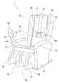
前記各図において本実施形態に係るマッサージ機1は、着座した被施療者を支える椅子状のものであり、詳細には、床面上に載置されて椅子全体を安定的に支持する基台部11と、この基台部11の上方で被施療者の臀部を支える座部12と、この座部12の後側で被施療者の背中を支える背もたれ部13と、座部12の左右両側で被施療者の肘や前腕部を支える肘掛部14と、座部12の前側で被施療者の脚を支える脚支持部15と、マッサージ動作に係る各種操作入力を受付けるリモコン30と、搭載されている複数の施療機構によるマッサージ動作を操作入力や記録情報等の内容に基づいて制御する制御部40とを備える構成である。
(First embodiment for reference of the present invention)
Hereinafter, a massage machine according to a first embodiment serving as a reference of the present invention will be described with reference to FIGS.
In each of the drawings, the massage machine 1 according to the present embodiment is a chair-like body that supports a seated user, and in detail, is a base that is placed on the floor and stably supports the entire chair. Part 11, a seat part 12 that supports the user's buttocks above the base part 11, a backrest part 13 that supports the user's back on the back side of the seat part 12, and both left and right sides of the seat part 12 The armrest 14 that supports the elbow and forearm of the user, the leg support 15 that supports the leg of the user on the front side of the seat 12, and the remote controller 30 that receives various operation inputs related to the massage operation. And a control unit 40 that controls the massage operation by the plurality of treatment mechanisms based on the contents of operation input, recorded information, and the like.

前記基台部11は、椅子各部をなす前記座部12、背もたれ部13、肘掛部14、及び脚支持部15を一体に取付けられてこれらを支持するものである。また、前記座部12は、基台部11に対し座面の傾斜角度を調整可能として取付けられ、座面にて被施療者の臀部や太腿部を支えつつ内蔵の施療機構でマッサージを実行するものであり、この施療機構として、空気の給排で動作する臀部用エアセル71、及び太腿部用エアセル72を備える構成である。これらエアセルを空気の給排で動作させるエアポンプ70が座部12下側のスペースに配設される。   The base 11 is configured to integrally support the seat 12, the backrest 13, the armrest 14, and the leg support 15 that constitute each part of the chair. The seat portion 12 is attached to the base portion 11 so that the inclination angle of the seat surface can be adjusted, and massage is performed by a built-in treatment mechanism while supporting the user's buttocks and thighs on the seat surface. As the treatment mechanism, the heel part air cell 71 and the thigh part air cell 72 that operate by supplying and discharging air are provided. An air pump 70 that operates these air cells by supplying and discharging air is disposed in a space below the seat portion 12.

臀部用エアセル71や太腿用エアセル72は、マッサージ機能以外にも、被施療者の体を昇降させたりクッションとしての機能を有する。   In addition to the massage function, the buttocks air cell 71 and the thigh air cell 72 have functions of raising and lowering the body of the user and as a cushion.

前記背もたれ部13は、人の背中形状に合せた表面形状とされて前記基台部11及び座部12に対し傾斜角度を調整可能として配設され、その内部に、マッサージを実行する施療機構を備える構成である。   The backrest portion 13 has a surface shape that matches the shape of the human back and is arranged so that the inclination angle can be adjusted with respect to the base portion 11 and the seat portion 12, and a treatment mechanism for performing massage is provided therein. It is the composition provided.

背もたれ部13内部には、施療子としての左右一対の揉み玉51とこれを動作させる駆動機構部60が一体となったメカユニット50と、このメカユニット50を背もたれ部13上下方向に移動可能とし且つ他方向への動きは拘束して支持する左右一対のガイドレール20と、前記エアポンプ70による空気の給排で動作する背中用エアセル73及び腰用エアセル74と、この背もたれ部13の形状を内部から維持する枠状のフレーム17とがそれぞれ配設される構成である。このうちメカユニット50、背中用エアセル73、及び腰用エアセル74が、それぞれマッサージを実行する施療機構をなす。   Inside the backrest 13, a mechanical unit 50 in which a pair of left and right kneading balls 51 as a treatment element and a drive mechanism 60 for operating the same are integrated, and the mechanical unit 50 can be moved in the vertical direction of the backrest 13. In addition, a pair of left and right guide rails 20 that restrains and supports movement in the other direction, a back air cell 73 and a waist air cell 74 that operate by supplying and discharging air by the air pump 70, and the shape of the backrest portion 13 are formed from the inside. A frame-like frame 17 to be maintained is arranged. Of these, the mechanical unit 50, the back air cell 73, and the waist air cell 74 each constitute a treatment mechanism for performing massage.

なお、この背もたれ部13の左右両側部には、被施療者に面する内面側にエアセル等の施療機構を設けた一対の側壁部を突出配設して、被施療者の上腕部等に対して側方からマッサージを行えるようにすることもできる。   In addition, a pair of side wall portions provided with a treatment mechanism such as an air cell on the inner surface facing the user is provided on both the left and right sides of the backrest portion 13 so as to protrude from the upper arm of the user. You can also make it possible to massage from the side.

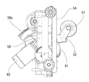
前記メカユニット50は、揉み、叩き等の刺激を被施療者に与える施療子としての左右一対の揉み玉51と、これら揉み玉51をそれぞれ突出状態で支持する左右一対の揉み玉支持アーム52と、この揉み玉支持アーム52を介して揉み玉51を揉み、叩き等のマッサージ動作に対応させて駆動する駆動機構部60と、背もたれ部上下方向に直交する軸線を中心として駆動機構部60を傾動可能に支持するベース部54とを備える構成である。   The mechanical unit 50 includes a pair of left and right rubbing balls 51 as a treatment element that gives a user a stimulus such as rubbing and hitting, and a pair of left and right rubbing ball support arms 52 that respectively support the rubbing balls 51 in a protruding state. The drive mechanism 60 that drives the massage balls 51 in response to massage operations such as hitting and the like, and the axis of the backrest that is perpendicular to the vertical direction is tilted about the drive mechanism 60. It is the structure provided with the base part 54 supported so that it is possible.

前記駆動機構部60は、ベース部54に対し傾動可能に支持されるハウジング61と、このハウジング61と一体に配設され、制御部40の制御に基づいて揉み玉51に揉み動作を行わせるための駆動力を発生させる揉みモータ62と、同じくハウジング61と一体に配設され、制御部40の制御に基づいて揉み玉51に叩き動作を行わせるための駆動力を発生させる叩きモータ64と、ハウジング61に内蔵されて、各モータからの運動を揉み玉支持アーム52を介して揉み玉51に伝達する揉み機構及び叩き機構(図示を省略)とを備える、公知のマッサージ機に用いられるものと同様の機構である。   The drive mechanism 60 is disposed integrally with the housing 61 that is supported so as to be tiltable with respect to the base 54, and causes the kneading balls 51 to perform a kneading operation based on the control of the control unit 40. A kneading motor 62 for generating a driving force of the same, and a tapping motor 64 that is disposed integrally with the housing 61 and that generates a driving force for causing the kneading balls 51 to perform a tapping operation based on the control of the control unit 40; Used in a known massage machine, which is built in the housing 61 and includes a kneading mechanism and a striking mechanism (not shown) that transmit motion from each motor to the kneading balls 51 via the kneading ball support arms 52. It is the same mechanism.

なお、揉み機構は、制御部40の制御に基づく揉みモータ62の回転で揉み玉支持アーム52が連続して揺れる状態を生じさせるものである。揉み玉支持アーム52の一端部に取付けられた揉み玉51は、揉み玉支持アーム52の動きに伴い、連続する軌跡を描きつつ上下、左右及び前後に揺動することで、施療動作としての揉みを実現できる。   The stagnation mechanism causes the stagnation ball support arm 52 to continuously sway due to the rotation of the stagnation motor 62 based on the control of the control unit 40. The kneading ball 51 attached to one end of the kneading ball support arm 52 swings up and down, left and right and back and forth while drawing a continuous trajectory along with the movement of the kneading ball support arm 52, and thereby itching as a treatment operation. Can be realized.

揉みの施療における揉み玉51の被施療者に対する揺動の変位は、揉みモータ62の回転作動の結果としての、揉み機構で揉み玉支持アーム52を駆動する駆動軸(図示を省略)の回転角度変位と一対一に対応していることから、駆動軸の変位を変位検出手段としてのエンコーダ65を用いて検出することで、制御部40で揉み玉51の揺動状態、すなわち揉み玉位置の変化を把握することができる。エンコーダ65は、駆動機構部60のハウジング61に内蔵され、ハウジング61側に固定されるセンサ部と、駆動軸側に取付けられるスケール部との組合せで構成され、センサ部で駆動軸と共に動くスケール部の回転角度変位を検出する、公知のロータリーエンコーダであり、制御部40に駆動軸の変位に係る信号を出力する。
また、叩き機構は、叩きモータ64の回転により、揉み玉支持アーム52を所定位置を中心に揺動させるものであり、揉み玉支持アーム52の揺動でアーム一端部の揉み玉51も前後に揺動(往復動)して、施療動作としての叩きを実現する仕組みである。
The displacement of the swirling ball 51 swinging relative to the user during the kneading treatment is the rotation angle of the drive shaft (not shown) that drives the kneading ball support arm 52 by the kneading mechanism 62 as a result of the rotation operation of the kneading motor 62. Since it corresponds to the displacement on a one-to-one basis, the displacement of the drive shaft is detected by using the encoder 65 as the displacement detection means, so that the control unit 40 swings the kneading balls 51, that is, changes in the kneading ball position. Can be grasped. The encoder 65 is built in the housing 61 of the drive mechanism 60, and is composed of a combination of a sensor unit fixed to the housing 61 side and a scale unit attached to the drive shaft side, and the scale unit moves with the drive shaft in the sensor unit. This is a known rotary encoder that detects the rotation angle displacement of the motor, and outputs a signal related to the displacement of the drive shaft to the control unit 40.
The hitting mechanism swings the kneading ball support arm 52 around a predetermined position by the rotation of the hitting motor 64, and the kneading ball 51 at one end of the arm also moves back and forth by the swinging of the kneading ball support arm 52. It is a mechanism that swings (reciprocates) and realizes a hit as a treatment operation.

前記ベース部54は、駆動機構部60を傾動可能に支持するものであり、この他、制御部40の制御に基づいて、メカユニット昇降用の駆動力を発生させる昇降モータ57と、駆動機構部60を傾動させる駆動力を発生させる進退モータ58とを備える構成である。   The base portion 54 supports the drive mechanism portion 60 so as to be tiltable. In addition, based on the control of the control portion 40, a lift motor 57 that generates a drive force for lifting the mechanical unit, and a drive mechanism portion. And an advancing / retracting motor 58 for generating a driving force for tilting 60.

進退モータ58は、制御部40の制御に基づいて、連動する小歯車58aを回転させ、この小歯車58aと噛合している駆動機構部60側の歯部67を移動させることで、駆動機構部60をベース部54に対し傾動させ、これにより揉み玉51位置を被施療者に対し進退させ、揉み玉51の被施療者側への突出量を調整するものである。   The advance / retreat motor 58 rotates the interlocking small gear 58a based on the control of the control unit 40, and moves the tooth portion 67 on the drive mechanism unit 60 side meshing with the small gear 58a, thereby driving the drive mechanism unit. 60 is tilted with respect to the base portion 54, whereby the kneading balls 51 are moved forward and backward with respect to the user, and the amount of the kneading balls 51 protruding toward the user is adjusted.

揉み玉51の被施療者に対する進退方向の変位は、進退モータ58の回転作動の結果としての駆動機構部60の傾動に係る角度変位と一対一に対応していることから、駆動機構部60の角度変位を変位検出手段としてのエンコーダ55を用いて検出することで、制御部40で駆動機構部60の傾動状態変化と共に、揉み玉51の進退状態、すなわち突出量の変化を把握することができる。エンコーダ55は、ベース部54に固定されるセンサ部55aと、駆動機構部60のハウジング61に取付けられるスケール部55bとの組合せで構成され、センサ部55aで駆動機構部60と共に動くスケール部55bの傾動変位を検出する、一種のロータリーエンコーダであり、制御部40に駆動機構部60の角度変位に係る信号を出力する。   The displacement of the kneading balls 51 in the advancing / retreating direction with respect to the user corresponds one-to-one with the angular displacement related to the tilting of the driving mechanism unit 60 as a result of the rotation operation of the advancing / retreating motor 58. By detecting the angular displacement using the encoder 55 as a displacement detecting means, the controller 40 can grasp the forward / backward state of the kneading balls 51, that is, the change in the protrusion amount, together with the tilting state change of the drive mechanism unit 60. . The encoder 55 is configured by a combination of a sensor unit 55a fixed to the base unit 54 and a scale unit 55b attached to the housing 61 of the drive mechanism unit 60. The encoder unit 55a includes a scale unit 55b that moves together with the drive mechanism unit 60 at the sensor unit 55a. This is a kind of rotary encoder that detects tilt displacement, and outputs a signal related to the angular displacement of the drive mechanism section 60 to the control section 40.

メカユニット50は、ベース部54の側端部を一対のガイドレール20にそれぞれ上下走行可能に支持されることで、ガイドレール20に挟まれる配置状態となり、メカユニット50全体としてガイドレール20に沿って移動可能とされる構成である。そして、制御部40による制御に基づき、昇降モータ57が作動してベース部54がガイドフレーム20を走行する状態となることで、ベース部54を含むメカユニット50全体が、ガイドフレーム20に沿って背もたれ部13の上下に移動することとなり、背もたれ部13における揉み玉51の位置(揉み玉による施療対象部位)を上下に変えられる仕組みである。   The mechanical unit 50 is placed between the guide rails 20 by supporting the side end portions of the base portion 54 so as to be able to run up and down by the pair of guide rails 20, and the mechanical unit 50 as a whole follows the guide rails 20. This configuration is movable. Then, based on the control by the control unit 40, the lifting motor 57 is actuated so that the base unit 54 travels along the guide frame 20, so that the entire mechanical unit 50 including the base unit 54 extends along the guide frame 20. This is a mechanism that moves up and down the backrest part 13 so that the position of the kneading balls 51 in the backrest part 13 (the treatment target site by the kneading balls) can be changed up and down.

そして、メカユニット50は、設定されたマッサージの内容に応じて、制御部40による制御で、上記のように背もたれ部13の上下に移動し、揉み玉51の上下位置を調整されると共に、進退モータ58の作動による揉み玉51と駆動機構部60の傾動で、揉み玉51の被施療者側への突出量を調整されて、揉み玉51をマッサージの対象箇所に位置させる。揉み玉51の移動後、又はこうした揉み玉51の移動と並行して、制御部40が、マッサージの種類に応じて、メカユニット50における駆動機構部60の揉み、叩き用のモータを作動させ、揉み玉51に設定された揉みや叩き等のマッサージに対応した動きを行わせることとなる。   The mechanical unit 50 moves up and down the backrest 13 as described above under the control of the control unit 40 in accordance with the set massage content, and adjusts the vertical position of the kneading balls 51 and advances and retreats. The amount of protrusion of the kneading balls 51 toward the user is adjusted by the tilting of the kneading balls 51 and the drive mechanism 60 by the operation of the motor 58, and the kneading balls 51 are positioned at the massage target location. After the movement of the kneading balls 51 or in parallel with the movement of the kneading balls 51, the control unit 40 activates the motor for kneading and hitting the drive mechanism 60 in the mechanical unit 50 according to the type of massage. The movement corresponding to massage such as itchiness and hitting set in the kneading balls 51 is performed.

前記肘掛部14は、座部12の両側に位置して基台部11と一体に連結し、背もたれ部13がリクライニング角度を変化させたり、座部12が傾動しても、被施療者の前腕を安定的に支持するよう形成される構成である。この肘掛部14にも、前記エアポンプ70による空気の給排で動作するエアセルを配設して、被施療者の前腕部に対しマッサージを行える構成としてかまわない。   The armrest part 14 is located on both sides of the seat part 12 and is integrally connected to the base part 11. Even if the backrest part 13 changes the reclining angle or the seat part 12 tilts, the forearm of the user It is the structure formed so that it may be supported stably. The armrest portion 14 may also be configured such that an air cell that operates by supplying and discharging air by the air pump 70 can be provided to massage the forearm portion of the user.

前記脚支持部15は、座部12の前側に位置し、座部12前端付近を中心として傾動可能に配設され、座部下側の第2アクチュエータ19により傾斜角度を調整されるものである。詳細には、脚支持部15は、座部12に対し傾動可能に取付けられる基礎部15aと、この基礎部15aの表面側部分に脚長手方向へ移動可能として配設され、脚に接する脚受部15bと、この脚受部15bに内蔵され、前記エアポンプ70による空気の給排で膨縮動作する施療機構としての脚用エアセル75、76、77、78とを備える構成である。   The leg support portion 15 is positioned on the front side of the seat portion 12 and is disposed so as to be tiltable around the vicinity of the front end of the seat portion 12. The tilt angle is adjusted by a second actuator 19 below the seat portion. Specifically, the leg support portion 15 is provided with a base portion 15a that is attached to the seat portion 12 so as to be tiltable, and is disposed on the surface side portion of the base portion 15a so as to be movable in the leg longitudinal direction. And a leg air cell 75, 76, 77, 78 as a treatment mechanism built in the leg receiving part 15 b and inflating and contracting by supplying and discharging air by the air pump 70.

前記第2アクチュエータ19は、固定部分に対し可動部分を直線移動させることで全体として所定範囲内で伸縮して長さを変化させる機構を有してなり、座部12の下側で一端部の位置を固定状態とされる一方、他端部が脚支持部15の裏面側に当接可能とされ、伸縮による他端部の位置変化に伴って、脚支持部を傾動させる構成である。つまり、本実施例においては、この第2アクチュエータが脚支持部15の傾動手段となる。   The second actuator 19 has a mechanism for moving the movable part linearly with respect to the fixed part so as to expand and contract within a predetermined range as a whole, and to change the length. While the position is fixed, the other end can be brought into contact with the back side of the leg support 15 and the leg support is tilted in accordance with a change in the position of the other end due to expansion and contraction. That is, in the present embodiment, this second actuator serves as a tilting means for the leg support portion 15.

この第2アクチュエータ19と一体に、第2アクチュエータ19の可動部分の変位、すなわち伸縮の変位を、所定の単位量の変位ごとの信号出力に基づき検出する、変位検出手段としてのリニアエンコーダが配設される。   A linear encoder as a displacement detecting means is provided integrally with the second actuator 19 for detecting the displacement of the movable portion of the second actuator 19, that is, the displacement of the expansion and contraction based on the signal output for each predetermined unit amount of displacement. Is done.

脚支持部15は、この第2アクチュエータ19の伸縮動作により、脚支持部15の裏面側に当接する第2アクチュエータ19他端部の位置が変ることで、座部12前端の軸部を中心として傾動し、傾斜角度を変化させる仕組みである。脚支持部15の傾動に係る変位は、第2アクチュエータ19の伸縮による変位と一対一に対応していることから、第2アクチュエータ19の伸縮変位を変位検出手段としてのリニアエンコーダを用いて検出することで、制御部40で第2アクチュエータ19の伸縮状態変化と共に、脚支持部15の傾動状態変化を把握することができる。なお、脚支持部15の傾動状態の把握にあたっては、直接脚支持部の傾斜角度変化をロータリーエンコーダ等の変位検出手段で取得するようにしてもよい。   The position of the other end of the second actuator 19 that contacts the back side of the leg support 15 is changed by the expansion / contraction operation of the second actuator 19, so that the leg support 15 is centered on the shaft at the front end of the seat 12. It is a mechanism that tilts and changes the tilt angle. Since the displacement associated with the tilting of the leg support portion 15 has a one-to-one correspondence with the displacement due to the expansion / contraction of the second actuator 19, the expansion / contraction displacement of the second actuator 19 is detected using a linear encoder as a displacement detection means. Thus, the control unit 40 can grasp the change in the tilting state of the leg support 15 together with the change in the expansion / contraction state of the second actuator 19. In grasping the tilting state of the leg support portion 15, the change in the tilt angle of the leg support portion may be directly acquired by a displacement detection means such as a rotary encoder.

このようなエンコーダーは、傾動位置を把握することで傾斜位置を検出する変位検出手段となるだけでなく、傾斜位置の変化により傾動の移動速度を検出することが可能なので傾動の移動速度を検出する速度検出手段となる。   Such an encoder not only serves as a displacement detecting means for detecting the tilt position by grasping the tilt position, but also detects the tilt moving speed by changing the tilt position, so that the tilt moving speed is detected. It becomes a speed detection means.

脚支持部15のうち脚受部15bは、被施療者の脚が入る凹状部分を生じさせた略半円筒状に形成され、座部12前端に取付けられた基礎部15aに対し脚長手方向へ移動可能に配設される構成である。脚受部15bの凹状部分を挟んで対向する側面部には、脚用エアセル75、76、77、78が、膨張状態で左右の脚のふくらはぎ部分をそれぞれ押圧してマッサージが行えるように、左右各々で対をなす配置として内蔵される。   The leg receiving part 15b of the leg support part 15 is formed in a substantially semi-cylindrical shape in which a concave part into which a user's leg enters is formed, and in the leg longitudinal direction with respect to the base part 15a attached to the front end of the seat part 12. It is the structure arrange | positioned so that a movement is possible. The leg air cells 75, 76, 77, 78 on the side surfaces facing each other across the concave portion of the leg receiving portion 15 b can be massaged by pressing the calf portions of the left and right legs in an expanded state. They are built in as a paired arrangement.

この脚支持部15には、脚用エアセル75、76、77、78の他、脚長手方向に移動しつつ脚を押圧するローラ等の他の施療機構を配設するようにしてもかまわない。   In addition to the leg air cells 75, 76, 77, 78, other treatment mechanisms such as rollers that press the legs while moving in the leg longitudinal direction may be disposed on the leg support portion 15.

被施療者は、左右の脚受部15bにそれぞれ左右の脚をふくらはぎ部分を中心として支持させることとなる。この支持状態で、左右でそれぞれ脚を挟んで対向する脚用エアセル75、76、77、78をいずれも膨張させると、脚のふくらはぎ部分を両側から押圧して挟持できる仕組みである。   The user supports the left and right legs around the calf portion by the left and right leg receiving portions 15b. In this supported state, when the leg air cells 75, 76, 77, 78 facing each other with the legs sandwiched between the left and right are inflated, the calf portions of the legs can be pressed and held from both sides.

すなわち、脚用エアセル75、76、77、78は、空気吸排に伴う膨張、収縮による直接的なマッサージ機能以外に、膨張状態の押圧力を利用して脚を挟持し、脚の想定外の動きを抑える挟持手段としての機能も有する。なお、この挟持する手段としては、エアセルの膨張収縮を利用するもの以外に、押圧片を機械的に移動させて脚を挟持する機構等でもよく、エアセルに限られるものではない。   That is, the leg air cells 75, 76, 77, and 78 hold the legs by using the pressing force in the expanded state in addition to the direct massage function due to the expansion and contraction due to the air intake / exhaust, and unexpected movement of the legs It also has a function as a clamping means for suppressing the above. In addition to the means for utilizing the expansion and contraction of the air cell, the means for clamping may be a mechanism that mechanically moves the pressing piece to clamp the leg, and is not limited to the air cell.

また、必ずしも脚の両側から脚用エアセル等の挟持手段を動作させて脚を挟持する構成に限らず、脚を挟んで対向する脚受部の左右の側壁のいずれか片側のみから脚を押圧し、脚受部の反対側の側壁に脚を押付けるようにして、挟持状態を得る構成としてもかまわない。   In addition, the leg is not necessarily configured to operate the leg air cell or the like from both sides of the leg to clamp the leg, and the leg is pressed only from one of the left and right side walls of the leg receiving portion facing each other across the leg. The sandwiching state may be obtained by pressing the leg against the side wall on the opposite side of the leg receiving portion.

このような構成において、脚用エアセル75、76、77、78が被施療者の脚を狭持して、脚を脚支持部15上に保持固定した状態で、第2アクチュエータ19を伸縮させ、脚支持部15を上下方向に傾動させると脚曲げ施療を行うことが出来る。なお、脚曲げ施療とは脚支持部を下方向に傾動させる動作による太腿の表側をストレッチさせる施療と上方向の傾動によって太腿の裏側をストレッチする施療のいずれをも含む。   In such a configuration, the leg air cells 75, 76, 77, 78 hold the user's leg and hold and fix the leg on the leg support 15, and the second actuator 19 is expanded and contracted, When the leg support 15 is tilted up and down, leg bending treatment can be performed. Note that the leg bending treatment includes both a treatment for stretching the front side of the thigh by an operation of tilting the leg support portion downward and a treatment for stretching the back side of the thigh by an upward tilt.

また、脚支持部15における脚受部15bを基礎部15aに対し座部12から遠ざかる方向に移動させると、脚伸ばし施療を行うことが出来る。   Moreover, when the leg receiving part 15b in the leg support part 15 is moved in the direction away from the seat part 12 with respect to the base part 15a, leg extension treatment can be performed.

脚支持部15の脚受部15bを基礎部15aに対し脚長手方向に移動させる機構としては、脚受部15bの基礎部15aに対する位置変化を検出するための変位検出手段15dと共に、所定の第1アクチュエータ18を用い、この第1アクチュエータ18の作動を制御部40で制御するようにしている。この第1アクチュエータ18は、モータや流体圧シリンダなどの公知のアクチュエータであり、また、変位検出手段15dは、公知のリニアエンコーダ等であり、詳細な説明を省略する。   As a mechanism for moving the leg receiving portion 15b of the leg supporting portion 15 in the longitudinal direction of the leg with respect to the base portion 15a, a predetermined first detection mechanism is used together with a displacement detecting means 15d for detecting a change in position of the leg receiving portion 15b with respect to the base portion 15a. One actuator 18 is used, and the operation of the first actuator 18 is controlled by the control unit 40. The first actuator 18 is a known actuator such as a motor or a fluid pressure cylinder, and the displacement detection means 15d is a known linear encoder or the like, and will not be described in detail.

また、上記脚曲げ施療と脚伸ばし施療を組み合わせた脚のストレッチ施療を実行することができる。   Moreover, the leg stretch treatment which combined the said leg bending treatment and the leg extension treatment can be performed.

脚のストレッチ施療において、脚曲げ施療と脚伸ばし施療を組み合わせる場合、上述の脚支持部を下方向に傾動させる動作による太腿の表側をストレッチさせる施療と上方向の傾動によって太腿の裏側をストレッチする施療のいずれの施療も組み合わせることが可能であるが、下記の実施形態では、脚支持部を上方向に傾動させつつ脚受部を座部12から遠ざかる方向に移動させる太腿の裏側のストレッチ施療につき説明する。   When combining leg bending treatment and leg stretching treatment in leg stretching treatment, the back side of the thigh is stretched by the treatment of stretching the front side of the thigh by tilting the above-mentioned leg support part downward and tilting upward. Any of the treatments to be performed can be combined, but in the following embodiment, the leg support is tilted upward and the leg support is moved in the direction away from the seat 12 to stretch the back side of the thigh I explain about treatment.

脚用エアセル75、76、77、78が被施療者の脚を狭持して、脚を脚支持部15上に保持固定した状態で、第2アクチュエータ19を伸長させ、脚支持部15を上向きに傾動させ、且つ脚支持部15における脚受部15bを基礎部15aに対し座部12から遠ざかる方向に移動させると、脚の裏側部分(脚裏部)に伸びによるストレッチ効果を付与できる。すなわち、脚支持部15を用いて脚裏部へのストレッチ施療を行える仕組みとなっている。なお、ここでの脚裏部とは、太腿部の裏、脹脛、及び膝裏の、一部又は全部を指すものである。   With the leg air cells 75, 76, 77, 78 holding the legs of the user and holding and fixing the legs on the leg support 15, the second actuator 19 is extended and the leg support 15 is directed upward When the leg receiving portion 15b in the leg support portion 15 is moved in the direction away from the seat portion 12 with respect to the base portion 15a, a stretch effect due to elongation can be imparted to the back side portion (leg back portion) of the leg. That is, the leg support 15 is used to perform stretch treatment on the leg back. In addition, the leg back part here refers to a part or all of the back of the thigh, the calf, and the back of the knee.

脚支持部15の傾動においては、脚を脚支持部15上に拘束するだけではなく、脚を挟持している脚受部15bの位置を座部から離れる向きに適宜移動させて、脚の曲り具合を調整することで、膝に無理な力が加わらないようにして膝の浮上がりを確実に抑え、脚のストレッチ効果をより高めることができる。   In tilting the leg support portion 15, not only the leg is restrained on the leg support portion 15 but also the position of the leg receiving portion 15 b holding the leg is moved appropriately in a direction away from the seat portion to bend the leg. By adjusting the condition, the knee lift can be reliably suppressed without applying excessive force to the knee, and the leg stretching effect can be further enhanced.

なお、脚受部15bの移動状態の把握にあたっては、直接脚受部15bの位置変化を変位検出手段15dで取得する他に、第1アクチュエータ18の可動部分の変位を、これと一体に設けられたリニアエンコーダ等の変位検出手段で取得するようにしてもよい。すなわち、脚受部15bは、第1アクチュエータ18の動作により、脚支持部15の基礎部15aに対して位置を変えることで、座部12に対して移動する仕組みであり、脚受部15bの移動に係る変位は、第1アクチュエータ18の作動による伸縮変位と一対一に対応することから、第1アクチュエータ18の変位を一体の変位検出手段を用いて検出することで、制御部40で第1アクチュエータ18の状態変化と共に、脚受部15bの移動状態変化を把握することができる。   In order to grasp the movement state of the leg receiving portion 15b, in addition to directly acquiring the position change of the leg receiving portion 15b by the displacement detecting means 15d, the displacement of the movable portion of the first actuator 18 is provided integrally therewith. Alternatively, it may be acquired by a displacement detection means such as a linear encoder. That is, the leg receiving portion 15b is a mechanism that moves with respect to the seat portion 12 by changing the position with respect to the base portion 15a of the leg supporting portion 15 by the operation of the first actuator 18, and the leg receiving portion 15b Since the displacement associated with the movement corresponds to the expansion / contraction displacement caused by the operation of the first actuator 18, the first displacement is detected by the control unit 40 by detecting the displacement of the first actuator 18 using an integral displacement detection means. Along with a change in the state of the actuator 18, a change in the movement state of the leg receiving portion 15b can be grasped.

さらに、脚支持部15の上向きの傾動に際し、脚の大腿部を挟持する別の挟持用エアセル79を、座部12の両側に配設する構成とすることもできる(図8参照)。この場合、座部12の両側の挟持用エアセル79で大腿部を挟持した状態で、脚支持部15が上向きに傾動して、脚を伸張させることで、エアセル79で挟持された太腿部が座部12の座面から浮き上がるのを抑えられ、脚支持部15の傾動による脚の伸張がより一層促されて、脚裏のストレッチ効果をより高めることができる。   Further, when the leg support portion 15 is tilted upward, another sandwiching air cell 79 for sandwiching the thigh of the leg may be disposed on both sides of the seat portion 12 (see FIG. 8). In this case, in the state where the thighs are clamped by the clamping air cells 79 on both sides of the seat part 12, the leg support 15 is tilted upward to extend the legs, whereby the thighs clamped by the air cells 79 Can be prevented from floating from the seating surface of the seat portion 12, and the leg can be stretched further by the tilting of the leg support portion 15, so that the stretch effect of the back of the leg can be further enhanced.

一方、脚用エアセルによる脚の挟持状態で、脚支持部15を上方から下方に傾動させることもでき、この場合には、脚の他部分に対して伸びによるストレッチ効果を与えられる。   On the other hand, the leg support portion 15 can be tilted downward from above while the leg is held by the leg air cell, and in this case, the stretch effect by stretching is given to the other part of the leg.

前記リモコン30は、マッサージ機に対する各種操作入力を受付ける多数のスイッチや表示部を備え、マッサージ機1の側部におけるスタンド16に着脱自在に設置され、マッサージに係る操作入力を制御部40に送信するものである。なお、リモコン30のスイッチや表示部の位置を被施療者にとって最適位置とするために、スタンド16の位置は調整可能となっている。   The remote controller 30 includes a large number of switches and display units for receiving various operation inputs to the massage machine, is detachably installed on the stand 16 on the side of the massage machine 1, and transmits operation inputs related to massage to the control unit 40. Is. Note that the position of the stand 16 can be adjusted so that the position of the switch and the display unit of the remote controller 30 is the optimum position for the user.

前記制御部40は、あらかじめ被施療者の身体各部位置検出を実行して得られた検出結果に基づいて、施療機構やマッサージ機の他の各可動部分を被施療者に対応した状態に調整すると共に、施療機構や他の各可動部分に対し、リモコン操作やあらかじめ記録設定された施療内容、また前記検出結果の情報に基づいて、適切な施療の実行のための制御を行うものである。   The control unit 40 adjusts the other movable parts of the treatment mechanism and the massage machine to a state corresponding to the user based on the detection result obtained by detecting the positions of the body parts of the user in advance. At the same time, control for performing appropriate treatment is performed on the treatment mechanism and other movable parts based on the remote control operation, the treatment contents recorded and set in advance, and the information on the detection result.

この制御部40は、そのハードウェア構成として、CPUやメモリ、入出力インターフェース等を備えるコンピュータとなっており、メモリ等に格納されるプログラムにより、コンピュータを制御部40として動作させる仕組みである。この制御部40をなすコンピュータは、CPUやメモリ、ROM等を一体的に形成されたマイクロコンピュータとしてもかまわない。   The control unit 40 is a computer including a CPU, a memory, an input / output interface, and the like as its hardware configuration, and is a mechanism that causes the computer to operate as the control unit 40 by a program stored in the memory or the like. The computer constituting the control unit 40 may be a microcomputer in which a CPU, a memory, a ROM, and the like are integrally formed.

この制御部40をなすコンピュータのユニットは、座部12直下等のマッサージ機1内部の所定のスペースに配設され、リモコン30と通信可能な状態とされると共に、メカユニット50の各種モータや、背もたれ部13や脚支持部15を傾動させるアクチュエータ、エアポンプ70や給排気制御機構とそれぞれ電気的に接続され、被施療者の身体各部位置検出の際にはあらかじめ設定された位置検出用プログラムに基づく制御信号出力により、また、マッサージ実行の際には設定されたマッサージのデータに基づく制御信号出力により、これらの駆動機構の作動を制御する。   The computer unit constituting the control unit 40 is disposed in a predetermined space inside the massage machine 1 such as directly under the seat 12 and is in a state where it can communicate with the remote controller 30, and various motors of the mechanical unit 50, The actuator for tilting the backrest 13 and the leg support 15, the air pump 70, and the air supply / exhaust control mechanism are electrically connected to each other, and the position of each part of the body of the user is detected based on a preset position detection program. The operation of these drive mechanisms is controlled by the control signal output and by the control signal output based on the set massage data at the time of massage execution.

加えて、制御部40は、メカユニット50や各アクチュエータの変位量を出力するエンコーダ等の信号出力手段とも電気的に接続されており、メカユニット50の状態や、背もたれ部13及び脚支持部15の傾斜等の状態を把握しつつ、モータやアクチュエータ等の駆動手段の作動制御を行うこととなる。   In addition, the control unit 40 is also electrically connected to signal output means such as an encoder that outputs the displacement amount of the mechanical unit 50 and each actuator, and the state of the mechanical unit 50, the backrest portion 13 and the leg support portion 15 are also connected. The operation control of the driving means such as the motor and the actuator is performed while grasping the state such as the inclination of the motor.

特に、脚支持部15を傾動させる第2アクチュエータ19の作動状態を制御するにあたり、制御部40は、脚裏部へのストレッチ施療としての脚支持部15の傾動と同期した脚受部15bの移動における、ストレッチの施療強度に応じて第1アクチュエータ18に加わる負荷の変化と、この第1アクチュエータ18の作動に係る所定の物理量の変化との対応関係をあらかじめ把握して、制御の目安とする施療強度に対応する前記物理量の目安値を設定し、第1アクチュエータ18の作動の間、前記物理量を取得して、物理量が前記目安値に達した際に、第2アクチュエータ19に作動停止や作動速度低下等の、これまでの作動状態からの変化を起させる制御指令の送出を実行するようにしている。   In particular, in controlling the operation state of the second actuator 19 that tilts the leg support 15, the controller 40 moves the leg support 15 b in synchronization with the tilt of the leg support 15 as a stretch treatment to the leg back. , The correspondence between the change in the load applied to the first actuator 18 in accordance with the stretch treatment intensity and the change in the predetermined physical quantity related to the operation of the first actuator 18 is grasped in advance, and the treatment is used as a guide for control. A reference value of the physical quantity corresponding to the strength is set, the physical quantity is acquired during the operation of the first actuator 18, and when the physical quantity reaches the reference value, the second actuator 19 is deactivated or operated. A control command that causes a change from the previous operating state such as a decrease is sent out.

ストレッチ施療において、脚受部15bの移動に基づく施療強度の増大変化と脚受部15bの移動速度の減少変化とが、強い関係性を示すことがわかっており、この脚受部15bの移動の状況を各施療機構の作動制御に利用すれば、所定時点の実際の施療強度を的確に把握して、施療強度に応じた作動制御が見込めることとなる。このため、脚受部15bの移動を生じさせる機構として第1アクチュエータ18を用い、この第1アクチュエータ18の作動に係る物理量を制御の目安としている。   In the stretch treatment, it is known that an increase change in treatment intensity based on the movement of the leg support portion 15b and a decrease change in the movement speed of the leg support portion 15b show a strong relationship. If the situation is used for the operation control of each treatment mechanism, the actual treatment intensity at a predetermined time point can be accurately grasped, and the operation control according to the treatment intensity can be expected. For this reason, the first actuator 18 is used as a mechanism for causing the movement of the leg receiving portion 15b, and a physical quantity related to the operation of the first actuator 18 is used as a guide for control.

上記の第1アクチュエータ18の作動に係る所定の物理量としては、変位検出手段15dより得られる、脚受部15bの変位とこの変位の検出間隔とからの速度算出により取得した、脚受部15bの移動速度を用いている。   The predetermined physical quantity related to the operation of the first actuator 18 is that of the leg receiving portion 15b obtained by calculating the speed from the displacement of the leg receiving portion 15b and the detection interval of the displacement obtained from the displacement detecting means 15d. The moving speed is used.

そして、制御部40は、脚裏部へのストレッチ施療における施療強度を、マッサージ機の使用者、具体的には被施療者、に選択可能としてあらかじめ複数段階、例えば、強中弱の三段階設定しており、こうした複数段階の強度の中から使用者に選択されたものを目安とする施療強度として、この目安の強度に対応する前記物理量の目安値、本実施形態では脚受部15bの移動速度の目安値、を設定することとなる。   And the control part 40 can select the treatment intensity | strength in the stretch treatment to a leg back part to the user of a massage machine, specifically a to-be-treated person, in multiple steps, for example, three steps of strong, medium, and weak Therefore, the treatment intensity based on the strength selected by the user from the multiple levels of strength is used as a guide value of the physical quantity corresponding to the guide strength, and in this embodiment, the movement of the leg support 15b. A reference value for speed will be set.

こうして、第1アクチュエータ18の作動による脚受部15bの移動変位を示す変位検出手段15dの信号出力について、制御部40で、脚受部15bの座部12に対する位置関係の把握に用いる他、脚受部15bの変位とこの変位の検出間隔を用いて脚受部15bの移動速度を求めることで、ストレッチ施療において、実際に施療強度が高い場合など、第1アクチュエータ18の負荷が高くなり脚受部15bの移動速度、すなわち、第1アクチュエータ18の作動速度が低下した状態を検知できることとなる。こうした速度に基づいて、例えば第2アクチュエータ19の制御を行うようにすれば、設定した施療強度が実際に得られる状態を目安として第2アクチュエータ19を作動させられ、傾動角度など変位そのものに基づいて制御を行う場合のように、個人ごとの脚の長さの差に伴う限界傾動角度の違いによる施療強度のばらつき等を生じさせない。   Thus, the signal output of the displacement detecting means 15d indicating the displacement of the leg receiving portion 15b due to the operation of the first actuator 18 is used by the control portion 40 for grasping the positional relationship of the leg receiving portion 15b with respect to the seat portion 12, By obtaining the moving speed of the leg receiving portion 15b by using the displacement of the receiving portion 15b and the detection interval of this displacement, the load on the first actuator 18 becomes higher in the stretch treatment when the treatment strength is actually high. It is possible to detect a state in which the moving speed of the portion 15b, that is, the operating speed of the first actuator 18 is reduced. For example, if the second actuator 19 is controlled on the basis of such a speed, the second actuator 19 can be operated with reference to a state where the set treatment intensity is actually obtained, and based on the displacement itself such as the tilt angle. As in the case of control, there is no variation in the treatment intensity due to the difference in the limit tilt angle that accompanies the difference in leg length for each individual.

この他、制御部40は、公知のマッサージ機と同様に、マッサージに先立つ被施療者の身体各部位置検出として、メカユニット50を制御し、メカユニット50を背もたれ部13における初期位置からガイドレール20に沿って移動させ、揉み玉51を被施療者に沿って動かす過程で、背もたれ部13にもたれた被施療者側からの揉み玉51に対する圧力の変化や揉み玉51の傾き変化等を順次取得し、この情報に基づいて、被施療者の肩位置、背骨のライン、腰位置を検出することもできる。   In addition to this, the control unit 40 controls the mechanical unit 50 to detect the position of each part of the body of the user prior to the massage, as in a known massage machine, and the mechanical unit 50 is moved from the initial position of the backrest 13 to the guide rail 20. In the process of moving the kneading balls 51 along the user, a change in pressure with respect to the kneading balls 51 from the user leaning against the backrest 13 and a change in the inclination of the kneading balls 51 are sequentially acquired. Based on this information, the shoulder position, spine line, and waist position of the user can also be detected.

次に、本実施形態に係るマッサージ機における被施療者の脚裏部ストレッチ施療過程について説明する(図7参照)。前提として、マッサージ機1に被施療者が着座して背中を背もたれ部13にもたれさせた状態で、マッサージ機1の主電源が入とされ、マッサージ機1が起動して、被施療者の体重や体形検出などのマッサージ開始前の準備動作や、背もたれ部13のリクライニング角度調整等が完了し、さらに、被施療者によりマッサージコース等の動作状態指示が入力されて、種々のマッサージ動作を実行する中で、制御部40が脚に対するストレッチ施療を実行しようとしているものとする。   Next, the leg back stretch treatment process of the user in the massage machine according to the present embodiment will be described (see FIG. 7). As a premise, the massage machine 1 is turned on when the user is seated on the massage machine 1 and the back is leaned against the backrest 13, the massage machine 1 is activated, and the weight of the user Preparation operations before starting massage such as body shape detection, reclining angle adjustment of the backrest 13 and the like are completed, and an operation state instruction such as a massage course is input by the user, and various massage operations are executed. In particular, it is assumed that the control unit 40 is about to perform a stretch treatment on the leg.

そして、制御部40は、ストレッチ施療に係る各部の作動制御開始前に、脚支持部15がその初期位置としての最も下部に下がった状態にない場合は、第2アクチュエータ19を縮方向に作動させ、脚支持部15を初期位置まで傾動させる。合わせて、脚支持部の脚受部15bが最も座部寄りの位置となっていない場合には、第1アクチュエータ18を動作させて脚受部15bを座部12に近づく向きに移動させておく。   Then, the control unit 40 operates the second actuator 19 in the contracting direction when the leg support unit 15 is not in the lowest position as its initial position before starting the operation control of each unit related to the stretch treatment. The leg support 15 is tilted to the initial position. At the same time, when the leg support 15b of the leg support is not closest to the seat, the first actuator 18 is operated to move the leg support 15b closer to the seat 12. .

制御部40は、ストレッチ施療における初期位置にある脚支持部15の、各機構部分の作動を開始させるにあたり、まず、あらかじめ設定されたストレッチの複数段階の施療強度、例えば、強、中、弱の三段階の施療強度のうち、被施療者が施療前に入力指示したか、マッサージコースの一部として選択設定されている施療強度を読出し、この施療強度にあらかじめ対応付けられて記録されている脚受部15bの移動速度の値を、制御の目安値として登録する(ステップS001)。   When starting the operation of each mechanism portion of the leg support 15 at the initial position in the stretch treatment, the control unit 40 first sets a plurality of treatment strengths of the preset stretch, for example, strong, medium, weak Of the three treatment intensities, the treatment instructed by the user prior to treatment or the treatment intensity selected and set as part of the massage course is read, and the leg that is recorded in association with this treatment intensity in advance. The value of the moving speed of the receiving unit 15b is registered as a control guide value (step S001).

この後、制御部40は、脚支持部15で脚の両側に位置する各脚用エアセルへの給気を実行してエアセルを膨張させる(ステップS002)(図5(B)、図8参照)。この脚用エアセルの膨張に伴い、脚のふくらはぎ部分がエアセルで両側から挟持され、脚受部15bに拘束されることとなる。   Thereafter, the control unit 40 causes the leg support unit 15 to supply air to each leg air cell located on both sides of the leg to inflate the air cell (step S002) (see FIGS. 5B and 8). . As the leg air cell expands, the calf portion of the leg is clamped from both sides by the air cell and is restrained by the leg receiving portion 15b.

脚用エアセルが十分に膨張して、ふくらはぎ部分が挟持、拘束された状態で、制御部40は最下部の初期位置にある脚支持部15に対し、第2アクチュエータ19を伸長させ、第2アクチュエータ19一端部で脚支持部15の裏面側を押して脚支持部15を上向きに傾動させる(ステップS003)。   In a state where the leg air cell is sufficiently expanded and the calf portion is sandwiched and restrained, the control unit 40 extends the second actuator 19 with respect to the leg support unit 15 at the lowermost initial position, and the second actuator 19 19 At one end, the back side of the leg support 15 is pushed to tilt the leg support 15 upward (step S003).

なお、座部12の両側に脚の大腿部を挟持する別のエアセルを配設している場合、制御部40は、この第2アクチュエータ19による脚支持部15の傾動開始前後、あるいは傾動開始と同時に、大腿部の挟持用エアセル79への給気を行い、これを膨張させ、大腿部の挟持を実行する(図8参照)。   In addition, when another air cell is provided on both sides of the seat portion 12 to hold the leg thigh, the control unit 40 starts before or after the leg actuator 15 tilts by the second actuator 19 or starts tilting. At the same time, air is supplied to the air cell 79 for holding the thigh, and the air cell 79 is inflated to hold the thigh (see FIG. 8).

第2アクチュエータ19による脚支持部15の傾動を開始させ、脚支持部15の端部が床からある程度離れた後、制御部40は脚支持部15の第1アクチュエータ18を作動させ、脚支持部15の脚受部15bを基礎部15aに対し座部12から離れる側となる脚先端側へ少しずつ移動させていく(ステップS004)(図6(A)参照)。   After the tilting of the leg support 15 by the second actuator 19 is started and the end of the leg support 15 is separated from the floor to some extent, the control unit 40 operates the first actuator 18 of the leg support 15 to move the leg support 15. The 15 leg receiving portions 15b are moved little by little toward the leg tip side which is the side away from the seat portion 12 with respect to the base portion 15a (step S004) (see FIG. 6A).

こうして、仮に脚受部15bが基礎部15aに対し動かない場合、脚支持部15の傾動に伴って脚支持部15前面部分と座部12上面との距離が縮まり、座部12及び脚支持部15上の脚の長さと対応しない状態となって、脚支持部15に拘束された関係で長手方向に動けない脚で、その膝部分が、余長を調整するように座部12先端部及び脚支持部15上端部から離れて脚裏の伸張が阻害される状態となったり、膝に負担(無理な力)が加わる状態となる問題点を、脚受部15bを脚先端側へ移動させることで解消でき、脚を座部12や脚支持部15に付けて脚裏の伸張が適切に生じる状態のままで、脚支持部15の上向きの傾動を継続できる状態が得られる(図6参照)。   Thus, if the leg receiving portion 15b does not move relative to the base portion 15a, the distance between the front surface portion of the leg support portion 15 and the upper surface of the seat portion 12 decreases as the leg support portion 15 tilts, and the seat portion 12 and the leg support portion 15 is a leg that does not correspond to the leg length on the leg 15 and cannot move in the longitudinal direction due to the restraint by the leg support 15, and the knee part of the leg 12 adjusts the extra length and The leg receiving part 15b is moved to the leg tip side in a state where the extension of the back of the leg is hindered away from the upper end part of the leg support part 15 or a load (unreasonable force) is applied to the knee. In this state, the leg support 15 can be continuously tilted upward with the legs attached to the seat 12 or the leg support 15 and the back of the leg is properly stretched (see FIG. 6). ).

この脚受部15bの脚先端側への移動は、脚支持部15の傾動状態に対応して、被施療者の足や脚支持部15の端部が床面に当接しない程度に移動量を調整しつつ実行される。   The movement of the leg receiving portion 15b toward the distal end side of the leg corresponds to the tilted state of the leg supporting portion 15 and the moving amount is such that the foot of the user and the end of the leg supporting portion 15 do not contact the floor surface. It is executed while adjusting.

一方、制御部40は、脚受部15bの移動開始と共に、変位検出手段15dの出力を受取り、脚受部15bの移動変位を把握すると共に、変位検出手段15dから得られる、脚受部15bの変位とこの変位の検出間隔とから、脚受部15bの移動速度を継続的に算出し、第2アクチュエータ19の作動制御の目安の情報として取得する(ステップS005)。   On the other hand, the control unit 40 receives the output of the displacement detection unit 15d as the movement of the leg receiving unit 15b starts, grasps the movement displacement of the leg receiving unit 15b, and obtains the displacement of the leg receiving unit 15b from the displacement detection unit 15d. From the displacement and the detection interval of the displacement, the moving speed of the leg receiving portion 15b is continuously calculated, and is acquired as information on the standard of operation control of the second actuator 19 (step S005).

制御部40の制御に基づき、第2アクチュエータ19を伸長させて、脚支持部15を上向きに傾動させ、被施療者の脚における膝より下の部分を持上げていく状態では、脚用エアセルで脚のふくらはぎ部分を拘束すると共に、脚受部15bを脚先端側に移動させて脚が座部と脚支持部上に接した状態を維持していることで、脚が適切な姿勢をとりつつ前方へ引張られる形となって、脚にストレッチ運動のような負荷が加わる状態となり、脚裏、特に大腿部裏側から膝裏にかけての部位が伸される状態となる。   Under the control of the control unit 40, the second actuator 19 is extended, the leg support unit 15 is tilted upward, and the leg below the knee is lifted by the leg air cell. The calf part is restrained and the leg receiving part 15b is moved to the tip side of the leg so that the leg is kept in contact with the seat part and the leg support part, so that the leg can move forward while taking an appropriate posture. As a result, the leg is subjected to a load such as stretching exercise, and the leg sole, in particular, the region extending from the back of the thigh to the back of the knee is stretched.

この脚支持部15の傾動の際には、必要に応じて背もたれ部13を起こす動作を連動させることもでき、背もたれ部13が起きて被施療者が上体を起こした姿勢を強いられることで、脚裏が伸びる向きの負荷がさらに加わる状態となり、脚裏へのストレッチ効果がさらに向上する。   When the leg support portion 15 is tilted, the operation of raising the backrest portion 13 can be interlocked as necessary, and the backrest portion 13 is raised to force the user to raise his / her upper body. Further, a load in the direction in which the soles extend is further applied, and the stretch effect to the soles is further improved.

この後、脚支持部15の傾動の進行で、脚支持部15の前面側が座部12の高さに達し、脚支持部15の傾動角度が被施療者の脚の可動範囲の限界に近づく(図6(B)参照)と共に、被施療者の脚の膝から下部分が座部12に対し移動しにくくなり、脚受部15bの座部12から離れる向きの移動において抵抗が加わる状態となる。これに伴い、脚受部15bを移動させる第1アクチュエータ18の負荷が急増し、脚受部15bの移動速度及びこれに係る第1アクチュエータ18の作動速度も大幅に低下する。   Thereafter, as the tilting of the leg support 15 proceeds, the front side of the leg support 15 reaches the height of the seat 12, and the tilt angle of the leg support 15 approaches the limit of the movable range of the legs of the user ( 6B), the lower part from the knee of the user's leg becomes difficult to move with respect to the seat part 12, and resistance is applied in the movement of the leg receiving part 15b away from the seat part 12. . Along with this, the load on the first actuator 18 that moves the leg receiving portion 15b increases rapidly, and the moving speed of the leg receiving portion 15b and the operating speed of the first actuator 18 related to the moving speed significantly decrease.

制御部40は、脚受部15bの移動開始から、脚受部15bの移動速度を継続的に取得しており、この低下状態にある速度が、先に設定された目安値に達したか否かを判定する(ステップS006)。   The control unit 40 continuously acquires the moving speed of the leg receiving unit 15b from the start of the movement of the leg receiving unit 15b, and whether or not the speed in this reduced state has reached the previously set reference value. Is determined (step S006).

ストレッチの施療強度が強くなるほど、第1アクチュエータ18の負荷も大となるなど、ストレッチ施療における施療強度と第1アクチュエータ18の負荷とは対応しており、また、第1アクチュエータ18の負荷上昇と脚受部15bの移動速度の低下度合も一定の関係性を有することがわかっていることから、制御部40では、あらかじめ設定されたストレッチの施療強度に対応する脚受部15bの移動速度を制御の目安値とし、第1アクチュエータ18を作動させる間、取得した脚受部15bの移動速度をこの目安値と比較照合する。   The higher the stretch treatment strength is, the greater the load on the first actuator 18 is. For example, the treatment strength in the stretch treatment and the load on the first actuator 18 correspond to each other. Since it is known that the degree of decrease in the moving speed of the receiving unit 15b has a certain relationship, the control unit 40 controls the moving speed of the leg receiving unit 15b corresponding to the predetermined stretch treatment intensity. As a reference value, the obtained movement speed of the leg receiving portion 15b is compared with the reference value while the first actuator 18 is operated.

制御部40は、取得した脚受部15bの移動速度が目安値に達したと判定すると、第2アクチュエータ19と脚用エアセルの給排制御機構に対し作動停止の制御指令を送出する。この後、第2アクチュエータ19は停止状態となり、脚支持部15の傾動が停止する(ステップS007)。これにより、あらかじめ選択、設定されたストレッチの施療強度を超えることなく脚支持部15の傾動が停止され、過剰なストレッチ施療が行われることはない。一方、前記ステップS006で速度が目安値に達していない場合には、前記ステップS003に戻って第2アクチュエータ19による脚支持部15の傾動を続行し、以降の過程を繰返す。
こうして脚受部15bの移動速度から施療強度を判断し、脚支持部15の傾動に係る第2アクチュエータ19の作動を制御しているので、脚の長さの個人差による傾動角度とストレッチの強度との関係の変化に影響を受けることなく、適切な施療強度でのストレッチが可能となる。
When the control unit 40 determines that the acquired movement speed of the leg receiving unit 15b has reached the reference value, the control unit 40 sends an operation stop control command to the second actuator 19 and the supply / discharge control mechanism of the leg air cell. Thereafter, the second actuator 19 is stopped, and the tilting of the leg support portion 15 is stopped (step S007). Thereby, tilting of the leg support part 15 is stopped without exceeding the stretch treatment strength selected and set in advance, and excessive stretch treatment is not performed. On the other hand, if the speed does not reach the reference value in step S006, the process returns to step S003 to continue the tilting of the leg support 15 by the second actuator 19, and the subsequent steps are repeated.
In this way, the treatment intensity is judged from the moving speed of the leg support 15b, and the operation of the second actuator 19 related to the tilt of the leg support 15 is controlled. Therefore, the tilt angle and the strength of the stretch due to individual differences in leg length. It is possible to stretch at an appropriate treatment strength without being affected by changes in the relationship with.

制御部40は、第2アクチュエータ19を停止させると共に、脚用エアセルを空気の排出により収縮させて脚を挟持状態から解放し(ステップS008)、また、別のエアセル79で大腿部を挟持している場合は、これについても空気排出により挟持状態から解放すると、脚が自由に動かせる状態に戻る。
この後、脚受部15bは、基礎部15aとの関係で座部12から離れる向きの移動限界に達し、これに応じて制御部40は第1アクチュエータ18を作動停止状態として(ステップS009)、一連のストレッチ施療が終了となる。(図9も参照) この実施形態では脚受部15bは、基礎部15aとの関係で座部12から離れる向きの移動限界に達するまで移動させているが、この脚受部15bも上記作動停止の制御指令に応じて停止位置を決定させてもよい。(図11参照)
The control unit 40 stops the second actuator 19 and contracts the leg air cell by discharging the air to release the leg from the nipping state (step S008), and nipping the thigh with another air cell 79. If this is the case, the leg will return to a state where it can be moved freely when it is released from the pinched state by air discharge.
Thereafter, the leg receiving part 15b reaches the movement limit in the direction away from the seat part 12 in relation to the base part 15a, and in response to this, the control part 40 puts the first actuator 18 into an operation stopped state (step S009). A series of stretch treatment ends. (See also FIG. 9) In this embodiment, the leg receiving portion 15b is moved until reaching the movement limit in the direction away from the seat portion 12 in relation to the base portion 15a. The stop position may be determined according to the control command. (See Figure 11)

また、この実施形態(図9)では脚支持部の傾動が停止し脚用エアセルの空気の排出が開始した後も、脚受部は引き続き移動を続けるのでストレッチ施療後に脚に対し弱い挟持状態でのさすり施療を行えている。   Further, in this embodiment (FIG. 9), even after the tilting of the leg support portion is stopped and the discharge of the air from the leg air cell is started, the leg receiving portion continues to move, so that the leg is weakly held against the leg after the stretch treatment. We are able to carry out the treatment.

もちろん、上記脚用エアセルの空気は、移動速度が目安値に達したことで排出を開始させる必要はなく、脚の挟持状態を維持させておいても良い。その場合、脚受部の移動速度は目安値に達した後も引き続き低下をつづける。そして場合によっては脚に強い引張力を与えるおそれがあるので、移動限界前に停止するように停止位置を決定することが望ましい。(図10参照)   Of course, the air in the leg air cell does not need to start discharging when the moving speed reaches the reference value, and the leg may be held in a clamped state. In that case, the movement speed of the leg support portion continues to decrease after reaching the reference value. In some cases, a strong tensile force may be applied to the leg. Therefore, it is desirable to determine the stop position so as to stop before the movement limit. (See Figure 10)

これ以降は、他のマッサージ等に移行し、制御部40は、脚支持部15の位置が次の施療に適さない場合、第2アクチュエータ19を縮方向に作動させて、脚支持部15を下向きに傾動させると共に、第1アクチュエータ18を動作させて脚受部15bを座部12に近づく向きに移動させるなど、脚支持部15を施療に適した位置となるよう調整することとなる。   Thereafter, the control unit 40 moves to another massage and the control unit 40 operates the second actuator 19 in the contracting direction to move the leg support unit 15 downward when the position of the leg support unit 15 is not suitable for the next treatment. The leg support 15 is adjusted to a position suitable for treatment, for example, the first actuator 18 is moved and the leg support 15b is moved closer to the seat 12.

なお、ストレッチの施療に係る各機構部分の作動のタイミングについては、上記のように、エアセルの膨張開始後、第2アクチュエータ19による脚支持部15の傾動を開始し、その後に第1アクチュエータ18を用いた脚受部15bの移動を開始するようにしている(図9ないし図11参照)が、これに限られるものではなく、脚支持部15の傾動開始位置で脚受部15bが移動しても、脚受部15や被施療者の足が床に付くおそれがない場合には、脚支持部15の傾動と脚受部15bの移動を同時に開始するようにすることもできる。   In addition, as for the operation timing of each mechanism part related to the stretch treatment, as described above, after the air cell starts to expand, the leg actuator 15 starts to tilt by the second actuator 19 and then the first actuator 18 is moved. The movement of the used leg receiving portion 15b is started (see FIGS. 9 to 11), but is not limited to this, and the leg receiving portion 15b is moved at the tilt start position of the leg supporting portion 15. In addition, when there is no possibility that the leg receiving part 15 or the foot of the user is attached to the floor, the tilting of the leg supporting part 15 and the movement of the leg receiving part 15b can be started at the same time.

また、大腿部を挟持する別のエアセル79を用いる際の、その膨張開始のタイミングは、図12ないし図14の各タイミング例に示すように、制御部40が脚支持部15の傾動開始後に脚受部15bの移動を開始させる場合と、脚支持部15の傾動と脚受部15bの移動を同時に開始する場合のいずれでも、第2アクチュエータ19による脚支持部15の傾動開始と同時、あるいは傾動開始の前又は後、のいずれの時点でもかまわない。   In addition, when another air cell 79 that holds the thigh is used, the timing of the expansion start is as shown in the timing examples of FIGS. 12 to 14 after the control unit 40 starts to tilt the leg support 15. Either when the movement of the leg support 15b is started and when the tilt of the leg support 15 and the movement of the leg support 15b are started simultaneously, or simultaneously with the start of the tilt of the leg support 15 by the second actuator 19. It does not matter at any time before or after the start of tilting.

このように、本実施形態に係るマッサージ機は、座部12の前側で傾動可能に脚を支持する脚支持部15を、座部12に取付けられる基礎部15aとこれに対し移動可能な脚受部15bとの組合せ構造とし、脚へのストレッチの施療として脚支持部15を上向きに傾動させる際に、あらかじめ脚部エアセルで脚を挟持して脚受部15b上に保持固定した状態とし、さらに傾動の進行に合わせて、脚受部15bを座部12から離れる向きに少しずつ移動させることから、脚を脚支持部15や座部12から浮かせることなく脚支持部15を上向きに傾動させて脚を伸して、膝に負担をかけることなく、効率よく脚裏部分の筋肉のストレッチを行う状態が得られることとなり、脚のストレッチに係る施療をスムーズ且つ適切に実行でき、被施療者に対し優れた施療効果を付与できる。   As described above, the massage machine according to the present embodiment includes the leg support portion 15 that supports the leg so as to be tiltable on the front side of the seat portion 12, the base portion 15 a attached to the seat portion 12, and a leg holder that is movable relative thereto. When the leg support 15 is tilted upward as a stretch treatment for the leg, the leg is sandwiched in advance by the leg air cell and is held and fixed on the leg receiver 15b. As the tilting progresses, the leg support 15b is moved little by little in a direction away from the seat 12, so that the leg support 15 is tilted upward without lifting the leg from the leg support 15 or the seat 12. The leg can be stretched efficiently without stretching the leg and straining the knee, and the treatment for stretching the leg can be performed smoothly and appropriately. Was excellent treatment effect can be imparted.

また、ストレッチ施療における施療強度と脚受部15bを移動させる第1アクチュエータ18の負荷とが対応し、且つ、脚受部15bの移動速度が第1アクチュエータ18の負荷の変化に応じて変わることを利用して、制御部40で、この速度の変化と施療強度とを対応付け、あらかじめ設定されたストレッチの施療強度に一対一に対応する脚受部15bの移動速度の値を、制御の目安値として設定し、第1アクチュエータ18を作動させる間、制御部40で取得した速度を目安値と比較照合しつつ、取得した速度が目安値に達すると、第2アクチュエータ19等に制御指令を送出するようにしている。これにより、第1アクチュエータ18の負荷変化に応じた速度の変化から、制御部40が施療強度を把握して、制御対象である第2アクチュエータ19を適切に制御でき、設定された施療強度に適合するように第2アクチュエータ19を作動させて脚支持部15を傾動させられ、適切な施療強度でストレッチを実行でき、結果として、脚の長さの個人差に伴う、脚支持部の傾動角度とストレッチの強度との関係が被施療者ごとに変化する状況に、第2アクチュエータ19の作動制御が影響を受けることはなく、被施療者が代っても常に適切な施療強度でのストレッチが可能となる。   In addition, the treatment intensity in the stretch treatment corresponds to the load of the first actuator 18 that moves the leg receiving portion 15b, and the moving speed of the leg receiving portion 15b changes according to the change in the load of the first actuator 18. Utilizing this, the control unit 40 associates this change in speed with the treatment intensity, and sets the value of the moving speed of the leg receiving unit 15b corresponding to the preset treatment intensity of the stretch one-to-one. While the first actuator 18 is operated, the control unit 40 sends a control command to the second actuator 19 and the like when the acquired speed reaches the reference value while comparing the reference speed with the reference value. I am doing so. As a result, the control unit 40 can grasp the treatment intensity from the change in speed according to the load change of the first actuator 18, and can appropriately control the second actuator 19 to be controlled, and conforms to the set treatment intensity. The second actuator 19 is actuated so that the leg support 15 can be tilted, and stretching can be executed with an appropriate treatment strength. As a result, the leg support tilt angle associated with individual differences in leg length The operation control of the second actuator 19 is not affected by the situation in which the relationship with the strength of the stretch changes for each user, and it is possible to always stretch with appropriate treatment strength even if the user is replaced. It becomes.

なお、前記実施形態に係るマッサージ機においては、脚受部15bの移動状態の把握にあたり、脚受部15bの位置変化をリニアエンコーダ等の変位検出手段15dで取得するようにし、制御部40が変位検出手段の出力から得られる、変位とこの変位の検出間隔とからの速度算出により取得した、脚受部15bの移動速度を、ストレッチの施療強度と対応付けて第2アクチュエータ19の作動制御に用いる構成としているが、この他、第1アクチュエータが可動部分を固定部分に対し直線的に移動させて伸縮するタイプとされると共に、変位検出手段としてのリニアエンコーダ等が一体に配設されるものとされ、制御部が第1アクチュエータの変位検出手段の出力より得られる、変位とこの変位の検出間隔とからの速度算出により取得した、第1アクチュエータの作動速度、詳細にはアクチュエータの伸長する速度を、ストレッチの施療強度と対応付けて、前記同様に第2アクチュエータの作動制御に用いる構成とすることもできる。すなわち、アクチュエータの作動の結果としてあらわれる速度であれば、アクチュエータに対し被動側である脚受部について取得した速度に限らず、アクチュエータの変化を直接検出して取得した速度でもかまわない。   In the massage machine according to the above-described embodiment, when the movement state of the leg receiving part 15b is grasped, the position change of the leg receiving part 15b is acquired by the displacement detecting means 15d such as a linear encoder, and the control part 40 is displaced. The movement speed of the leg receiving portion 15b obtained by calculating the speed obtained from the displacement and the detection interval of the displacement obtained from the output of the detecting means is used for controlling the operation of the second actuator 19 in association with the treatment intensity of the stretch. In addition to this, the first actuator is of a type that expands and contracts by linearly moving the movable part with respect to the fixed part, and a linear encoder or the like as a displacement detecting means is integrally provided. And obtained by calculating the speed from the displacement and the detection interval of the displacement obtained from the output of the displacement detecting means of the first actuator. Operating speed of the first actuator, the rate of extension of the actuator in particular, in association with the treatment intensity of the stretch may be configured for use in the same way the operation control of the second actuator. That is, as long as the speed appears as a result of the operation of the actuator, the speed is not limited to the speed acquired for the leg receiving portion on the driven side with respect to the actuator, and may be the speed acquired by directly detecting the change of the actuator.

また、前記実施形態に係るマッサージ機においては、制御部40が脚受部15bの移動速度を、ストレッチの施療強度と対応付けて第2アクチュエータ19の作動制御に用いる構成としているが、この他、第2アクチュエータの作動速度を、ストレッチの施療強度と対応付けてそのまま第2アクチュエータの作動制御に用いる構成とすることもできる。この場合、制御部は、第2アクチュエータの変位検出手段としてのリニアエンコーダの出力から取得した、第2アクチュエータの作動速度、詳細には伸縮するタイプのアクチュエータの伸長する速度を、ストレッチの施療強度と対応付けて第2アクチュエータの作動制御に用いることとなる。さらに、脚支持部の傾動状態の把握にあたり、脚支持部の傾斜角度変化をロータリーエンコーダ等の変位検出手段で取得するようにし、制御部が、こうした変位検出手段より得られる、変位とこの変位の検出間隔とからの速度算出により取得した、脚支持部の傾動の速度を、前記同様に第2アクチュエータの作動制御に用いる構成とすることもできる。   Further, in the massage machine according to the embodiment, the control unit 40 is configured to use the movement speed of the leg support unit 15b in association with the treatment intensity of the stretch for the operation control of the second actuator 19, The operating speed of the second actuator may be used as it is for the operation control of the second actuator in association with the treatment intensity of the stretch. In this case, the control unit obtains the operating speed of the second actuator, specifically the speed of extension of the telescopic type actuator obtained from the output of the linear encoder as the displacement detection means of the second actuator, as the treatment intensity of the stretch. Correspondingly, it is used for operation control of the second actuator. Further, in grasping the tilting state of the leg support part, the change in the tilt angle of the leg support part is obtained by a displacement detection means such as a rotary encoder, and the control part obtains the displacement obtained by such a displacement detection means and the displacement. The speed of tilting of the leg support portion obtained by calculating the speed from the detection interval can also be used for the operation control of the second actuator as described above.

また、こうしたアクチュエータの作動に係る物理量である速度を、制御部による他のアクチュエータ等の制御の目安に用いているが、この他、アクチュエータの負荷の変化に応じて変わるものであれば、速度以外の例えば電流など、アクチュエータの作動に係る他の物理量を制御の目安として用いるようにしてもよい。さらに、アクチュエータの動作速度を一定に保つようにアクチュエータのPWM制御を行うなど、制御部でアクチュエータのフィードバック制御を行うものの場合には、PWM値の増加量といった、フィードバック値の変化量あるいは変化割合を、物理量とすることもできる。こうした物理量として速度を用いない場合、速度が低下する影響をほとんど受けることなく、確実な施療の動作を維持しつつ、前記同様のアクチュエータ等施療機構の制御が行える。   The speed, which is a physical quantity related to the operation of the actuator, is used as a guideline for controlling other actuators by the control unit. However, other than the speed, the speed can be changed according to the change in the actuator load. Other physical quantities related to the operation of the actuator, such as current, may be used as a guide for control. Furthermore, in the case where the actuator performs feedback control of the actuator, such as performing PWM control of the actuator so as to keep the operation speed of the actuator constant, the change amount or change rate of the feedback value such as the increase amount of the PWM value is set. It can also be a physical quantity. When speed is not used as such a physical quantity, it is possible to control a treatment mechanism such as an actuator similar to the above while maintaining a reliable treatment operation with almost no influence of a decrease in speed.

このような場合、脚裏部へのストレッチ施療として、脚支持部を上向きに傾動させる中、制御対象としての各機構部分の作動状態を制御する制御部が、脚受部の座部から離れる向きへの移動における、ストレッチの施療強度に応じてアクチュエータに加わる負荷の変化と、このアクチュエータの作動に係る所定の物理量の変化との対応関係をあらかじめ把握して、所定の目安とする施療強度に対応する前記物理量の目安値を設定し、アクチュエータの作動の間、前記物理量を取得して、物理量が前記目安値に達した際に所定の制御対象への制御指令を送出する制御を実行する、といえる。   In such a case, while stretching the leg support part upward as a stretch treatment to the leg back part, the control part that controls the operating state of each mechanism part as the control target is away from the seat part of the leg receiving part. In response to the treatment intensity of the stretch, the correspondence between the change in the load applied to the actuator according to the treatment intensity of the stretch and the change in the predetermined physical quantity related to the operation of this actuator is grasped in advance, and the treatment intensity as a predetermined standard is supported Setting a reference value of the physical quantity to be performed, acquiring the physical quantity during operation of the actuator, and executing control to send a control command to a predetermined control target when the physical quantity reaches the reference value; I can say that.

こうした制御部による制御の対象は、例示した脚支持部を押圧するアクチュエータやエアセルの給排気制御機構に限られるものではなく、アクチュエータに代えて、減速機構等を介して脚支持部を傾動させるモータなど他の駆動手段を用いる場合には、前記同様にこうした駆動手段を制御対象とすることができる。制御部は、脚支持部の上向きの傾動における、ストレッチの施療強度に応じて駆動手段に加わる負荷の変化と、駆動手段の作動に係る所定の物理量の変化との対応関係をあらかじめ把握して、目安とする施療強度に対応する前記物理量の目安値を設定し、駆動手段の作動の間、前記物理量を取得して、物理量が前記目安値に達した際に駆動手段への制御指令を送出する制御を行うこととなる。   The target of control by such a control unit is not limited to the actuator that presses the illustrated leg support unit or the air cell supply / exhaust control mechanism, but a motor that tilts the leg support unit via a speed reduction mechanism or the like instead of the actuator. In the case of using other driving means such as the above, such a driving means can be set as a control object as described above. The control unit grasps in advance the correspondence relationship between the change in the load applied to the drive unit according to the stretch treatment strength and the change in the predetermined physical quantity related to the operation of the drive unit in the upward tilt of the leg support unit, Set a reference value of the physical quantity corresponding to the reference treatment intensity, acquire the physical quantity during operation of the drive means, and send a control command to the drive means when the physical quantity reaches the reference value Control will be performed.

また、前記実施形態に係るマッサージ機においては、第2アクチュエータ19で脚支持部15を上向きに傾動させ、脚裏部分のストレッチ施療を行う構成としているが、これに加えて、脚支持部15の傾動時の脚裏部分の伸びを促すために、図15に示すように、座部12の前側上部位置で、被施療者の大腿部下部を持ち上げることのできるエアセルを設けるようにしてもよい。この場合、エアセルは、膨張して座部12前部を隆起させ、座部12の表面を大腿部下部の裏側に当接させ、大腿部をやや持ち上げた状態で保持する。これにより、脚を伸したままでその膝部が上側に移動して、脚裏をより伸張させるように作用することとなる。こうした座部12前部の隆起状態は、アクチュエータ等で座部12前部を下から押して持上げるなど、機械的に形成するようにしてもよい。   Further, in the massage machine according to the embodiment, the leg support 15 is tilted upward by the second actuator 19 to perform the stretch treatment of the leg back portion. In order to promote the extension of the back part of the leg when tilting, an air cell that can lift the lower part of the thigh of the user at the front upper position of the seat part 12 may be provided as shown in FIG. . In this case, the air cell expands and raises the front part of the seat part 12, makes the surface of the seat part 12 contact the back side of the lower part of the thigh, and holds the thigh part in a slightly lifted state. As a result, the knee moves to the upper side while the leg is stretched, and acts to further stretch the back of the leg. Such a raised state of the front portion of the seat portion 12 may be mechanically formed by, for example, pushing up the front portion of the seat portion 12 from below with an actuator or the like.

この他、同様に脚裏部分の伸びを促すために、図16に示すように、脚支持部15の傾動中心となる座部12前端の軸部15cを上昇させる、位置調整手段81を設けることもできる。脚支持部15の上向きの傾動の際に、この位置調整手段81で脚支持部15の軸部15cを上昇させる場合、脚支持部15の傾動の中心位置が変わることで、脚の膝より下部分がより上側に移動させられる状態となり、座部12前部を隆起させる場合同様、脚裏をより伸張させるように作用することとなる。また、脚支持部15を大きく傾動させなくても、代りに軸部15cを上げることで脚支持部15の位置を上げられることから、脚裏のストレッチ効果を確保しつつ、脚支持部15の傾動範囲を小さく設定できる。この傾動中心の軸部15cを上昇させる位置調整手段は、前記座部12前部を隆起させる座部調整手段のエアセル等が兼ねるようにしてもかまわない。   In addition, as shown in FIG. 16, in order to promote the extension of the leg back portion in the same manner, there is provided a position adjusting means 81 for raising the shaft portion 15c at the front end of the seat portion 12 that is the tilting center of the leg support portion 15. You can also. When the shaft 15c of the leg support 15 is raised by the position adjusting means 81 during the upward tilt of the leg support 15, the center position of the tilt of the leg support 15 changes, so that the leg support 15 is below the knee of the leg. A part will be in the state moved to the upper side, and will act so that a leg sole may be extended more like the case where the front part of seat 12 is raised. Further, since the position of the leg support portion 15 can be raised by raising the shaft portion 15c instead of tilting the leg support portion 15 greatly, the stretching effect of the back of the leg is ensured while the leg support portion 15 is secured. The tilt range can be set small. The position adjusting means for raising the shaft portion 15c at the tilt center may also serve as an air cell or the like of the seat portion adjusting means for raising the front portion of the seat portion 12.

(本発明の参考となる第2の実施形態)
前記第1の実施形態に係るマッサージ機においては、制御部40が、脚裏部へのストレッチ施療における複数段階の施療強度のうち使用者に選択された施療強度に対応する脚受部15bの移動速度を目安値として、この目安値に随時取得している速度が達した際に、制御指令を送出して第2アクチュエータ19の作動停止等、これまでの作動状態からの変化を起させる制御を行う構成としているが、この他、第2の実施形態として、図17に示すように、制御部40が、制御における目安値を、使用者の選択可能な複数段階の施療強度とは別の、これらの施療強度に近いがより小さい、所定の目安の施療強度に対応した物理量(移動速度)とする一方、複数段階の施療強度の中から使用者に選択されたものを目標施療強度とし、第1アクチュエータ18の作動速度や脚受部15bの移動速度などの物理量が目安値に達したら、第2アクチュエータ19等の制御対象が前記目標施療強度を実現するように作動する制御指令を送出する、例えば、制御部40が第2アクチュエータ19に対し、前記速度が目安値に達した後、第2アクチュエータ19は実際の施療強度が目標施療強度に達すると予想される所定のタイミングで傾動停止する、との制御指令を送出する、といった制御を実行する構成とすることもできる。
(Second embodiment for reference of the present invention)
In the massage machine according to the first embodiment, the control unit 40 moves the leg receiving portion 15b corresponding to the treatment strength selected by the user among the treatment strengths in a plurality of stages in the stretch treatment to the leg back. Using speed as a guide value, when the speed obtained at any time reaches this guide value, a control command is sent and control to cause a change from the previous operating state, such as stopping the operation of the second actuator 19, etc. In addition to this, as a second embodiment, as shown in FIG. 17, the control unit 40 has a guideline value in the control that is different from the treatment intensity that can be selected by the user, The physical quantity (moving speed) corresponding to the prescribed standard treatment intensity, which is close to these treatment intensities but smaller, is the target treatment intensity selected by the user from among multiple levels of treatment intensity. 1 actu When a physical quantity such as the operating speed of the motor 18 and the moving speed of the leg receiving portion 15b reaches a reference value, a control command for operating the control target such as the second actuator 19 to achieve the target treatment intensity is sent. For example, after the speed reaches the reference value with respect to the second actuator 19, the second actuator 19 stops tilting at a predetermined timing at which the actual treatment intensity is expected to reach the target treatment intensity. It is also possible to adopt a configuration in which control such as sending a control command is executed.

つまり、第1の実施形態では移動速度の目安値は選択される施療強度に応じてそれぞれ設定されるが、この実施形態では、移動速度の目安値は1つであり、目安値に達した時点で選択された目標施療強度に見合う停止位置を決定している。   That is, in the first embodiment, the reference value of the movement speed is set according to the selected treatment intensity, but in this embodiment, the reference value of the movement speed is one, and when the reference value is reached The stop position corresponding to the target treatment intensity selected in is determined.

この場合、制御部40は、使用者による施療強度の選択に関わりなく、ストレッチ施療の制御における目安値を常に一定とすることができ、目安値に達した状況から、選択された施療強度が実際に生じ得るまでの、各機構の残りの作動量が既知である場合は、制御を簡略化でき、また、目安値に達した時点の各部の状態(例えば、脚受部の移動量)を参照して、これらを考慮した制御を行うようにすることもでき、制御面で都合がよい。   In this case, the control unit 40 can always keep the standard value in the control of the stretch treatment constant regardless of the selection of the treatment intensity by the user, and the selected treatment intensity is actually determined from the situation where the standard value is reached. If the remaining operation amount of each mechanism until it can occur is known, control can be simplified, and refer to the state of each part when the reference value is reached (for example, movement amount of the leg support) Thus, it is possible to perform control taking these into consideration, which is convenient in terms of control.

この第2の実施形態に係るマッサージ機における被施療者の脚裏部ストレッチ施療過程について、図18のフローチャートを用いて説明する。前提として、前記第1の実施形態と同様に、マッサージ機1に被施療者が着座して背中を背もたれ部13にもたれさせた状態で、制御部40が脚に対するストレッチ施療を実行しようとしているものとする。   The process of stretching the leg back portion of the user in the massage machine according to the second embodiment will be described with reference to the flowchart of FIG. As a premise, as in the first embodiment, the control unit 40 is about to perform a stretch treatment on the leg while the user is seated on the massage machine 1 and the back is leaned against the backrest 13. And

制御部40は、ストレッチ施療における初期位置にある脚支持部15の、各機構部分の作動を開始させるにあたり、まず、あらかじめ設定されたストレッチの複数段階の施療強度、例えば、強、中、弱の三段階の施療強度のうち、被施療者が施療前に入力指示したか、マッサージコースの一部として選択設定されている施療強度を読出し、この施療強度を目標施療強度として登録する(ステップS101)。   When starting the operation of each mechanism portion of the leg support 15 at the initial position in the stretch treatment, the control unit 40 first sets a plurality of treatment strengths of the preset stretch, for example, strong, medium, weak Of the three treatment intensities, the treatment instructed by the user before treatment or the treatment intensity selected and set as part of the massage course is read out, and this treatment intensity is registered as the target treatment intensity (step S101). .

この後、制御部40は、脚支持部15で脚の両側に位置する各脚用エアセルへの給気を実行してエアセルを膨張させる(ステップS102)。この脚用エアセルの膨張に伴い、脚のふくらはぎ部分がエアセルで両側から挟持され、脚受部15bに拘束される。   Thereafter, the control unit 40 causes the leg support unit 15 to supply air to each leg air cell located on both sides of the leg to expand the air cell (step S102). Along with the expansion of the leg air cell, the calf portion of the leg is clamped from both sides by the air cell and is restrained by the leg receiving portion 15b.

脚が挟持、拘束された状態で、制御部40は最下部の初期位置にある脚支持部15に対し、第2アクチュエータ19を伸長させ、脚支持部15を上向きに傾動させる(ステップS103)。   In a state where the legs are sandwiched and restrained, the control unit 40 extends the second actuator 19 with respect to the leg support unit 15 at the lowest initial position, and tilts the leg support unit 15 upward (step S103).

なお、座部12の両側に脚の大腿部を挟持する別のエアセルを配設している場合、制御部40は、この第2アクチュエータ19による脚支持部15の傾動開始前後、あるいは傾動開始と同時に、大腿部の挟持用エアセル79への給気を行い、これを膨張させ、大腿部の挟持を実行する。   In addition, when another air cell is provided on both sides of the seat portion 12 to hold the leg thigh, the control unit 40 starts before or after the leg actuator 15 tilts by the second actuator 19 or starts tilting. At the same time, air is supplied to the air cell 79 for holding the thigh, and this is inflated to hold the thigh.

第2アクチュエータ19による脚支持部15の傾動を開始させ、脚支持部15の端部が床からある程度離れた後、制御部40は第1アクチュエータ18を作動させ、脚支持部15の脚受部15bを基礎部15aに対し座部12から離れる向きへ少しずつ移動させていく(ステップS104)。   After the tilting of the leg support 15 by the second actuator 19 is started and the end of the leg support 15 is separated from the floor to some extent, the control unit 40 operates the first actuator 18 and the leg receiving part of the leg support 15 15b is moved little by little in the direction away from the seat 12 with respect to the base 15a (step S104).

一方、制御部40は、脚受部15bの移動開始と共に、変位検出手段15dの出力を受取り、脚受部15bの移動変位を把握すると共に、変位検出手段15dから得られる脚受部15bの変位とこの変位の検出間隔とから、脚受部15bの移動速度を継続的に算出し、第2アクチュエータ19の作動制御のための情報として取得する(ステップS105)。   On the other hand, the control unit 40 receives the output of the displacement detecting unit 15d as the leg receiving unit 15b starts to move, grasps the movement displacement of the leg receiving unit 15b, and obtains the displacement of the leg receiving unit 15b obtained from the displacement detecting unit 15d. Then, the moving speed of the leg receiving portion 15b is continuously calculated from the displacement detection interval and acquired as information for controlling the operation of the second actuator 19 (step S105).

制御部40の制御に基づき、第2アクチュエータ19を伸長させて、脚支持部15を上向きに傾動させ、被施療者の脚における膝より下の部分を持上げると共に、脚受部15bを脚先端側に移動させることで、脚にはストレッチ運動のような負荷が加わる状態となり、脚裏が伸される状態となる。   Based on the control of the control unit 40, the second actuator 19 is extended to tilt the leg support unit 15 upward to lift the lower part of the user's leg below the knee, and the leg receiving unit 15b is By moving the leg to the side, a load such as a stretching exercise is applied to the leg, and the back of the leg is stretched.

この後、脚受部15bの移動量が被施療者の脚の可動範囲の限界に近づき、被施療者の脚の膝から下部分が移動しにくくなり、脚受部15bの座部12から離れる向きの移動において抵抗が加わる状態となる。これに伴い、脚受部15bを傾動させる第1アクチュエータ18の負荷が急増し、脚受部15bの移動速度及びこれに係る第1アクチュエータ18の作動速度も大幅に低下する。   Thereafter, the amount of movement of the leg receiving portion 15b approaches the limit of the range of movement of the legs of the user, the lower part of the leg of the user becomes difficult to move from the knee, and the leg receiving portion 15b moves away from the seat 12 of the leg receiving portion 15b. A resistance is applied in the movement of the direction. As a result, the load on the first actuator 18 that tilts the leg receiving portion 15b increases rapidly, and the moving speed of the leg receiving portion 15b and the operating speed of the first actuator 18 related to the moving speed significantly decrease.

制御部40は、あらかじめ設定されたストレッチの基準となる施療強度に対応する脚受部15bの移動速度を制御の目安値とすると共に、脚受部15bの移動開始から、脚受部15bの移動速度を継続的に取得し、取得した脚受部15bの移動速度をこの目安値と比較照合しており、低下状態にある脚受部15bの移動速度が、あらかじめ設定された目安値に達したか否かを判定する(ステップS106)。   The control unit 40 uses the moving speed of the leg receiving part 15b corresponding to the preset treatment intensity as a reference for the stretch as a reference value for control, and the movement of the leg receiving part 15b from the start of movement of the leg receiving part 15b. The speed is continuously acquired, and the obtained movement speed of the leg receiving part 15b is compared with this reference value, and the moving speed of the leg receiving part 15b in the lowered state has reached a preset reference value. It is determined whether or not (step S106).

制御部40は、取得した脚受部15bの移動速度が目安値に達したと判定すると、第2アクチュエータ19と脚用エアセルの給排制御機構に対し、登録された目標施療強度を生じさせるようにこれらが作動する制御指令を送出する。   When the control unit 40 determines that the acquired movement speed of the leg receiving unit 15b has reached the reference value, the control unit 40 causes the second actuator 19 and the leg air cell supply / discharge control mechanism to generate the registered target treatment intensity. Control commands to activate them.

この制御指令を受けて、第2アクチュエータ19は、前記速度が目安値に達した後の適切なタイミングで作動停止状態となり、脚支持部15の傾動が停止する(ステップS107)。これにより、あらかじめ選択、設定されたストレッチの施療強度を生じさせるような脚支持部15の傾動状態が得られる。一方、前記ステップS106で速度が目安値に達していない場合には、前記ステップS103に戻って第2アクチュエータ19による脚支持部15の傾動を続行し、以降の過程を繰返す。   In response to this control command, the second actuator 19 enters an operation stop state at an appropriate timing after the speed reaches the reference value, and the tilting of the leg support portion 15 stops (step S107). Thereby, the tilting state of the leg support part 15 which produces the treatment intensity | strength of the stretch selected beforehand and set is obtained. On the other hand, if the speed does not reach the reference value in step S106, the process returns to step S103 to continue the tilting of the leg support portion 15 by the second actuator 19, and the subsequent steps are repeated.

制御部40は、第2アクチュエータ19を停止させると共に、第1アクチュエータ18の作動も停止させ、脚受部15bの移動を止める(ステップS108)。この後、制御部40は、脚用エアセルを空気の排出により収縮させて脚を挟持状態から解放し(ステップS109)、また、別のエアセル79で大腿部を挟持している場合は、これについても空気排出により挟持状態から解放すると、脚が自由に動かせる状態に戻り、一連のストレッチ施療が終了となる。   The control unit 40 stops the second actuator 19 and also stops the operation of the first actuator 18 to stop the movement of the leg receiving unit 15b (step S108). Thereafter, the control unit 40 causes the leg air cell to contract by discharging air to release the leg from the sandwiched state (step S109). If the thigh is sandwiched by another air cell 79, the control unit 40 If the air is released from the pinched state by discharging the air, the leg returns to a freely movable state, and a series of stretch treatments is completed.

(本発明の参考となる第3の実施形態)
また、前記第1の実施形態に係るマッサージ機において、制御部40は、脚裏部へのストレッチ施療における脚受部15bの移動速度を目安値として、この目安値に随時取得している速度が達した際に、制御対象としての第2アクチュエータ19等に制御指令を送出する制御を行う構成としているが、この他、第3の実施形態として、制御部40が、取得している第1アクチュエータ18の作動速度や脚受部15bの移動速度などの物理量が目安値に達したら、ここまでの第1アクチュエータの作動により所定の変化が生じている第1アクチュエータ及び/又は脚受部15bの状態を把握し、この状態に応じた制御指令を、第2アクチュエータ19等の制御対象へ送出する制御を実行する構成とすることもできる。
(Third embodiment for reference of the present invention)
In the massage machine according to the first embodiment, the control unit 40 uses the moving speed of the leg receiving portion 15b in the stretch treatment to the back of the leg as a guide value, and the speed acquired at any time in the guide value is as follows. In this case, the control unit 40 obtains the first actuator acquired by the control unit 40 as a third embodiment. When the physical quantity such as the operating speed of 18 or the moving speed of the leg receiving portion 15b reaches the reference value, the state of the first actuator and / or the leg receiving portion 15b in which a predetermined change has occurred due to the operation of the first actuator so far. It is also possible to adopt a configuration in which control is performed so that a control command corresponding to this state is transmitted to a control target such as the second actuator 19.

この場合、制御部40は、第1アクチュエータの作動に伴い変化した第1アクチュエータ及び/又は脚受部の状態、例えば、図19に示すように、脚受部15bの移動速度が目安値に達した時点の脚受部15bの移動量に基づいて第2アクチュエータ19を作動させる制御指令を第2アクチュエータ19に送出することとなり、制御対象としての第2アクチュエータ19を適切に作動させて脚支持部15を被施療者に合わせて傾動させられる。すなわち、脚受部15bの移動量は、被施療者の脚が長いほど大きくなるなど、脚の長さに対応する大きさとなることから、被施療者の脚長、すなわち体格を示す情報として用いることができ、脚受部15bの移動量に合わせて第2アクチュエータ19(望ましくは第1アクチュエータ18も含め)の作動を制御することで、同じ強さ段階の施療強度を生じさせるものながら、被施療者の体格に応じて異なる最適傾動量を与えられるなど、各機構を適切に連係させて無理のないスムーズなストレッチ施療を実行できる。   In this case, the control unit 40 determines that the state of the first actuator and / or the leg receiving unit changed with the operation of the first actuator, for example, the moving speed of the leg receiving unit 15b reaches the reference value as shown in FIG. A control command for operating the second actuator 19 is sent to the second actuator 19 based on the amount of movement of the leg receiving portion 15b at the time, and the second actuator 19 as a control target is appropriately operated to operate the leg support portion. 15 can be tilted according to the user. That is, the amount of movement of the leg receiving portion 15b becomes a size corresponding to the length of the leg, for example, as the leg of the user becomes longer, so that it is used as information indicating the leg length of the user, that is, the physique. It is possible to control the operation of the second actuator 19 (preferably including the first actuator 18) in accordance with the amount of movement of the leg receiving portion 15b, thereby generating the treatment strength at the same strength level. Each mechanism can be linked appropriately so that a smooth stretch treatment without difficulty can be executed.

つまり、この実施形態では移動速度の目安値に達するとその時点での移動量(進退位置)に基づいて目標施療強度に見合う傾動停止位置(望ましくは移動停止位置も合わせて)を決定している。なお、図19では施療強度「強」における体格「大」及び「小」を例示しているが施療強度「中」「弱」においても体格毎に停止位置が決定されることは言うまでもない。   That is, in this embodiment, when the reference value of the movement speed is reached, the tilt stop position (preferably also including the movement stop position) corresponding to the target treatment intensity is determined based on the movement amount (advance / retreat position) at that time. . In FIG. 19, the physiques “large” and “small” at the treatment intensity “strong” are illustrated, but it goes without saying that the stop position is determined for each physique even at the treatment intensity “medium” and “weak”.

以上の説明した第1の実施形態ないし第3の実施形態のそれぞれは、上記脚曲げ施療と脚伸ばし施療を組み合わせた脚のストレッチ施療をもとに、第1アクチュエータの速度(脚受部の移動速度)が目安値に達した際に、第2のアクチュエータによる傾動の停止位置と脚用エアセルの作動停止タイミングを決定する実施例を説明したが、移動位置が目安値に達した場合に、傾動と移動の両方もしくはいずれか一方の停止位置を決定するようにしてもよい。   Each of the first to third embodiments described above is based on the leg stretching treatment combining the leg bending treatment and the leg stretching treatment, and the speed of the first actuator (the movement of the leg receiving portion). The example of determining the stop position of tilting by the second actuator and the operation stop timing of the leg air cell when the speed) reaches the guide value has been described. It is also possible to determine the stop position of either or both of the movement and the movement.

また、脚曲げ施療のみ、または脚伸ばし施療のみの実施形態にも本発明を適用出来ることは言うまでもない。   It goes without saying that the present invention can also be applied to an embodiment in which only leg bending treatment or leg extension treatment is performed.

まず、脚曲げ施療のみの場合は、強度指示される施療強度に応じて傾動の移動速度の目安値を予め設定しておき、強度指示及び/又は施療指示を受けて、脚を挟持した状態で脚支持部を傾動させるとともに、傾動の移動速度が目安値に達した際に、強度指示される施療強度に応じた傾動停止位置を決定することとする。   First, in the case of only leg bending treatment, a reference value of the moving speed of tilting is set in advance according to the treatment strength indicated by the strength, and the leg is clamped in response to the strength instruction and / or treatment instruction. The leg support unit is tilted, and when the moving speed of the tilt reaches a reference value, the tilt stop position corresponding to the treatment intensity indicated by the strength is determined.

そして、脚伸ばし施療のみの場合は、強度指示される施療強度に応じて移動速度の目安値を予め設定しておき、強度指示及び/又は施療指示を受けて、脚を挟持した状態で脚支持部を移動させるとともに、移動速度が目安値に達した際に、強度指示される施療強度に応じた移動停止位置を決定することとする。   In the case of only leg extension treatment, a reference value of the movement speed is set in advance according to the treatment intensity indicated by the strength, and the leg support is performed with the leg held in response to the strength instruction and / or treatment instruction. When the moving speed reaches the reference value, the movement stop position corresponding to the treatment intensity indicated by the intensity is determined.

(本発明の実施形態)
本発明の実施形態に係るマッサージ機を前記図20ないし図22に基づいて説明する。
(Embodiment of the present invention)
A massage machine according to an embodiment of the present invention will be described with reference to FIGS.

前記各図において本実施形態に係るマッサージ機は、前記第1の実施形態同様、各種の施療機構と共に脚のストレッチ施療を実行可能な制御構成を備える一方、異なる点として、揉み玉51による施療対象部位への揉み施療の際の施療強度調整において、制御部40が、目安とする揉みの施療強度に対応する、揉み施療に係る揉み玉51の作動速度の目安値を設定し、揉み玉51を動かす揉みモータ62の作動の間、揉み玉51の作動速度を取得しつつ、この速度が前記目安値に達した際に、制御対象としての進退モータ58に制御指令を送出し、強度調整に係る進退モータ58の作動状態を変化させる、前記第1の実施形態での脚のストレッチ施療における制御の場合と類似する制御を実行する構成を有するものである。   In each of the drawings, the massage machine according to the present embodiment has a control configuration capable of performing leg stretch treatment together with various treatment mechanisms, as in the first embodiment. In the treatment intensity adjustment at the time of massaging treatment for the part, the control unit 40 sets a standard value of the operation speed of the massaging balls 51 related to massaging treatment corresponding to the standard massaging intensity of massaging. While operating the kneading motor 62, the operating speed of the kneading balls 51 is acquired. When this speed reaches the reference value, a control command is sent to the advancing / retreating motor 58 as a control target, and the strength adjustment is performed. In this configuration, the operation state of the advancing / retracting motor 58 is changed, and control similar to the control in the leg stretch treatment in the first embodiment is executed.

なお、揉み玉51による揉み施療における強度調整に係る制御以外の点については、前記第1の実施形態の場合と同じであり、詳細な説明を省略する。   Note that points other than the control related to the intensity adjustment in the massage treatment by the massage balls 51 are the same as those in the first embodiment, and detailed description thereof is omitted.

前記制御部40は、前記第1の実施形態同様の制御に加えて、特に、揉み施療の際の施療強度調整として、メカユニット50において揉み玉51と駆動機構部60をベース部54に対し傾動させて揉み玉51の被施療者側への突出量を変化させる進退モータ58の作動状態を制御するにあたり、背中の施療対象部位への揉み施療としての揉み玉51の揺動における、揉みの施療強度に応じて揉みモータ62に加わる負荷の変化と、揉みモータ62の作動に係る所定の物理量の変化との対応関係をあらかじめ把握して、目安とする施療強度に対応する前記物理量の目安値を設定し、揉みモータ62の作動の間、前記物理量を取得して、物理量が前記目安値に達したら、進退モータ58に対し所定の制御指令を送出するようにしている。   In addition to the control similar to that of the first embodiment, the control unit 40 tilts the kneading balls 51 and the drive mechanism 60 with respect to the base 54 in the mechanical unit 50, particularly as a treatment intensity adjustment during the kneading treatment. When controlling the operating state of the advance / retreat motor 58 that changes the amount of the kneading balls 51 protruding toward the user, itching treatment in the swinging of the kneading balls 51 as a kneading treatment to the treatment target portion of the back The correspondence between the change in the load applied to the stagnation motor 62 according to the strength and the change in the predetermined physical quantity related to the operation of the stagnation motor 62 is grasped in advance, and the reference value of the physical quantity corresponding to the treatment intensity as a guide is obtained. The physical quantity is set during the operation of the stagnation motor 62, and when the physical quantity reaches the reference value, a predetermined control command is sent to the advance / retreat motor 58.

上記の揉みモータ62の作動に係る所定の物理量としては、駆動機構部60のハウジング61に内蔵された変位検出手段としてのエンコーダ65より得られる、揉み玉支持アーム52を駆動する駆動軸(図示を省略)の回転角度変位とこの変位の検出間隔とからの速度算出により取得した、揉み玉51の作動速度、より詳細には、揉み玉51が駆動機構部60に対し被施療者に近づく向きに移動する速度、を用いている。このように、速度は、揉みモータ62から直接検出した変化に基づくものではなく、揉みモータ62の作動の結果として揉みモータ62の被動側である揉み機構の駆動軸にあらわれるものを制御に用いることで、制御の精度を確保しつつ速度の取得を揉み玉位置把握用の簡略な検出機構で容易に行えるようにしている。   The predetermined physical quantity related to the operation of the kneading motor 62 is a drive shaft (not shown) for driving the kneading ball support arm 52 obtained from an encoder 65 as a displacement detecting means built in the housing 61 of the drive mechanism 60. (Omitted) The operating speed of the kneading balls 51 obtained by calculating the speed from the rotation angle displacement and the detection interval of this displacement, more specifically, the kneading balls 51 in a direction approaching the user with respect to the drive mechanism 60. The speed of movement is used. As described above, the speed is not based on the change directly detected from the stagnation motor 62, but the speed that appears on the drive shaft of the stagnation mechanism on the driven side of the stagnation motor 62 as a result of the operation of the stagnation motor 62 is used for control. Thus, the speed can be easily acquired with a simple detection mechanism for grasping the position of the balls while ensuring the accuracy of the control.

そして、制御部40は、揉み施療における施療強度を、マッサージ機の使用者、具体的には被施療者、に選択可能としてあらかじめ複数段階、例えば、五段階に設定しており、こうした複数段階の強度の中から使用者に選択されたものを目安とする施療強度として、この目安の強度に対応する前記物理量の目安値、本実施形態では揉み玉51の作動速度の目安値、を設定することとなる。   And the control part 40 has set the treatment intensity | strength in massage treatment to the user of a massage machine, specifically a to-be-treated person, in advance in multiple stages, for example, in five stages. As a treatment intensity based on the intensity selected by the user from among the intensity, a standard value of the physical quantity corresponding to the standard intensity, that is, a standard value of the operating speed of the kneading balls 51 in this embodiment is set. It becomes.

より具体的には、前記揉み玉51の作動速度は、揉みモータ62の作動で、揉み玉51が駆動機構部60に対し被施療者に近づく向きに移動する際に、揉み玉支持アーム52を駆動する駆動軸の回転角度変位が、エンコーダ65から出力されるパルス信号の数として得られると共に、このパルス数分の時間が角度変位の検出間隔に相当することで、パルス信号の数に応じた角度変位とこのパルス数に対応した時間とから算出できる仕組みである。   More specifically, the operation speed of the kneading balls 51 is such that when the kneading balls 51 move toward the user with respect to the drive mechanism 60 by the operation of the kneading motor 62, the kneading balls support arm 52 is moved. The rotational angular displacement of the drive shaft to be driven is obtained as the number of pulse signals output from the encoder 65, and the time corresponding to the number of pulses corresponds to the angular displacement detection interval, so that it corresponds to the number of pulse signals. This is a mechanism that can be calculated from the angular displacement and the time corresponding to the number of pulses.

ただし、現実的な処理としては、制御部40で、単位角度変位、すなわち一つのパルス信号が生じた際に、その変位にかかった時間に相当する、前記パルス信号の幅を検出し(図20参照)、これが速度と一対一に対応していることから、このパルス信号幅の値を速度に代えてそのまま制御に用いて、制御処理を簡略化するのが好ましい。この場合、前記パルス信号幅も、揉みモータ62の作動に係る物理量といえ、制御部40は、複数段階、例えば、五段階に設定した揉み施療の施療強度に、速度に代るパルス信号幅の値をそれぞれ対応付けた上で(表1参照)、五段階の強度の中から使用者に選択されたものを目安とする施療強度とし、この目安の強度に対応するパルス信号幅の値を目安値に設定して、モータの作動制御を実行することとなる。   However, as a practical process, when the control unit 40 generates a unit angular displacement, that is, one pulse signal, the width of the pulse signal corresponding to the time taken for the displacement is detected (FIG. 20). Since this has a one-to-one correspondence with the speed, it is preferable to simplify the control process by using the value of the pulse signal width as it is for the control instead of the speed. In this case, the pulse signal width is also a physical quantity related to the operation of the stagnation motor 62, and the control unit 40 has a pulse signal width instead of speed corresponding to the treatment intensity of stagnation treatment set in a plurality of stages, for example, five stages. After associating the values with each other (see Table 1), the treatment intensity that is selected by the user from the five levels of intensity is used as a guide, and the value of the pulse signal width corresponding to this reference intensity is the target. The operation control of the motor is executed by setting it to a low value.

前記五段階の施療強度とパルス信号幅の値との対応の例を下記表1に示す。表1には、表中の下段ほど大となる施療強度ごとに、対応するパルス信号幅、及び、対応する作動速度の変化量(無負荷時に対する割合)を示している。   Table 1 below shows an example of correspondence between the five levels of treatment intensity and the value of the pulse signal width. Table 1 shows the corresponding pulse signal width and the corresponding change amount of the operating speed (ratio with respect to no load) for each treatment intensity that becomes larger in the lower part of the table.

Figure 0005936494
Figure 0005936494

こうして、制御部40では、揉み機構の駆動軸の回転角度変位を示すエンコーダ65の信号出力について、揉み玉51の位置の把握に用いる他、回転角度変位とこの変位の検出間隔を用いて、揉み玉51の作動速度を求め、この速度を、駆動機構部60を傾動させて施療強度を調整する進退モータ58の制御の目安とする情報として用いている。これにより、揉み施療において施療強度を調整する際、設定強度に対応して実際に施療強度が高まった場合など、揉みモータ62の負荷が高くなり、揉み玉51の作動速度が低下した状態を、制御部40で検知できる。制御部40はこうした作動速度に基づいて進退モータ58の制御を行うことで、設定した施療強度が実際に得られる状態を目安としてモータの作動を制御でき、駆動機構部の傾動した角度など変位そのものに基づいて進退モータ58の制御を行う場合のように、個人ごとの体格の差に伴う限界傾動角度の違いによる実施療強度のばらつき等を生じさせないと共に、背もたれ部13上で被施療者が動いて、施療対象部位の背もたれ部13における位置が変化した場合にも、追随して適切な施療強度で施療が行える状態に調整設定できる。   In this way, the control unit 40 uses the rotation angle displacement and the detection interval of this displacement for the signal output of the encoder 65 indicating the rotation angle displacement of the drive shaft of the kneading mechanism to grasp the position of the kneading balls 51. The operating speed of the ball 51 is obtained, and this speed is used as information for controlling the advance / retreat motor 58 that tilts the drive mechanism 60 to adjust the treatment intensity. Thereby, when adjusting the treatment strength in the massage treatment, when the treatment strength is actually increased corresponding to the set strength, the load of the massage motor 62 is increased, and the operation speed of the massage balls 51 is reduced. It can be detected by the control unit 40. The control unit 40 controls the advance / retreat motor 58 based on such an operation speed, so that the operation of the motor can be controlled with reference to a state where the set treatment intensity is actually obtained, and the displacement itself such as the tilt angle of the drive mechanism unit. As in the case of controlling the advancing / retreating motor 58 based on the above, the treatment intensity does not vary due to the difference in the limit tilt angle due to the difference in the physique among individuals, and the patient moves on the backrest 13. Thus, even when the position of the treatment target portion on the backrest 13 is changed, it can be adjusted and set so that treatment can be performed with appropriate treatment intensity.

次に、本実施形態に係るマッサージ機における被施療者への揉み施療での施療強度調整過程について説明する(図21参照)。前提として、前記第1の実施形態における脚裏部のストレッチ施療の場合と同様、マッサージ機90に被施療者が着座して背中を背もたれ部13にもたれさせた状態で、マッサージ機90が起動して施療可能な状態に移行した上で、被施療者によりマッサージコース等の動作状態指示が入力され、制御部40が被施療者の背中における施療対象部位に対する揉み施療を実行する中、マッサージ機のリモコン30に対し被施療者から揉みの施療強度のより強くする調整を入力指示されたものとする。   Next, the treatment intensity adjustment process in the massage treatment for the user in the massage machine according to the present embodiment will be described (see FIG. 21). As a premise, as in the case of the stretch treatment of the back of the leg in the first embodiment, the massage machine 90 is activated with the user seated on the massage machine 90 and the back leaning against the backrest 13. When the operation state instruction such as a massage course is input by the user and the control unit 40 performs the massage treatment on the treatment target part on the back of the user, Assume that the remote controller 30 is instructed by the user to make an adjustment to increase the intensity of the itch treatment.

制御部40は、被施療者の施療強度調整の入力指示を受けて、揉み施療における施療強度調整に係る進退モータ58の作動を開始させるにあたり、まず、あらかじめ設定された揉みの複数段階の施療強度のうち、被施療者が入力指示した施療強度に、あらかじめ対応付けられて記録されている揉み玉51の作動速度の値を、制御の目安値として登録する(ステップS201)。   When the control unit 40 receives an input instruction for the treatment intensity adjustment of the user and starts the operation of the advance / retreat motor 58 related to the treatment intensity adjustment in the massage treatment, first, the treatment intensity of a plurality of stages of the itch set in advance is set. Among them, the value of the operation speed of the kneading balls 51 recorded in advance in association with the treatment intensity designated by the user is registered as a control guide value (step S201).

そして、制御部40は、メカユニット50の進退モータ58を作動させて揉み玉51と駆動機構部60を傾動させ(ステップS202)、揉みに係る作動中の揉み玉51を、背もたれ部13にもたれた被施療者の背面の施療対象部位にさらに押し付けるように被施療者側へ突出させる(図22参照)。   Then, the control unit 40 operates the advance / retreat motor 58 of the mechanical unit 50 to tilt the kneading balls 51 and the drive mechanism 60 (step S202), and leans the kneading balls 51 in operation related to the kneading to the backrest portion 13. Then, it is protruded toward the user so as to be further pressed against the treatment target site on the back of the user (see FIG. 22).

一方、制御部40は、進退モータ58の作動開始と共に、揉み機構における変位検出手段としてのエンコーダ65の出力を受取り、駆動軸の回転角度変位及びこれより求められる揉み玉51の位置を把握する。加えて、制御部40は、エンコーダ65から得られる、駆動軸の回転角度変位とこの変位の検出間隔とから、揉み玉51の作動速度を継続的に算出し、進退モータ58の作動制御のための目安情報として取得する(ステップS203)。   On the other hand, the control unit 40 receives the output of the encoder 65 as a displacement detection means in the kneading mechanism as the advance / retreat motor 58 starts operating, and grasps the rotational angle displacement of the drive shaft and the kneading ball 51 position obtained therefrom. In addition, the control unit 40 continuously calculates the operating speed of the kneading balls 51 from the rotational angle displacement of the drive shaft obtained from the encoder 65 and the detection interval of this displacement, and controls the operation of the advance / retreat motor 58. Is obtained as guide information (step S203).

揉み施療に係る揺動と共に、駆動機構部60ごとの傾動による揉み玉51の被施療者側への進行で、揉み玉51が被施療者の背部を押圧しながら揉み施療を行う状態が得られる。この時、進退モータ58の作動による揉み玉51の進行に伴い、揉み玉51は被施療者の施療対象部位の押圧強度を大きくしていく中で、揉み玉51の揉みに係る動きにおいて抵抗が増大する状態となる。これに伴い、揉みモータ62で駆動される揉み玉51の作動速度、すなわち、揉み玉51の被施療者側へ近づく向きに移動する速度が大幅に低下する。   As the kneading balls 51 push the back of the user as the kneading balls 51 are moved toward the user by the tilting of the drive mechanism 60 along with the swinging related to the kneading treatment, a state is obtained in which the kneading balls 51 press the back of the user. . At this time, as the kneading balls 51 advance due to the operation of the advance / retreat motor 58, the kneading balls 51 increase the pressing strength of the treatment target portion of the user, and resistance is exerted in the movement related to the kneading balls 51. Increased state. Along with this, the operating speed of the kneading balls 51 driven by the kneading motor 62, that is, the speed at which the kneading balls 51 move in the direction approaching the user is significantly reduced.

制御部40は、進退モータ58の作動開始から、揉み玉51の揉みに係る作動速度を継続して取得しており、この低下状態にある速度が、先に登録された目安値に達したか否かを判定する(ステップS204)。
進退モータ58による傾動を伴って、揉みの施療強度が強くなるほど、揉みモータ62の負荷も大となるなど、揉み施療における強度調整時の施療強度と揉みモータ62の負荷とは対応しており、また、揉みモータ62の負荷上昇と揉みモータ62により駆動される揉み玉51の作動速度の低下度合も一定の関係性を有することがわかっていることから、制御部40では、あらかじめ設定された揉みの施療強度に対応する揉み玉51の作動速度をそれぞれ目安値とし、揉み施療として揉みモータ62を作動させ、揉み玉51を作動させる間、取得した作動速度をこの目安値と比較照合する。
The control unit 40 has continuously acquired the operation speed related to the kneading of the kneading balls 51 from the start of the operation of the advance / retreat motor 58, and has the speed in this reduced state reached the previously registered standard value? It is determined whether or not (step S204).
The treatment strength at the time of strength adjustment in the massage treatment corresponds to the load of the massage motor 62, for example, as the treatment strength of the massage increases with the tilting by the advance / retreat motor 58, the load on the massage motor 62 increases. Further, it is known that the increase in the load of the kneading motor 62 and the degree of decrease in the operating speed of the kneading balls 51 driven by the kneading motor 62 have a certain relationship. The operation speed of the kneading balls 51 corresponding to the treatment intensity is set as a reference value, and the kneading motor 62 is operated as the kneading treatment, and the acquired operation speed is compared with this reference value while the kneading balls 51 are operated.

制御部40は、取得した揉み玉51の作動速度が低下して目安値に達したと判定すると、制御部40は進退モータ58に対し作動停止の制御指令を送出する。この後、進退モータ58は停止状態となり、揉み玉51と駆動機構部60のベース部54に対する傾動が停止する(ステップS205)。これにより、あらかじめ選択、設定された揉みの施療強度を超えないよう揉み玉51の突出が抑えられ、揉み玉51による揉み施療の強度が設定に対応したものとなる。なお、必要に応じて、揉み玉の作動速度が目安値に達した際に、強度指示される施療強度に応じた進退方向の位置をその位置とせず、目安値に達した位置より、被施療者から離れる側へ所定距離だけ戻した位置に決定することも望ましい。
このように、作動速度の低下が明確になる状態(揉み玉のマッサージ機能が低下する場合がある)を停止位置とせず、揉み玉の速度が向上するように進退方向の停止位置を決定した場合、揉み玉の速度不足によるマッサージ機能の低下を回避することが出来る。
逆に言うと、作動速度の低下が明確になる程度に目安値を設定出来るので、判定が容易になる。
When the control unit 40 determines that the obtained operation speed of the kneading balls 51 has decreased and has reached the reference value, the control unit 40 sends an operation stop control command to the advance / retreat motor 58. Thereafter, the advance / retreat motor 58 is stopped, and the tilting of the kneading balls 51 and the drive mechanism 60 with respect to the base 54 is stopped (step S205). Thereby, the protrusion of the kneading balls 51 is suppressed so as not to exceed the pre-selected and set strength of the kneading treatment, and the strength of the kneading treatment by the kneading balls 51 corresponds to the setting. If necessary, when the speed of the kneading balls reaches the reference value, the position in the advancing / retreating direction according to the treatment intensity indicated by the strength is not set as that position, and the treatment is started from the position where the reference value is reached. It is also desirable to determine the position returned by a predetermined distance to the side away from the person.
In this way, when the stop position in the advancing / retreating direction is determined so that the speed of the kneading balls is improved without setting the state where the lowering of the operating speed is clear (the massaging function of the kneading balls may be lowered) as the stop position. It is possible to avoid a decrease in massage function due to insufficient speed of kneading balls.
In other words, since the reference value can be set to such an extent that the decrease in the operating speed becomes clear, the determination becomes easy.

一方、前記ステップS104で速度が目安値に達していない場合には、前記ステップS102に戻って進退モータ58による揉み玉51及び駆動機構部60の傾動を続行し、以降の過程を繰返す。   On the other hand, if the speed does not reach the reference value in step S104, the process returns to step S102 to continue the tilting of the kneading balls 51 and the drive mechanism 60 by the advance / retreat motor 58, and the subsequent processes are repeated.

揉みに係る揉み玉51の作動速度から施療強度を判断し、揉み玉51及び駆動機構部60の傾動に係る進退モータ58の作動を制御しているので、体形の個人差や被施療者の動きによる揉み玉の突出量と揉みの強度との関係の変化に影響を受けることなく、適切な施療強度での揉み施療が可能となる。また、後述する他の実施形態のように急激な速度変化が発生する揉み玉ユニットの移動速度の鈍化具合を見るのではなく、揉み玉の作動速度の鈍化具合を監視するので、揉み玉の移動速度の変化にくらべ速度の変化がなだらかになり、施療強度と目安値の関係がより判別しやすくなる利点がある。   The treatment intensity is judged from the operation speed of the kneading balls 51 related to the kneading, and the operation of the advance / retreat motor 58 related to the tilting of the kneading balls 51 and the drive mechanism 60 is controlled. It is possible to perform stagnation treatment with an appropriate treatment intensity without being affected by a change in the relationship between the amount of protrusion of the stagnation ball and the strength of stagnation. In addition, the movement speed of the kneading balls is monitored instead of the slowing of the movement speed of the kneading balls unit that causes a rapid speed change as in other embodiments described later. There is an advantage that the change in the speed becomes gentler than the change in the speed, and the relationship between the treatment intensity and the reference value can be more easily discriminated.

制御部40が進退モータ58を停止させると、一連の揉み施療における強度調整は終了となる。この後、制御部40は進退モータ58の停止状態を維持して、施療時間としてあらかじめ規定された所定時間、揉み施療状態を継続させる。その後、揉みの施療が終了し、他のマッサージ等に移行する場合には、制御部40は、揉み玉51及び駆動機構部60の位置が次の施療に適さない場合、進退モータ58を揉み玉51及び駆動機構部60が被施療者から離れる側に傾動させる回転方向に回転させると共に、メカユニット50を上又は下に移動させるなど、揉み玉51を施療に適した位置となるよう調整することとなる。   When the control unit 40 stops the advance / retreat motor 58, the intensity adjustment in a series of massage treatment is completed. Thereafter, the control unit 40 maintains the stop state of the advance / retreat motor 58 and continues the stagnation treatment state for a predetermined time that is defined in advance as treatment time. Thereafter, when the massage treatment is finished and the process proceeds to another massage, the control unit 40 sets the advance / retreat motor 58 to the massage ball when the positions of the massage ball 51 and the drive mechanism 60 are not suitable for the next treatment. 51 and the drive mechanism 60 are rotated in a rotational direction that tilts away from the user, and the kneading balls 51 are adjusted to be in a position suitable for treatment, such as moving the mechanical unit 50 up or down. It becomes.

以上のように、本実施形態に係るマッサージ機は、揉み施療の際の施療強度調整において、揉み施療としての揉み玉51の作動における、揉みの施療強度に応じて揉みモータ62に加わる負荷の変化と、揉み玉51の作動速度の変化との対応関係を制御部40があらかじめ把握して、目安とする施療強度に対応する揉み玉51の作動速度の目安値を設定し、揉みモータ62の作動の間、制御部40が揉み玉51の作動速度を取得して、この揉み玉51の作動速度が前記目安値に達した際に、進退モータ58に制御指令を送出する制御を実行するものである。   As described above, in the massage machine according to the present embodiment, in the treatment intensity adjustment during the massage treatment, the load applied to the massage motor 62 according to the massage treatment intensity in the operation of the massage ball 51 as the massage treatment is changed. And the control unit 40 grasps in advance the correspondence relationship between the kneading balls 51 and the change in the operating speed of the kneading balls 51, sets a reference value for the operating speed of the kneading balls 51 corresponding to the target treatment intensity, and operates the kneading motor 62. During this time, the control unit 40 acquires the operating speed of the kneading balls 51, and executes control for sending a control command to the advance / retreat motor 58 when the operating speed of the kneading balls 51 reaches the reference value. is there.

このように本実施形態に係るマッサージ機においては、揉み施療における施療強度と揉み玉51を動かす揉みモータ62の負荷とは対応しており、また、揉みモータ62の負荷の変化に応じて変わる、揉み玉51の作動速度など、揉みモータ62の作動に係る所定の物理量が存在することを利用して、制御部40で、この物理量の変化と施療強度とを対応付け、あらかじめ設定された揉みの施療強度に一対一に対応する、前記物理量の値を、目安値として設定し、揉みモータ62を作動させる間、制御部40で取得した物理量を目安値と比較照合して、取得した物理量が目安値に達したら、制御部40から進退モータ58に制御指令を送出するようにしている。これにより、揉みモータ62の負荷変化に応じた物理量の変化から施療強度を把握して、進退モータ58を適切に制御でき、設定された施療強度に適合するように進退モータ58を作動させて揉み玉51を移動させることができ、結果として、体格の個人差や被施療者の動きに伴う、揉み玉51及び駆動機構部60の傾動の角度と揉み施療の強度との関係が変化する状況に、進退モータ58の作動制御が影響を受けることはなく、背もたれ部13上の被施療者の状態が変っても、常に適切な施療強度に調整した上で揉み施療が可能となる。   Thus, in the massage machine according to the present embodiment, the treatment intensity in the massage treatment corresponds to the load of the massage motor 62 that moves the massage balls 51, and changes according to the change in the load of the massage motor 62. By utilizing the presence of a predetermined physical quantity related to the operation of the kneading motor 62, such as the operating speed of the kneading balls 51, the control unit 40 associates this change in physical quantity with the treatment intensity, The value of the physical quantity corresponding to the treatment intensity is set as a reference value, and the physical quantity acquired by the control unit 40 is compared with the reference value while the stagnation motor 62 is operated. When the low price is reached, a control command is sent from the control unit 40 to the advance / retreat motor 58. As a result, the treatment intensity can be grasped from the change in physical quantity according to the load change of the stagnation motor 62, the advance / retreat motor 58 can be appropriately controlled, and the advance / retreat motor 58 is operated so as to conform to the set treatment intensity. The ball 51 can be moved, and as a result, the relationship between the inclination angle of the kneading balls 51 and the drive mechanism 60 and the strength of the kneading treatment due to individual differences in physique and movement of the user is changed. The operation control of the advancing / retreating motor 58 is not affected, and even if the condition of the user on the backrest 13 changes, it is possible to squeeze and treat it while always adjusting it to an appropriate treatment intensity.

(本発明の他の実施形態)
前記実施形態に係るマッサージ機において、制御部40は、揉み施療の際の施療強度調整で、目安とする揉みの施療強度に対応する、揉み施療に係る揉み玉51の作動速度の目安値を設定し、揉みモータ62の作動の間、揉み玉51の作動速度を取得しつつ、この速度が前記目安値に達した際に、制御対象としての進退モータ58に制御指令を送出し、進退モータ58の作動状態をそれまでと変化させる構成としているが、この他の実施形態として、制御部40が、揉みモータ62の作動に係る物理量に代えて、揉み玉51及び駆動機構部60を傾動させる進退モータ58の作動の間、進退モータ58の作動に係る物理量を取得し、これがあらかじめ設定された目安値に達したら、所定の制御指令を進退モータ58に送出し、進退モータ58の作動状態を変化させる構成とすることもできる。
(Other embodiments of the present invention)
In the massage machine according to the embodiment, the control unit 40 sets a reference value of the operation speed of the kneading balls 51 related to the massage treatment corresponding to the treatment intensity of the massage, which is used as a guide, by adjusting the treatment intensity during the massage treatment. During the operation of the kneading motor 62, the operating speed of the kneading balls 51 is acquired, and when this speed reaches the reference value, a control command is sent to the advancing / retreating motor 58 as a control object, and the advancing / retreating motor 58 However, as another embodiment, the control unit 40 moves forward and backward to tilt the kneading balls 51 and the drive mechanism unit 60 in place of the physical quantity related to the operation of the kneading motor 62. During the operation of the motor 58, a physical quantity related to the operation of the advance / retreat motor 58 is acquired, and when this reaches a preset reference value, a predetermined control command is sent to the advance / retreat motor 58. It may be configured to change the operating state.

なお、進退モータ58の作動に係る物理量としては、メカユニット50に設けた変位検出手段としてのエンコーダ55より得られる、駆動機構部60の傾動による角度変位とこの変位の検出間隔とからの速度算出により取得した、揉み玉51と駆動機構部60の作動速度、より詳細には、揉み玉51と駆動機構部60がベース部54に対し被施療者に近づく向きに傾動する速度、を用いる。   The physical quantity related to the operation of the advance / retreat motor 58 is calculated from the angular displacement obtained by the tilting of the drive mechanism 60 and the detection interval of this displacement, which is obtained from the encoder 55 as the displacement detection means provided in the mechanical unit 50. The operation speed of the kneading balls 51 and the drive mechanism 60 acquired by the above, more specifically, the speed at which the kneading balls 51 and the driving mechanism 60 tilt with respect to the base portion 54 in a direction approaching the user.

この揉み玉51と駆動機構部60の作動速度は、進退モータ58の作動で、揉み玉51と駆動機構部60がベース部54に対し被施療者に近づく向きに傾動する際に、駆動機構部60の傾動による角度変位が、エンコーダ55から出力されるパルス信号の数として得られると共に、このパルス数分の時間が角度変位の検出間隔に相当することで、パルス信号の数に応じた角度変位とこのパルス数に対応した時間とから算出できる仕組みである。   The operating speed of the kneading balls 51 and the drive mechanism section 60 is determined by the driving mechanism section when the kneading balls 51 and the driving mechanism section 60 are tilted with respect to the base portion 54 toward the user by the operation of the advance / retreat motor 58. The angular displacement due to the tilt of 60 is obtained as the number of pulse signals output from the encoder 55, and the time corresponding to the number of pulses corresponds to the angular displacement detection interval, so that the angular displacement corresponding to the number of pulse signals is obtained. And the time corresponding to the number of pulses.

このように、速度は、進退モータ58から直接検出した変化に基づくものではなく、進退モータ58の作動の結果として進退モータ58の被動側である駆動機構部60にあらわれるものを制御に用いることで、制御の精度を確保しつつ速度の取得を簡略な機構で容易に行えるようにしている。   As described above, the speed is not based on the change directly detected from the advance / retreat motor 58, but the speed that appears in the drive mechanism 60 on the driven side of the advance / retreat motor 58 as a result of the operation of the advance / retreat motor 58 is used for control. The speed can be easily acquired with a simple mechanism while ensuring the accuracy of the control.

続いて、この実施形態に係るマッサージ機における被施療者への揉み施療での施療強度調整過程について、図23のフローチャートを用いて説明する。前提として、前記実施形態の場合と同様に、マッサージ機90に被施療者が着座して背中を背もたれ部13にもたれさせた状態で、揉み施療を実行する中、被施療者から揉みの施療強度のより強くする調整を入力指示されたものとする。   Then, the treatment intensity | strength adjustment process in the massage treatment to the user in the massage machine which concerns on this embodiment is demonstrated using the flowchart of FIG. As a premise, as in the case of the above-described embodiment, while the user is seated on the massage machine 90 and the back is leaned against the backrest 13, the massage intensity is applied from the user during the massage treatment. It is assumed that the input is instructed to make the adjustment stronger.

制御部40は、被施療者の施療強度調整の入力指示を受けて、揉み施療における施療強度調整に係る進退モータ58の作動を開始させるにあたり、まず、あらかじめ設定された揉みの複数段階の施療強度のうち、被施療者が入力指示した施療強度に、あらかじめ対応付けられて記録されている揉み玉51及び駆動機構部60の傾動に係る作動速度の値を、制御の目安値として登録する(ステップS301)。
移動速度の鈍化具合を見る際に、揉み玉を作動させながらとすれば、移動速度は単純な低下傾向を示さずゆらいだものとなるが、被施療者の選択した揉み玉の作動状態を事前に把握し、ゆらぎの影響を想定した目安値を設定すれば、施療強度に対応した進退方向の位置は決定可能である。
そして、逆にゆらぎつつ低下する場合、ゆらぎの影響を把握出来れば移動速度に関する情報量が増えるので、施療強度に対応する進退方向の位置を決定しやすくなる利点がある。
When the control unit 40 receives an input instruction for the treatment intensity adjustment of the user and starts the operation of the advance / retreat motor 58 related to the treatment intensity adjustment in the massage treatment, first, the treatment intensity of a plurality of stages of the itch set in advance is set. Among them, the kneading balls 51 and the operating speed values related to the tilting of the drive mechanism 60 recorded in advance in association with the treatment intensity input by the user are registered as reference values for control (step). S301).
When looking at the slowing of the movement speed, if the kneading balls are operated, the movement speed does not show a simple downward trend but fluctuates, but the operation state of the kneading balls selected by the user in advance The position in the advancing / retreating direction corresponding to the treatment intensity can be determined by grasping the above and setting a standard value assuming the influence of fluctuation.
On the other hand, when it decreases while fluctuating, if the influence of fluctuation can be grasped, the amount of information related to the moving speed increases, so there is an advantage that the position in the advancing / retreating direction corresponding to the treatment intensity can be easily determined.

そして、制御部40は、メカユニット50の進退モータ58を作動させて揉み玉51と駆動機構部60を傾動させ(ステップS302)、揉みに係る作動中の揉み玉51を、背もたれ部13にもたれた被施療者の背面の施療対象部位にさらに押し付けるように被施療者側へ突出させる。   Then, the control unit 40 operates the advance / retreat motor 58 of the mechanical unit 50 to tilt the kneading balls 51 and the drive mechanism 60 (step S302), and leans the kneading balls 51 in operation related to the kneading to the backrest portion 13. It protrudes toward the user so as to be further pressed against the treatment target site on the back of the user.

一方、制御部40は、揉み玉51及び駆動機構部60の傾動開始と共に、変位検出手段としてのエンコーダ55の出力を受取り、駆動機構部60の傾動角度変位及びこれより求められる揉み玉51の突出量を把握する。加えて、制御部40は、エンコーダ55から得られる、駆動機構部60の傾動角度変位とこの変位の検出間隔とから、揉み玉51及び駆動機構部60の移動速度を継続的に算出し、進退モータ58の作動制御のための目安情報として取得する(ステップS303)。   On the other hand, the control unit 40 receives the output of the encoder 55 as the displacement detecting means at the start of the tilting of the kneading balls 51 and the drive mechanism unit 60, and the tilting angular displacement of the driving mechanism unit 60 and the protrusion of the kneading balls 51 obtained therefrom. Know the amount. In addition, the control unit 40 continuously calculates the moving speed of the kneading balls 51 and the drive mechanism unit 60 from the tilt angle displacement of the drive mechanism unit 60 obtained from the encoder 55 and the detection interval of this displacement, and moves forward and backward. Obtained as guide information for operation control of the motor 58 (step S303).

揉み施療に係る揺動と共に、駆動機構部60ごとの傾動による揉み玉51の被施療者側への進行で、揉み玉51が被施療者の背部を押圧しながら揉み施療を行う状態が得られる。この時、進退モータ58の作動による揉み玉51の進行に伴い、揉み玉51は被施療者の施療対象部位の押圧強度を大きくしていく中で、揉み玉51及び駆動機構部60の傾動において抵抗が増大する状態となる。これに伴い、進退モータ58で駆動される揉み玉51及び駆動機構部60の移動速度、すなわち、揉み玉51及び駆動機構部60の被施療者側へ傾動する速度が大幅に低下する。   As the kneading balls 51 push the back of the user as the kneading balls 51 are moved toward the user by the tilting of the drive mechanism 60 along with the swinging related to the kneading treatment, a state is obtained in which the kneading balls 51 press the back of the user. . At this time, as the kneading balls 51 are advanced by the operation of the advancing / retreating motor 58, the kneading balls 51 increase the pressing strength of the treatment target portion of the user, and the kneading balls 51 and the drive mechanism 60 are tilted. The resistance increases. Along with this, the moving speed of the kneading balls 51 and the drive mechanism section 60 driven by the advance / retreat motor 58, that is, the speed of tilting the kneading balls 51 and the driving mechanism section 60 toward the user is significantly reduced.

制御部40は、あらかじめ設定された施療強度に対応する揉み玉51及び駆動機構部60の作動速度を目安値とすると共に、揉み玉51及び駆動機構部60の傾動開始から、その速度を継続して取得し、取得した速度をこの目安値と比較照合しており、低下状態にある速度が、先に登録された目安値に達したか否かを判定する(ステップS304)。   The control unit 40 uses the operation speeds of the kneading balls 51 and the drive mechanism 60 corresponding to the treatment intensity set in advance as reference values, and continues the speeds from the start of the tilting of the kneading balls 51 and the driving mechanism 60. The acquired speed is compared with the reference value, and it is determined whether or not the speed in the lowered state has reached the previously registered reference value (step S304).

制御部40は、取得した揉み玉51及び駆動機構部60の作動速度が低下して目安値に達したと判定すると、制御部40は選択された揉みの施療強度に対応してあらかじめ設定されている揉み玉51及び駆動機構部60の位置データを取得し(ステップS305)、この位置データに基づいて、揉み玉51及び駆動機構部60を被施療者から離す側へ所定角度分傾動させた後停止させるように、進退モータ58を作動させる制御指令を、進退モータ58に対し送出し、進退モータ58は揉み玉51及び駆動機構部60が被施療者から離れる側に前記所定角度分戻した後、停止状態となり、揉み玉51と駆動機構部60を停止させる(ステップS306)。これにより、揉みに際しての揉み玉51の突出量は適切なものとなり、揉み玉51による揉み施療の強度は使用者の選択した施療強度に正しく対応することとなる。すなわち、移動速度が目安値に達した際に、強度指示される施療強度に応じた進退方向の位置を、目安値に達した位置より、被施療者から離れる側へ所定距離だけ戻した位置に決定する。
このように本発明によれば、速度低下が明確になる状態(強すぎる場合がある)よりも押し込んでいない位置を決定出来るので、強すぎる強度を回避出来る。
When the control unit 40 determines that the obtained speed of the kneading balls 51 and the drive mechanism unit 60 has decreased and has reached the reference value, the control unit 40 is preset in accordance with the treatment intensity of the selected kneading. After obtaining the position data of the kneading balls 51 and the drive mechanism 60 (step S305), the kneading balls 51 and the driving mechanism 60 are tilted by a predetermined angle toward the side away from the user based on the position data. A control command for operating the advancing / retreating motor 58 is sent to the advancing / retreating motor 58 so as to stop, and the advancing / retreating motor 58 returns the kneading balls 51 and the drive mechanism 60 to the side away from the user by the predetermined angle. In this state, the kneading balls 51 and the drive mechanism unit 60 are stopped (step S306). Thereby, the amount of protrusion of the kneading balls 51 at the time of kneading becomes appropriate, and the strength of the kneading treatment by the kneading balls 51 correctly corresponds to the treatment strength selected by the user. That is, when the moving speed reaches the reference value, the position in the advancing / retreating direction according to the treatment intensity indicated by the strength is returned to the position away from the user by a predetermined distance from the position where the reference value is reached. decide.
As described above, according to the present invention, it is possible to determine a position that is not pushed in from a state where the speed reduction is clear (which may be too strong), and thus it is possible to avoid an excessively strong strength.

一方、前記ステップS304で速度が目安値に達していない場合には、前記ステップS302に戻って進退モータ58による揉み玉51及び駆動機構部60の傾動を続行し、以降の過程を繰返す。
制御部40が進退モータ58を停止させると、一連の揉み施療における強度調整は終了となる。この後、前記実施形態と同様、制御部40は施療時間としてあらかじめ規定された所定時間、揉み施療状態を継続させる。このように本実施形態によれば、揉み玉を徐々に被施療者に当てて、スピードの鈍化具合を監視して、希望する強さに対応付けしているので被施療者の体格や姿勢、また施療を受ける位置のいかんにかかわらず、当たりの強さを選択された施療強度に適した揉み玉による施療を受けることが出来る。
On the other hand, if the speed does not reach the reference value in the step S304, the process returns to the step S302 to continue the tilting of the kneading balls 51 and the drive mechanism 60 by the advance / retreat motor 58, and the subsequent processes are repeated.
When the control unit 40 stops the advance / retreat motor 58, the intensity adjustment in a series of massage treatment is completed. Thereafter, as in the above-described embodiment, the control unit 40 continues the massage treatment state for a predetermined time defined in advance as the treatment time. As described above, according to the present embodiment, the massaging balls are gradually applied to the user, the degree of slowing of the speed is monitored, and the physique and posture of the user are associated with the desired strength. In addition, regardless of the position where the treatment is received, it is possible to receive treatment with a kneading ball suitable for the treatment intensity selected for the strength of hit.

この実施形態においても、当然に揉み玉の作動速度も低下するので、前記実施形態のように揉み玉の作動速度も目安値を登録しいずれもの速度を監視しても良い。この場合、より正確に施療強度を把握することが出来る。   Also in this embodiment, the operation speed of the kneading balls is naturally reduced, and therefore, the operation speed of the kneading balls may be registered as a reference value as in the above embodiment, and any speed may be monitored. In this case, the treatment intensity can be grasped more accurately.

また、図24に示すように、移動速度の検出中は、揉み玉が作動しないように制御して(ステップS300)。状態を監視しても良い。
このようにすれば、揉み玉の作動による移動速度への影響を避けられ、より正確に停止位置を決定することが出来る。
Also, as shown in FIG. 24, control is performed so that the kneading balls do not operate during detection of the moving speed (step S300). The state may be monitored.
In this way, it is possible to avoid the influence on the moving speed due to the operation of the kneading balls, and to determine the stop position more accurately.

また、本発明に係るマッサージ機は、必要に応じて、移動速度の検出は、揉み玉による施療が行われていない時の施療強度の入力指示を受けて実行されるようにしても良い。
このようにすれば、揉み玉の作動による移動速度への影響を避けて、より正確に停止位置を決定することが出来る。
Further, in the massage machine according to the present invention, the detection of the moving speed may be executed in response to an input instruction of the treatment intensity when treatment with the kneading balls is not performed, as necessary.
In this way, the stop position can be determined more accurately while avoiding the influence on the moving speed due to the operation of the kneading balls.

なお、前記各実施形態に係るマッサージ機について、施療の具体例としてストレッチや揉みを挙げて、これらの施療の際に、制御部で施療強度とアクチュエータやモータ等の駆動手段の作動に係る所定の物理量とを対応付け、目安とする施療強度に対応する物理量の目安値を設定し、取得した物理量が前記目安値に達すると、制御部が他のアクチュエータ等の制御対象に制御指令を送出する制御を実行する点を説明しているが、こうした制御手法の適用は、ストレッチや揉みに限られず、いずれの施療についても一般化できる。すなわち、所定の施療時における駆動手段の作動状態を制御する制御部が、駆動手段で駆動される施療実行手段の作動状態における、施療強度に応じて駆動手段に加わる負荷の変化と、駆動手段の作動に係る所定の物理量の変化との対応関係をあらかじめ把握して、目安とする施療強度に対応する前記物理量の目安値を設定し、駆動手段の作動の間、前記物理量を取得して、物理量が前記目安値に達した場合に、所定の制御対象への制御指令を送出する制御を実行する、といったものとなる。   In addition, about the massage machine which concerns on each said embodiment, a stretch and an itch are mentioned as a specific example of treatment, and at the time of these treatments, it is predetermined about the treatment intensity and the operation of driving means such as an actuator and a motor in the control unit. Control that associates physical quantities with each other, sets a standard value for physical quantities corresponding to the standard treatment intensity, and when the acquired physical quantity reaches the standard value, the control unit sends a control command to a control target such as another actuator. However, the application of such a control method is not limited to stretching and itching, and can be generalized for any treatment. That is, the control unit that controls the operating state of the driving unit at the time of predetermined treatment is a change in the load applied to the driving unit according to the treatment intensity in the operating state of the treatment executing unit driven by the driving unit, and the driving unit By grasping in advance the correspondence relationship with the change of the predetermined physical quantity related to the operation, setting the reference value of the physical quantity corresponding to the reference treatment intensity, acquiring the physical quantity during the operation of the driving means, and obtaining the physical quantity When the value reaches the reference value, control for sending a control command to a predetermined control target is executed.

1 マッサージ機
11 基台部
12 座部
13 背もたれ部
14 肘掛部
15 脚支持部
15a 基礎部
15b 脚受部
15c 軸部
15d 変位検出手段
16 スタンド
17 フレーム
18 第1アクチュエータ
19 第2アクチュエータ
20 ガイドレール
30 リモコン
40 制御部
50 メカユニット
51 揉み玉
52 揉み玉支持アーム
54 ベース部
55 エンコーダ
55a センサ部
55b スケール部
57 昇降モータ
58 進退モータ
58a 小歯車
60 駆動機構部
61 ハウジング
62 揉みモータ
64 叩きモータ
65 エンコーダ
67 歯部
70 エアポンプ
71 臀部用エアセル
72 太腿用エアセル
73 背中用エアセル
74 腰用エアセル
75、76 脚用エアセル
77、78 脚用エアセル
79 挟持用エアセル
80 エアセル
81 位置調整手段
DESCRIPTION OF SYMBOLS 1 Massage machine 11 Base part 12 Seat part 13 Back part 14 Armrest part 15 Leg support part 15a Base part 15b Leg receiving part 15c Shaft part 15d Displacement detection means 16 Stand 17 Frame 18 1st actuator 19 2nd actuator 20 Guide rail 30 Remote control unit 40 Control unit 50 Mechanical unit 51 Kneading ball 52 Kneading ball support arm 54 Base unit 55 Encoder 55a Sensor unit 55b Scale unit 57 Lifting motor 58 Advance / retreat motor 58a Small gear 60 Drive mechanism unit 61 Housing 62 Kneading motor 64 Strike motor 65 Encoder 67 Tooth part 70 Air pump 71 Buttocks air cell 72 Thigh air cell 73 Back air cell 74 Lumbar air cell 75, 76 Leg air cell 77, 78 Leg air cell 79 Clamping air cell 80 Air cell 81st place Position adjustment means

Claims (6)

座部と背もたれ部を備え、背もたれ部に揉み玉を備えたマッサージ機において、
揉み玉の位置を被施療者に対し進行方向と退行方向へ移動可能な進退移動手段と、
揉み玉の進退方向の変位を検出する変位検出手段と、
揉み玉の被施療者への進行方向の移動速度を検出する速度検出手段と、
揉み玉の施療強度を複数段入力可能な強度指示手段と、
施療指示手段と、
を備え、
強度指示される施療強度に応じた移動速度の目安値を予め設定し、
上記強度指示及び/又は施療指示を受けて、揉み玉を被施療者への進行方向へ移動させるとともに、移動速度が目安値に達した際に、強度指示される施療強度に応じた進退方向の位置を決定することを特徴とするマッサージ機。
In a massage machine with a seat and a backrest, and a backpack with kneading balls,
Advancing / retreating means capable of moving the kneading balls in the advancing direction and the retreating direction with respect to the user;
A displacement detecting means for detecting the displacement of the kneading balls in the advancing and retreating direction;
Speed detecting means for detecting the moving speed of the kneading balls to the user in the traveling direction;
Strength indication means capable of inputting multiple levels of massage strength treatment,
Treatment instruction means;
With
Set a reference value for the movement speed according to the treatment intensity indicated by the intensity in advance.
In response to the strength instruction and / or treatment instruction, the kneading balls are moved in the direction of travel to the user, and when the moving speed reaches the reference value, the advancing / retreating direction according to the strength of treatment indicated by the strength is indicated. A massage machine characterized by determining a position.
座部と背もたれ部を備え、背もたれ部に揉み玉を備えたマッサージ機において、
揉み玉の位置を被施療者に対し進行方向と退行方向へ移動可能な進退移動手段と、
揉み玉の進退方向の変位を検出する変位検出手段と、
揉み玉の被施療者への進行方向の移動速度を検出する速度検出手段と、
揉み玉の作動速度を検出する速度検出手段と、
揉み玉の施療強度を複数段入力可能な強度指示手段と、
施療指示手段と、
を備え、
強度指示される施療強度に応じた揉み玉の作動速度の目安値を予め設定し、
上記強度指示及び/又は施療指示を受けて、揉み玉を作動させつつ被施療者への進行方向へ移動させるとともに、揉み玉の作動速度が目安値に達した際に、強度指示される施療強度に応じた進退方向の停止位置を決定することを特徴とするマッサージ機。
In a massage machine with a seat and a backrest, and a backpack with kneading balls,
Advancing / retreating means capable of moving the kneading balls in the advancing direction and the retreating direction with respect to the user;
A displacement detecting means for detecting the displacement of the kneading balls in the advancing and retreating direction;
Speed detecting means for detecting the moving speed of the kneading balls to the user in the traveling direction;
Speed detecting means for detecting the operation speed of the kneading balls;
Strength indication means capable of inputting multiple levels of massage strength treatment,
Treatment instruction means;
With
Set a guide value for the speed of kneading balls according to the strength of treatment indicated in advance,
In response to the strength instruction and / or treatment instruction, the massage strength is instructed when the massage ball is moved in the direction of travel to the user while the massage speed is reached. A massage machine characterized by determining a stop position in the advancing / retreating direction according to the position.
移動速度の検出中は、揉み玉の作動を中止していることを特徴とする請求項1に記載のマッサージ機。   2. The massage machine according to claim 1, wherein the operation of the kneading balls is stopped during detection of the moving speed. 移動速度の検出は、揉み玉による施療が行われていない時の施療強度の入力指示を受けて実行されることを特徴とする請求項1に記載のマッサージ機。   2. The massage machine according to claim 1, wherein the detection of the moving speed is executed in response to an instruction to input a treatment intensity when treatment with the kneading balls is not performed. 揉み玉の移動速度が目安値に達した際に、強度指示される施療強度に応じた進退方向の位置を、目安値に達した位置より、被施療者から離れる側へ所定距離だけ戻した位置に決定することを特徴とする請求項1に記載のマッサージ機。   When the speed of kneading balls reaches the reference value, the position in the advancing / retreating direction according to the treatment intensity indicated by the strength is returned by a predetermined distance from the position where the guide value is reached to the side away from the user. The massage machine according to claim 1, wherein the massage machine is determined as follows. 揉み玉の作動速度が目安値に達した際に、強度指示される施療強度に応じた進退方向の位置を、目安値に達した位置より、被施療者から離れる側へ所定距離だけ戻した位置に決定することを特徴とする請求項2に記載のマッサージ機。   When the kneading ball operating speed reaches the reference value, the position in the advancing / retreating direction according to the treatment intensity indicated by the strength is returned by a predetermined distance from the position where the guide value is reached to the side away from the user. The massage machine according to claim 2, wherein the massage machine is determined.
JP2012193713A 2012-09-04 2012-09-04 Massage machine Active JP5936494B2 (en)

Priority Applications (1)

Application Number Priority Date Filing Date Title
JP2012193713A JP5936494B2 (en) 2012-09-04 2012-09-04 Massage machine

Applications Claiming Priority (1)

Application Number Priority Date Filing Date Title
JP2012193713A JP5936494B2 (en) 2012-09-04 2012-09-04 Massage machine

Publications (2)

Publication Number Publication Date
JP2014046125A JP2014046125A (en) 2014-03-17
JP5936494B2 true JP5936494B2 (en) 2016-06-22

Family

ID=50606388

Family Applications (1)

Application Number Title Priority Date Filing Date
JP2012193713A Active JP5936494B2 (en) 2012-09-04 2012-09-04 Massage machine

Country Status (1)

Country Link
JP (1) JP5936494B2 (en)

Families Citing this family (1)

* Cited by examiner, † Cited by third party
Publication number Priority date Publication date Assignee Title
CN111419666B (en) * 2020-03-07 2022-07-22 奥佳华智能健康科技集团股份有限公司 Massage skill self-adaption method

Family Cites Families (4)

* Cited by examiner, † Cited by third party
Publication number Priority date Publication date Assignee Title
JP4663921B2 (en) * 2001-07-17 2011-04-06 株式会社フジ医療器 Massage machine
JP3828766B2 (en) * 2001-08-10 2006-10-04 東芝テック株式会社 Massage machine
JP4623119B2 (en) * 2008-03-31 2011-02-02 パナソニック電工株式会社 Massage machine
JP2009240478A (en) * 2008-03-31 2009-10-22 Family Co Ltd Massage machine and massage method

Also Published As

Publication number Publication date
JP2014046125A (en) 2014-03-17

Similar Documents

Publication Publication Date Title
JP6033606B2 (en) Massage machine
JP6222715B2 (en) Massage machine
JP4615922B2 (en) Massage machine
WO2016199461A1 (en) Massage machine
JP2014180509A (en) Massage machine
JP5951338B2 (en) Massage machine
JP5815104B2 (en) Massage machine
JP5936494B2 (en) Massage machine
JP7282353B2 (en) Massage machine
JP6649671B2 (en) Massage part
JP5086412B2 (en) Massage machine
JP6563573B2 (en) Massage machine
JP6396559B2 (en) Massage machine
JP5873723B2 (en) Massage machine
JP6248146B2 (en) Massage machine
JP6222716B2 (en) Massage machine
JP2010214155A (en) Massage machine
JP6027340B2 (en) Massage machine
JP6503191B2 (en) Massage machine
JP6781310B2 (en) Massage machine
JP6731453B2 (en) Massage machine
JP5243648B2 (en) Massage machine
JP2017051613A (en) Massage machine
JP6450339B2 (en) Massage machine
JP6593914B2 (en) Massage machine

Legal Events

Date Code Title Description
A621 Written request for application examination

Free format text: JAPANESE INTERMEDIATE CODE: A621

Effective date: 20150617

TRDD Decision of grant or rejection written
A01 Written decision to grant a patent or to grant a registration (utility model)

Free format text: JAPANESE INTERMEDIATE CODE: A01

Effective date: 20160428

A61 First payment of annual fees (during grant procedure)

Free format text: JAPANESE INTERMEDIATE CODE: A61

Effective date: 20160510

R150 Certificate of patent or registration of utility model

Ref document number: 5936494

Country of ref document: JP

Free format text: JAPANESE INTERMEDIATE CODE: R150

S531 Written request for registration of change of domicile

Free format text: JAPANESE INTERMEDIATE CODE: R313531

S533 Written request for registration of change of name

Free format text: JAPANESE INTERMEDIATE CODE: R313533

R350 Written notification of registration of transfer

Free format text: JAPANESE INTERMEDIATE CODE: R350

R250 Receipt of annual fees

Free format text: JAPANESE INTERMEDIATE CODE: R250

R250 Receipt of annual fees

Free format text: JAPANESE INTERMEDIATE CODE: R250

R250 Receipt of annual fees

Free format text: JAPANESE INTERMEDIATE CODE: R250

S111 Request for change of ownership or part of ownership

Free format text: JAPANESE INTERMEDIATE CODE: R313113

R350 Written notification of registration of transfer

Free format text: JAPANESE INTERMEDIATE CODE: R350

R250 Receipt of annual fees

Free format text: JAPANESE INTERMEDIATE CODE: R250

R250 Receipt of annual fees

Free format text: JAPANESE INTERMEDIATE CODE: R250