JP5936367B2 - Combustion control device and control method for internal combustion engine - Google Patents
Combustion control device and control method for internal combustion engine Download PDFInfo
- Publication number
- JP5936367B2 JP5936367B2 JP2012009542A JP2012009542A JP5936367B2 JP 5936367 B2 JP5936367 B2 JP 5936367B2 JP 2012009542 A JP2012009542 A JP 2012009542A JP 2012009542 A JP2012009542 A JP 2012009542A JP 5936367 B2 JP5936367 B2 JP 5936367B2
- Authority
- JP
- Japan
- Prior art keywords
- pressure
- compression
- cylinder
- ignition
- compression ratio
- Prior art date
- Legal status (The legal status is an assumption and is not a legal conclusion. Google has not performed a legal analysis and makes no representation as to the accuracy of the status listed.)
- Active
Links
Images


Classifications
-
- F—MECHANICAL ENGINEERING; LIGHTING; HEATING; WEAPONS; BLASTING
- F02—COMBUSTION ENGINES; HOT-GAS OR COMBUSTION-PRODUCT ENGINE PLANTS
- F02P—IGNITION, OTHER THAN COMPRESSION IGNITION, FOR INTERNAL-COMBUSTION ENGINES; TESTING OF IGNITION TIMING IN COMPRESSION-IGNITION ENGINES
- F02P5/00—Advancing or retarding ignition; Control therefor
- F02P5/04—Advancing or retarding ignition; Control therefor automatically, as a function of the working conditions of the engine or vehicle or of the atmospheric conditions
- F02P5/045—Advancing or retarding ignition; Control therefor automatically, as a function of the working conditions of the engine or vehicle or of the atmospheric conditions combined with electronic control of other engine functions, e.g. fuel injection
-
- F—MECHANICAL ENGINEERING; LIGHTING; HEATING; WEAPONS; BLASTING
- F02—COMBUSTION ENGINES; HOT-GAS OR COMBUSTION-PRODUCT ENGINE PLANTS
- F02D—CONTROLLING COMBUSTION ENGINES
- F02D35/00—Controlling engines, dependent on conditions exterior or interior to engines, not otherwise provided for
- F02D35/02—Controlling engines, dependent on conditions exterior or interior to engines, not otherwise provided for on interior conditions
- F02D35/023—Controlling engines, dependent on conditions exterior or interior to engines, not otherwise provided for on interior conditions by determining the cylinder pressure
-
- F—MECHANICAL ENGINEERING; LIGHTING; HEATING; WEAPONS; BLASTING
- F02—COMBUSTION ENGINES; HOT-GAS OR COMBUSTION-PRODUCT ENGINE PLANTS
- F02D—CONTROLLING COMBUSTION ENGINES
- F02D41/00—Electrical control of supply of combustible mixture or its constituents
- F02D41/0025—Controlling engines characterised by use of non-liquid fuels, pluralities of fuels, or non-fuel substances added to the combustible mixtures
- F02D41/0027—Controlling engines characterised by use of non-liquid fuels, pluralities of fuels, or non-fuel substances added to the combustible mixtures the fuel being gaseous
-
- F—MECHANICAL ENGINEERING; LIGHTING; HEATING; WEAPONS; BLASTING
- F02—COMBUSTION ENGINES; HOT-GAS OR COMBUSTION-PRODUCT ENGINE PLANTS
- F02D—CONTROLLING COMBUSTION ENGINES
- F02D41/00—Electrical control of supply of combustible mixture or its constituents
- F02D41/008—Controlling each cylinder individually
- F02D41/0087—Selective cylinder activation, i.e. partial cylinder operation
-
- F—MECHANICAL ENGINEERING; LIGHTING; HEATING; WEAPONS; BLASTING
- F02—COMBUSTION ENGINES; HOT-GAS OR COMBUSTION-PRODUCT ENGINE PLANTS
- F02D—CONTROLLING COMBUSTION ENGINES
- F02D41/00—Electrical control of supply of combustible mixture or its constituents
- F02D41/22—Safety or indicating devices for abnormal conditions
-
- F—MECHANICAL ENGINEERING; LIGHTING; HEATING; WEAPONS; BLASTING
- F02—COMBUSTION ENGINES; HOT-GAS OR COMBUSTION-PRODUCT ENGINE PLANTS
- F02D—CONTROLLING COMBUSTION ENGINES
- F02D41/00—Electrical control of supply of combustible mixture or its constituents
- F02D41/30—Controlling fuel injection
-
- F—MECHANICAL ENGINEERING; LIGHTING; HEATING; WEAPONS; BLASTING
- F02—COMBUSTION ENGINES; HOT-GAS OR COMBUSTION-PRODUCT ENGINE PLANTS
- F02P—IGNITION, OTHER THAN COMPRESSION IGNITION, FOR INTERNAL-COMBUSTION ENGINES; TESTING OF IGNITION TIMING IN COMPRESSION-IGNITION ENGINES
- F02P5/00—Advancing or retarding ignition; Control therefor
- F02P5/04—Advancing or retarding ignition; Control therefor automatically, as a function of the working conditions of the engine or vehicle or of the atmospheric conditions
- F02P5/145—Advancing or retarding ignition; Control therefor automatically, as a function of the working conditions of the engine or vehicle or of the atmospheric conditions using electrical means
- F02P5/15—Digital data processing
- F02P5/1502—Digital data processing using one central computing unit
- F02P5/151—Digital data processing using one central computing unit with means for compensating the variation of the characteristics of the engine or of a sensor, e.g. by ageing
-
- F—MECHANICAL ENGINEERING; LIGHTING; HEATING; WEAPONS; BLASTING
- F02—COMBUSTION ENGINES; HOT-GAS OR COMBUSTION-PRODUCT ENGINE PLANTS
- F02P—IGNITION, OTHER THAN COMPRESSION IGNITION, FOR INTERNAL-COMBUSTION ENGINES; TESTING OF IGNITION TIMING IN COMPRESSION-IGNITION ENGINES
- F02P5/00—Advancing or retarding ignition; Control therefor
- F02P5/04—Advancing or retarding ignition; Control therefor automatically, as a function of the working conditions of the engine or vehicle or of the atmospheric conditions
- F02P5/145—Advancing or retarding ignition; Control therefor automatically, as a function of the working conditions of the engine or vehicle or of the atmospheric conditions using electrical means
- F02P5/15—Digital data processing
- F02P5/153—Digital data processing dependent on combustion pressure
-
- F—MECHANICAL ENGINEERING; LIGHTING; HEATING; WEAPONS; BLASTING
- F02—COMBUSTION ENGINES; HOT-GAS OR COMBUSTION-PRODUCT ENGINE PLANTS
- F02D—CONTROLLING COMBUSTION ENGINES
- F02D19/00—Controlling engines characterised by their use of non-liquid fuels, pluralities of fuels, or non-fuel substances added to the combustible mixtures
- F02D19/02—Controlling engines characterised by their use of non-liquid fuels, pluralities of fuels, or non-fuel substances added to the combustible mixtures peculiar to engines working with gaseous fuels
- F02D19/021—Control of components of the fuel supply system
- F02D19/023—Control of components of the fuel supply system to adjust the fuel mass or volume flow
-
- F—MECHANICAL ENGINEERING; LIGHTING; HEATING; WEAPONS; BLASTING
- F02—COMBUSTION ENGINES; HOT-GAS OR COMBUSTION-PRODUCT ENGINE PLANTS
- F02D—CONTROLLING COMBUSTION ENGINES
- F02D41/00—Electrical control of supply of combustible mixture or its constituents
- F02D41/22—Safety or indicating devices for abnormal conditions
- F02D2041/227—Limping Home, i.e. taking specific engine control measures at abnormal conditions
-
- F—MECHANICAL ENGINEERING; LIGHTING; HEATING; WEAPONS; BLASTING
- F02—COMBUSTION ENGINES; HOT-GAS OR COMBUSTION-PRODUCT ENGINE PLANTS
- F02D—CONTROLLING COMBUSTION ENGINES
- F02D41/00—Electrical control of supply of combustible mixture or its constituents
- F02D41/22—Safety or indicating devices for abnormal conditions
- F02D2041/228—Warning displays
-
- F—MECHANICAL ENGINEERING; LIGHTING; HEATING; WEAPONS; BLASTING
- F02—COMBUSTION ENGINES; HOT-GAS OR COMBUSTION-PRODUCT ENGINE PLANTS
- F02D—CONTROLLING COMBUSTION ENGINES
- F02D2200/00—Input parameters for engine control
- F02D2200/02—Input parameters for engine control the parameters being related to the engine
- F02D2200/04—Engine intake system parameters
- F02D2200/0406—Intake manifold pressure
-
- F—MECHANICAL ENGINEERING; LIGHTING; HEATING; WEAPONS; BLASTING
- F02—COMBUSTION ENGINES; HOT-GAS OR COMBUSTION-PRODUCT ENGINE PLANTS
- F02D—CONTROLLING COMBUSTION ENGINES
- F02D2200/00—Input parameters for engine control
- F02D2200/02—Input parameters for engine control the parameters being related to the engine
- F02D2200/04—Engine intake system parameters
- F02D2200/0414—Air temperature
-
- F—MECHANICAL ENGINEERING; LIGHTING; HEATING; WEAPONS; BLASTING
- F02—COMBUSTION ENGINES; HOT-GAS OR COMBUSTION-PRODUCT ENGINE PLANTS
- F02P—IGNITION, OTHER THAN COMPRESSION IGNITION, FOR INTERNAL-COMBUSTION ENGINES; TESTING OF IGNITION TIMING IN COMPRESSION-IGNITION ENGINES
- F02P5/00—Advancing or retarding ignition; Control therefor
- F02P5/04—Advancing or retarding ignition; Control therefor automatically, as a function of the working conditions of the engine or vehicle or of the atmospheric conditions
- F02P5/145—Advancing or retarding ignition; Control therefor automatically, as a function of the working conditions of the engine or vehicle or of the atmospheric conditions using electrical means
- F02P5/15—Digital data processing
- F02P5/1502—Digital data processing using one central computing unit
- F02P5/1512—Digital data processing using one central computing unit with particular means concerning an individual cylinder
-
- Y—GENERAL TAGGING OF NEW TECHNOLOGICAL DEVELOPMENTS; GENERAL TAGGING OF CROSS-SECTIONAL TECHNOLOGIES SPANNING OVER SEVERAL SECTIONS OF THE IPC; TECHNICAL SUBJECTS COVERED BY FORMER USPC CROSS-REFERENCE ART COLLECTIONS [XRACs] AND DIGESTS
- Y02—TECHNOLOGIES OR APPLICATIONS FOR MITIGATION OR ADAPTATION AGAINST CLIMATE CHANGE
- Y02T—CLIMATE CHANGE MITIGATION TECHNOLOGIES RELATED TO TRANSPORTATION
- Y02T10/00—Road transport of goods or passengers
- Y02T10/10—Internal combustion engine [ICE] based vehicles
- Y02T10/40—Engine management systems
Description
本発明は、燃焼室内のカーボンデポジット等の堆積状況を把握し、この堆積状況に基づいて排ガス性状の悪化を抑制する運転に切り替えできる内燃機関の燃焼制御装置及び制御方法に関する。 The present invention relates to a combustion control device and a control method for an internal combustion engine capable of grasping a deposition state of carbon deposits and the like in a combustion chamber and switching to an operation that suppresses deterioration of exhaust gas properties based on the deposition state.
内燃機関は、一般的に長期間の稼働に伴って燃焼室内、例えばピストンの頂面や燃料噴射弁等に、燃料や潤滑油の残滓であるカーボンデポジット等の堆積物が堆積していく。これにより圧縮比が上昇し、排ガス中のNOX,CO,HC等が増大する傾向にある。図12は、自動車に搭載された内燃機関において、燃焼室内のデポジットの堆積(走行距離)と排ガスに含まれるNOXとの関係を示した線図である。図12から、デポジットの堆積に伴ってNOX量が増大し、シリンダ内を清掃し、デポジットを除去することで排ガス中のNOXが低下することがわかる。排ガス中のCO、HCについても、これと同様の傾向が見られる。 In internal combustion engines, generally, deposits such as carbon deposits, which are residues of fuel and lubricating oil, accumulate in the combustion chamber, for example, on the top surface of a piston, a fuel injection valve, and the like along with long-term operation. This increases the compression ratio and tends to increase NO x , CO, HC, etc. in the exhaust gas. Figure 12 is an internal combustion engine mounted in an automobile, is a graph showing a relationship between the accumulation of deposits in the combustion chamber and (traveling distance) and NO X contained in the exhaust gas. From Figure 12, NO X amount increases with accumulation of deposits, clean the cylinder, NO X in the exhaust gas is seen to be reduced by removing the deposits. The same tendency is observed for CO and HC in the exhaust gas.
従来、内燃機関の燃焼制御や燃焼状態のモニタリングには種々の方法が採用されている。例えば、特許文献1又は特許文献2に開示されているように、内燃機関の筒内圧を監視した燃焼制御方法がある。これらは単にシリンダ内の圧力波形に基づいて燃焼状態を検知し、この検出結果に基づいて燃料供給量、燃料供給タイミング、点火タイミングを補正する方法であり、デポジットの有無を検出するものではない。このため、特定のシリンダに何らかの異常が発生し、デポジットが極端に増加したとしても、その異常を早期に検知できず、内燃機関の損傷等のトラブルにつながる可能性がある。 Conventionally, various methods have been employed for combustion control and combustion state monitoring of an internal combustion engine. For example, as disclosed in Patent Document 1 or Patent Document 2, there is a combustion control method that monitors the in-cylinder pressure of an internal combustion engine. These are simply methods for detecting the combustion state based on the pressure waveform in the cylinder and correcting the fuel supply amount, fuel supply timing, and ignition timing based on the detection results, and do not detect the presence or absence of deposit. For this reason, even if some abnormality occurs in a specific cylinder and the deposit increases extremely, the abnormality cannot be detected at an early stage, which may lead to troubles such as damage to the internal combustion engine.
また、デポジットの堆積状況はエンジンを開放(もしくは停止時にファイバースコープ等で検査)することでしか知りえないため、据付時に内燃機関の運転調整を行う場合、経年変化を見越して排ガス性状に余裕をもたせた設定にしておく必要がある。従って、必ずしも高効率な運転設定とすることができない。
さらに、従来、デポジット除去のメンテナンスは、一定の運転時間毎に行うように機械的に設定されているため、同一型式の内燃機関でもデポジットが少ない運転条件の機関では不必要なメンテナンスを行うことになって、余計なメンテナンスコストがかかる。逆に、デポジットの多い運転条件の機関(低負荷運転が多い機関等)では、デポジット除去のタイミングが遅れ、排ガスが規制値を超えてしまう可能性がある。
In addition, since the accumulation of deposits can only be known by opening the engine (or inspecting with a fiberscope when stopped), when adjusting the operation of the internal combustion engine during installation, allowance for exhaust gas properties in anticipation of secular change. It is necessary to set it up. Therefore, it is not always possible to achieve a highly efficient operation setting.
Furthermore, since the deposit removal maintenance has been mechanically set to be performed at regular operating hours, unnecessary maintenance is performed even in the same type of internal combustion engine but in an operating condition with less deposits. As a result, extra maintenance costs are required. On the contrary, in an engine with an operation condition with a lot of deposits (such as an engine with many low-load operations), the timing of deposit removal may be delayed, and the exhaust gas may exceed the regulation value.
一方、特許文献3には、シリンダの内部に堆積したデポジットの有無を推定する手段が開示されている。この推定手段は、デポジットがある場合、デポジットに燃料が吸着されるため、排気管に設けられた酸素濃度センサーがリッチ信号を出力するまでに正常時より多いインジェクタの噴射回数を要する点に着目している。即ち、特定シリンダのインジェクタを一定時間停止させた後再開させ、その時に酸素濃度センサーからリッチ信号が出力されるまでのインジェクタの噴射回数に基づいて、デポジットの有無を推定している。 On the other hand, Patent Document 3 discloses means for estimating the presence / absence of deposits accumulated inside a cylinder. This estimation means pays attention to the fact that when there is a deposit, the fuel is adsorbed to the deposit, so that the oxygen concentration sensor provided in the exhaust pipe requires a larger number of injector injections than normal before it outputs a rich signal. ing. That is, the presence or absence of deposit is estimated based on the number of injections of the injector until the rich signal is output from the oxygen concentration sensor at that time after the injector of the specific cylinder is stopped for a certain period of time and then restarted.
また、特許文献4には、主として燃料噴射弁等に堆積したデポジットの堆積量を推定する手段が開示されている。この推定手段は、予め実験等によって取得した運転状態量(正味平均有効圧、回転速度等)とデポジット堆積量との相関マップからデポジット堆積量を推定するものである。 Patent Document 4 discloses means for estimating the amount of deposit mainly deposited on a fuel injection valve or the like. This estimation means estimates a deposit accumulation amount from a correlation map between an operation state amount (net average effective pressure, rotational speed, etc.) acquired in advance by experiments or the like and a deposit accumulation amount.
前述のように、シリンダの内部に堆積するデポジットによって、圧縮比が上昇し、排ガス中のNOX,CO,HC等が増大する傾向にある。このように、デポジットの堆積量と実際の圧縮比の上昇とは相関があるため、デポジットの堆積量を把握するためには、実際の圧縮比を検出することが有効である。
しかし、特許文献3又は特許文献4に開示された推定手段では、実際の筒内圧力の検出値から実圧縮比を算出してデポジットの堆積量を把握するものではないため、デポジットの堆積量を正確に把握することは困難である。
As described above, the deposit accumulated in the cylinder tends to increase the compression ratio and increase NO x , CO, HC, etc. in the exhaust gas. Thus, since the deposit amount and the actual increase in the compression ratio have a correlation, it is effective to detect the actual compression ratio in order to grasp the deposit amount.
However, the estimation means disclosed in Patent Document 3 or Patent Document 4 does not calculate the actual compression ratio from the actual detected value of the in-cylinder pressure, and does not grasp the deposit amount. It is difficult to grasp accurately.
本発明は、かかる従来技術の課題に鑑み、簡易かつ低コストな手段でシリンダ内のデポジット堆積量を正確に検出し、デポジット堆積量を抑える運転を行うことによって、排ガス性状を規制値以下に抑えると共に、内燃機関のランニングコストやデポジット除去のためのメンテナンスコストを節減することを目的とする。 In view of the problems of the conventional technology, the present invention suppresses the exhaust gas property to a regulation value or less by performing an operation of accurately detecting the deposit accumulation amount in the cylinder by a simple and low-cost means and suppressing the deposit accumulation amount. At the same time, it aims to reduce the running cost of the internal combustion engine and the maintenance cost for deposit removal.
かかる目的を達成するため、本発明の内燃機関の燃焼制御装置は、燃焼室内の圧力を検出する筒内圧センサーと、該筒内圧センサーで検出された圧縮行程が開始されるクランク角における筒内圧力である圧縮前圧力Ps及び圧縮行程における着火前であって圧縮行程内での所定のクランク角における筒内圧力である着火前圧縮圧力Pcから実圧縮比εを、ε=(Pc/Ps) 1/κ (但しκは作動気体の比熱比)の算出式より算出する実圧縮比算出手段と、圧縮行程が開始されるクランク角におけるシリンダ内容積Vs'の設計値と前記着火前圧縮圧力Pcの検出時のクランク角と同一のクランク角におけるシリンダ内容積Vc'の設計値とから設計圧縮比ε'を、ε'=Vs'/Vc'の算出式より算出して、前記実圧縮比εと前記設計圧縮比ε'とを比較して両者の偏差からシリンダ内のデポジット堆積量を推定するデポジット堆積量推定手段と、前記偏差が閾値を超えたとき、内燃機関の運転条件を補正する運転条件補正手段と、を備え、
前記運転条件補正手段は、前記偏差が閾値を超えたとき、着火タイミングを遅角するように補正し、さらに、空燃比を大きくするように補正することを特徴とする。
In order to achieve this object, a combustion control apparatus for an internal combustion engine according to the present invention includes an in-cylinder pressure sensor for detecting a pressure in a combustion chamber, and an in-cylinder pressure at a crank angle at which a compression stroke detected by the in-cylinder pressure sensor is started. the actual compression ratio epsilon-cylinder pressure at which pre-ignition compression pressure Pc at a predetermined crank angle in the compression before pressure Ps and the compression stroke even before ignition in the compression stroke is, ε = (Pc / Ps) 1 / Κ (where κ is the specific heat ratio of the working gas) an actual compression ratio calculation means, a design value of the cylinder internal volume Vs ′ at the crank angle at which the compression stroke is started, and the compression pressure Pc before ignition The design compression ratio ε ′ is calculated from the design value of the cylinder internal volume Vc ′ at the same crank angle as that at the time of detection by the calculation formula of ε ′ = Vs ′ / Vc ′. The design compression ratio ε ′ A deposit amount estimating means for estimating a deposit amount in the cylinder from both deviation and compare, when the deviation exceeds a threshold value, e Preparations and operating condition correcting means for correcting the operating condition of the internal combustion engine, and
The operating condition correction means corrects the ignition timing so as to retard when the deviation exceeds a threshold, and further corrects the air-fuel ratio to be increased .
本発明では、筒内圧センサーで検出された圧縮前圧力及び着火前圧縮圧力から実圧縮比を算出する。実圧縮比と設計圧縮比との偏差から、シリンダのデポジット堆積量を正確に把握できる。そして、前記偏差の閾値を設け、偏差が閾値を超えたら、運転条件補正手段で運転条件を補正するようにしているので、デポジット堆積により排ガス性状が悪化傾向となった場合でも、運転条件の補正により排ガスを規制値以下に保持できる。 In the present invention, the actual compression ratio is calculated from the pre-compression pressure and the pre-ignition compression pressure detected by the in-cylinder pressure sensor. From the deviation between the actual compression ratio and the design compression ratio, the amount of cylinder deposit can be accurately grasped. The deviation threshold is provided, and when the deviation exceeds the threshold, the operation condition is corrected by the operation condition correction means. Therefore, even when the exhaust gas properties tend to deteriorate due to deposit accumulation, the operation condition is corrected. Thus, the exhaust gas can be kept below the regulation value.
これによって、経年変化による排ガス性状の悪化を規制値内に抑えることができるので、内燃機関の運転条件を余裕が少ない高効率な条件(例えば、着火タイミングの進角、空燃比のリッチ化等)とすることができる。その結果、ランニングコスト(運転時の燃料コスト等)を節減できる。また、デポジット除去のためのメンテナンス間隔を広げることができるので、メンテナンスコストを節減できる。 As a result, the deterioration of the exhaust gas properties due to secular change can be suppressed within the regulation value, so that the operating conditions of the internal combustion engine are high-efficient conditions (for example, advance timing of ignition timing, enrichment of air-fuel ratio, etc.) It can be. As a result, running costs (such as fuel costs during operation) can be reduced. In addition, since the maintenance interval for deposit removal can be extended, maintenance costs can be reduced.
本発明において、給気温度センサーをさらに備え、実圧縮比算出手段において、理想気体の断熱圧縮の状態式であるPVκ=一定の関係を用い、圧縮前圧力、着火前圧縮圧力及び給気温度センサーで検出された給気温度からκの値を算出し、実圧縮比を算出するとよい。これによって、実圧縮比を容易にかつ正確に算出できる。 In the present invention, a supply air temperature sensor is further provided, and the actual compression ratio calculation means uses a constant relationship PVκ = constant equation of the adiabatic compression of the ideal gas, the pre-compression pressure, the pre-ignition compression pressure, and the supply air temperature sensor. The value of κ is calculated from the supply air temperature detected in step 1, and the actual compression ratio is calculated. As a result, the actual compression ratio can be calculated easily and accurately.
また、運転条件補正手段で補正対象とする運転条件は着火タイミングであり、前記偏差が閾値を超えたとき前記着火タイミングを遅角するように補正することで、排ガスに含まれる有害物、例えばNOxを確実に規制値以下に補正することができる。
さらに、運転条件補正手段で補正対象とする運転条件を空燃比として、前記偏差が閾値を超えたとき空燃比を大きくするように補正することで、排ガス、例えばNOxを確実に規制値以下に補正することができる。
Further, the operating condition to be corrected by the operating condition correcting means is the ignition timing, and when the deviation exceeds a threshold value, the ignition timing is corrected so as to be retarded, whereby harmful substances contained in the exhaust gas, for example, NOx Can be reliably corrected below the regulation value.
Furthermore, the operating conditions to be corrected by the operating condition correction means and the air-fuel ratio, the deviation that is corrected so as to increase the air-fuel ratio when the threshold is exceeded, the exhaust gas, for example, NOx reliably restricted value below Can be corrected.
また、前記偏差が第1閾値を超えたとき、警報を発令する警報装置と、第1閾値より大きい第2閾値を超えたとき、対象シリンダが異常状態であると判定し、対象シリンダ又は内燃機関を停止する機関停止手段とをさらに備えるとよい。これによって、デポジットの堆積量が増大して排ガス性状が規制値を超える前に警報を発することができると共に、排ガス性状が規制値を超えたときの処置を迅速に行うことができる。 When the deviation exceeds the first threshold, an alarm device for issuing an alarm and when the deviation exceeds a second threshold greater than the first threshold, it is determined that the target cylinder is in an abnormal state, and the target cylinder or the internal combustion engine It is preferable to further include an engine stop means for stopping the engine. Accordingly, an alarm can be issued before the deposit amount increases and the exhaust gas property exceeds the regulation value, and a treatment when the exhaust gas property exceeds the regulation value can be quickly performed.
本発明において、前記実圧縮比算出手段は、検出された圧縮前圧力又は着火前圧縮圧力の移動平均値を算出し、該移動平均値を用いて実圧縮比を算出するとよい。これによって、圧縮前圧力又は着火前圧縮圧力検出値の瞬間的なノイズや一過性の異常燃焼の影響を排除でき、信頼できる実圧縮比を算出できる。 In the present invention, the actual compression ratio calculation means may calculate a moving average value of the detected pre-compression pressure or pre-ignition compression pressure, and calculate the actual compression ratio using the moving average value. As a result, the instantaneous noise of the pre-compression pressure or the pre-ignition compression pressure detection value and the influence of transient abnormal combustion can be eliminated, and a reliable actual compression ratio can be calculated.
また、給気圧力を検出する給気圧センサーを設け、前記実圧縮比算出手段は、給気圧センサーによって検出した給気圧力(Ps)と、筒内圧センサーによって検出した圧縮前圧力と着火前圧縮圧力との差(ΔP)との加算により着火前圧縮圧力(Pc=Ps+ΔP)の絶対圧力を算出し、給気圧力(Ps)と加算による着火前圧縮圧力(Pc)を用いて実圧縮比を算出するものであるとよい。 In addition, a supply air pressure sensor that detects supply air pressure is provided, and the actual compression ratio calculation means is configured to supply the supply air pressure (Ps) detected by the supply air pressure sensor, the pre-compression pressure and the compression pressure before ignition detected by the in-cylinder pressure sensor. The absolute pressure of the pre-ignition compression pressure (Pc = Ps + ΔP) is calculated by adding to the difference (ΔP) between the pressure and the actual compression ratio using the supply air pressure (Ps) and the pre-ignition compression pressure (Pc) by addition. It is good to do.
これによって、筒内圧センサー自体が劣化等によって検出値がドリフトして正確な絶対圧力値を検出できなくなっても、筒内圧センサーの検出値の差(偏差)と給気圧センサーからの検出値とを用いて筒内圧力の着火前圧縮圧力(Pc=Ps+ΔP)の絶対圧力を算出して、該着火前圧縮圧力(Pc)を用いることで、筒内圧センサーのドリフトの影響を排除できる。従って、信頼できる実圧縮比を算出できる。 As a result, even if the detected value drifts due to deterioration of the in-cylinder pressure sensor itself and an accurate absolute pressure value cannot be detected, the difference (deviation) in the detected value of the in-cylinder pressure sensor and the detected value from the air pressure sensor are detected. By calculating the absolute pressure of the in-cylinder pressure before ignition (Pc = Ps + ΔP) and using the pre-ignition compression pressure (Pc), the influence of the drift of the in-cylinder pressure sensor can be eliminated. Therefore, a reliable actual compression ratio can be calculated.
また、本発明の内燃機関の燃焼制御方法は、筒内圧センサーで圧縮行程が開始されるクランク角における筒内圧力である圧縮前圧力Ps及び圧縮行程における着火前であって圧縮行程内での所定のクランク角における筒内圧力である着火前圧縮圧力Pcを検出して、該圧縮前圧力及び着火前圧縮圧力を基に実圧縮比εを、ε=(Pc/Ps) 1/κ (但しκは作動気体の比熱比)の算出式より算出する実圧縮比算出工程と、圧縮行程が開始されるクランク角におけるシリンダ内容積Vs'の設計値と前記着火前圧縮圧力Pcの検出時のクランク角と同一のクランク角におけるシリンダ内容積Vc'の設計値とから設計圧縮比ε'を、ε'=Vs'/Vc'の算出式より算出して、前記実圧縮比εと前記設計圧縮比ε'とを比較し、両者の偏差からシリンダ内のデポジット堆積量を推定するデポジット堆積量推定工程と、前記偏差が閾値を超えたとき、着火タイミングを遅角するように補正し、さらに、空燃比を大きくするように補正する運転条件補正工程とからなることを特徴とする。 In the combustion control method for an internal combustion engine according to the present invention, the pre-compression pressure Ps, which is the in-cylinder pressure at the crank angle at which the compression stroke is started by the in-cylinder pressure sensor, and the pre- ignition in the compression stroke and within the compression stroke. The compression pressure Pc before ignition, which is the in-cylinder pressure at the crank angle, is detected, and the actual compression ratio ε is calculated based on the pre-compression pressure and the compression pressure before ignition , ε = (Pc / Ps) 1 / κ (where κ Is the actual compression ratio calculation step calculated from the calculation formula of the specific heat ratio of the working gas), the design value of the cylinder internal volume Vs ′ at the crank angle at which the compression stroke is started, and the crank angle when the compression pressure Pc before ignition is detected. The design compression ratio ε ′ is calculated from the design value of the cylinder internal volume Vc ′ at the same crank angle with the calculation formula of ε ′ = Vs ′ / Vc ′, and the actual compression ratio ε and the design compression ratio ε ' And compare the difference between the two in the cylinder A deposit accumulation amount estimating step for estimating the deposit accumulation amount , and an operating condition correcting step for correcting the ignition timing so as to be retarded when the deviation exceeds a threshold , and further correcting the air-fuel ratio. It is characterized by comprising.
かかる方法によれば、前述した燃焼制御装置の発明で説明したのと同様に、実圧縮比と設計圧縮比との偏差から、シリンダのデポジット堆積量を正確に把握でき、偏差が閾値を超えたら、運転条件補正手段で運転条件を補正することで、デポジット堆積により排ガス性状が悪化傾向となった場合でも、運転条件の補正により排ガスを規制値以下に保持できる。 According to this method, as described in the invention of the combustion control device described above, it is possible to accurately grasp the deposit amount of the cylinder from the deviation between the actual compression ratio and the design compression ratio, and when the deviation exceeds the threshold value. By correcting the operating conditions by the operating condition correcting means, even if the exhaust gas properties tend to deteriorate due to deposit accumulation, the exhaust gas can be kept below the regulation value by correcting the operating conditions.
これによって、経年変化による排ガス性状の悪化を規制値内に抑えることができるので、内燃機関の運転条件を排ガス規制値に対する余裕が少ない高効率な条件(例えば、着火タイミングの進角、空燃比のリッチ化等)とすることができる。その結果、ランニングコスト(運転時の燃料コスト等)を節減できる。また、デポジット堆積が少ない運転条件の機関の場合、デポジット除去のためのメンテナンス間隔を広げることができるので、メンテナンスコストを節減できる。 As a result, deterioration of exhaust gas properties due to secular change can be suppressed within the regulation value. Enrichment etc.). As a result, running costs (such as fuel costs during operation) can be reduced. In addition, in the case of an engine having an operating condition with a small amount of deposit accumulation, the maintenance interval for deposit removal can be widened, so that maintenance costs can be reduced.
本発明によれば、簡易かつ低コストな手段でシリンダ内のデポジット堆積量を正確に検出し、デポジット堆積量を抑える運転を行うことによって、排ガス性状を規制値以下に抑えると共に、内燃機関のランニングコストやデポジット除去のためのメンテナンスコストを節減することができる。本発明は、内燃機関全般、例えば、ガスエンジン、ディーゼルエンジン又はガソリンエンジン等に適用できる。 According to the present invention, the deposit accumulation amount in the cylinder is accurately detected by a simple and low-cost means, and the operation for suppressing the deposit accumulation amount is performed, so that the exhaust gas property is suppressed to a regulation value or less and the running of the internal combustion engine is performed. Costs and maintenance costs for deposit removal can be saved. The present invention can be applied to general internal combustion engines such as a gas engine, a diesel engine, or a gasoline engine.
以下、本発明を図に示した実施形態を用いて詳細に説明する。但し、この実施形態に記載されている構成部品の寸法、材質、形状、その相対配置などは特に特定的な記載がない限り、この発明の範囲をそれのみに限定する趣旨ではない。 Hereinafter, the present invention will be described in detail with reference to embodiments shown in the drawings. However, the dimensions, materials, shapes, relative arrangements, and the like of the component parts described in this embodiment are not intended to limit the scope of the present invention to that unless otherwise specified.
(実施形態1)
本発明を定置用ガスエンジンに適用した第1実施形態を図1〜図6に基づいて説明する。図1は、複数のシリンダをもつ定置用ガスエンジン10Aを構成する一つのシリンダ12を示している。図1において、シリンダ12の内部で、クランク軸16によってピストン14が往復動する。ピストン14の上方に燃焼室18が形成されている。シリンダヘッド部に、給気管20及び排気管22が接続され、シリンダヘッドの中央部には副室38が設けられ、副室38の内部に着火装置24が設けられている。給気管20の開口に給気弁26が設けられ、排気管22の開口に排気弁28が設けられている。
(Embodiment 1)
A first embodiment in which the present invention is applied to a stationary gas engine will be described with reference to FIGS. FIG. 1 shows one
発電機30はクランク軸16の回転によって駆動される。給気管20の途中には、給気管20内を流れる空気aに燃料ガスgを噴射するガス噴射装置32が設けられている。ガス噴射装置32には、燃料ガスタンク(図示省略)からガス噴射装置32に燃料ガスを供給するガス供給管34が接続されている。ガス供給管34には、ガス噴射装置32の入口にガス供給電磁弁36が設けられている。副室38内で着火された火炎が燃焼室18内に噴射され、これによって、主燃焼室側の希薄混合ガスが燃焼される。燃焼後の排ガスeは排気管22から排出される。
The generator 30 is driven by the rotation of the crankshaft 16. In the middle of the air supply pipe 20, a
シリンダ12には、燃焼室18の圧力を検出する筒内圧センサー42が設けられ、給気弁26の上流側給気管20に、給気温度を検出する給気温度センサー44が設けられている。また、クランク軸16のクランク角を検出するクランク角センサー46が設けられている。これらセンサーの検出信号は制御装置50Aに送られる。制御装置50Aは、着火装置24の着火タイミングを制御すると共に、ガス供給電磁弁36の開度を制御して、シリンダ12に供給される燃料ガスの空燃比を制御する。
The
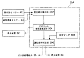
図2に、制御装置50Aの構成を示す。実圧縮比算出部502は、筒内圧センサー42で検出された圧縮前圧力(給気圧力)Ps、着火前圧縮圧力Pcと、給気温度センサー44で検出された給気温度Tsが入力され、これらの検出値から実圧縮比を算出する。
デポジット堆積量推定部504は、実圧縮比算出部502で算出された実圧縮比と、着火前圧縮圧力Pcと同一クランク角における設計圧縮比とを比較し、両者の偏差からシリンダ内のデポジット堆積量を推定する。
運転条件補正部506は、前記偏差が閾値を超えたとき、補正マップ508に基づいて、着火装置24の着火タイミングを補正する。
FIG. 2 shows the configuration of the
The deposit accumulation amount estimation unit 504 compares the actual compression ratio calculated by the actual compression ratio calculation unit 502 with the pre-ignition compression pressure Pc and the design compression ratio at the same crank angle, and determines the deposit accumulation in the cylinder from the deviation between the two. Estimate the amount.
The operating condition correction unit 506 corrects the ignition timing of the
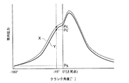
かかる構成において、本実施形態の燃焼制御手順を図3により説明する。実圧縮比算出部502では、筒内圧センサー42で検出された着火前圧縮圧力Pc及び給気圧力Psと、給気温度センサー44で検出された給気温度Tsとから、実圧縮比εを算出する(S10)。図4に示すように、給気圧力Psは、圧縮行程に入る前の吸入行程における筒内圧力である。着火前圧縮圧力Pcは、圧縮行程における着火前の任意のクランク角における圧縮圧力である。例えば、図4に示すように、上死点前−15°の圧縮圧力を選択する。
In this configuration, the combustion control procedure of this embodiment will be described with reference to FIG. The actual compression ratio calculation unit 502 calculates the actual compression ratio ε from the pre-ignition compression pressure Pc and the supply air pressure Ps detected by the in-cylinder pressure sensor 42 and the supply air temperature Ts detected by the supply
実圧縮比εの算出方法は、理想気体の断熱圧縮の状態式であるPVκ=一定の関係を用いる。この関係式から、次の式(1)を導くことができる。
Ps×Vsκ=Pc×Vcκ
ε=Vs/Vc=(Pc/Ps)1/κ (1)
ここで、Vsは圧縮前のシリンダ容積であり、Vcは圧縮行程における着火前のシリンダ容積であり、κは作動気体(ここでは燃焼ガス)の比熱比であり、εは実圧縮比である。筒内圧センサー42で検出したPc、Ps、及び給気温度TsとPc、Psに基づいて補正したκの値を式(1)に代入することで、実圧縮比εを算出できる。なお、筒内圧力のPc、Psは絶対圧力を用いる。
The calculation method of the actual compression ratio ε uses a constant relationship PV κ = constant, which is a state equation of adiabatic compression of an ideal gas. From this relational expression, the following expression (1) can be derived.
Ps × Vs κ = Pc × Vc κ
ε = Vs / Vc = (Pc / Ps) 1 / κ (1)
Here, Vs is the cylinder volume before compression, Vc is the cylinder volume before ignition in the compression stroke, κ is the specific heat ratio of the working gas (combustion gas here), and ε is the actual compression ratio. The actual compression ratio ε can be calculated by substituting the value κ corrected based on the Pc and Ps detected by the in-cylinder pressure sensor 42 and the supply air temperatures Ts and Pc and Ps into the equation (1). In-cylinder pressures Pc and Ps use absolute pressures.
また、設計圧縮比ε'は、上死点前−15°におけるシリンダ内容積Vc'の設計値と、下死点(−180°)におけるシリンダ内容積Vs'の設計値とから次の式(2)によって求めることができる。
ε'=Vs'/Vc' (2)
Further, the design compression ratio ε ′ is calculated from the design value of the cylinder internal volume Vc ′ at −15 ° before top dead center and the design value of the cylinder internal volume Vs ′ at bottom dead center (−180 °) by the following formula ( 2).
ε ′ = Vs ′ / Vc ′ (2)
図4に、燃焼室18にデポジット堆積がある場合の筒内圧力波形Xと、燃焼室18にデポジット堆積がない場合の筒内圧力波形Yとを摸式的に示している。即ち、デポジット堆積が増加するに従って、燃焼室18の容積が減少するため、筒内圧力が増加する傾向になる。従って、デポジット堆積がある場合の着火前圧縮圧力Pcは、デポジット堆積がない場合の設計上の着火前圧縮圧力Pc'より増加する。 FIG. 4 schematically shows an in-cylinder pressure waveform X when there is deposit accumulation in the combustion chamber 18 and an in-cylinder pressure waveform Y when there is no deposit accumulation in the combustion chamber 18. That is, as the deposit build-up increases, the volume of the combustion chamber 18 decreases, so that the in-cylinder pressure tends to increase. Therefore, the pre-ignition compression pressure Pc in the presence of deposit accumulation increases from the designed pre-ignition compression pressure Pc ′ in the absence of deposit accumulation.
図3に戻り、次に、デポジット堆積量推定部504で、算出した実圧縮比εと設計圧縮比ε'との偏差Δεを求め(S11)、偏差Δεを閾値と比較する(S12)。閾値は、排ガス性状が規制値を超えない限界値より余裕をもって設定されている。偏差Δεが閾値を超えていないときは、そのまま運転を継続する(S16)。偏差Δεが閾値を超えたときは、運転条件補正部506で、補正マップ508に基づいて、運転条件を補正する。即ち、着火装置24の着火タイミングの遅角量を増加する(S14)。図5に補正マップ508の一例を示す。図5において、補正曲線Zに沿って、実圧縮比εが設計圧縮比ε'と比べて増大したときは、着火タイミングを遅角する。かかる運転制御手順を運転サイクル毎(圧縮行程毎)に、且つシリンダ毎に連続的に繰り返す。
Returning to FIG. 3, the deposit accumulation amount estimation unit 504 obtains a deviation Δε between the calculated actual compression ratio ε and the design compression ratio ε ′ (S11), and compares the deviation Δε with a threshold value (S12). The threshold value is set with a margin from a limit value at which the exhaust gas property does not exceed the regulation value. If the deviation Δε does not exceed the threshold value, the operation is continued as it is (S16). When the deviation Δε exceeds the threshold value, the operating condition correction unit 506 corrects the operating condition based on the correction map 508. That is, the retard amount of the ignition timing of the
例えば、定置用ガスエンジン10において、設計圧縮比ε'が10.0であるとき、実圧縮比εとの偏差Δεの閾値を0.1に設定すると、実圧縮比εが10.1を超えないように運転制御される。 For example, in the stationary gas engine 10, when the design compression ratio ε ′ is 10.0 and the threshold value of the deviation Δε from the actual compression ratio ε is set to 0.1, the actual compression ratio ε exceeds 10.1. Operation is controlled so that there is no.
なお、本実施形態において、制御装置50Aによって、着火装置24の着火タイミングを制御するだけでなく、ガス供給電磁弁36の開度を制御して燃焼室18に供給される混合気の空燃比を制御するようにしてもよい。この空燃比制御の場合には、偏差Δεが閾値を超えたときには、空燃比を大きくするように、ガス供給電磁弁36の開度を閉側に制御して、排ガス性状、例えば排ガス中NOx量を確実に規制値以下になるように補正してもよい。以上のように、着火タイミング、および空燃比を補正することで、排ガス性状をより精度良く制御できる。
また、デポジット堆積量推定部504で算出して把握したデポジットの堆積状況は、表示装置52で表示される。
In the present embodiment, not only the ignition timing of the
The deposit accumulation state calculated and grasped by the deposit accumulation amount estimation unit 504 is displayed on the
本実施形態によれば、筒内圧センサー42及び給気温度センサー44を設けるだけの簡易かつ低コストな手段で、実圧縮比εを算出できる。また、実圧縮比εと設計圧縮比ε'との偏差Δεを監視するだけで、燃焼室18のデポジット堆積状況を把握できる。
そして、デポジットの堆積により排ガス性状が悪化した場合でも、制御装置50Aによって着火装置24の着火タイミングを補正し、必要とあれば、さらにガス供給電磁弁36の開度を調整することで空燃比を補正して、デポジット堆積による排ガス性状の変化を小さく抑えることができる。
According to this embodiment, the actual compression ratio ε can be calculated by a simple and low-cost means that simply provides the in-cylinder pressure sensor 42 and the supply
Even when the exhaust gas properties deteriorate due to deposit accumulation, the
そのため、図6(A)の点線で示すように、NOX規制値に対して余裕の少ない高効率設定(具体的には着火タイミングの進角、空燃比のリッチ化等)で運転可能となり、図6(B)の点線で示すように熱効率の高い運転が可能になる。なお、図6は、メンテナンス頻度を示す線図であり、(A)は排ガス中NOX量を縦軸に採り、(B)は熱効率を縦軸に採ったものである。
従って、燃料コスト等のランニングコストを節減できると共に、デポジット除去のためのメンテナンス間隔を広げることができるので、メンテナンスコストを節減できる。
Therefore, as shown by the dotted line in FIG. 6 (A), it becomes possible to operate with a high efficiency setting (specifically, ignition timing advancement, air-fuel ratio enrichment, etc.) with little margin with respect to the NO X regulation value, As shown by the dotted line in FIG. 6B, operation with high thermal efficiency becomes possible. Incidentally, FIG. 6 is a diagram showing the frequency of maintenance, (A) is taken on the vertical axis the amount of NO X in the exhaust gas, (B) are those taken on the vertical axis the heat efficiency.
Therefore, running costs such as fuel costs can be reduced, and the maintenance interval for removing deposits can be increased, so that maintenance costs can be reduced.
(実施形態2)
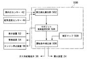
次に、本発明の第2実施形態を図7〜図9により説明する。本実施形態は、第1実施形態と同一の構成を有する定置用ガスエンジンに適用された例である。図7は本実施形態の制御装置50Bの構成を示す。制御装置50Bは、第1実施形態の制御装置50Aの構成に加えて、警報装置54及びエンジン停止装置56を付設したものである。警報装置54は、オペレータ及びその他の関係者に情報発信可能な監視室等の場所に設けられている。
(Embodiment 2)
Next, a second embodiment of the present invention will be described with reference to FIGS. The present embodiment is an example applied to a stationary gas engine having the same configuration as the first embodiment. FIG. 7 shows the configuration of the
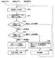
制御装置50Bによる燃焼制御手順を図8により説明する。まず、第1実施形態と同様に、圧縮圧力Pc、給気圧力Ps及び給気温度Tsからシリンダ12の実圧縮比εを算出する(S20)。次に、第1実施形態と同様に、実圧縮比εと同じクランク角における設計圧縮比ε'とを比較し、これらの偏差Δεを求め(S21)、偏差Δεを第1閾値と比較する(S22)。第1閾値は第1実施形態の閾値と同じ値であってもよいし、あるいは異なる値であってもよい。偏差Δεが第1閾値を超えていないときは、そのまま運転を継続する(S28)。
A combustion control procedure by the
偏差Δεが第1閾値を超えたときは、偏差Δεを第2閾値と比較する(S24)。第2閾値は第1閾値より大きな値であり、排ガス性状が規制値を超える限界値である。例えば、定置用ガスエンジン10の設計圧縮比が10.0であるとき、第1閾値を0.1とし、第2閾値を0.2と設定する。偏差Δε≦第2閾値であれば、補正マップ508に基づいて運転条件を補正する。即ち、着火タイミングの遅角量を増加する。同時に、警報装置54で警報を発令する(S26)。警報を発令したときは、次回メンテナンスで当該シリンダ12の燃焼室18を清掃する。偏差Δε>第2閾値であれば、当該シリンダ12を停止するか、又はエンジン全体を停止する(S30)。そして、早急に定置用ガスエンジン10を分解し点検する。かかる運転制御手順を運転サイクル毎(圧縮行程毎)に、且つシリンダ毎に連続的に繰り返す。
When the deviation Δε exceeds the first threshold, the deviation Δε is compared with the second threshold (S24). The second threshold value is a value larger than the first threshold value, and is a limit value where the exhaust gas property exceeds the regulation value. For example, when the design compression ratio of the stationary gas engine 10 is 10.0, the first threshold value is set to 0.1 and the second threshold value is set to 0.2. If the deviation Δε ≦ the second threshold value, the operating condition is corrected based on the correction map 508. That is, the retard amount of the ignition timing is increased. At the same time, an alarm is issued by the alarm device 54 (S26). When an alarm is issued, the combustion chamber 18 of the
本実施形態によれば、第1実施形態で得られる作用効果に加えて、デポジットの堆積状況に基づいて、シリンダ毎にメンテナンス時の燃焼室の清掃要否を的確に判断でき、メンテナンスコストを最小化できる。例えば、図9に示すように、デポジットの堆積量が多いプラントAと、デポジットの堆積量が少ないプラントBがあるとき、メンテナンス1の時点では、デポジット堆積量が第1閾値を超えたプラントのみを清掃するようにする。次に、メンテナンス2の時点では、プラントA及びBのデポジット堆積量が第1閾値を超えているので、プラントA及びBを清掃する。これによって、プラント毎に必要最小限の清掃回数とすることができる。 According to the present embodiment, in addition to the operational effects obtained in the first embodiment, it is possible to accurately determine whether or not the combustion chamber needs to be cleaned at the time of maintenance for each cylinder on the basis of the deposit accumulation state, thereby minimizing the maintenance cost. Can be For example, as shown in FIG. 9, when there is a plant A with a large amount of deposit and a plant B with a small amount of deposit, at the time of maintenance 1, only the plant whose deposit amount exceeds the first threshold is selected. Try to clean. Next, at the time of maintenance 2, since the deposit amount of the plants A and B exceeds the first threshold value, the plants A and B are cleaned. As a result, the minimum number of cleanings required for each plant can be achieved.
また、シリンダ毎にデポジット堆積状況を的確に監視でき、特定シリンダでの燃料系統や潤滑油系統等の不具合を早期に発見でき、機関損傷等の重大事故の発生をなくすことができる。 In addition, the deposit accumulation state can be accurately monitored for each cylinder, a failure such as a fuel system or a lubricating oil system in a specific cylinder can be detected at an early stage, and a serious accident such as engine damage can be eliminated.
(実施形態3)
次に、本発明の第3実施形態を図10により説明する。本実施形態では、運転サイクル毎(圧縮行程毎)の検出値の変動の影響を抑えるため、実圧縮比εを検出値の移動平均を用いて平均化するようにした例である。
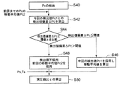
図10において、まず、着火前圧縮圧力Pcを検出する(S40)。次に、検出した着火前圧縮圧力Pc1と、前回までの演算サイクルでの移動平均の着火前圧縮圧力Pc2との検出値偏差ΔPcを算出する(S42)。この検出値偏差ΔPcを閾値と比較する(S44)。検出値偏差ΔPc≦閾値のとき、今回検出した着火前圧縮圧力Pc1を採用し、該着火前圧縮圧力Pc1を含めた移動平均値を算出する(S46)。一方、検出値偏差ΔPc>閾値のとき、今回検出した着火前圧縮圧力Pc1を不採用とし、前回までの移動平均値の着火前圧縮圧力Pc2を採用する(S48)。
(Embodiment 3)
Next, a third embodiment of the present invention will be described with reference to FIG. The present embodiment is an example in which the actual compression ratio ε is averaged using a moving average of detected values in order to suppress the influence of fluctuations in the detected values for each operation cycle (for each compression stroke).
In FIG. 10, first, the pre-ignition compression pressure Pc is detected (S40). Next, a detected value deviation ΔPc between the detected pre-ignition compression pressure Pc1 and the moving average pre-ignition compression pressure Pc2 in the previous calculation cycle is calculated (S42). This detected value deviation ΔPc is compared with a threshold value (S44). When the detected value deviation ΔPc ≦ the threshold, the pre-ignition compression pressure Pc1 detected this time is adopted, and a moving average value including the pre-ignition compression pressure Pc1 is calculated (S46). On the other hand, when the detected value deviation ΔPc> the threshold, the pre-ignition compression pressure Pc1 detected this time is not adopted, and the pre-ignition compression pressure Pc2 of the moving average value up to the previous time is adopted (S48).
次に、この着火前圧縮圧力Pcと別途検出した給気圧力Ps及び給気温度Tsとから実圧縮比εを算出する(S50)。算出した実圧縮比εを用い、図3に示す第1実施形態の制御手順、又は図8に示す第2実施形態の制御手順により、制御サイクルを繰り返す。 Next, the actual compression ratio ε is calculated from the pre-ignition compression pressure Pc, the separately detected supply air pressure Ps, and the supply air temperature Ts (S50). Using the calculated actual compression ratio ε, the control cycle is repeated according to the control procedure of the first embodiment shown in FIG. 3 or the control procedure of the second embodiment shown in FIG.
本実施形態によれば、着火前圧縮圧力Pcを検出する際に、移動平均値に対して検出値偏差の大きい検出値を除くことで、着火前圧縮圧力Pcの検出値の瞬間的なノイズや、一過性の異常燃焼を排除できる。そのため、運転中の微小変動を排除した信頼できる実圧縮比εを算出できる。 According to the present embodiment, when detecting the pre-ignition compression pressure Pc, by removing the detection value having a large detection value deviation with respect to the moving average value, instantaneous noise of the detection value of the pre-ignition compression pressure Pc or , Transient abnormal combustion can be eliminated. Therefore, it is possible to calculate a reliable actual compression ratio ε that eliminates minute fluctuations during operation.
なお、以上説明した例は、実圧縮比εを着火前圧縮圧力Pcの検出値の移動平均を用いて平均化するようにした例であるが、運転サイクル毎に算出された実圧縮比εの移動平均を用いて平均化し、これによって、瞬間的なノイズや一過性の異常燃焼の影響を排除するようにしてもよい。また、移動平均でなく、一定期間の実圧縮比εの最大値、最小差を排除するような手法によって瞬間的なノイズや一過性の異常燃焼の影響を排除するようにしてもよい。 The example described above is an example in which the actual compression ratio ε is averaged using the moving average of the detected values of the compression pressure Pc before ignition, but the actual compression ratio ε calculated for each operation cycle is A moving average may be used for averaging, thereby eliminating the effects of instantaneous noise and transient abnormal combustion. In addition, the influence of instantaneous noise and transient abnormal combustion may be eliminated by a method that eliminates the maximum value and the minimum difference of the actual compression ratio ε during a certain period instead of the moving average.
(実施形態4)
次に、本発明の第4実施形態を図11により説明する。本実施形態では、筒内圧センサー42のドリフトの影響を排除するため、着火前圧縮圧力Pcは、検出値そのものを使用せず、圧縮行程前の圧力との差分と、給気圧センサー48からの検出信号による給気圧力Psとに基づいて算出した絶対圧力を用いるようにしてもよい。
(Embodiment 4)
Next, a fourth embodiment of the present invention will be described with reference to FIG. In the present embodiment, in order to eliminate the influence of drift of the in-cylinder pressure sensor 42, the detected pressure itself is not used as the compression pressure Pc before ignition, and the difference from the pressure before the compression stroke is detected from the
図11に示すように、ガス噴射装置32の下流側給気管20に、燃焼室18内に流入する給気圧力を検出する給気圧センサー48を設け、実圧縮比算出部502では、給気圧センサー48によって検出した給気圧力Psを圧縮前圧力とし、そして、筒内圧センサー42によって検出した圧縮前圧力と着火前圧縮圧力との差分(ΔP)と給気圧センサー48によって検出した給気圧力Psとの加算より、着火前圧縮圧力(Pc=Ps+ΔP)の絶対圧力値を算出する。
この給気圧力Psと前記加算より算出した着火前圧縮圧力Pcを用いて実圧縮比εを算出する。
As shown in FIG. 11, a downstream air supply pipe 20 of the
The actual compression ratio ε is calculated using the supply pressure Ps and the pre-ignition compression pressure Pc calculated from the addition.
これによって、筒内圧センサー42自体が劣化等によって検出値がドリフトして正確な絶対圧力値を検出できなくなっても、筒内圧センサー42の検出値の差分(偏差)と給気圧力センサー48からの検出値とを用いて筒内圧力の着火前圧縮圧力(Pc=Ps+ΔP)の絶対圧力を算出し、着火前圧縮圧力Pcを用いることで、筒内圧センサー42のドリフトの影響を排除でき、信頼できる実圧縮比を算出できる。
As a result, even if the detected value drifts due to deterioration or the like in the cylinder pressure sensor 42 itself and an accurate absolute pressure value cannot be detected, the difference (deviation) between the detected value of the cylinder pressure sensor 42 and the
本発明によれば、簡易かつ低コストな手段でシリンダ内のデポジット堆積量を検出し、デポジット堆積量を抑える運転を行うことによって、排ガス性状を規制値以下に抑えることができる。本発明は、ガスエンジン、ディーゼルエンジン、ガソリンエンジン等、内燃機関全般に適用可能である。 According to the present invention, the exhaust gas property can be suppressed to a regulation value or less by detecting the deposit accumulation amount in the cylinder by a simple and low-cost means and performing the operation for suppressing the deposit accumulation amount. The present invention is applicable to all internal combustion engines such as a gas engine, a diesel engine, and a gasoline engine.
10A、10B 定置用ガスエンジン
12 シリンダ
14 ピストン
16 クランク軸
18 燃焼室18
20 給気管
22 排気管
24 着火装置
26 給気弁
28 排気弁
30 発電機
32 ガス噴射装置
34 ガス供給管
36 ガス供給電磁弁
38 副室
42 筒内圧センサー
44 給気温度センサー
46 クランク角センサー
48 給気圧センサー
50A、50B 制御装置
502 実圧縮比算出部
504 デポジット把握部
506 運転条件補正部
508 補正マップ
52 表示装置
54 警報装置
56 エンジン停止装置
Pc、Pc’、Pc1,Pc2 着火前圧縮圧力
Ps 圧縮前圧力(給気圧力)
Ts 給気温度
X 圧縮圧力(デポジット堆積あり)
Y 圧縮圧力(デポジット堆積なし)
Z 補正曲線
a 空気
g 燃料ガス
e 排ガス
ε 実圧縮比
ε’ 設計圧縮比
10A, 10B
20 Supply pipe 22
Ts Supply air temperature X Compression pressure (with deposit)
Y Compression pressure (no deposit buildup)
Z correction curve a Air g Fuel gas e Exhaust gas ε Actual compression ratio ε 'Design compression ratio
Claims (6)
該筒内圧センサーで検出された圧縮行程が開始されるクランク角における筒内圧力である圧縮前圧力Ps及び圧縮行程における着火前であって圧縮行程内での所定のクランク角における筒内圧力である着火前圧縮圧力Pcに基づいて実圧縮比εを、ε=(Pc/Ps) 1/κ (但しκは作動気体の比熱比)の算出式より算出する実圧縮比算出手段と、
圧縮行程が開始されるクランク角におけるシリンダ内容積Vs'の設計値と前記着火前圧縮圧力Pcの検出時のクランク角と同一のクランク角におけるシリンダ内容積Vc'の設計値とから設計圧縮比ε'を、ε'=Vs'/Vc'の算出式より算出して、前記実圧縮比εと前記設計圧縮比ε'とを比較して両者の偏差からシリンダ内のデポジット堆積量を推定するデポジット堆積量推定手段と、
前記偏差が閾値を超えたとき、内燃機関の運転条件を補正する運転条件補正手段と、を備え、
前記運転条件補正手段は、前記偏差が閾値を超えたとき、着火タイミングを遅角するように補正し、さらに、空燃比を大きくするように補正することを特徴とする内燃機関の燃焼制御装置。 An in-cylinder pressure sensor for detecting the pressure in the cylinder;
The pre-compression pressure Ps that is the in-cylinder pressure at the crank angle at which the compression stroke detected by the in-cylinder pressure sensor is started, and the in-cylinder pressure at a predetermined crank angle in the compression stroke before ignition in the compression stroke. An actual compression ratio calculation means for calculating an actual compression ratio ε based on the pre-ignition compression pressure Pc from a calculation formula of ε = (Pc / Ps) 1 / κ (where κ is the specific heat ratio of the working gas) ;
The design compression ratio ε is determined from the design value of the cylinder internal volume Vs ′ at the crank angle at which the compression stroke starts and the design value of the cylinder internal volume Vc ′ at the same crank angle as the crank angle at the time of detecting the pre-ignition compression pressure Pc. ′ Is calculated from the calculation formula of ε ′ = Vs ′ / Vc ′, the actual compression ratio ε is compared with the design compression ratio ε ′, and the deposit amount in the cylinder is estimated from the deviation between the two. Deposit amount estimation means;
When the deviation exceeds a threshold value, e Preparations and operating condition correcting means for correcting the operating condition of the internal combustion engine, and
When the deviation exceeds a threshold value, the operating condition correction means corrects the ignition timing to be retarded, and further corrects the air-fuel ratio to be increased .
該第1閾値より大きい第2閾値を超えたとき、対象シリンダが異常状態であると判定し、対象シリンダ又は内燃機関を停止する機関停止手段とをさらに備えることを特徴とする請求項1又は2に記載の内燃機関の燃焼制御装置。 An alarm device for issuing an alarm when the deviation exceeds a first threshold;
The engine further comprises engine stop means for determining that the target cylinder is in an abnormal state when a second threshold value greater than the first threshold value is exceeded, and stopping the target cylinder or the internal combustion engine. A combustion control device for an internal combustion engine according to claim 1.
圧縮行程が開始されるクランク角におけるシリンダ内容積Vs'の設計値と前記着火前圧縮圧力Pcの検出時のクランク角と同一のクランク角におけるシリンダ内容積Vc'の設計値とから設計圧縮比ε'を、ε'=Vs'/Vc'の算出式より算出して、前記実圧縮比εと前記設計圧縮比ε'とを比較し、両者の偏差からシリンダ内のデポジット堆積量を推定するデポジット堆積量推定工程と、
前記偏差が閾値を超えたとき、着火タイミングを遅角するように補正し、さらに、空燃比を大きくするように補正する運転条件補正工程とからなることを特徴とする内燃機関の燃焼制御方法。
The pre-compression pressure Ps, which is the in-cylinder pressure at the crank angle at which the compression stroke is started by the in-cylinder pressure sensor, and the pre- ignition compression pressure, which is the in-cylinder pressure at a predetermined crank angle in the compression stroke before ignition in the compression stroke. Pc is detected, and the actual compression ratio ε is calculated based on the pre-compression pressure and the pre-ignition compression pressure from the calculation formula of ε = (Pc / Ps) 1 / κ (where κ is the specific heat ratio of the working gas). An actual compression ratio calculation step;
The design compression ratio ε is determined from the design value of the cylinder internal volume Vs ′ at the crank angle at which the compression stroke starts and the design value of the cylinder internal volume Vc ′ at the same crank angle as the crank angle at the time of detecting the pre-ignition compression pressure Pc. 'Is calculated from the calculation formula of ε' = Vs' / Vc ', the actual compression ratio ε and the design compression ratio ε' are compared, and the deposit accumulation amount in the cylinder is estimated from the deviation between the two. Deposition amount estimation step;
A combustion control method for an internal combustion engine, comprising: an operating condition correcting step of correcting the ignition timing so as to be retarded when the deviation exceeds a threshold and further correcting to increase the air-fuel ratio .
Priority Applications (5)
| Application Number | Priority Date | Filing Date | Title |
|---|---|---|---|
| JP2012009542A JP5936367B2 (en) | 2012-01-20 | 2012-01-20 | Combustion control device and control method for internal combustion engine |
| EP13738376.6A EP2806147B1 (en) | 2012-01-20 | 2013-01-17 | Combustion control device and method for an internal combustion engine |
| PCT/JP2013/050855 WO2013108858A1 (en) | 2012-01-20 | 2013-01-17 | Combustion control device and control method for internal combustion engine |
| US14/362,799 US9157409B2 (en) | 2012-01-20 | 2013-01-17 | Combustion control device and control method for internal combustion engine |
| CN201380004161.1A CN103975154B (en) | 2012-01-20 | 2013-01-17 | The combustion control device of internal combustion engine and control method |
Applications Claiming Priority (1)
| Application Number | Priority Date | Filing Date | Title |
|---|---|---|---|
| JP2012009542A JP5936367B2 (en) | 2012-01-20 | 2012-01-20 | Combustion control device and control method for internal combustion engine |
Publications (2)
| Publication Number | Publication Date |
|---|---|
| JP2013148027A JP2013148027A (en) | 2013-08-01 |
| JP5936367B2 true JP5936367B2 (en) | 2016-06-22 |
Family
ID=48799281
Family Applications (1)
| Application Number | Title | Priority Date | Filing Date |
|---|---|---|---|
| JP2012009542A Active JP5936367B2 (en) | 2012-01-20 | 2012-01-20 | Combustion control device and control method for internal combustion engine |
Country Status (5)
| Country | Link |
|---|---|
| US (1) | US9157409B2 (en) |
| EP (1) | EP2806147B1 (en) |
| JP (1) | JP5936367B2 (en) |
| CN (1) | CN103975154B (en) |
| WO (1) | WO2013108858A1 (en) |
Families Citing this family (8)
| Publication number | Priority date | Publication date | Assignee | Title |
|---|---|---|---|---|
| JP5964877B2 (en) * | 2014-03-25 | 2016-08-03 | トヨタ自動車株式会社 | In-cylinder pressure sensor control device |
| DE112015002293T5 (en) * | 2014-06-17 | 2017-02-23 | Scania Cv Ab | Method and device for compression diagnosis of an internal combustion engine |
| CN106337743B (en) * | 2015-07-10 | 2019-07-19 | 本田技研工业株式会社 | The control device of internal combustion engine |
| CN106337750B (en) * | 2015-07-10 | 2019-07-19 | 本田技研工业株式会社 | The control device of internal combustion engine |
| JP2017227198A (en) * | 2016-06-24 | 2017-12-28 | トヨタ自動車株式会社 | Control device of diesel engine |
| DE102017216121A1 (en) * | 2017-09-13 | 2019-03-14 | Volkswagen Aktiengesellschaft | Method for operating an internal combustion engine and internal combustion engine |
| CN111397833B (en) * | 2020-04-22 | 2021-06-04 | 中国科学院力学研究所 | High-enthalpy supersonic wind tunnel airflow generation method |
| CN113047965B (en) * | 2021-04-02 | 2022-05-03 | 北京交通大学 | Method for determining working compression ratio of reciprocating internal combustion engine |
Family Cites Families (23)
| Publication number | Priority date | Publication date | Assignee | Title |
|---|---|---|---|---|
| US3680305A (en) * | 1970-09-28 | 1972-08-01 | Raymond S Miller | Clean combustion engine system |
| JPS6047836A (en) * | 1983-08-25 | 1985-03-15 | Toyota Motor Corp | Method of controlling air-fuel ratio of internal combustion engine |
| JPS61145365A (en) * | 1984-12-17 | 1986-07-03 | Mazda Motor Corp | Ignition timing control device of engine |
| JPH084562A (en) | 1994-06-17 | 1996-01-09 | Isuzu Ceramics Kenkyusho:Kk | Multi-fuel engine |
| JPH08261033A (en) | 1995-03-23 | 1996-10-08 | Nissan Motor Co Ltd | Deposit detection device for engine |
| JPH0996238A (en) | 1995-10-03 | 1997-04-08 | Hitachi Ltd | Engine combustion control device |
| JPH1136922A (en) * | 1997-07-25 | 1999-02-09 | Hitachi Ltd | Controller of cylinder injection type internal combustion engine |
| JP4370338B2 (en) | 2001-03-30 | 2009-11-25 | 三菱重工業株式会社 | Combustion diagnosis / control device and combustion diagnosis / control method for internal combustion engine |
| JP2003343296A (en) * | 2002-03-20 | 2003-12-03 | Honda Motor Co Ltd | Compression ratio variable engine |
| JP2004092574A (en) | 2002-09-03 | 2004-03-25 | Mitsubishi Heavy Ind Ltd | Gas engine equipped with auxiliary scavenging device |
| JP2005048621A (en) | 2003-07-31 | 2005-02-24 | Toyota Motor Corp | Compression ratio calculation device of internal combustion engine, compression ratio calculation method, control device of internal combustion engine and its control method |
| JP3886949B2 (en) | 2003-08-20 | 2007-02-28 | 三菱重工業株式会社 | Gas engine fuel control device and fuel control method |
| JP2005140054A (en) * | 2003-11-07 | 2005-06-02 | Toyota Motor Corp | Control device for internal combustion engine |
| US7533650B2 (en) * | 2004-04-07 | 2009-05-19 | Mack Trucks, Inc. | Emission control for an internal combustion engine |
| JP4835076B2 (en) * | 2005-01-17 | 2011-12-14 | トヨタ自動車株式会社 | Control device and control method for internal combustion engine |
| US7272487B2 (en) * | 2005-07-14 | 2007-09-18 | Ford Global Technologies, Llc | Method for monitoring combustion stability of an internal combustion engine |
| JP4367439B2 (en) * | 2006-05-30 | 2009-11-18 | トヨタ自動車株式会社 | Spark ignition internal combustion engine |
| JP5332645B2 (en) * | 2008-03-03 | 2013-11-06 | 日産自動車株式会社 | In-cylinder direct injection internal combustion engine |
| JP2009264176A (en) * | 2008-04-23 | 2009-11-12 | Yanmar Co Ltd | Gas engine control device |
| JP2010071126A (en) | 2008-09-17 | 2010-04-02 | Nissan Motor Co Ltd | Fuel injection control device for direct-injection internal combustion engine |
| DE102008044329A1 (en) * | 2008-12-03 | 2010-06-10 | Robert Bosch Gmbh | Real compression ratio determining method for cylinder of e.g. Otto-engine, has determining real compression ratio based on geometrical compression ratio, calculated and real cylinder pressures using control device |
| JP2010221751A (en) * | 2009-03-19 | 2010-10-07 | Toyota Motor Corp | Hybrid car |
| US20120160217A1 (en) * | 2009-09-11 | 2012-06-28 | Toyota Jidosha Kabushiki Kaisha | Combustion pressure controller |
-
2012
- 2012-01-20 JP JP2012009542A patent/JP5936367B2/en active Active
-
2013
- 2013-01-17 CN CN201380004161.1A patent/CN103975154B/en not_active Expired - Fee Related
- 2013-01-17 EP EP13738376.6A patent/EP2806147B1/en not_active Not-in-force
- 2013-01-17 US US14/362,799 patent/US9157409B2/en not_active Expired - Fee Related
- 2013-01-17 WO PCT/JP2013/050855 patent/WO2013108858A1/en active Application Filing
Also Published As
| Publication number | Publication date |
|---|---|
| CN103975154A (en) | 2014-08-06 |
| JP2013148027A (en) | 2013-08-01 |
| US20140331971A1 (en) | 2014-11-13 |
| CN103975154B (en) | 2016-11-16 |
| EP2806147A1 (en) | 2014-11-26 |
| EP2806147B1 (en) | 2017-09-06 |
| EP2806147A4 (en) | 2016-11-16 |
| WO2013108858A1 (en) | 2013-07-25 |
| US9157409B2 (en) | 2015-10-13 |
Similar Documents
| Publication | Publication Date | Title |
|---|---|---|
| JP5936367B2 (en) | Combustion control device and control method for internal combustion engine | |
| EP2700804B1 (en) | Gas engine, gas engine control apparatus, and gas engine control method | |
| JP5191983B2 (en) | Diagnostic device for internal combustion engine | |
| JP4100346B2 (en) | Engine fuel injection control device | |
| US7225800B2 (en) | Engine controller | |
| JP4700079B2 (en) | Device for determining an air-fuel ratio imbalance between cylinders | |
| RU2556030C1 (en) | Control device for internal combustion engine | |
| WO2011099405A1 (en) | Fuel injection control device and method for diesel engine | |
| US8756984B2 (en) | Abnormality diagnosis apparatus for engine control system | |
| US9010303B2 (en) | System and method of detecting hydraulic start-of-injection | |
| US8256281B2 (en) | Fuel property determination apparatus for internal combustion engine | |
| JP2007315193A (en) | Air-fuel ratio detecting device of internal combustion engine | |
| JP4387384B2 (en) | Control device for internal combustion engine | |
| JP4830986B2 (en) | Control device for internal combustion engine | |
| WO2013084309A1 (en) | Control device for internal combustion engine | |
| JP2012145059A (en) | Combustion control method and apparatus for internal combustion engine | |
| JP6287936B2 (en) | Fuel spray abnormality determination device for in-cylinder injection type diesel engine | |
| JP4705866B2 (en) | Control device for internal combustion engine | |
| JP5614320B2 (en) | Control device for internal combustion engine | |
| JP2004092427A (en) | Output control device for internal combustion engine | |
| JP2013142382A (en) | Abnormality determination device of internal-combustion engine |
Legal Events
| Date | Code | Title | Description |
|---|---|---|---|
| A621 | Written request for application examination |
Free format text: JAPANESE INTERMEDIATE CODE: A621 Effective date: 20140715 |
|
| A131 | Notification of reasons for refusal |
Free format text: JAPANESE INTERMEDIATE CODE: A131 Effective date: 20151002 |
|
| A521 | Request for written amendment filed |
Free format text: JAPANESE INTERMEDIATE CODE: A523 Effective date: 20151130 |
|
| TRDD | Decision of grant or rejection written | ||
| A01 | Written decision to grant a patent or to grant a registration (utility model) |
Free format text: JAPANESE INTERMEDIATE CODE: A01 Effective date: 20160415 |
|
| A61 | First payment of annual fees (during grant procedure) |
Free format text: JAPANESE INTERMEDIATE CODE: A61 Effective date: 20160510 |
|
| R151 | Written notification of patent or utility model registration |
Ref document number: 5936367 Country of ref document: JP Free format text: JAPANESE INTERMEDIATE CODE: R151 |