JP5934681B2 - Light decoration equipment - Google Patents
Light decoration equipment Download PDFInfo
- Publication number
- JP5934681B2 JP5934681B2 JP2013163083A JP2013163083A JP5934681B2 JP 5934681 B2 JP5934681 B2 JP 5934681B2 JP 2013163083 A JP2013163083 A JP 2013163083A JP 2013163083 A JP2013163083 A JP 2013163083A JP 5934681 B2 JP5934681 B2 JP 5934681B2
- Authority
- JP
- Japan
- Prior art keywords
- light
- lens
- outer lens
- light emitting
- inner lens
- Prior art date
- Legal status (The legal status is an assumption and is not a legal conclusion. Google has not performed a legal analysis and makes no representation as to the accuracy of the status listed.)
- Active
Links
- 238000005034 decoration Methods 0.000 title claims description 41
- 238000009792 diffusion process Methods 0.000 claims description 26
- 230000002093 peripheral effect Effects 0.000 claims description 25
- 230000007423 decrease Effects 0.000 claims description 4
- 230000001678 irradiating effect Effects 0.000 claims description 4
- 230000003287 optical effect Effects 0.000 claims description 2
- 230000035699 permeability Effects 0.000 claims description 2
- 239000000758 substrate Substances 0.000 description 12
- 230000005540 biological transmission Effects 0.000 description 3
- 230000008878 coupling Effects 0.000 description 3
- 238000010168 coupling process Methods 0.000 description 3
- 238000005859 coupling reaction Methods 0.000 description 3
- 239000012466 permeate Substances 0.000 description 3
- 239000000853 adhesive Substances 0.000 description 2
- 230000001070 adhesive effect Effects 0.000 description 2
- 238000002834 transmittance Methods 0.000 description 2
- XLYOFNOQVPJJNP-UHFFFAOYSA-N water Substances O XLYOFNOQVPJJNP-UHFFFAOYSA-N 0.000 description 2
- 230000003247 decreasing effect Effects 0.000 description 1
- 238000010586 diagram Methods 0.000 description 1
- 230000000694 effects Effects 0.000 description 1
- 230000003760 hair shine Effects 0.000 description 1
- 239000000463 material Substances 0.000 description 1
- 239000000203 mixture Substances 0.000 description 1
- 230000011218 segmentation Effects 0.000 description 1
- 239000007921 spray Substances 0.000 description 1
- 230000001360 synchronised effect Effects 0.000 description 1
Images


Description
本発明は、光装飾装置に関するものである。 The present invention relates to a light decoration device.
アミューズメントの分野では、炎などを模して表現する装飾装置が知られている。例えば、特許文献1で開示される光装飾装置は、複数の発光素子31〜33を配列した発光部4と、発光素子に対向した表面に微細な光反射部材が形成された回転可能な円筒状部材2と、円筒状部材2の表面で反射した光を拡散させるリアースクリーン部5とを備えており、リアースクリーン部5で炎を表現している。
In the amusement field, decorative devices that imitate flames and the like are known. For example, the light decoration device disclosed in Patent Document 1 includes a light-emitting section 4 in which a plurality of light-emitting elements 31 to 33 are arranged, and a rotatable cylindrical shape in which a fine light-reflecting member is formed on a surface facing the light-emitting elements. The
しかしながら、特許文献1の構成は、単に下側に配置された複数の発光素子の光のみを円筒状部材2で反射してスクリーンに投射する構成であるため、単調な光装飾となってしまう虞がある。また、分散配置された発光素子からのそれぞれの光を円筒状部材2の外周面で反射してそのままスクリーンに投射するため、スクリーンで光のムラが生じる虞もある。
However, since the configuration of Patent Document 1 is a configuration in which only light from a plurality of light emitting elements disposed on the lower side is reflected by the
本発明は、上述した課題を解決するためになされたものであり、極端な光のムラが生じにくく、より複雑な光装飾が可能な光装飾装置を提供することを目的とする。 The present invention has been made to solve the above-described problems, and an object thereof is to provide a light decoration device that is less likely to cause extreme light unevenness and that allows more complex light decoration.
本発明は、光透過性を有し、所定の回転軸を中心として回転可能なインナーレンズと、
光透過性を有し、前記インナーレンズの回転半径方向外側に所定の間隔を隔てて配置され所定の回転軸を中心として回転可能なアウターレンズと、
前記インナーレンズ及びアウターレンズを一体的又はそれぞれ独立して回転させる駆動源と、
前記アウターレンズの回転半径方向外側において前記アウターレンズから離間した位置に配置される拡散部材と、
前記インナーレンズに向けて光を照射する第一発光手段と、
前記アウターレンズに向けて光を照射する第二発光手段と、
を有し、
前記インナーレンズの回転軸の方向を上下方向とし、当該回転軸と直交する所定方向を前後方向としたとき、
前記第一発光手段は、前記インナーレンズの上方又は下方に配置され、且つ前記上下方向に沿って前記インナーレンズを透過する光を照射する構成となっており、
前記第二発光手段は、前記アウターレンズの後方において前記アウターレンズの周壁部と対向して配置され且つ前記アウターレンズ及び前記インナーレンズを透過するように前方側に光を照射する構成となっており、
前記第一発光手段から前記インナーレンズに向けて照射された光、及び前記第二発光手段から前記アウターレンズに向けて照射された光が、少なくとも前記アウターレンズの周方向における所定範囲内で前記拡散部材を介して外部に照射される構成となっていることを特徴とする。
The present invention comprises an inner lens having light transparency and rotatable about a predetermined rotation axis;
An outer lens having light permeability, arranged at a predetermined interval on the outer side in the rotational radius direction of the inner lens, and rotatable about a predetermined rotation axis;
A drive source for rotating the inner lens and the outer lens integrally or independently;
A diffusing member disposed at a position away from the outer lens on the outer side in the rotational radius direction of the outer lens;
First light emitting means for irradiating light toward the inner lens;
Second light emitting means for irradiating light toward the outer lens;
Have
When the direction of the rotation axis of the inner lens is the vertical direction, and the predetermined direction orthogonal to the rotation axis is the front-rear direction,
The first light emitting means is arranged above or below the inner lens and irradiates light that passes through the inner lens along the vertical direction.
The second light emitting means is arranged behind the outer lens so as to face the peripheral wall portion of the outer lens and irradiates light on the front side so as to pass through the outer lens and the inner lens. ,
The light emitted from the first light emitting means toward the inner lens and the light emitted from the second light emitting means toward the outer lens are diffused at least within a predetermined range in the circumferential direction of the outer lens. It is the structure which is irradiated outside through a member.
本発明では、所定の回転軸を中心として回転可能な光透過性を有するインナーレンズ及びアウターレンズを設けており、第一発光手段によりインナーレンズに向けて光を照射し、第二発光手段によりアウターレンズに向けて光を照射する構成となっている。このように、内外に二種類のレンズを設け、各レンズに対して別々の発光手段により光を当てているため、インナーレンズとアウターレンズとで異なる装飾態様を生じさせることができる。特に、このように各レンズからのそれぞれ別種の光が、拡散部材の所定領域(周方向所定範囲内)を通って拡散しつつ外部に照射されるため、この所定範囲内では、二種類の光が混ざり合ったより複雑な光が発生することになる。 In the present invention, there are provided an inner lens and an outer lens having light transmissibility that can rotate about a predetermined rotation axis, light is emitted toward the inner lens by the first light emitting means, and the outer lens is irradiated by the second light emitting means. It is the structure which irradiates light toward a lens. Thus, since two types of lenses are provided inside and outside and light is applied to each lens by separate light emitting means, different decoration modes can be generated between the inner lens and the outer lens. In particular, since different types of light from each lens are radiated to the outside while diffusing through a predetermined region (within a predetermined range in the circumferential direction) of the diffusing member in this way, two types of light are emitted within this predetermined range A more complex light that is mixed with each other will be generated.
また、本発明では、前記インナーレンズの軸線方向の一端側は複数に分割され、それらの分割面部が前記インナーレンズの回転軸を囲んで配置されており、少なくとも隣り合う前記分割面部の前記軸線方向での高さが異なっており、前記インナーレンズの回転に応じて、前記第一発光手段の光が前記分割面部に照射する構成となっていてもよい。この構成では、インナーレンズの回転に応じて、第一発光手段からの光が複数の分割面部にそれぞれ入射することになる。従って、インナーレンズ側では、異なる高さで第一発光手段からの光の反射光或いは屈折光を生じさせることができる。つまり、異なる高さの分割面(分割面部の外面)が複数あるため、光が拡散或いは屈曲する位置を多数設定することができ、発光態様を多様化することができる。 Further, in the present invention, one end side in the axial direction of the inner lens is divided into a plurality of parts, and the divided surface portions are disposed so as to surround the rotation axis of the inner lens, and at least the axial direction of the adjacent divided surface portions is the axial direction. The height may be different, and the split surface portion may be irradiated with light from the first light emitting means according to the rotation of the inner lens. In this configuration, light from the first light emitting unit is incident on each of the plurality of divided surface portions according to the rotation of the inner lens. Therefore, on the inner lens side, reflected light or refracted light from the first light emitting means can be generated at different heights. That is, since there are a plurality of dividing surfaces having different heights (outer surfaces of the dividing surface portions), a large number of positions where light is diffused or bent can be set, and the light emission modes can be diversified.
この場合、例えば、複数の前記分割面部は、前記インナーレンズの回転軸を中心とする周方向において所定の起点位置から1周の範囲で、前記周方向に進むにつれて漸次高さが大きく又は小さくなる螺旋階段状となっていてもよい。この構成では、インナーレンズの上面部に高さの異なる分割面(分割面部の外面)をより多く生じさせることができ、一層複雑な表示が可能となる。 In this case, for example, the plurality of dividing surface portions gradually increase or decrease as they progress in the circumferential direction within a range from a predetermined starting position in the circumferential direction around the rotation axis of the inner lens. It may be a spiral staircase. In this configuration, more divided surfaces (outer surfaces of the divided surface portions) having different heights can be generated on the upper surface portion of the inner lens, and more complicated display is possible.
また、本発明では、前記アウターレンズの外側には、少なくとも前記アウターレンズの回転半径方向外側の位置で前記第二発光手段を保持する保持部材が設けられ、前記第二発光手段は、前記アウターレンズの回転半径方向外側において前記アウターレンズの外周面を構成する周壁部と対向して配置され且つ前記アウターレンズを透過して前記アウターレンズに対し当該第二発光手段側とは反対側に光を照射する構成となっており、前記保持部材には、前記アウターレンズの周方向において前記第二発光手段の両側の位置に、前記アウターレンズの前記周壁部に向かって凸となる一対のリブが形成されていてもよい。この構成では、第二発光手段からの光をアウターレンズの周壁部に照射し、アウターレンズを透過させるように反対側に装飾光を生じさせることができる。特に、一対のリブを第二発光手段の幅方向両側に配置しているため、第二発光手段からの光をよりアウターレンズ側に集中させて照射することができる。 Further, in the present invention, a holding member that holds the second light emitting unit at least at a position outside the rotational radius of the outer lens is provided outside the outer lens, and the second light emitting unit includes the outer lens. Is disposed opposite to the outer peripheral surface of the outer lens in the radial direction of the outer lens, and is disposed so as to pass through the outer lens and irradiate the outer lens with light on the side opposite to the second light emitting means side. The holding member is formed with a pair of ribs protruding toward the peripheral wall portion of the outer lens at positions on both sides of the second light emitting means in the circumferential direction of the outer lens. It may be. In this configuration, it is possible to irradiate the peripheral wall portion of the outer lens with the light from the second light emitting means, and to generate decorative light on the opposite side so as to transmit the outer lens. In particular, since the pair of ribs are arranged on both sides in the width direction of the second light emitting means, the light from the second light emitting means can be more concentrated and irradiated on the outer lens side.
この場合、例えば前記一対のリブの前記第二発光手段側の内面は、白色面又は鏡面として構成されているとよい。この構成によれば、第二発光手段からの光が横に漏れ出すことを抑えて、よりアウターレンズ側に光を集めることができる。 In this case, for example, the inner surfaces of the pair of ribs on the second light emitting means side may be configured as white surfaces or mirror surfaces. According to this configuration, the light from the second light emitting means can be prevented from leaking sideways, and the light can be collected more on the outer lens side.
また、本発明では、前記インナーレンズの回転軸の方向を上下方向とし、当該回転軸と直交する所定方向を前後方向としたとき、前記第一発光手段は、前記インナーレンズの上方又は下方に配置され、且つ前記上下方向に沿って前記インナーレンズを透過する光を照射する構成となっており、前記第二発光手段は、前記アウターレンズの後方において前記アウターレンズの周壁部と対向して配置され且つ前記アウターレンズ及び前記インナーレンズを透過するように前方側に光を照射する構成となっているとよい。このようにすることで、向きが大きく異なる第一発光手段及び第二発光手段からの光をインナーレンズ及びアウターレンズ付近に集めつつそれぞれ照射させ、より複雑な光を生じさせやすくなる。 Further, in the present invention, when the direction of the rotation axis of the inner lens is the vertical direction and the predetermined direction orthogonal to the rotation axis is the front-rear direction, the first light emitting means is disposed above or below the inner lens. And is configured to irradiate light that passes through the inner lens along the vertical direction, and the second light emitting means is disposed behind the outer lens and facing the peripheral wall portion of the outer lens. And it is good to have a structure which irradiates light to the front side so that the said outer lens and the said inner lens may permeate | transmit. By doing so, light from the first light-emitting means and the second light-emitting means whose directions are greatly different from each other are irradiated in the vicinity of the inner lens and the outer lens, and more complicated light is easily generated.
また、本発明では、前記拡散部材は、前記アウターレンズの周囲に少なくとも部分的に配置されるシート状に形成され、且つ前記アウターレンズの回転軸の方向に対して傾斜した凹状又は凸状の線状部が、所定間隔ごとに形成されており、前記線状部は、前記アウターレンズの回転方向に進むにつれて下位置となるように傾斜しているとよい。このようにすることで、アウターレンズの回転に応じて線状部への光の入射位置、入射高さ等が変化させることができ、光の揺らぎや緩やかな移動を生じさせやすくなる。 In the present invention, the diffusing member is formed in a sheet shape at least partially arranged around the outer lens, and is a concave or convex line inclined with respect to the direction of the rotation axis of the outer lens. It is preferable that the shape portions are formed at predetermined intervals, and the linear portions are inclined so as to be in a lower position as they proceed in the rotation direction of the outer lens. By doing so, it is possible to change the incident position, incident height, and the like of the light to the linear portion according to the rotation of the outer lens, and it is easy to cause light fluctuation and gentle movement.
[第1実施形態]
以下、本発明に係る光装飾装置を具現化した第1実施形態について、図面を参照して説明する。
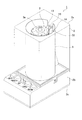
図1に示す光装飾装置1は、遊技機やゲーム機などのアミューズメント装置や、店舗などに設置される装飾物などとして構成されるものであり、複数の発光手段からの光を回転する複数のレンズ体で変化させることにより例えば現実の炎に近い表示を行い得るように構成されている。
[First embodiment]
Hereinafter, a first embodiment in which a light decoration device according to the present invention is embodied will be described with reference to the drawings.
A light decoration device 1 shown in FIG. 1 is configured as an amusement device such as a game machine or a game machine, or a decoration installed in a store or the like. For example, a display close to an actual flame can be performed by changing the lens body.
光装飾装置1は、主に、光透過性を有するインナーレンズ20と、光透過性を有すると共にインナーレンズ20の外側に所定の間隔を隔てて配置されるアウターレンズ30とを備え、所定の回転軸A1を中心として回転可能に構成された回転体3と、回転軸A1を中心として回転体3を回転させる駆動源7と、回転体3の回転半径方向外側において回転体3から離間した位置に配置されるシート状の拡散部材としての拡散シート5と、インナーレンズ20に向けて光を照射する第一発光手段としての第一光源部11と、アウターレンズ30に向けて光を照射する第二発光手段としての第二光源部12と、を有している。そして、第一光源部11からインナーレンズ20に向けて照射された光、及び第二光源部12からアウターレンズ30に向けて照射された光が、少なくとも回転体3の周方向における所定範囲内で拡散シート5を介して当該光装飾装置1の外部に照射される構成となっている。「所定範囲」は、様々に設定できるが、例えば、ケース2を外したときに正面側(前方側)から視認できる範囲(拡散シート5において、回転軸A1よりも前位置の範囲)であってもよく、これよりも狭い範囲、或いは広い範囲であってもよい。
The light decoration device 1 mainly includes an
なお、本構成では、回転軸A1の方向を上下方向とし、回転体3の回転軸A1と直交する所定方向を前後方向とし、回転軸A1の方向及び前後方向と直交する方向を幅方向とする。具体的には、第二光源部12を構成する発光素子12aの発光面と直交する方向が前後方向となっており、第二光源部12と回転体3が向かい合う方向が前後方向となっている。また、回転軸A1の方向が軸線方向の一例に相当する。なお、本構成では、回転軸A1(回転軸線)が、インナーレンズ20の回転軸にもなっており、アウターレンズ30の回転軸にもなっている。
In this configuration, the direction of the rotation axis A1 is the vertical direction, the predetermined direction orthogonal to the rotation axis A1 of the
光装飾装置1の外殻をなすケース2は、透明な上ケース2aと、この上ケース2aの下に配置される下ケース2bと、この下ケース2bの下側を閉塞する底壁部2cとによって構成されている。図3のように、下ケース2bは、後述する回転体3を回転可能に支持する部分であり、具体的には、後述する駆動源7を収容しつつ保持することで、この駆動源7によって回転体3の下端側を支持している。また、上ケース2aは、回転体3及び拡散シート5を取り囲むと共に、回転体3の上端側を回転可能に支持している。なお、図1では、上ケース2aの上壁部を省略して示している。
The
図3、図5、図6のように、本構成では、回転体3の中心をなすインナーレンズ20及びアウターレンズ30の上端部に連結される構成で円板状の上方連結部33が設けられており、インナーレンズ20及びアウターレンズ30の下端部に連結される構成で光透過性を有する円板状の下方連結部37が設けられている。そして、上方連結部33には回転体3の回転軸A1の方向に沿って上方に軸部3aが突出しており、この軸部3aが上ケース2aの上壁部によって回転可能に支持されている。また、下方連結部37には回転体3の回転軸A1の方向に沿って下方に軸部3bが突出しており、この軸部3bが下ケース2bの上壁部に回転可能に支持され、回転体3がケース2に回転可能に支持される。そして、この軸部3bに下ケース2bに収容された駆動源7の駆動軸7aが連結されている。
As shown in FIGS. 3, 5, and 6, in this configuration, a disk-shaped
回転体3は、全体として円柱状に構成されており、回転軸A1付近の中心部には、光透過性を有する上下に長いインナーレンズ20が配置されている。また、インナーレンズ20の外側には、インナーレンズ20の周壁部の周囲を所定の間隔を隔てて取り囲むように光透過性のアウターレンズ30が配置されている。
The
インナーレンズ20は回転軸A1付近が空洞状の中空形状となっており、下端部に所定の間隔で形成された突起が上述の下方連結部37に形成された透孔に嵌合して連結されている。また、インナーレンズ20の上端部は、図3に示すように上方連結部33に固定されることなく、上方連結部33の下方にある程度の距離を隔てて配置されている。
The
図4及び図5に示すように、インナーレンズ20の上面部22は平面視した形状が回転軸A1を中心とする円環状となっており、図4のように平面視したときの上面部22の内縁部及び上面部22の外縁部は、回転軸A1を中心とする円形となっている。
As shown in FIGS. 4 and 5, the
そして、図3、図4、図5、図6のように、インナーレンズの一端側(上端側)に設けられた上面部22は、複数に分割され、それら分割された各部分(分割上面部22a)が回転軸A1を囲んで環状に並ぶように配置されている。そして、複数の分割上面部22aは、「分割面部」の一例に相当し、高さ及び回転軸A1に対する傾斜状態がそれぞれ異なっており、回転体3の回転に応じて、複数の分割上面部22aが第一光源部11の投光経路を順番に通るように回転する構成となっている。具体的には、複数の分割上面部22aは、回転軸A1を中心とする周方向に進むにつれて高さが漸次大きく又は小さくなる螺旋階段状となっている。
As shown in FIGS. 3, 4, 5, and 6, the
アウターレンズ30は、インナーレンズ20が内部に収容される中空筒形状となっており、下端部は下面に形成された突起が上述の下方連結部37に形成された切欠きに嵌合して連結され、上端部が環状蓋35を介して上述の上方連結部33に連結されている。具体的には、アウターレンズ30は、3つの炎アウター(3つの要素部材30a、30b、30c)を環状蓋35に接着して一体化した構成となっている。そして、この環状蓋35の上面に形成された突起が上方連結部33に形成された切欠きに嵌合して連結されている。なお、このようにせずに、環状蓋35を省略し、環状蓋35の突起に相当する部分を3つの炎アウター(3つの要素部材30a、30b、30c)に設けて、3つの要素部材30a、30b、30cを直接上方連結部33と連結するようにしてもよい。
The
また、アウターレンズ30の外周面を構成する周壁部32は、多数の凹凸により複雑な形状に形成されており、この凹凸としては、例えば回転軸A1の方向に対して傾斜した溝状の部分や、山状の部分などにより形成されている。なお、本実施形態では、アウターレンズ30は3つの要素部材30a、30b、30cにより構成され、互いに組み付けることにより中空筒形状としている。
Moreover, the
図3等に示すように、回転体3を駆動する駆動源7は、駆動軸7a(回転軸部)を回転可能な公知のモータによって構成されており、例えば、駆動軸7aの上方に連結される回転体3を定常回転するように構成されている。
As shown in FIG. 3 and the like, the drive source 7 that drives the
図3、図5、図6、図7のように、第一光源部11は、複数の発光素子11a(例えば赤色のLED)によって構成されており、インナーレンズ20を透過するようにインナーレンズ20の下方に配置され、インナーレンズ20に向けて上方側に光を照射する構成となっている。これら発光素子11aは、中心部に孔部39が形成された円形状の基板B1の上面部に実装されており、いずれも発光面を上方側(インナーレンズ20側)に向けた構成で配置されている。
As shown in FIGS. 3, 5, 6, and 7, the first
これら発光素子11aは、図7のように回転軸A1を中心とする周方向に所定の間隔で環状に並んでおり、いずれも上方側に光を照射するようになっている。インナーレンズ20は、このように環状に配置された発光素子11aの円形配列の上方に下方連結部37を介して位置しており、回転体3がどの回転位置にあるときでも、全ての発光素子11aとインナーレンズ20の下端面とが常に対向するようになっている。また、基板B1は、下ケース2b内の所定位置に形成された凹部に収容されてビス等により固定され、基板B1の孔部39に下方連結部37の軸部3bが挿入される構成で配置されている。
These
図3、図5、図6、図7のように、第二光源部12は、複数の発光素子12a(例えば赤色のLED)によって構成されており、回転体3の後方においてアウターレンズ30の周壁部32と対向するように所定の間隔離間して配置され且つアウターレンズ30を透過するように前方側に光を照射する構成となっている。図3、図4に示すように、回転体3の後方側には、上下に延びると共に前後方向を厚さ方向とする縦長の基板B2が配置されており、この基板B2の前面側に複数の発光素子12aが実装されている。図4、図5に示す例では、複数の発光素子12aが基板B2に2列に千鳥状に配列されており、いずれの発光素子12aも、アウターレンズ30の周壁部32に向けて光を照射するようになっている。また、基板B2は、下ケース2b上面の所定位置にビス等により固定される基板取付部材15(基板取付部材15は、保持部材の一例に相当)に設けられる。なお、基板取付部材15に対する基板B2の取り付けは、ビス等の連結部材によって固定してもよく、接着剤等の接着媒体によって固定してもよい。或いは、基板取付部材15に形成された突起等を基板B2に嵌合させるような固定構造であってもよい。図3、図4のように、基板取付部材15は、上下に長手状に延びると共にアウターレンズ30の周壁部32と対向した形態で下ケース2bに固定されており、基板B2の幅方向両側において基板B2を支持する支持板から前方側(アウターレンズ30側)に向かって一対のリブ13,14が略平行に突出している。
As shown in FIGS. 3, 5, 6, and 7, the second
第二光源部12の幅方向両側には前後方向に沿って凸となる上述の一対のリブ13,14が配置されている。図3、図4、図5のように、これらリブ13,14は、幅方向を厚さ方向とする形態で板状に構成されており、基板B2を支持する壁部の両側から前方側に突出し、先端部が第二光源部12全体よりも前位置となるように配置されている。また、リブ13,14は、アウターレンズ30の上下領域のほぼ全体にわたって配置されており、リブ13,14の間は、上下に延びると共に後方側に凹む溝として構成されている。このように構成されるリブ13,14の間に基板B2と各発光素子12aとが収容されており、各発光素子12aは、リブ13,14の間から両リブの先端部に形成された開口を介して前方側のアウターレンズ30に向けて光を照射している。
On the both sides in the width direction of the second
なお、一対のリブ13,14の第二光源部12側の内面は、白色面又は鏡面として構成されているとよい。この構成によれば、第二発光手段からの光が横に漏れ出すことを抑えて、よりアウターレンズ30側に光を集めることができる。
In addition, it is good for the inner surface by the side of the 2nd
このように、第一光源部11は、回転体3の下方に配置され、且つ上下方向に沿ってインナーレンズ20を透過する光を照射する構成となっており、第二光源部12は、回転体3の回転半径方向外側(具体的には回転体3の後方)においてアウターレンズ30の外周面を構成する周壁部32と対向して配置されている。そして、この第二光源部12は、アウターレンズ30及びインナーレンズ20を透過するように、アウターレンズ30に対して第二光源部12側とは反対側(即ち前方側)に光を照射する構成となっている。
Thus, the 1st
拡散シート5は、光透過性の材料によって構成されており、シート内を透過しようとする光を拡散させるように構成されている。この拡散シート5は、回転体3の半径方向外側に所定の間隔離れた位置において回転体3の周囲を囲むように環状且つ円筒状に配置されている。図1、図3、図4のように、回転体3の周壁部(即ち、アウターレンズ30の周壁部32)と拡散シート5の内周面(内側の円筒面)の間には、ある程度の隙間が構成されている。
The
そして、図8のように、この拡散シート5のシート面には、回転軸A1の方向に対して傾斜した凹状又は凸状の線状部5aが、所定間隔ごとに形成されており、線状部5aは、回転体3の回転方向に進むにつれて下位置となるように傾斜している。この線状部5aは、円筒状に構成される拡散シート5の内面側に形成されていてもよく、外面側に形成されていてもよい。また、このような線状部5aは、例えばローレット加工などによって構成するとよい。
Then, as shown in FIG. 8, concave or convex
このように構成される光装飾装置1では、モータとして構成される駆動源7が駆動されることで、回転体3が回転する。このとき、第二光源部12から前方側のアウターレンズ30に向かって光が照射されるため、この光がアウターレンズ30に形成された多数の複雑な形状の凹凸で反射したり屈折したりする光により、炎が燃え上がる様を表現することができる。一方、第一光源部11から上方側に照射された光は、インナーレンズ20における各分割上面部22aに照射され、少なくとも各分割上面部22a付近を光らせるように作用する。このように高さの異なる各分割上面部22a付近が光る態様となり、これら分割上面部22aは、回転体3の回転に伴って周方向に回転することになるため、これら高さの異なる分割上面部22aにより火の粉が立ち上る様を表現することができる。上記二態様により、恰も本物の炎がメラメラ燃える様を表現することができる。
In the light decoration device 1 configured as described above, the
また、駆動源7による回転体3の回転は、一定の回転速度であってもよいが、例えば、回転速度を変化させることにより、炎の勢いを変化させて表示することができる。更に、このような光装飾装置1をパチンコ機等の遊技機の枠体や装飾役物に設け、炎の勢いを変化させることにより、遊技機の告知装飾(信頼度の表示)として使用することができる。例えばある条件下では、第一の回転速度で回転体3を回転させ、告知装飾を行うべき第二条件下では、これよりも早い第二の回転速度で回転体3を回転させることで、告知装飾時に勢いを増大させる装飾が可能となり、遊技者の期待感を一層高めることができる。
Further, the rotation of the
(本構成の主な効果)
本構成では、所定の回転軸A1を中心として回転可能に構成された回転体3において、光透過性を有するインナーレンズ20及びアウターレンズ30を設けており、第一光源部11によりインナーレンズ20に向けて光を照射し、第二光源部12によりアウターレンズ30に向けて光を照射する構成となっている。このように、内外に二種類のレンズを設け、各レンズに対して別々の発光手段により光を当てているため、インナーレンズ20とアウターレンズ30とで異なる装飾態様を生じさせることができる。そして、このように各レンズからのそれぞれ別種の光を拡散シート5で拡散するため、より複雑な光を発生させることが可能となる。
(Main effects of this configuration)
In this configuration, the
また、回転軸A1の方向を上下方向としたとき、インナーレンズ20の上面部22は複数に分割され、それらの分割上面部22aが回転軸A1を囲んで配置されており、少なくとも複数の分割上面部22aの高さがそれぞれ異なっており、回転体3の回転に応じて、複数の分割上面部22aが第一光源部11の投光経路を順番に通るように回転する構成となっている。この構成では、回転体3の回転に応じて、第一光源部11からの光が複数の分割上面部22aに順番に入射することになる。従って、インナーレンズ20側では、異なる高さで第一光源部11からの光の反射光或いは屈折光を生じさせることができ、高さの異なる装飾光を順次発生させることができる。
When the direction of the rotation axis A1 is the vertical direction, the
また、複数の分割上面部22aは、例えば所定の起点位置から1周の範囲で、回転軸A1を中心とする周方向に進むにつれて高さが順番に大きく又は小さくなる螺旋階段状となっている。例えば、複数の分割上面部22aの内、高さの最も低い分割上面部22aの位置を起点位置とした場合、この起点位置(高さの最も低い分割上面部22a)から1周の範囲で、上方から見て周方向に時計回りに進むにつれて高さが順番に大きくなる螺旋階段状となっている。この構成では、インナーレンズ20の上面部22に高さの異なる反射面ないし屈折面をより多く生じさせることができ、一層複雑な表示が可能となる。
Further, the plurality of divided
また、回転体3の回転軸A1と直交する所定方向を前後方向とし、回転軸A1の方向及び前後方向と直交する方向を幅方向としたとき、第二光源部12は、回転体3の後方においてアウターレンズ30の周壁部32と対向して配置され且つアウターレンズ30を透過するように前方側に光を照射する構成となっており、第二光源部12の幅方向両側には前後方向に沿って凸となる一対のリブ13,14が配置されている。この構成では、第二光源部12からの光をアウターレンズ30の周壁部32に照射し、アウターレンズ30を透過させるように装飾光を生じさせることができる。特に、一対のリブ13,14を第二発光手段の幅方向両側に配置しているため、第二発光手段からの光をより前側に集中させて照射することができる。
In addition, when the predetermined direction orthogonal to the rotation axis A1 of the
そして、一対のリブ13,14の第二光源部12側(第二発光手段側)の内面は、白色面又は鏡面として構成されている。この構成によれば、第二発光手段からの光が横に漏れ出すことを抑えて、よりアウターレンズ30側に光を集めることができる。
And the inner surface by the side of the 2nd light source part 12 (2nd light emission means side) of a pair of
また、回転軸A1の方向を上下方向とし、回転軸A1と直交する所定方向を前後方向としたとき、第一光源部11は、回転体3の上方又は下方に配置され、且つ上下方向に沿ってインナーレンズ20を透過する光を照射する構成となっており、第二光源部12は、回転体3の後方においてアウターレンズ30の周壁部32と対向して配置され且つアウターレンズ30及びインナーレンズ20を透過するように前方側に光を照射する構成となっている。このようにすることで、向きが大きく異なる第一発光手段及び第二発光手段からの光をインナーレンズ20及びアウターレンズ30付近に集めつつそれぞれ照射させ、回転体3において、より複雑な光を生じさせやすくなる。
Further, when the direction of the rotation axis A1 is the vertical direction and the predetermined direction orthogonal to the rotation axis A1 is the front-rear direction, the first
また、拡散シート5は、回転体3の周囲に少なくとも部分的に配置される拡散シートとして構成され、且つ回転軸A1の方向に対して傾斜した凹状又は凸状の線状部5aが、所定間隔ごとに形成されており、線状部5aは、回転体3の回転方向に進むにつれて下位置となるように傾斜している。このようにすることで、回転体3の回転に応じて線状部5aへの光の入射位置、入射高さ等が変化させることができ、光の揺らぎや緩やかな移動を生じさせやすくなる。
Further, the
[第2実施形態]
第2実施形態について、図9、図10等を参照して説明する。図9に示す第2実施形態の光装飾装置1は、拡散シートの構成のみが第1実施形態と異なり、それ以外は第1実施形態と同一である。従って、第1実施形態と同一の部分については詳細な説明は省略する。また、拡散シート以外の部品(第1実施形態と同一の部品)は、第1実施形態と同一の符号を付すこととする。
[Second Embodiment]
A second embodiment will be described with reference to FIGS. The light decoration device 1 according to the second embodiment shown in FIG. 9 differs from the first embodiment only in the configuration of the diffusion sheet, and is otherwise the same as the first embodiment. Therefore, detailed description of the same parts as those in the first embodiment is omitted. Components other than the diffusion sheet (the same components as those in the first embodiment) are denoted by the same reference numerals as those in the first embodiment.
本構成の光装飾装置1は、光透過性を有するインナーレンズ20と、光透過性を有すると共にインナーレンズ20の外側に所定の間隔を隔てて配置されるアウターレンズ30とを備え、所定の回転軸A1を中心として回転可能に構成された回転体3と、回転軸A1を中心として回転体3を回転させる駆動源7と、回転体3の回転半径方向外側において回転体3から離間した位置に配置される拡散シート205と、インナーレンズ20に向けて光を照射する第一光源部11と、アウターレンズ30に向けて光を照射する第二光源部12とを有している。
The light decoration device 1 having this configuration includes an
本構成で用いられる拡散シート205は、図9、図10のように、円筒状に構成される拡散シート205の周方向の所定範囲(回転体3の前方に位置する範囲)が光透過性を有する拡散領域208として構成され、拡散領域208の両側(回転体3の幅方向両側)の部分は、遮光性領域206、207として構成されている。このように、回転体3の周囲の一部分のみを選択的に拡散領域とするような構成であってもよい。
As shown in FIGS. 9 and 10, the
[他の実施形態]
本発明は上記記述及び図面によって説明した実施形態に限定されるものではなく、例えば次のような実施形態も本発明の技術的範囲に含まれる。
[Other Embodiments]
The present invention is not limited to the embodiments described with reference to the above description and drawings. For example, the following embodiments are also included in the technical scope of the present invention.
本発明の光装飾装置は、遊技機の装飾部品に限られるものではなく、例えばゲーム装置などの装飾として用いられてもよく、店舗などに飾られる装飾媒体として用いられてもよい。 The light decoration device of the present invention is not limited to a decoration part of a gaming machine, and may be used as a decoration for a game device, for example, or may be used as a decoration medium for decoration in a store or the like.
上記実施形態では、赤色やオレンジ色などの赤色系の光を回転体に照射して炎や火の粉などを表現したが、青色や水色などの青色系の光を回転体に照射して水、水しぶき、水流などを表現してもよい。或いは、回転体を逆回転させて、白色系の光を回転体に照射して雪などが降る様を表現することができる。 In the above embodiment, red or orange light such as red or orange is applied to the rotating body to express flames or sparks, but blue or light blue or other blue light is applied to the rotating body to spray water or splashes. , Water flow etc. may be expressed. Alternatively, the rotating body can be rotated in the reverse direction to irradiate the rotating body with white light to express snow or the like.
上記実施形態では、第一光源部11が回転体3の下方に配置された例を示したが、回転体の上方に第一光源部11が配置され、インナーレンズに光を照射するような構成であってもよい。例えば、第1実施形態の構成を上下逆さまにした構成などであってもよい。
In the said embodiment, although the example which the 1st
上記実施形態の回転体3では、インナーレンズ20とアウターレンズ30を一体に回転(同期)させているが、ギアを介在させる等によりインナーレンズとアウターレンズの回転速度を異ならせるようにしてもよい。これにより、光の変化の多様化が可能となる。
In the
上記実施形態の回転体3では、インナーレンズ20とアウターレンズ30を同一の駆動源7によって一体的に回転させていたが、インナーレンズとアウターレンズとをそれぞれ独立して回転可能とし、これらを個々に駆動源で回転させてもよい。
In the
上記実施形態では、複数の分割上面部22aは、周方向に進むにつれて漸次高さが大きく又は小さくなるように構成されていたが、複数の分割上面部22aは、高さがランダムに相違していてもよい。
In the above embodiment, the plurality of divided
1…光装飾装置
3…回転体
5…拡散シート(拡散部材)
5a…線状部
7…駆動源
11…第一光源部(第一発光手段)
12…第二光源部(第二発光手段)
13,14…リブ
15…基板取付部材(保持部材)
20…インナーレンズ
22…上面部
22a…分割上面部(分割面部)
30…アウターレンズ
32…周壁部
A1…回転軸
DESCRIPTION OF SYMBOLS 1 ...
5a ... linear part 7 ... drive
12 ... Second light source part (second light emitting means)
13, 14 ...
20 ...
30 ...
Claims (6)
光透過性を有し、前記インナーレンズの回転半径方向外側に所定の間隔を隔てて配置され所定の回転軸を中心として回転可能なアウターレンズと、
前記インナーレンズ及びアウターレンズを一体的又はそれぞれ独立して回転させる駆動源と、
前記アウターレンズの回転半径方向外側において前記アウターレンズから離間した位置に配置される拡散部材と、
前記インナーレンズに向けて光を照射する第一発光手段と、
前記アウターレンズに向けて光を照射する第二発光手段と、
を有し、
前記インナーレンズの回転軸の方向を上下方向とし、当該回転軸と直交する所定方向を前後方向としたとき、
前記第一発光手段は、前記インナーレンズの上方又は下方に配置され、且つ前記上下方向に沿って前記インナーレンズを透過する光を照射する構成となっており、
前記第二発光手段は、前記アウターレンズの後方において前記アウターレンズの周壁部と対向して配置され且つ前記アウターレンズ及び前記インナーレンズを透過するように前方側に光を照射する構成となっており、
前記第一発光手段から前記インナーレンズに向けて照射された光、及び前記第二発光手段から前記アウターレンズに向けて照射された光が、少なくとも前記アウターレンズの周方向における所定範囲内で前記拡散部材を介して外部に照射される構成となっていることを特徴とする光装飾装置。 An inner lens that has optical transparency and is rotatable about a predetermined rotation axis;
An outer lens having light permeability, arranged at a predetermined interval on the outer side in the rotational radius direction of the inner lens, and rotatable about a predetermined rotation axis;
A drive source for rotating the inner lens and the outer lens integrally or independently;
A diffusing member disposed at a position away from the outer lens on the outer side in the rotational radius direction of the outer lens;
First light emitting means for irradiating light toward the inner lens;
Second light emitting means for irradiating light toward the outer lens;
Have
When the direction of the rotation axis of the inner lens is the vertical direction, and the predetermined direction orthogonal to the rotation axis is the front-rear direction,
The first light emitting means is arranged above or below the inner lens and irradiates light that passes through the inner lens along the vertical direction.
The second light emitting means is arranged behind the outer lens so as to face the peripheral wall portion of the outer lens and irradiates light on the front side so as to pass through the outer lens and the inner lens. ,
The light emitted from the first light emitting means toward the inner lens and the light emitted from the second light emitting means toward the outer lens are diffused at least within a predetermined range in the circumferential direction of the outer lens. A light decoration device characterized by being configured to be irradiated to the outside through a member.
少なくとも隣り合う前記分割面部の前記軸線方向での高さが異なっており、
前記インナーレンズの回転に応じて、前記第一発光手段の光が前記分割面部に照射することを特徴とする請求項1に記載の光装飾装置。 One end side in the axial direction of the inner lens is divided into a plurality of parts, and the divided surface portions are arranged so as to surround the rotation axis of the inner lens,
The height in the axial direction of at least the adjacent divided surface portions is different,
2. The light decoration device according to claim 1, wherein the light emitted from the first light emitting unit irradiates the divided surface portion in accordance with the rotation of the inner lens.
前記第二発光手段は、前記アウターレンズの回転半径方向外側において前記アウターレンズの外周面を構成する周壁部と対向して配置され且つ前記アウターレンズを透過して前記アウターレンズに対し当該第二発光手段側とは反対側に光を照射する構成となっており、
前記保持部材には、前記アウターレンズの周方向において前記第二発光手段の両側の位置に、前記アウターレンズの前記周壁部に向かって凸となる一対のリブが形成されていることを特徴とする請求項1から請求項3のいずれか一項に記載の光装飾装置。 A holding member that holds the second light emitting means at least at a position on the outer side in the rotational radius direction of the outer lens is provided on the outer side of the outer lens,
The second light emitting means is disposed on the outer side in the rotational radius direction of the outer lens so as to face a peripheral wall portion constituting the outer peripheral surface of the outer lens and transmits the second light to the outer lens through the outer lens. It is configured to irradiate light on the side opposite to the means side,
The holding member is formed with a pair of ribs protruding toward the peripheral wall portion of the outer lens at positions on both sides of the second light emitting means in the circumferential direction of the outer lens. The light decoration apparatus as described in any one of Claims 1-3.
前記線状部は、前記アウターレンズの回転方向に進むにつれて下位置となるように傾斜していることを特徴とする請求項1から請求項5のいずれか一項に記載の光装飾装置。 The diffusion member is formed in a sheet shape at least partially arranged around the outer lens, and a concave or convex linear portion inclined with respect to the direction of the rotation axis of the outer lens has a predetermined interval. Is formed for each
The light decoration device according to any one of claims 1 to 5 , wherein the linear portion is inclined so as to be in a lower position as the outer lens advances in the rotation direction.
Priority Applications (1)
| Application Number | Priority Date | Filing Date | Title |
|---|---|---|---|
| JP2013163083A JP5934681B2 (en) | 2013-08-06 | 2013-08-06 | Light decoration equipment |
Applications Claiming Priority (1)
| Application Number | Priority Date | Filing Date | Title |
|---|---|---|---|
| JP2013163083A JP5934681B2 (en) | 2013-08-06 | 2013-08-06 | Light decoration equipment |
Publications (2)
| Publication Number | Publication Date |
|---|---|
| JP2015032538A JP2015032538A (en) | 2015-02-16 |
| JP5934681B2 true JP5934681B2 (en) | 2016-06-15 |
Family
ID=52517687
Family Applications (1)
| Application Number | Title | Priority Date | Filing Date |
|---|---|---|---|
| JP2013163083A Active JP5934681B2 (en) | 2013-08-06 | 2013-08-06 | Light decoration equipment |
Country Status (1)
| Country | Link |
|---|---|
| JP (1) | JP5934681B2 (en) |
Families Citing this family (1)
| Publication number | Priority date | Publication date | Assignee | Title |
|---|---|---|---|---|
| KR102255762B1 (en) * | 2019-06-12 | 2021-05-24 | 김기덕 | Shadow stand lamp for advertising publicity |
Family Cites Families (6)
| Publication number | Priority date | Publication date | Assignee | Title |
|---|---|---|---|---|
| JPS5721206Y2 (en) * | 1974-11-12 | 1982-05-08 | ||
| JPS5649042Y2 (en) * | 1978-11-10 | 1981-11-16 | ||
| JPS6062701U (en) * | 1983-10-05 | 1985-05-02 | 原岡 顯 | rotating lantern |
| JPS6319701U (en) * | 1986-07-18 | 1988-02-09 | ||
| JPH0751686Y2 (en) * | 1992-07-29 | 1995-11-22 | 森敬株式会社 | Funeral lighting |
| JP4452892B2 (en) * | 1999-08-25 | 2010-04-21 | ペガサスキヤンドル株式会社 | Decorative lighting method and decorative lighting device |
-
2013
- 2013-08-06 JP JP2013163083A patent/JP5934681B2/en active Active
Also Published As
| Publication number | Publication date |
|---|---|
| JP2015032538A (en) | 2015-02-16 |
Similar Documents
| Publication | Publication Date | Title |
|---|---|---|
| JP4814972B2 (en) | Game machine | |
| JP5806515B2 (en) | Illumination structure of meter device | |
| JP5931549B2 (en) | Game machine | |
| JP5079052B2 (en) | Game machine | |
| JP2008086589A (en) | Illumination device of game machine | |
| JP5934681B2 (en) | Light decoration equipment | |
| JP5544568B2 (en) | Lighting device for gaming machine and gaming machine | |
| JP4512719B2 (en) | Game machine | |
| JP2008086701A (en) | Light-emitting device of game machine | |
| JP6240492B2 (en) | Decorative lighting equipment | |
| JP5788717B2 (en) | Illumination structure of meter device | |
| JP3127008U (en) | Music box toy | |
| JP5375767B2 (en) | Revolving light | |
| JP2006081769A (en) | Game machine | |
| JP2009000926A (en) | Photodecorative device | |
| JP5544569B2 (en) | Lighting device for gaming machine and gaming machine | |
| JP5660427B2 (en) | Lighting device for gaming machine and gaming machine | |
| JP2015167605A (en) | Movable light-emitting device of game machine | |
| JP2016168076A (en) | Optical pattern generation device | |
| JP5869597B2 (en) | Lighting device for gaming machine and gaming machine | |
| JP6205635B2 (en) | Game machine | |
| JP5869596B2 (en) | Lighting device for gaming machine and gaming machine | |
| JP5418996B2 (en) | Revolving light | |
| JP6153043B2 (en) | Game machine | |
| JP2013255754A (en) | Game member, and game machine including the same |
Legal Events
| Date | Code | Title | Description |
|---|---|---|---|
| A621 | Written request for application examination |
Free format text: JAPANESE INTERMEDIATE CODE: A621 Effective date: 20150313 |
|
| A977 | Report on retrieval |
Free format text: JAPANESE INTERMEDIATE CODE: A971007 Effective date: 20160128 |
|
| A131 | Notification of reasons for refusal |
Free format text: JAPANESE INTERMEDIATE CODE: A131 Effective date: 20160209 |
|
| A521 | Request for written amendment filed |
Free format text: JAPANESE INTERMEDIATE CODE: A523 Effective date: 20160325 |
|
| TRDD | Decision of grant or rejection written | ||
| A01 | Written decision to grant a patent or to grant a registration (utility model) |
Free format text: JAPANESE INTERMEDIATE CODE: A01 Effective date: 20160427 |
|
| A61 | First payment of annual fees (during grant procedure) |
Free format text: JAPANESE INTERMEDIATE CODE: A61 Effective date: 20160509 |
|
| R150 | Certificate of patent or registration of utility model |
Ref document number: 5934681 Country of ref document: JP Free format text: JAPANESE INTERMEDIATE CODE: R150 |
|
| R250 | Receipt of annual fees |
Free format text: JAPANESE INTERMEDIATE CODE: R250 |
|
| R250 | Receipt of annual fees |
Free format text: JAPANESE INTERMEDIATE CODE: R250 |
|
| R250 | Receipt of annual fees |
Free format text: JAPANESE INTERMEDIATE CODE: R250 |
|
| R250 | Receipt of annual fees |
Free format text: JAPANESE INTERMEDIATE CODE: R250 |