JP5934508B2 - LED lighting - Google Patents
LED lighting Download PDFInfo
- Publication number
- JP5934508B2 JP5934508B2 JP2011531615A JP2011531615A JP5934508B2 JP 5934508 B2 JP5934508 B2 JP 5934508B2 JP 2011531615 A JP2011531615 A JP 2011531615A JP 2011531615 A JP2011531615 A JP 2011531615A JP 5934508 B2 JP5934508 B2 JP 5934508B2
- Authority
- JP
- Japan
- Prior art keywords
- led
- region
- signal
- assigned
- area
- Prior art date
- Legal status (The legal status is an assumption and is not a legal conclusion. Google has not performed a legal analysis and makes no representation as to the accuracy of the status listed.)
- Active
Links
Images


Classifications
-
- B—PERFORMING OPERATIONS; TRANSPORTING
- B60—VEHICLES IN GENERAL
- B60Q—ARRANGEMENT OF SIGNALLING OR LIGHTING DEVICES, THE MOUNTING OR SUPPORTING THEREOF OR CIRCUITS THEREFOR, FOR VEHICLES IN GENERAL
- B60Q1/00—Arrangement of optical signalling or lighting devices, the mounting or supporting thereof or circuits therefor
- B60Q1/02—Arrangement of optical signalling or lighting devices, the mounting or supporting thereof or circuits therefor the devices being primarily intended to illuminate the way ahead or to illuminate other areas of way or environments
- B60Q1/04—Arrangement of optical signalling or lighting devices, the mounting or supporting thereof or circuits therefor the devices being primarily intended to illuminate the way ahead or to illuminate other areas of way or environments the devices being headlights
- B60Q1/06—Arrangement of optical signalling or lighting devices, the mounting or supporting thereof or circuits therefor the devices being primarily intended to illuminate the way ahead or to illuminate other areas of way or environments the devices being headlights adjustable, e.g. remotely-controlled from inside vehicle
- B60Q1/08—Arrangement of optical signalling or lighting devices, the mounting or supporting thereof or circuits therefor the devices being primarily intended to illuminate the way ahead or to illuminate other areas of way or environments the devices being headlights adjustable, e.g. remotely-controlled from inside vehicle automatically
- B60Q1/12—Arrangement of optical signalling or lighting devices, the mounting or supporting thereof or circuits therefor the devices being primarily intended to illuminate the way ahead or to illuminate other areas of way or environments the devices being headlights adjustable, e.g. remotely-controlled from inside vehicle automatically due to steering position
-
- B—PERFORMING OPERATIONS; TRANSPORTING
- B60—VEHICLES IN GENERAL
- B60Q—ARRANGEMENT OF SIGNALLING OR LIGHTING DEVICES, THE MOUNTING OR SUPPORTING THEREOF OR CIRCUITS THEREFOR, FOR VEHICLES IN GENERAL
- B60Q1/00—Arrangement of optical signalling or lighting devices, the mounting or supporting thereof or circuits therefor
- B60Q1/02—Arrangement of optical signalling or lighting devices, the mounting or supporting thereof or circuits therefor the devices being primarily intended to illuminate the way ahead or to illuminate other areas of way or environments
- B60Q1/04—Arrangement of optical signalling or lighting devices, the mounting or supporting thereof or circuits therefor the devices being primarily intended to illuminate the way ahead or to illuminate other areas of way or environments the devices being headlights
- B60Q1/18—Arrangement of optical signalling or lighting devices, the mounting or supporting thereof or circuits therefor the devices being primarily intended to illuminate the way ahead or to illuminate other areas of way or environments the devices being headlights being additional front lights
-
- H—ELECTRICITY
- H05—ELECTRIC TECHNIQUES NOT OTHERWISE PROVIDED FOR
- H05B—ELECTRIC HEATING; ELECTRIC LIGHT SOURCES NOT OTHERWISE PROVIDED FOR; CIRCUIT ARRANGEMENTS FOR ELECTRIC LIGHT SOURCES, IN GENERAL
- H05B45/00—Circuit arrangements for operating light-emitting diodes [LED]
- H05B45/10—Controlling the intensity of the light
-
- H—ELECTRICITY
- H05—ELECTRIC TECHNIQUES NOT OTHERWISE PROVIDED FOR
- H05B—ELECTRIC HEATING; ELECTRIC LIGHT SOURCES NOT OTHERWISE PROVIDED FOR; CIRCUIT ARRANGEMENTS FOR ELECTRIC LIGHT SOURCES, IN GENERAL
- H05B45/00—Circuit arrangements for operating light-emitting diodes [LED]
- H05B45/40—Details of LED load circuits
- H05B45/44—Details of LED load circuits with an active control inside an LED matrix
- H05B45/48—Details of LED load circuits with an active control inside an LED matrix having LEDs organised in strings and incorporating parallel shunting devices
-
- B—PERFORMING OPERATIONS; TRANSPORTING
- B60—VEHICLES IN GENERAL
- B60Q—ARRANGEMENT OF SIGNALLING OR LIGHTING DEVICES, THE MOUNTING OR SUPPORTING THEREOF OR CIRCUITS THEREFOR, FOR VEHICLES IN GENERAL
- B60Q2300/00—Indexing codes for automatically adjustable headlamps or automatically dimmable headlamps
- B60Q2300/10—Indexing codes relating to particular vehicle conditions
- B60Q2300/12—Steering parameters
- B60Q2300/122—Steering angle
-
- B—PERFORMING OPERATIONS; TRANSPORTING
- B60—VEHICLES IN GENERAL
- B60Q—ARRANGEMENT OF SIGNALLING OR LIGHTING DEVICES, THE MOUNTING OR SUPPORTING THEREOF OR CIRCUITS THEREFOR, FOR VEHICLES IN GENERAL
- B60Q2300/00—Indexing codes for automatically adjustable headlamps or automatically dimmable headlamps
- B60Q2300/10—Indexing codes relating to particular vehicle conditions
- B60Q2300/14—Other vehicle conditions
- B60Q2300/142—Turn signal actuation
Description
本発明は、自動車のための照明、とりわけ曲げ照明(bending light)として用いられ得るLED照明の分野に関する。 The present invention relates to the field of LED lighting that can be used as lighting for automobiles, in particular as bending light.
DE 10 2004 055 882 A1から、自動車のための曲げ照明の形態のLED照明であって、前記曲げ照明が幾つかの発光ダイオード(LED)を有するLED照明が知られている。運転状態、例えば、ハンドルのステアリング角、自動車の速度又は自動車の他の状態によって与えられ得る信号に依存して、自動車の運転者がカーブを曲がりたい場合には、道路のカーブを照明するために、1つ以上のLEDが、1つずつオン又はオフに切り換えられる。各LEDは、曲げ照明のLEDを動作させるための駆動電子部品を有する中央制御ユニットにワイヤによって接続され、故に、各LEDは、他のLEDとは無関係に、別々にオン又はオフにされ得る。 From DE 10 2004 055 882 A1, LED lighting in the form of bending lighting for automobiles is known, the bending lighting having several light emitting diodes (LEDs). Depending on the driving conditions, for example the steering angle of the steering wheel, the speed of the car or other conditions of the car, if the car driver wants to turn the curve, to illuminate the road curve One or more LEDs are switched on or off one by one. Each LED is connected by a wire to a central control unit having drive electronics for operating the LED for bending illumination, so that each LED can be turned on or off independently of the other LEDs.
US 6,239,716 B1から、自動車のためのLED照明であって、複数のLEDが直列に接続されるLED照明が知られている。この直列の各発光ダイオード(LED)は、スイッチによりブリッジされ、前記スイッチは、ブリッジされたLEDが故障した場合に短絡を供給し、故に、他のLEDは動作し続ける。LEDは中央制御ユニットによって動作される。 From US Pat. No. 6,239,716 B1, LED lighting for automobiles is known, in which a plurality of LEDs are connected in series. Each light emitting diode (LED) in this series is bridged by a switch, which provides a short circuit if the bridged LED fails, so the other LEDs continue to operate. The LED is operated by a central control unit.
これらの種類のLED照明の不利な点は、大きな組立スペースが必要とされることである。更に、複数のLEDを動作させるために、多くのワイヤが必要であり、高い製造及び組立コストをもたらす。 A disadvantage of these types of LED lighting is that a large assembly space is required. Furthermore, many wires are required to operate multiple LEDs, resulting in high manufacturing and assembly costs.
本発明の目的は、必要とする組立スペースが小さい、自動車のためのLED照明を提供することである。 It is an object of the present invention to provide an LED lighting for an automobile that requires a small assembly space.
この目的は、自動車のためのLED照明であり、各LED領域が少なくとも1つのLEDを有する幾つかのLED領域と、前記LED領域を支持するためのハウジングと、前記LED領域を動作させるための駆動電子部品を有する回路基板とを有するLED照明であって、前記LED領域が、前記駆動電子部品によって直列に接続され、前記駆動電子部品が、各LED領域を、前記直列における前記各LED領域の位置に従って、信号に依存して、オン及びオフに切り換えるよう適合され、前記回路基板が、前記LED領域に電流を印加するための電流源であって、前記LED照明の外部に位置する電流源に接続可能であり、前記回路基板が、前記ハウジングに組み込まれるLED照明によって達成される。 The purpose is LED lighting for a motor vehicle, each LED region having several LED regions with at least one LED, a housing for supporting the LED region, and a drive for operating the LED region. LED lighting having a circuit board having electronic components, wherein the LED regions are connected in series by the driving electronic components, and the driving electronic components connect each LED region to the position of each LED region in the series Adapted to switch on and off depending on the signal, wherein the circuit board is a current source for applying a current to the LED region and is connected to a current source located outside the LED illumination It is possible and the circuit board is achieved by LED lighting incorporated in the housing.
前記LED照明が、曲げ照明、点滅指示器照明などとして用いられる場合、様々な前記LED領域が、常に、1つずつオン及びオフに切り換えられなければならない。前記LED領域は、単一のLEDから成ってもよく、又は2つ以上のLEDを有してもよい。前記様々なLED領域の、この特有の目的とする制御のため、中央制御ユニットが省かれ得るように、著しく単純化された回路が用いられることができるという洞察が用いられている。前記LED領域の複雑且つ/又は変化するスイッチング順序は対象ではないことから、対応する前記駆動電子部品を供給するための必要な前記回路基板は、非常に小さくすることができるので、組立スペースの著しい増大なしに、前記LED照明の前記ハウジングに組み込まれ得る。とりわけ、中央制御ユニットと前記様々なLED領域との間の多くのワイヤ及び中央制御ユニット自体が省かれ、故に、前記LED照明は小さな組立スペースしか必要としない。分散制御のため、電流源及び前記信号を利用することしか必要とせず、付加的なワイヤは不要になる。配線の削減により、製造及び組立コストは削減される。前記駆動電子部品と比べて比較的大きな組立スペースを必要とする前記電流源は、前記LED照明の外部に配設されることから、前記LED照明の組立スペースは、前記回路基板の、前記ハウジングへの組込みによってあまり影響を及ぼされない。前記LED照明の外部からの印加信号であって、前記信号が、例えばハンドルのステアリング角又は方向指示器の起動に対応する印加信号の量に依存して、LED領域が、前記運転状態、例えばハンドルのステアリング角又は道路のカーブによって与えられる前記信号に依存して、順々に、オンにされる、又はオフにされる。例えば、前記LED領域は、ステアリング角の増大時に順々にオンにされ、ステアリング角の減少時にオフにされる。前記信号の量に依存して、同時により多くの又はより少ないLED領域が動作されてもよく、前記LED領域は、前記直列におけるその位置に対応してオン又はオフに切り換えられる。詳しくは、複雑な配線を必要とせずに、前記信号に依存して、完全に又は部分的に、LED領域をブリッジする、且つ/又はLED領域をアースに接続することが可能である。 When the LED lighting is used as bending lighting, blinking indicator lighting, etc., the various LED areas must always be switched on and off one by one. The LED region may consist of a single LED or may have two or more LEDs. For this particular purpose control of the various LED areas, the insight is used that a significantly simplified circuit can be used so that a central control unit can be omitted. Since the complex and / or changing switching order of the LED area is not a concern, the circuit board required to supply the corresponding drive electronics can be very small, so that the assembly space is significant. Without increase, it can be incorporated into the housing of the LED lighting. In particular, many wires between the central control unit and the various LED areas and the central control unit itself are omitted, so the LED lighting requires a small assembly space. For distributed control, it is only necessary to use a current source and the signal, and no additional wires are required. The reduction in wiring reduces manufacturing and assembly costs. Since the current source that requires a relatively large assembly space as compared with the driving electronic component is disposed outside the LED illumination, the assembly space for the LED illumination is provided to the housing of the circuit board. Is not significantly affected by the integration of. An applied signal from the outside of the LED illumination, wherein the signal depends on, for example, the steering angle of the steering wheel or the amount of applied signal corresponding to the activation of the direction indicator, the LED region is in the driving state, for example the steering wheel Depending on the signal given by the steering angle or road curve, in turn, it is turned on or off. For example, the LED areas are sequentially turned on when the steering angle is increased and turned off when the steering angle is decreased. Depending on the amount of signal, more or less LED areas may be operated simultaneously, and the LED areas are switched on or off corresponding to their position in the series. Specifically, depending on the signal, it is possible to bridge the LED region and / or connect the LED region to ground, depending on the signal, without the need for complex wiring.
詳しくは、割り当てられる前記LED領域を完全に又は部分的にオン及びオフに切り換えるためのトランジスタが、各LED領域に割り当てられる。前記トランジスタは、単純な集積回路によって、前記信号に依存して、その状態を変え得る。 In particular, a transistor is assigned to each LED area to switch the assigned LED area completely or partially on and off. The transistor can change its state depending on the signal by a simple integrated circuit.
好ましくは、各トランジスタは、比較器を介して前記信号に接続され、各比較器は、前記信号を、異なるしきい値と比較するよう適合され、前記しきい値の量は、前記直列における特定の前記LED領域の位置に対応する。前記異なるしきい値は、12Vのような一定の電圧を、特定の数の抵抗器を介して印加することによって、対応する前記比較器の入力部のうちの1つに印加され得る。それによって、利用する抵抗器の数は、前記直列における対応する前記LED領域の位置に対応する。詳しくは、接続線が、特定の前記抵抗器の後に、前記比較器の前記入力部に導かれる場合、前記比較器に前記異なるしきい値を供給するのには、幾つかの等しい又は異なる抵抗器を有する1本の電圧線で十分である。前記比較器の他の入力部は、前記信号を有する信号線に接続される。 Preferably, each transistor is connected to the signal via a comparator, and each comparator is adapted to compare the signal to a different threshold, the amount of threshold being specified in the series Corresponds to the position of the LED region. The different thresholds can be applied to one of the corresponding comparator inputs by applying a constant voltage, such as 12V, through a certain number of resistors. Thereby, the number of resistors utilized corresponds to the position of the corresponding LED region in the series. Specifically, if a connecting line is routed to the input of the comparator after a particular resistor, several equal or different resistors are provided to supply the different threshold to the comparator. A single voltage line with a capacitor is sufficient. The other input of the comparator is connected to a signal line having the signal.
好ましい実施例においては、各トランジスタは、前記割り当てられるLED領域を完全に又は部分的にオフに切り換えるために、前記割り当てられるLED領域が完全に又は部分的にブリッジされるように、その割り当てられるLED領域に接続される。特定のLED領域は、前記LED領域を迂回する短絡によってオフに切り換えられてもよく、且つ/又は特定のLED領域は、印加される電流の或る一定量を、割り当てられる前記トランジスタを介して迂回することによって、部分的に、オン又はオフに切り換えられてもよい。電力の損失をもたらす抵抗器は必要ない。前記信号の量に依存して、特定のLED領域が、完全に又は部分的に、オン又はオフに切り換えられ得る。 In a preferred embodiment, each transistor has its assigned LED so that the assigned LED region is fully or partially bridged in order to switch off the assigned LED region completely or partially. Connected to the area. A particular LED region may be switched off by a short circuit that bypasses the LED region and / or a particular LED region bypasses a certain amount of applied current through the assigned transistor. By doing so, it may be partially switched on or off. Resistors that cause power loss are not required. Depending on the amount of the signal, a particular LED area can be switched on or off completely or partially.
他の実施例においては、各トランジスタは、前記割り当てられるLED領域を完全に又は部分的にオフに切り換えるために、前記割り当てられるLED領域の入力部が完全に又は部分的にアースに接続されるように、その割り当てられるLED領域に接続される。特定のLED領域を動作させるための電流は、前記LED領域と並列に、アースに向けられ得る。電力の損失をもたらす抵抗器は必要ない。前記信号の量に依存して、特定のLED領域が、完全に又は部分的に、オン又はオフに切り換えられ得る。 In another embodiment, each transistor is configured such that the input of the assigned LED area is fully or partially connected to ground in order to switch off the assigned LED area completely or partially. To the assigned LED area. The current for operating a particular LED region can be directed to ground in parallel with the LED region. Resistors that cause power loss are not required. Depending on the amount of the signal, a particular LED area can be switched on or off completely or partially.
詳しくは、前記駆動電子部品は、PWM信号の形態で前記駆動電子部品に供給される前記信号を、積分回路によって、類似信号、とりわけランプ信号に変換するよう適合される。自動車のアプリケーションにおいては、パルス幅変調(PWM)を用いて信号を供給することは、時としてより容易である。積分器により、高いデューティサイクルを備えるPWM信号は、高い電圧信号に、低いデューティサイクルを備えるPWM信号は、低い電圧信号に、変換され得る。前記積分器により、ランプ信号が印加され得る。これは、単純化された前記駆動電子部品によって処理するのがより容易である。 In particular, the drive electronics are adapted to convert the signal supplied to the drive electronics in the form of a PWM signal into a similar signal, in particular a ramp signal, by means of an integrating circuit. In automotive applications, it is sometimes easier to provide signals using pulse width modulation (PWM). With the integrator, a PWM signal with a high duty cycle can be converted into a high voltage signal, and a PWM signal with a low duty cycle can be converted into a low voltage signal. A ramp signal may be applied by the integrator. This is easier to handle with the simplified drive electronics.
好ましくは、前記駆動電子部品は、前記LED照明の外部に通じるワイヤに接続されるためのコネクタ線を最大で4本有する。4本の前記コネクタ線は、前記LED領域に電流源を接続するための1本の電流線と、前記信号を有する1本の信号線と、前記比較器に一定の電圧を供給するための1本の電圧線と、前記電気回路を閉じるための1本のコレクタ線とに接続され得る。例えば、自動車の曲げ照明を動作させるのには、4本の線だけで十分である。複雑な配線は回避されることから、製造及び組立コストは削減される。 Preferably, the drive electronic component has a maximum of four connector wires to be connected to wires that communicate with the outside of the LED illumination. The four connector lines include one current line for connecting a current source to the LED region, one signal line having the signal, and 1 for supplying a constant voltage to the comparator. One voltage line and one collector line for closing the electrical circuit may be connected. For example, only four lines are sufficient to operate a car bending light. Since complex wiring is avoided, manufacturing and assembly costs are reduced.
好ましい実施例においては、前記ハウジングは、少なくとも2つの部分から成り、前記LED領域を受けるための支持部材と、カバーであって、前記回路基板を、前記ハウジングに、とりわけ前記カバー及び前記支持部材の間に、埋め込むためのカバーとを有する。前記回路基板は、前記ハウジング内に固定されることができ、故に、前記回路基板は、組立スペース効率の良いようにして保護される。前記ハウジングの外部からは、前記回路基板のプラグ又はソケットだけがアクセス可能である。更に、前記カバーは、前記回路基板に保持力を加えることができ、前記回路基板と前記LED領域との間の良好な電気的接触をもたらす。 In a preferred embodiment, the housing comprises at least two parts, a support member for receiving the LED region, and a cover, wherein the circuit board is placed on the housing, in particular the cover and the support member. In between, it has a cover for embedding. The circuit board can be fixed in the housing, so that the circuit board is protected in a space efficient manner. Only the circuit board plug or socket is accessible from the outside of the housing. In addition, the cover can apply a holding force to the circuit board, providing good electrical contact between the circuit board and the LED area.
詳しくは、前記ハウジングは、前記LED領域の主照明方向に対して垂直な最大領域Aであって、6cm2≦A≦30cm2の、とりわけ8cm2≦A≦25cm2の、好ましくは9cm2≦A≦15cm2の最大領域Aを有する。十分な数のLED領域と、前記駆動電子部品を有する前記回路基板とを受けるのには、5×5cm2又は4×4cm2又は3×3cm2の領域で十分である。詳しくは、前記ハウジングは、前記領域Aに対してほとんど垂直な、0.5cm≦d≦3.0cmの、好ましくは0.8cm≦d≦2.0cmの、最も好ましくは1.0cm≦d≦1.5cmの厚さdを有する。 Specifically, the housing is a maximum area A perpendicular to the main illumination direction of the LED area, 6 cm 2 ≦ A ≦ 30 cm 2 , in particular 8 cm 2 ≦ A ≦ 25 cm 2 , preferably 9 cm 2 ≦. It has a maximum area A with A ≦ 15 cm 2 . An area of 5 × 5 cm 2 or 4 × 4 cm 2 or 3 × 3 cm 2 is sufficient to receive a sufficient number of LED areas and the circuit board with the drive electronics. Specifically, the housing is 0.5 cm ≦ d ≦ 3.0 cm, preferably 0.8 cm ≦ d ≦ 2.0 cm, most preferably 1.0 cm ≦ d ≦ 1.5 cm, almost perpendicular to the region A. d.
好ましくは、前記回路基板が、前記LED領域を有する。前記LED領域は、印刷技術によって前記回路基板に接続されることができ、それによって、前記LED領域は、前記回路基板に固定される。更に、前記LED領域は、対応する凹部に固定されてもよく、且つ/又はバネ荷重保持アームなどによって保持されてもよい。詳しくは、前記回路基板に固定される共通の基板に全てのLED領域が接続される。前記LED領域は、前記回路基板に予め組み付けられ得ることから、前記LED及びその駆動電子部品は、1つの共通の組立ユニットによって組み立てられ得る。 Preferably, the circuit board has the LED region. The LED area can be connected to the circuit board by a printing technique, whereby the LED area is fixed to the circuit board. Furthermore, the LED areas may be fixed in corresponding recesses and / or held by spring loaded holding arms or the like. Specifically, all the LED regions are connected to a common board fixed to the circuit board. Since the LED area can be pre-assembled on the circuit board, the LED and its driving electronics can be assembled by one common assembly unit.
好ましい実施例においては、少なくとも1つのLED領域が、2つ以上のLEDを有し、前記LEDが、前記LED領域と同じようにして、互いに接続される。単一のLED領域の前記LEDは、上で、前記LED領域に関して記載されているように、互いに接続され得る。詳しくは、前記様々なLED領域のために用いられるのと同じ種類の配線が、単一のLED領域の前記LEDのために用いられ得る。従って、前記LED領域自体が、前記LEDをオン及びオフに切り換えるための、トランジスタ、比較器などを有してもよい。各LED領域の光度は、とりわけ、前記LED領域に印加される前記信号に依存して、随意に調節され得る。これは、前記信号に依存して、前記光度のより高い解像度をもたらす。とりわけ、特定のLED領域が、目的とする光度を供給するために、部分的に、オン又はオフに切り換えられる場合、好ましくは、前記LED領域の各トランジスタは、前記信号を、異なる基準信号と比較するよう適合される。前記基準信号の量は、直列における特定のLEDの位置に対応する。 In a preferred embodiment, at least one LED region has two or more LEDs, and the LEDs are connected to each other in the same way as the LED region. The LEDs in a single LED area can be connected to each other as described above for the LED area. Specifically, the same type of wiring used for the various LED areas can be used for the LEDs in a single LED area. Therefore, the LED area itself may have a transistor, a comparator, etc. for switching the LED on and off. The intensity of each LED region can be adjusted at will, depending on, among other things, the signal applied to the LED region. This results in a higher resolution of the luminous intensity, depending on the signal. In particular, if a particular LED region is partially switched on or off to provide the desired light intensity, preferably each transistor in the LED region compares the signal to a different reference signal. Adapted to do. The amount of the reference signal corresponds to the position of a particular LED in series.
更に、本発明は、上記のように設計され得るLED照明を有する、自動車のための曲げ照明であって、前記信号が、前記自動車の運転状態に対応する曲げ照明に関する。前記運転状態は、とりわけ、ハンドルのステアリング角、方向指示器の起動及び/又は道路のカーブによって与えられる。前記LED領域の複雑且つ/又は変化するスイッチング順序は対象ではないことから、対応する前記駆動電子部品を供給するための必要な前記回路基板は、非常に小さくすることができるので、組立スペースの著しい増大なしに、前記LED照明の前記ハウジングに組み込まれ得る。とりわけ、中央制御ユニットと前記様々なLED領域との間の多くのワイヤ及び中央制御ユニット自体が省かれ、故に、前記LED照明は小さな組立スペースしか必要としない。前記ハンドルからのハンドル角度信号に依存して前記曲げ照明を制御するためには、戻り線を除き、1本の信号線で十分である。 Furthermore, the invention relates to bending lighting for a motor vehicle having LED lighting that can be designed as described above, wherein the signal corresponds to the driving state of the motor vehicle. Said driving state is given, inter alia, by the steering angle of the steering wheel, the activation of the direction indicator and / or the road curve. Since the complex and / or changing switching order of the LED area is not a concern, the circuit board required to supply the corresponding drive electronics can be very small, so that the assembly space is significant. Without increase, it can be incorporated into the housing of the LED lighting. In particular, many wires between the central control unit and the various LED areas and the central control unit itself are omitted, so the LED lighting requires a small assembly space. In order to control the bending illumination depending on the handle angle signal from the handle, a single signal line is sufficient except for the return line.
更に、本発明は、上記のように設計され得る曲げ照明と、ハンドル及び/又は方向指示器アクチベータと、前記ハンドルのステアリング角及び/又は前記方向指示器アクチベータの起動を検出するためのセンサとを有する自動車であって、前記センサが、運転状態、とりわけ、前記ステアリング角及び/又は前記方向指示器アクチベータの起動に依存する信号を供給し、前記信号が、前記曲げ照明及び/又は方向指示器に印加される自動車に関する。 Furthermore, the present invention comprises a bending illumination that can be designed as described above, a steering wheel and / or direction indicator activator, and a sensor for detecting the steering angle of the steering wheel and / or activation of the direction indicator activator. The vehicle provides a signal dependent on driving conditions, in particular the steering angle and / or activation of the turn signal activator, the signal being supplied to the bending light and / or the turn signal It relates to an applied vehicle.
前記LED領域の複雑且つ/又は変化するスイッチング順序は対象ではないことから、対応する前記駆動電子部品を供給するための必要な前記回路基板は、非常に小さくすることができるので、組立スペースの著しい増大なしに、前記LED照明の前記ハウジングに組み込まれ得る。とりわけ、中央制御ユニットと前記様々なLED領域との間の多くのワイヤ及び中央制御ユニット自体が省かれ、故に、前記LED照明は小さな組立スペースしか必要としない。前記ハンドルのハンドル角度に依存して前記曲げ照明を制御するためには、戻り線を除き、1本の信号線で十分である。 Since the complex and / or changing switching order of the LED area is not a concern, the circuit board required to supply the corresponding drive electronics can be very small, so that the assembly space is significant. Without increase, it can be incorporated into the housing of the LED lighting. In particular, many wires between the central control unit and the various LED areas and the central control unit itself are omitted, so the LED lighting requires a small assembly space. In order to control the bending illumination depending on the handle angle of the handle, one signal line is sufficient except for the return line.
下記の実施例を参照して、本発明のこれら及び他の態様を説明し、明らかにする。 These and other aspects of the invention are described and elucidated with reference to the following examples.
図1において図示されているようなLED照明10は、回路基板12を有し、図示されている実施例においては、回路基板12には、各々が1つの発光ダイオード(LED)L1、L2、L3、L4を有する4つのLED領域14が固定される。LED照明10は、より多くの又はより少ないLED領域14を含んでもよい。LED領域14は、2つ以上のLEDを含んでもよく、理解しやすいように、1つのLEDだけが図示されている。LED L1、L2、L3、L4には、電流源16が付される。電流源16は、LED照明10の外部に配置され、電流線18を介してLED L1、L2、L3、L4に接続される。電流源16がLED照明10の一部ではないことから、LED照明10の組立スペースは比較的小さい。電気回路を閉じるため、0Vを有するコレクタ線20が設けられる。LED領域14は、直列に接続され、前記直列におけるその位置に従って1つずつオン又はオフに切り換えられるよう適合される。
1 has a
LED領域14を動作させるため、例えば0Vと12Vとの間の信号電圧の形態の信号が、信号線22を介して印加される。各LED領域14は、比較器C1、C2、C3、C4を介して信号電圧に接続され、比較器C1、C2、C3、C4において、信号電圧が、特定の基準、例えば所定のしきい値と比較される。特定の基準は、コネクタ線24を介して、+入力部を介して供給され、コネクタ線24は、電圧線26であって、電圧線26の入口と比較器C1、C2、C3、C4との間に異なる数の抵抗器R1、R2、R3、R4、R5が配設されるような電圧線26に接続される。電圧線は、例えば12Vの一定の電圧を印加し、故に、各比較器C1、C2、C3、C4の各+入力部には、信号電圧と比較されるべき異なる電圧が印加される。各比較器C1、C2、C3、C4の基準は、電圧線26の印加電圧によって、及び/又は特定の抵抗器R1、R2、R3、R4、R5の量によって、調節されることができる。信号線22は、各比較器C1、C2、C3、C4の−入力部に接続される。図示されている実施例においては、信号線22は、抵抗器フリーであり、抵抗器を含まない。
In order to operate the
各比較器C1、C2、C3、C4は、対応するトランジスタT1、T2、T3、T4に接続される。信号線22の信号電圧が、特定の比較器C1、C2、C3、C4の基準より高いか又は低いかに依存して、比較器C1、C2、C3、C4の出力が変わり、対応するトランジスタT1、T2、T3、T4がLED領域14をオン又はオフに切り換える。トランジスタT1、T2、T3、T4は、その対応するLED領域14をオフに切り換えるため、対応するLED領域14の入力部をアースに接続し得る。トランジスタT1、T2、T3、T4は、その対応するLED領域14をオンに切り換えるため、電流線18の電流が、対応するLED L1、L2、L3、L4を流れざるを得ないように、対応するLED領域14の入力部とアースとの間の接続を切り得る。例えば、0Vと12Vとの間の信号電圧に依存して、LED領域14の以下のスイッチング状態が供給され得る。

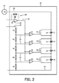
図2に図示されているように、LED照明10のトランジスタT1、T2、T3、T4は、対応するLED領域14をオフに切り換えるため、その対応するLED領域14をブリッジし得る。対応するLED領域14を迂回する短絡は、対応するトランジスタT1、T2、T3、T4により供給され得る。その対応するLED領域14をオンに切り換えるためには、電流線18の電流が、対応するLED L1、L2、L3、L4を流れざるを得ないように、対応するLED領域の入力部と対応するLED領域の出力部との間の接続が、対応するトランジスタT1、T2、T3、T4によって切られ得る。例えば、0Vと12Vとの間の信号電圧に依存して、LED領域14の以下のスイッチング状態が供給され得る。
図2において図示されている実施例においては、例えば自動車のハンドルのハンドル角度に対応する信号電圧が、PWM信号として印加され、積分器30を有する変換回路28によってランプ信号に変換される。他の例においては、図示されている変換回路28は、省かれてもよく、且つ/又は図1に図示されているLED照明10の回路基板12に設けられてもよい。
In the embodiment shown in FIG. 2, for example, a signal voltage corresponding to the handle angle of the steering wheel of an automobile is applied as a PWM signal and converted into a ramp signal by a
図3において図示されているように、図1又は図2において図示されているようなLED照明10を有する曲げ照明32が供給され得る。LED照明10は、ハウジング34を有し、ハウジング34には、駆動電子部品を備える回路基板12が組み込まれる。ハウジング34は、好ましくは、ハウジング34の2つの部分の間に回路基板12を固定するために2つの部分から成る。ハウジング34は、LED領域14を受けるための開口部36を有する。各開口部36及びその対応するLED領域14には、規定された明/暗カットオフを供給するためのコリメータ38が設けられる。曲げ照明32は、LED領域14によって放射された光を案内するための湾曲した半円柱形レンズ40を有する。曲げ照明32のLED領域14を1つずつオン又はオフに切り換えるため、ハンドルのハンドル角度に対応する信号電圧が、曲げ照明32のLED照明10に印加され得る。LED領域14を動作させるための電流源16は、LED照明10及び曲げ照明32から離れたところに配置され得る。例えば、LED照明10及び/又は曲げ照明32は、自動車の車体の外側に配置されてもよく、電流源16は、自動車のエンジン区画内に配置されてもよい。
As illustrated in FIG. 3, bending
本発明を、図面において図示し、上記の説明において詳細に説明しているが、このような図及び説明は、説明的なもの又は例示的なものとみなされるべきであって、限定するものとみなされるべきではない。本発明は、開示されている実施例に限定されない。例えば、信号線22の信号電圧が逆にされ、且つ/又は比較器C1、C2、C3、C4の+入力部と−入力部とが交換される実施例において本発明を動作させることが可能である。請求項に記載の発明を実施する当業者は、図面、明細及び添付の請求項の研究から、開示されている実施例に対する他の変形を、理解し、達成し得る。請求項において、「有する」という用語は、他の要素又はステップを除外せず、単数形表記は、複数の存在を除外しない。請求項において列挙されている幾つかのアイテムの機能を単一のプロセッサ又は他のユニットが実現してもよい。特定の手段が、相互に異なる従属請求項において引用されているという単なる事実は、これらの手段の組み合わせが有利になるように使用されることができないと示すものではない。請求項におけるいかなる参照符号も、範囲を限定するものとして解釈されてはならない。
While the invention is illustrated in the drawings and has been described in detail in the foregoing description, such illustration and description are to be considered illustrative and exemplary and limited Should not be considered. The invention is not limited to the disclosed embodiments. For example, it is possible to operate the invention in an embodiment in which the signal voltage on the
Claims (9)
各LED領域が少なくとも1つのLEDを有する幾つかのLED領域と、
前記LED領域を支持するためのハウジングと、
前記LED領域を動作させるための駆動電子回路を有し、且つ前記ハウジングに組み込まれた回路基板と、を有するLED照明であって、
前記LED領域が、自動車のステアリング方向と一致するよう配置され、且つ前記駆動電子回路によって直列に接続され、
前記駆動電子回路が、前記LED領域に電流を印加するための電流源に接続されるよう適応され、
前記駆動電子回路が、自動車のステアリング状態に対応する信号に接続されるよう適合され、
前記信号は前記電流源とは独立であり、
前記駆動電子回路は、前記信号に依存して1つ以上のLED領域をオン及びオフに切り換えるよう適応され、
割り当てられるLED領域を完全に又は部分的にオン及びオフに切り換えるためのトランジスタが、各LED領域に割り当てられ、
各トランジスタが、比較器を介して前記信号に接続され、各比較器が、前記信号を、異なるしきい値と比較するよう適合され、前記しきい値が、前記直列における特定の前記LED領域の位置に対応する、
LED照明。 LED lighting for automobiles,
Several LED regions, each LED region having at least one LED;
A housing for supporting the LED region;
A LED board having drive electronics for operating the LED region and having a circuit board built into the housing,
The LED regions are arranged to coincide with the steering direction of the vehicle and are connected in series by the drive electronics;
The drive electronics is adapted to be connected to a current source for applying a current to the LED region;
The drive electronics is adapted to be connected to a signal corresponding to the steering state of the vehicle;
The signal is independent of the current source;
The drive electronics is adapted to switch one or more LED regions on and off depending on the signal;
A transistor for switching the assigned LED area completely or partially on and off is assigned to each LED area,
Each transistor is connected to the signal via a comparator, and each comparator is adapted to compare the signal to a different threshold value, the threshold value of the particular LED region in the series. Corresponding to the position,
LED lighting.
Applications Claiming Priority (3)
| Application Number | Priority Date | Filing Date | Title |
|---|---|---|---|
| EP08166998.8 | 2008-10-20 | ||
| EP08166998 | 2008-10-20 | ||
| PCT/IB2009/054488 WO2010046806A1 (en) | 2008-10-20 | 2009-10-13 | Led light |
Publications (3)
| Publication Number | Publication Date |
|---|---|
| JP2012506121A JP2012506121A (en) | 2012-03-08 |
| JP2012506121A5 JP2012506121A5 (en) | 2014-02-20 |
| JP5934508B2 true JP5934508B2 (en) | 2016-06-15 |
Family
ID=41507829
Family Applications (1)
| Application Number | Title | Priority Date | Filing Date |
|---|---|---|---|
| JP2011531615A Active JP5934508B2 (en) | 2008-10-20 | 2009-10-13 | LED lighting |
Country Status (5)
| Country | Link |
|---|---|
| US (1) | US9481293B2 (en) |
| EP (1) | EP2340186B1 (en) |
| JP (1) | JP5934508B2 (en) |
| CN (2) | CN105539271B (en) |
| WO (1) | WO2010046806A1 (en) |
Families Citing this family (30)
| Publication number | Priority date | Publication date | Assignee | Title |
|---|---|---|---|---|
| JP5636756B2 (en) * | 2010-06-17 | 2014-12-10 | スタンレー電気株式会社 | Vehicle lamp unit |
| US8476837B2 (en) * | 2010-07-02 | 2013-07-02 | 3M Innovative Properties Company | Transistor ladder network for driving a light emitting diode series string |
| DE102011112716A1 (en) | 2011-09-07 | 2013-03-07 | Audi Ag | Method for operating a headlamp of a motor vehicle |
| FR2979970B1 (en) * | 2011-09-13 | 2019-11-29 | Valeo Vision | LIGHTING AND / OR SIGNALING DEVICE FOR MOTOR VEHICLE |
| DE102012000605B4 (en) * | 2011-10-27 | 2016-01-07 | Diehl Aerospace Gmbh | Lighting device for an AC power supply |
| CN102497695A (en) * | 2011-11-18 | 2012-06-13 | 上海晶丰明源半导体有限公司 | LED linear constant current control circuit and LED linear circuit |
| AT512603B1 (en) | 2012-02-24 | 2014-06-15 | Zizala Lichtsysteme Gmbh | LED control for running light indicators |
| AT512545B1 (en) * | 2012-02-16 | 2017-05-15 | Zkw Group Gmbh | Status display for the state of an operationally relevant component of a motor vehicle |
| AT512544B1 (en) | 2012-02-16 | 2014-02-15 | Zizala Lichtsysteme Gmbh | METHOD FOR GENERATING A CONTINUOUS EFFECT ON A LIGHTING STRUCTURE AND LIGHTING STRUCTURE |
| CN102665324A (en) * | 2012-04-12 | 2012-09-12 | 上海晶丰明源半导体有限公司 | LED linear driving circuit applicable to thyristor dimmer and control method |
| US10359452B2 (en) * | 2012-07-11 | 2019-07-23 | Hewlett-Packard Development Company, L.P. | Diagnostic device, apparatus and method |
| CN104755355B (en) | 2012-10-23 | 2018-01-26 | Tk控股公司 | Steering wheel lamp bar |
| CN104736412B (en) | 2012-10-23 | 2018-06-29 | Tk控股公司 | Steering wheel lamp bar |
| CN110877568B (en) | 2012-10-23 | 2023-05-05 | Tk控股公司 | Steering wheel light bar |
| KR102007403B1 (en) * | 2012-11-02 | 2019-08-05 | 엘지이노텍 주식회사 | Light emitting device package and lighting unit including the same |
| DE102013102203A1 (en) * | 2013-03-06 | 2014-09-11 | Hella Kgaa Hueck & Co. | Lighting device for a motor vehicle |
| FR3020547A1 (en) * | 2014-02-20 | 2015-10-30 | Valeo Vision | ELECTRICAL POWER SUPPLY FOR LIGHT EMITTING DIODE NETWORK |
| FR3022328B1 (en) * | 2014-06-16 | 2016-06-10 | Valeo Vision | ROTARY LIGHTING AND / OR SIGNALING MODULE |
| JP6648109B2 (en) | 2014-07-23 | 2020-02-14 | ジョイソン セイフティ システムズ アクイジション エルエルシー | Steering grip light bar system |
| JP6770892B2 (en) | 2014-12-25 | 2020-10-21 | 株式会社小糸製作所 | Lighting circuit and vehicle lighting |
| US9533687B2 (en) | 2014-12-30 | 2017-01-03 | Tk Holdings Inc. | Occupant monitoring systems and methods |
| US10614328B2 (en) | 2014-12-30 | 2020-04-07 | Joyson Safety Acquisition LLC | Occupant monitoring systems and methods |
| US10532659B2 (en) | 2014-12-30 | 2020-01-14 | Joyson Safety Systems Acquisition Llc | Occupant monitoring systems and methods |
| US9580012B2 (en) | 2015-03-02 | 2017-02-28 | Tk Holdings Inc. | Vehicle object detection and notification system |
| USD806729S1 (en) | 2015-04-24 | 2018-01-02 | Tk Holdings, Inc. | Display screen with graphical user interface |
| WO2016172709A1 (en) | 2015-04-24 | 2016-10-27 | Tk Holdings Inc. | Steering wheel light bar |
| WO2018129189A1 (en) | 2017-01-04 | 2018-07-12 | Joyson Safety Systems Acquisition Llc | Vehicle illumination systems and methods |
| US10953791B2 (en) | 2018-03-08 | 2021-03-23 | Joyson Safety Systems Acquisition Llc | Vehicle illumination systems and methods |
| TWI674036B (en) | 2018-12-13 | 2019-10-01 | 群光電能科技股份有限公司 | Lighting system |
| CN115734416B (en) * | 2022-10-18 | 2023-09-19 | 深圳市美矽微半导体有限公司 | LED wide voltage self-adaptive control method, control circuit and display device |
Family Cites Families (25)
| Publication number | Priority date | Publication date | Assignee | Title |
|---|---|---|---|---|
| US3796951A (en) * | 1971-06-28 | 1974-03-12 | Fmc Corp | Solid state electronic gauge |
| JPS57167492U (en) * | 1981-04-16 | 1982-10-21 | ||
| JPS61234496A (en) | 1985-04-10 | 1986-10-18 | 松下電器産業株式会社 | Automatic dimmer display |
| KR910007453B1 (en) * | 1987-12-10 | 1991-09-26 | 가부시기가이샤 고이또 세이사꾸쇼 | Illuminating angle adjusting device for vehicle head lamp |
| JPH02283539A (en) | 1989-04-21 | 1990-11-21 | Mitsubishi Cable Ind Ltd | Signal pattern display device for automobile |
| JPH0830917B2 (en) | 1990-04-18 | 1996-03-27 | シャープ株式会社 | Copying device |
| US5101326A (en) * | 1990-09-27 | 1992-03-31 | The Grote Manufacturing Co. | Lamp assembly for motor vehicle |
| US5765940A (en) * | 1995-10-31 | 1998-06-16 | Dialight Corporation | LED-illuminated stop/tail lamp assembly |
| EP0967590A1 (en) | 1998-06-25 | 1999-12-29 | Hewlett-Packard Company | Optical display device using LEDs and its operating method |
| TW493054B (en) * | 1999-06-25 | 2002-07-01 | Koninkl Philips Electronics Nv | Vehicle headlamp and a vehicle |
| JP2001213227A (en) | 2000-02-04 | 2001-08-07 | Koito Mfg Co Ltd | Lighting system for vehicle |
| DE10159765C2 (en) * | 2001-12-05 | 2003-11-06 | Audi Ag | Arrangement for controlling a number of light-emitting diodes and method for operating such an arrangement |
| JP2004136719A (en) * | 2002-10-15 | 2004-05-13 | Koito Mfg Co Ltd | Lighting circuit |
| DE10260796B3 (en) * | 2002-12-23 | 2004-09-02 | Daimlerchrysler Ag | Control device for vehicle signal lights, has clock circuit that individually controls load current of at least two signal lights with defined clock sequence and is supplied by signal transmitter circuit |
| FR2857921B1 (en) * | 2003-07-24 | 2006-11-24 | Valeo Vision | FIXED LIGHT PROJECTOR OF TURN FOR MOTOR VEHICLE |
| DE102004055882A1 (en) | 2004-11-19 | 2006-06-01 | Audi Ag | Headlight of vehicle, comprising arrangement for variable illumination of bend in relation to data received from steering angle sensor |
| JP5188690B2 (en) | 2006-08-29 | 2013-04-24 | アバゴ・テクノロジーズ・イーシービーユー・アイピー(シンガポール)プライベート・リミテッド | Apparatus and method for driving an LED |
| JP2008074327A (en) | 2006-09-25 | 2008-04-03 | Mazda Motor Corp | Vehicular lighting system |
| FR2906672A1 (en) | 2006-09-28 | 2008-04-04 | Valeo Vision Sa | DEVICE FOR MONITORING A PLURALITY OF LOADS LIKE LIGHT SOURCES AND DEVICE FOR LIGHTING AND / OR SIGNALING A VEHICLE INCORPORATING SUCH A CONTROL DEVICE |
| WO2008038984A1 (en) * | 2006-09-29 | 2008-04-03 | Seoul Semiconductor Co., Ltd. | Light emitting diode assembly |
| AT504949B1 (en) * | 2007-02-20 | 2008-11-15 | Zizala Lichtsysteme Gmbh | CIRCUIT ARRANGEMENT FOR DETECTING A SHORT-CIRCUIT OF LUMINOUS DIODES |
| CN101378613B (en) * | 2007-08-27 | 2012-07-04 | 佶益投资股份有限公司 | LED light source and LED lamp body |
| JP2009134933A (en) * | 2007-11-29 | 2009-06-18 | Mitsubishi Electric Corp | Led lighting device, and headlight for vehicle |
| JP2009205846A (en) * | 2008-02-26 | 2009-09-10 | Koito Mfg Co Ltd | Vehicular lighting control device |
| CN102667326B (en) * | 2009-06-03 | 2016-08-10 | 沃克斯材料有限公司 | Lamp assembly and manufacture method |
-
2009
- 2009-10-13 EP EP09743918.6A patent/EP2340186B1/en active Active
- 2009-10-13 CN CN201510983470.9A patent/CN105539271B/en active Active
- 2009-10-13 US US13/124,911 patent/US9481293B2/en active Active
- 2009-10-13 WO PCT/IB2009/054488 patent/WO2010046806A1/en active Application Filing
- 2009-10-13 JP JP2011531615A patent/JP5934508B2/en active Active
- 2009-10-13 CN CN2009801415856A patent/CN102186697A/en active Pending
Also Published As
| Publication number | Publication date |
|---|---|
| EP2340186B1 (en) | 2018-12-19 |
| US20110198999A1 (en) | 2011-08-18 |
| CN102186697A (en) | 2011-09-14 |
| US9481293B2 (en) | 2016-11-01 |
| WO2010046806A1 (en) | 2010-04-29 |
| CN105539271A (en) | 2016-05-04 |
| CN105539271B (en) | 2018-02-13 |
| JP2012506121A (en) | 2012-03-08 |
| EP2340186A1 (en) | 2011-07-06 |
Similar Documents
| Publication | Publication Date | Title |
|---|---|---|
| JP5934508B2 (en) | LED lighting | |
| ES2688940T3 (en) | LED fault detection circuit | |
| JP2010522113A (en) | Lighting device | |
| JP2012506121A5 (en) | ||
| US20050265039A1 (en) | Two circuit led light bulb | |
| CN104214629B (en) | Lighting device for vehicle | |
| US9187026B2 (en) | Lighting control system for vehicle lamp | |
| US8598735B2 (en) | Control unit for controlling an illumination device for a motor vehicle as well as an illumination device for a motor vehicle with such a control unit | |
| KR102564287B1 (en) | Lighting device carrying out multiple lighting functions of an automotive vehicle using functionally dedicated light source groups | |
| US7345433B2 (en) | Reversible polarity LED lamp module using current regulator and method therefor | |
| CN107426852A (en) | Lamp device and the Vehicular illumination system with lamp device | |
| JP2009509306A (en) | Automotive lighting system | |
| CN103650640A (en) | Circuit arrangement, lighting unit for a vehicle and method for driving semiconductor lighting elements | |
| CN105371203A (en) | Motorcycle LED light system | |
| KR102323293B1 (en) | Automotive led lighting module | |
| KR20100084695A (en) | Led onboard power system | |
| JP2011073509A (en) | On-vehicle lamp lighting control circuit | |
| JP4101559B2 (en) | Lighting device lighting circuit | |
| KR101847801B1 (en) | Circuit for outputting reference voltage of led driving module for a vehicle lamp | |
| KR200388132Y1 (en) | Apparatus for displaying bus line number | |
| JP2016012471A (en) | Led lamp unit and lamp device for vehicle | |
| JP2005029019A (en) | Constant current driving circuit of electronic light emitting element and electronic light emitting element driving circuit of lighting fixture for vehicle | |
| JP2022049515A (en) | Lamp control module, vehicular lamp, and signal processing device | |
| JP2011073507A (en) | Onboard lamp lighting control device | |
| CN110382294A (en) | Vehicle electrical systems |
Legal Events
| Date | Code | Title | Description |
|---|---|---|---|
| A621 | Written request for application examination |
Free format text: JAPANESE INTERMEDIATE CODE: A621 Effective date: 20121003 |
|
| A131 | Notification of reasons for refusal |
Free format text: JAPANESE INTERMEDIATE CODE: A131 Effective date: 20131031 |
|
| A524 | Written submission of copy of amendment under article 19 pct |
Free format text: JAPANESE INTERMEDIATE CODE: A524 Effective date: 20131227 |
|
| A02 | Decision of refusal |
Free format text: JAPANESE INTERMEDIATE CODE: A02 Effective date: 20140529 |
|
| A521 | Request for written amendment filed |
Free format text: JAPANESE INTERMEDIATE CODE: A523 Effective date: 20140926 |
|
| A911 | Transfer to examiner for re-examination before appeal (zenchi) |
Free format text: JAPANESE INTERMEDIATE CODE: A911 Effective date: 20141006 |
|
| A912 | Re-examination (zenchi) completed and case transferred to appeal board |
Free format text: JAPANESE INTERMEDIATE CODE: A912 Effective date: 20141205 |
|
| RD03 | Notification of appointment of power of attorney |
Free format text: JAPANESE INTERMEDIATE CODE: A7423 Effective date: 20150608 |
|
| A521 | Request for written amendment filed |
Free format text: JAPANESE INTERMEDIATE CODE: A523 Effective date: 20151109 |
|
| A521 | Request for written amendment filed |
Free format text: JAPANESE INTERMEDIATE CODE: A523 Effective date: 20160224 |
|
| A61 | First payment of annual fees (during grant procedure) |
Free format text: JAPANESE INTERMEDIATE CODE: A61 Effective date: 20160509 |
|
| R150 | Certificate of patent or registration of utility model |
Ref document number: 5934508 Country of ref document: JP Free format text: JAPANESE INTERMEDIATE CODE: R150 |
|
| S111 | Request for change of ownership or part of ownership |
Free format text: JAPANESE INTERMEDIATE CODE: R313113 |
|
| R350 | Written notification of registration of transfer |
Free format text: JAPANESE INTERMEDIATE CODE: R350 |
|
| R250 | Receipt of annual fees |
Free format text: JAPANESE INTERMEDIATE CODE: R250 |
|
| R250 | Receipt of annual fees |
Free format text: JAPANESE INTERMEDIATE CODE: R250 |
|
| R250 | Receipt of annual fees |
Free format text: JAPANESE INTERMEDIATE CODE: R250 |
|
| R250 | Receipt of annual fees |
Free format text: JAPANESE INTERMEDIATE CODE: R250 |
|
| R250 | Receipt of annual fees |
Free format text: JAPANESE INTERMEDIATE CODE: R250 |